YONGNUO PHOTOGRAPHIC EQUIPMENT RF603C Wireless Flash Trigger User Manual RF603 II Usermanual 20140620

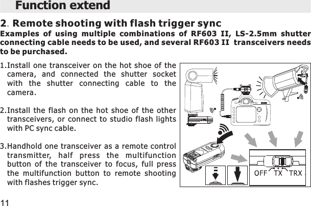
SHENZHEN YONGNUO PHOTOGRAPHIC EQUIPMENT CO., LTD Wireless Flash Trigger RF603 II Usermanual 20140620

Users Manual

Wireless Flash Trigger 无线引闪器User Manual使用手册
Thank you for purchasing YongNuo products in advance.Please  read  this  user  manual  carefully  and  learn  how  to  use  camera  and flash before.This product is a wireless transceiver integrated design, for the convenience of  description, the product will named “transmitter” when mounted on the camera  hot  shoe  in  some  cases,  while  named  “receiver”  when  mounted  or connected to the flash. ContentsGeneral description . . . . . . . . . . . . . . . . . . . . . . . . . . . . . . . . . . . . . . . . . . 1           Cautions . . . . . . . . . . . . . . . . . . . . . . . . . . . . . . . . . . . . . . . . . . . . . . . . . . . 2The name of each part for RF603 II . . . . . . . . . . . . . . . . . . . . . . . . . . . . . . 4                    Preparation before using . . . . . . . . . . . . . . . . . . . . . . . . . . . . . . . . . . . . 5-7        Wireless flash trigger awaken & testing . . . . . . . . . . . . . . . . . . . . . . . . . . 8         Wired/wireless remote shutter release . . . . . . . . . . . . . . . . . . . . . . . . . . . 9        Function extend . . . . . . . . . . . . . . . . . . . . . . . . . . . . . . . . . . . . . . . . . 10-11     Troubleshooting. . . . . . . . . . . . . . . . . . . . . . . . . . . . . . . . . . . . . . . . . . . . 12Specification . . . . . . . . . . . . . . . . . . . . . . . . . . . . . . . . . . . . . . . . . . . . . . 13  Include items/Optional Accessories  . . . . . . . . . . . . . . . . . . . . . . . . . . . . 3
General descriptionRF603 II adopts a global free FSK 2.4GHz wireless channel which can be suitable in  many  countries.  RF603  II  with  FSK  system,  can  be  more  effective  to  guarantee speed,  distance  and  stability.  Within  capacious  areas,  the  remote  control  distance may reach to 100m, and suitable for RF603I.RF603 II wireless  flash  trigger  kit is formed  by two same transceivers. It  can be set to single transmit state (TX), which will be more convenient for testing flash, and can be set to transceiver state (TRX), automatically switch transmit and receive state, adopts focus and shutter function in “TX” and “TRX” state respectively. Transmitter supports single contact triggering, supports wireless wakening up  and  triggering  the  flash  through  the  camera  hot  shoe,  with  PC  sync  cable (optional) can be trigger studio lights, with specially camera shutter connecting cable can  realize  wired  /  wireless  shutter  release  remote  control,  supports  controlling multiple cameras and flashes at the same time. The highest flash sync speed up to 1/320 second (some of models may only reach to  1/250s  or  less, difference  combination  of  models of  flash  and  camera  using may achieved difference flash sync speed).2  levers  button  design  ,  it  will  realize  the  awakening,  flash  testing, 1
Cautions1. As  this is an electronic  product accessory, some  of the environment  causes may  affect  the  working.  However  this  is  hardly  ever  to  get  this  situation, don't worry.2. Do not pull the wires and turn off the camera when connecting.3. For  a  long  time  non-use,  please  turn  the  transceiver  off  and  remove  the batteries.4. Do not put it in high temperature, such as a closed car under direct sunlight, the control panel and other high temperature areas.5. Keep dry, do  not  use wet hands contact  with the product, the product must not be immersed in water or exposed to rain, and this may and this may lead to not work properly.6. Do not used in the flammable occasion in violation of this warning may cause an explosion or fire.7. Owing to this product include battery, please operate it strictly according to related rules, otherwise maybe cause explosion, fire or physical injury.8. Do not trigger the flash close to a person's eyes, it may impair the person's vision.2
2.The LS-2.5 series shutterconnecting cable1.The LS-PC series flash cableC1Canon60D/350D/450D/500D/550D/600D/650D/700D Pentax SeriesC3Canon1D/5D/7D/10D/20D/30D/40D/50DN1NikonD1/D2/D3/D4 SeriesD200/D300D700/D800N2 NikonD70/D70S/D80N3NikonD90/D600D3000/D5000 SeriesD7000 SeriesInclude items/Optional Accessories 3Include items:RF603C II or RF603N II . . X2LS-2.5 Shutter Cable* . . X1User Manual .......X1*Shutter Cable  shown according to the packaging.Optional Accessories: LS-PC635   LS-PC/PCYou  can  additionally  purchase  the  shutter cable or PC sync cable if needed. LS-2.5/C1...
The name of each parts of RF-603 IIThe  RF603C  II  is more suitable for Canon cameras.The  RF603N  II  is more suitable for Nikon cameras.4A: Focusing indicator light (green) / Shutter indicator light (red)B: 2.5mm shutter remote cable socket C: Hot shoe / Hot shoe contacts  D: PC socket(output) E: Awakening indicator light (green) /Flash trigger indicator light (red)     F: Multifunction button G: Power switch-1.TX  2.TRX(transmit-receive )     H: Locking ring    I: Hot shoe mounting foot          J: Contacts     K: Channel setting switch   L: Battery room M:Battery door  (transmit)
Preparation before using1.Channel Setting:Use the  channel  setting  switch  to set  the  transceivers to the same code, total 32 channels.2.Battery Installation:Slide  to  open  the  battery  room,  install  two  AAA batteries(not include) for two transceiver according to the "+/-" marks shown.3.Fix the transceiver on the camera hot shoe:Mount the transceiver on the hot shoe of the camera by hot shoe mounting foot, then tight the locking screw.Support installing the flash on the transceiver (The On-Top Flash,as the picture shown). 5
Preparation before using4.Fix the transceiver on light stand or flash bracket :Mount  the  transceiver  on  the  mini  stand  of  the  flash attached or other fixed device (not included), and tight the locking screw.5.Fix the flash on transceiver:Install the flash on the hot shoe of the transceiver, lock the flash and ensure all links are fixed well.6.Use the PC port to connect other type of flashes :To  realize  the  function  you need  to  additionally  purchase the LS-PC series cable according to the different interface.1.Inset the PC cable with the end of nutsert to PC socket ofthe transceiver, and tight the nutsert.2.Inset another end of the cable to the synchronous socketof the the flash.The PC port just used as output to connect the flash. 6
Preparation before using7.Po wer  S witch  and  Tra nsmit-recei ve  Stat eSettings:Set  the  power  switch  on  TX  (single  transmit)  or  TRX (transmit-receive  automatic  switch)  state  according  to different  shooting  requirement.  When  it  used  as  wireless triggering  transmitter  and  flash  testing,  set  to  "TX";  while used as wireless triggering receiver, using shutter  release or other  extended  functions,  set  to  "TRX",  as  the  table  shown, set to OFF means turn off the power. 7FMake sure all  the  transceivers have been  fixed  before using , the  flash need to set to manual “M” mode.
1.The flash AwakeningHalf  press the multifunction  button of the transmitter or the button  of  camera shutter, the awakening indicator light of transmitter and receiver will be bright (Green), at the moment if the flash is in dormant state, it will be awakened. 2.Test and trigger the flashFully press the multifunction button of transmitter to test the flash once. When fully pressing the release button of camera shutter, it will synchronously trigger the  on-top  flash  and  off-camera  flash,  the  flash  trigger  indicator  light  of transmitter and receiver will be bright (Red).FIt requires compatible transmitter when using the camera shutter to awake the  flash,  non  specialized  transmitter  can  also  wireless  trigger  the  flash normally (single contact trigger). Wireless flash trigger & testing8
Wired/wireless remote shutter release function This  product  can  achieve  wired  /wireless  remote shutter release function, need to LS-2.5 series shutter connecting  ca ble(or  purchase)  accordi ng  to  the different cameras. When using the shutter release, the power switch need to set in”TRX” state. 1.As the picture shown, use  the shutter  release between the shutter socket of camera and transceiver. 2.Single transceiver can be used as wired shutter release. 3.When using as a wireless shutter release, fix  a transceiver on the camera hot shoe or fix around the camera with the external  socket  of  camera  shutter  through  specialized shutter cable to connect, another transceiver set on hand. 4.Half  press  the  multifunction  button  of  transmitter,  the camera  will  enter  into  focusing.  The  Focusing  indicator light  will  bright,  fully  press  the  button,  the  camera  will enter  into  shooting,  at  the  moment,  the  red  shutter indicator light bright. 9
Function extend 1.Handhold the flash for remote flash trigger syncTake the RF603 II on the flash as shutter release remote control, LS-2.5mm series  shutter  connecting  cable  needs  to  be  used.  The  transceivers  should set in “TRX” state. 101.Install the handhold flash on the hot shoeof the transceiver as transmitter, and lockthe flash.2.Fixed  the  camera  (such  as  on  a  tripod),installed  the  other  transceiver  on  the  hotshoe  of  the  camera  as  receiver,andconnected  with  specialized  shutter  cableto  the  external  shutter  socket  of  thecamera.3.Press  the  multifunction  button  of  thetransceiver  on  flash  for  remote  shooting,and  the  flash  will  be  trigger  with  shuttersynchronously.
2.Remote shooting with flash trigger syncExamples  of  using  multiple  combinations  of  RF603  II,  LS-2.5mm  shutter connecting cable needs to be used, and several RF603 II  transceivers needs to be purchased.Function extend 111.Install  one  transceiver  on  the  hot  shoe  of  thecamera,  and  connected  the  shutter  socketwith  the  shutter  connecting  cable  to  thecamera.2.Install  the  flash  on  the  hot  shoe  of  the  othertransceivers,  or  connect  to  studio  flash  lightswith PC sync cable.3.Handhold  one transceiver as a remote  controltransmitter,  half  press  the  multifunctionbutton  of  the  transceiver  to  focus,  full  pressthe  multifunction  button  to  remote  shootingwith flashes trigger sync.
Troubleshooting 1.Unable  or wireless trigger the flash FFSet the power  switch of transmitter  to TX state  then test the  flash, it could not test flash when setting to TRX state. FMake sure the flash have been prepared and set to manual “M” mode. FThe poor contact between transmitter, camera and flash will cause the triggering problem,  ensure  the  contacts  are  clean  and  have  been  installed  to  the  correct position.  2.Unable to awake the flashFWhen  using  the  non  specialized  transmitter, it need to half press the button of transmitter to awake the flash when the transmitter set in TX state. If the flash could not be awaken, it need to  manual awake the flash or turn off the power saving mode.3.The shutter could not be releasedFWhen part of the cameras could not find the focus, it could not proceed to shoot even if receiving the shooting signal. The focus mode of camera should be adjusted to “M”. to test the flash Make sure the battery is full and  the transceivers are in the same channel. 12
Type: FSK 2.4GHz wireless remote control systemTransmission distance: 100mChannels: 32 channelsShutter release: half-press, full-pressShutter interface: 2.5mm socketStudio flash light interface: standard PC socketMax Sync Speed: 1/320 secondBattery: AAA×2(3V )Stand-by time:about 400 hours in TX state,about 45 hours in TRX mode. Size (W x H x D): 38MM x 88MM x 33.5MMThe functions of this user manual are based on test conditions of our company.Further notice will not be given if the design and specifications change.The  YONGNUO  logo  in  this  manual  includes  the  registered trademark  or  trademark  of  Shenzhen  Yongnuo  Photography Equipment Co.,Ltd in China or/and other countries(regions).All other trademarks are the property of their respective owners.Specification13
 Changes or modifications not expressly approved by the party responsible for compliance could void the user's authority to operate the equipment。 Note: This equipment has been tested and found to comply with the limits for a Class B digital device, pursuant to part 15 of the FCC Rules. These limits are designed to provide reasonable protection against harmful interference in a residential installation. This equipment generates, uses and can radiate radio frequency energy and, if not installed and used in accordance with the instructions, may cause harmful interference to radio communications. However, there is no guarantee that interference will not occur in a particular installation. If this equipment does cause harmful interference to radio or television reception, which can be determined by turning the equipment off and on, the user is encouraged to try to correct the interference by one or more of the following measures:   —Reorient or relocate the receiving antenna.   —Increase the separation between the equipment and receiver.   —Connect the equipment into an outlet on a circuit different from that to which the receiver is connected.   —Consult the dealer or an experienced radio/TV technician for help. FCC ID: 2ACYPRF603C This device complies with Part 15 of the FCC Rules. Operation is subject to the following two conditions: (1) this device may not cause harmful interference, and (2) this device must accept any interference received, including interference that may cause undesired operation.

Navigation menu