YONGNUO PHOTOGRAPHIC EQUIPMENT YN622C E-TTL Wireless Flash Trigger Transceiver User Manual 622
SHENZHEN YONGNUO PHOTOGRAPHIC EQUIPMENT CO., LTD E-TTL Wireless Flash Trigger Transceiver 622
UserManual.wiki
>
YONGNUO PHOTOGRAPHIC EQUIPMENT
>
YN622C User Manual
User Manual
Navigation menu
Upload a User Manual
Namespaces
Wiki Guide
HTML
PDF
Info
Views
User Manual
Discussion / Help
Navigation
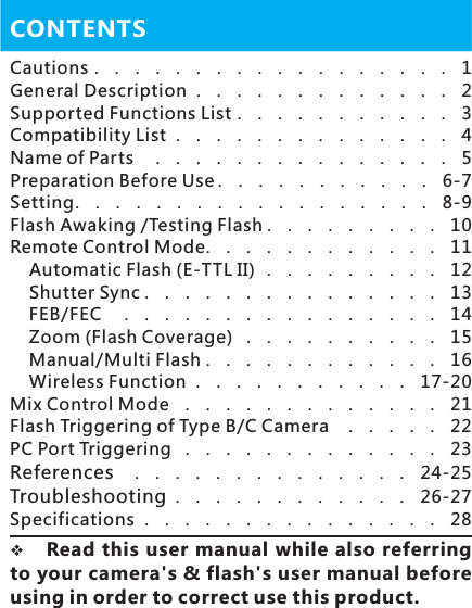
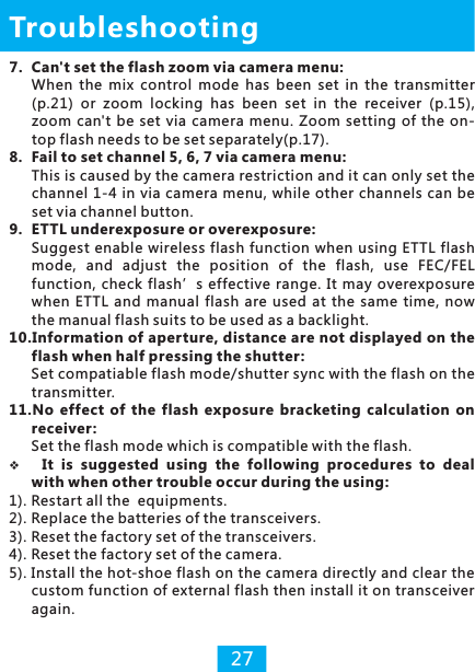
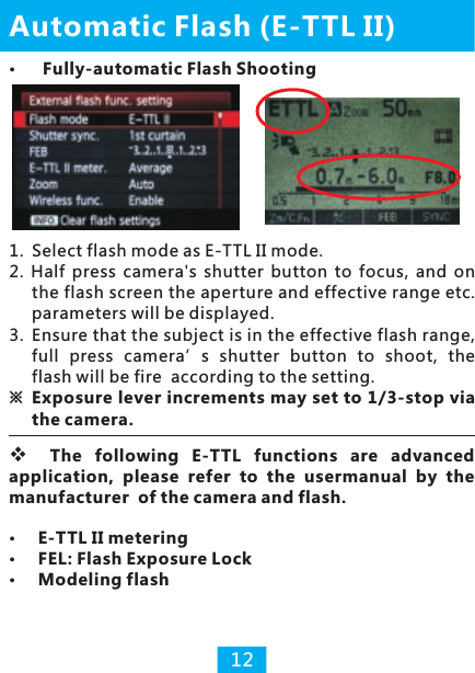
![1. Power SwitchPower on when the power switch slides to [ON], channel and group indicators shows that channel and receiving group, power off when the power switch slides to [OFF].※It is normal for the flash fire once when turning on/off the transceiver.2. Channel Setting (Press [CH SET] Button)Press [CH SET] button and the channel indicator will keep lighting for several seconds to indicate the current channel, at this time shortly press [CH SET] button again to change channel, and there are totally 7 channels. Set all the transceivers at same channel.SettingCh7Ch6Ch5Ch4Ch3Ch2Ch1Press [GP SET] button to check the cu rrent rece iv ing gro u p, th en shortly press [GP SET] button again to change among A/B/C three groups. Group indicator and state indic ator( red ) will blink whi le receive co mmunicating at the same time. 83. Receiving Group Setting (Press [GP SET] Button)](https://usermanual.wiki/YONGNUO-PHOTOGRAPHIC-EQUIPMENT/YN622C/User-Guide-2365352-Page-10.png)
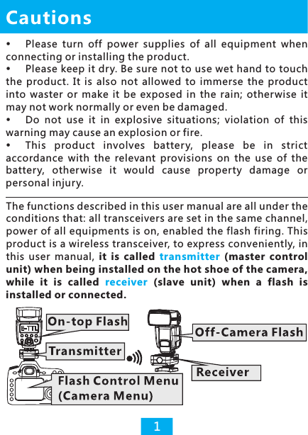
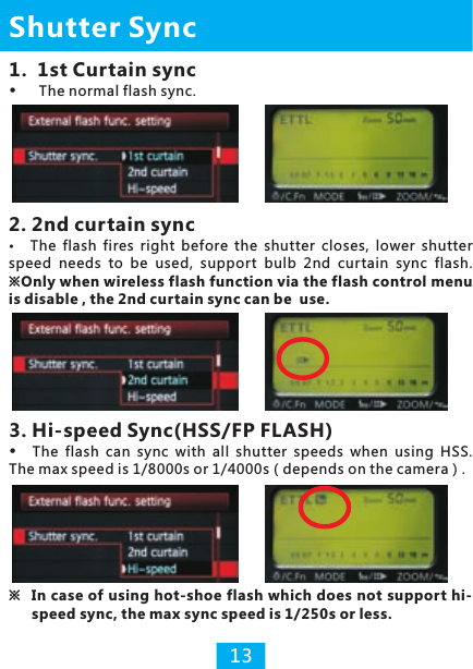
![4.Flash Test Group Setting (Test + GP SET Button)Set flash testing group Type C camera uses the set firing group.Setting91. H o l d d o w n [ Te s t ] b u t t o n t h e n t h e g r o u p indicators will keep lighting, the flash on the receiver group having been selected will be woken up(p.10).2. Hold down [Test] button and repeat to shortly press [GP SET] button, selected groups of receivers to testing flash, and there are totally 7 combinations. 3. When loosening [Test] button, the flash of the group having been selected will fire a test flash(p.10).※ Testing group is different from iring g r o u p s e t t i ng o f ty p e A c am e r a r e f e r t o page 18 while page 22 for type B.firing group, f](https://usermanual.wiki/YONGNUO-PHOTOGRAPHIC-EQUIPMENT/YN622C/User-Guide-2365352-Page-11.png)
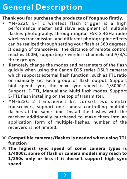
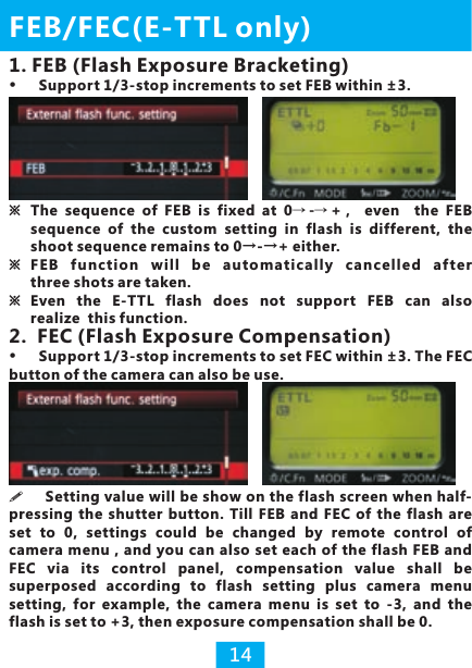
![When half-pressing the shutter button of the camera, the hot-shoe flash on the receiver will be awakened. (for A/B type camera only)Under any connection type, [Test] button can be pressed to awaken and test the flash on the transceiver and other transceivers at the same channel.Test flash with the mode set by the flash, and under the mode of E-TTL it may fire in a lower output.Refer to the following figure, the transmitter sets A +B two groups of flash test, hold down the[Test] button, the flash on A and B of the receiver will be awakened, and when loosening [Test] button will fire a test flash.Flash Awaking and Testing Flash※ If the flash can not be awakened, manually awaken the flash before shooting.※ Using PC port to connect with flash without the awakening function.※ All the indicators going out when flash fires.10](https://usermanual.wiki/YONGNUO-PHOTOGRAPHIC-EQUIPMENT/YN622C/User-Guide-2365352-Page-12.png)
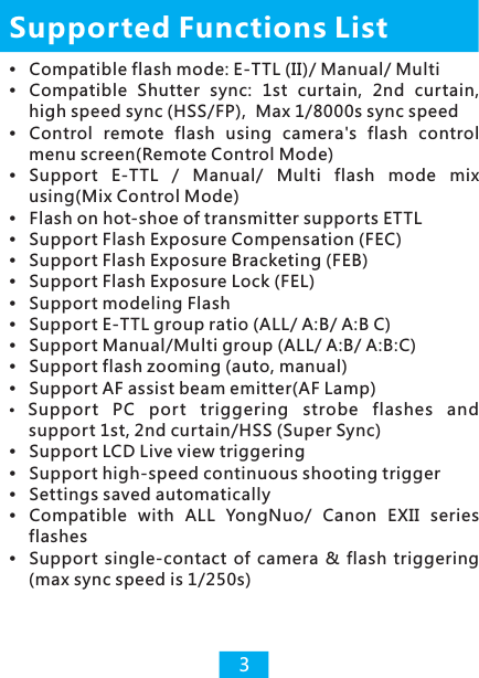
![1. Press down [MENU] button on the camera, select flash control-external flash function setting. When the off-camera setting which is consistent with the camera’s menu, the AF assist beam emitter of the receiver will blink twice to show that the change is successfully.(p. 24)2. Enabled the wireless flash function via the camera’s menu to realize firing group control.(p.17)3. Focus and shoot picture, the flash is fired according to the parameters set of all groups. Support the function of AF assist beam emitter of the transmitter. (p.24)Remote Control Mode11※Suggest disabled wireless flash function when using 2st curtain sync only.Remotely setting all the flashes through the external flash function setting (camera menu) of the camera, just likes the flash being directly installed on the camera. The settings of camera menu is prior, settings will upgraded to the receiver after pressing down camera confirmation button or half pressing shutter button without needing to operate the flash control panel, the flash’s screen will display the current setting. The setting varies depending on the cameras/flashes. This control mode is the default control mode, transmitter ’s channel indicator will goes out in standby state, the camera needs to be set at P/AV/TV/M exposure mode, and it for type A cameras only.](https://usermanual.wiki/YONGNUO-PHOTOGRAPHIC-EQUIPMENT/YN622C/User-Guide-2365352-Page-13.png)
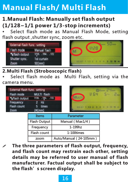
![Zoom supports automatic/manual setting.1. With automatic setting, focal length of the flash may change with lens focal length. 2. With manual setting, focal length of the flash supports manual setting within 24-105MM.1. Automatic Setting 2. Manual SettingZoom (Flash Coverage)3. Zoom Lock15Hold down the [CH SET] button of the receiver for seconds until channel indicator keeps lighting (same to set the mix control mode for the transmitter, p.21), enable the zoom lock function for the receiver, then the flash on the receiver will not be controlled by the camera menu, adjust flash zoom settings with flash control panel (automatic or manual), that means each flash can be set with a different focal. Hold down the [CH SET] for seconds again to cancel.](https://usermanual.wiki/YONGNUO-PHOTOGRAPHIC-EQUIPMENT/YN622C/User-Guide-2365352-Page-17.png)
![3.Channel Setting via Wireless Function ※When disabled the wireless function via the camera menu, in transmitting communications, group indicator will go out, firing group consists of all (A+B+C), all groups of flashes using the same setting.4. Firing Group Setting via Wireless FunctionSets firing group of the transmitter via wireless function setting, in transmitting communications, state indicator and group indicator both blinking green, the following table shows that each group indicator stands for different firing group available.Wireless FunctionSet channel (CH1-CH4 only) of the transmitter via wireless function setting, the changed shall cover the original setting. CH1-CH7 may also be set by directly pressing [CH SET] at the transmitter(p.8).18 Group Indicator Firing GroupIndicator A blinks ALL(A+B+C)Indicator B blinks (A:B)Indicator C blinks A:BC or A:B:CIndicator goes out ALL(A+B+C)](https://usermanual.wiki/YONGNUO-PHOTOGRAPHIC-EQUIPMENT/YN622C/User-Guide-2365352-Page-20.png)
![1. Hold down the [CH SET] button for several seconds of the transmitter until the channel indicator blinks for 3 times and then keep lighting, enable the mix control mode.2. Flash mode of the transmitter will be fixed at E-TTL and the zoom setting is disabled.3. Set the parameters of each flashes via it own control panel.Mix Control Mode21Set the flash on each receiver in different flash modes as Manual/E-TTL/Multi for mix control, the settings of the flash is prior , channel indicator of the transmitter will keep lighting when enabled this control mode. Supports type A/B cameras using. In the mix control mode, set items via the flash it supports: Flash mode (output), FEB, FEC, Zoom etc.Set the shutter sync via camera menu and the flash set is invalid (Type B camera defaults to hi-speed sync). ※ Disable the mix control mode by hold down [CH SET] button again then it will return to remote control mode (the channel indicator goes out in standby state).(p.11)](https://usermanual.wiki/YONGNUO-PHOTOGRAPHIC-EQUIPMENT/YN622C/User-Guide-2365352-Page-23.png)
![22Type B Cameras:There is no flash control menu of such type of cameras that some of function will be restricted. Enable the mix control mode of the transmitter before using(P.21).1.Setting of transmitting groups (set in the transmitter when it in transmitting status):Half press the camera’s shutter button then status indicator blinks green. Press [GP SET] to set transmitting firing groups.Flash Triggering of B/C Type CameraType C Cameras: Manually set the Flash Output1. Transmitting group set (via the transmitter):Set according to testing group of transmitter (p.9).2. Flash mode set (via the flash control panel):Set the manual(M) flash output via the control panel of the flash, and trigger with transmitter's main flash contact(single contact). Do not support hi-speed sync or other TTL functions.(Max speed sync is 1/250s or less)2.Setting of flash mode (via the flash control panel):1). Automatic (ETTL) mode supports automatic flash, supports the settings of FEC and FEB, it defaults to hi-speed sync.2). Manual (M) mode, manually set the flash output. It defaults to hi-speed sync.3). Multi mode, set according to the flash. Group Indicator Firing GroupIndicator A blinks ALL(A+B+C)Indicator B blinks (A:B)Indicator C blinks ALL(A+B+C)](https://usermanual.wiki/YONGNUO-PHOTOGRAPHIC-EQUIPMENT/YN622C/User-Guide-2365352-Page-24.png)
![ReferencesFactory Reset1) Hold down the buttons [CH SET] plus [GP SET] at the same time.2) The state indicators will blink for 3 times in red-green alternately then turn to keep lighting (red).3) Release all the buttons then reset the factory set.25About the Max Sync SpeedIt needs the camera and flash both support hi-speed sync, and the max sync speed is 1/8000s or 1/4000s. When using the hot shoe flash which doesn’t support hi-speed sync, the max sync speed is 1/250s or lower.About Automatic Saving FunctionThe transceiver will automatically save the sets such as channel, receiving group, AF assist beam. In the TTL set, some parameters will not be saved, such as the set of fire ratio etc.2 Transceiver Kit Packagedone off-camera flash or one off-camera flash plus one on-top flash can be used. Multiple TransceiversMultiple flashes application by ad di ti on al ly pu rc ha se d transceivers.Applications](https://usermanual.wiki/YONGNUO-PHOTOGRAPHIC-EQUIPMENT/YN622C/User-Guide-2365352-Page-27.png)
![Troubleshooting1. Fail to power on or automatic shutdown:● The battery is loaded inversely or exhausted; it will power off automatically when the battery is going to be exhausted in case of being over discharged.▲Install the battery according to the correct direction the battery compartment indicates and ensure the battery is full and restart the power (refer to page 8).2. The flash doesn't fire Ensure the power of all equipments are full, the connection among the transceiver, camera and the flash is reliable; whether the indicator is set in the same channels and controllable groups. Flashes recycle process, entering in the state of overheating protection, ongoing zoom adjustment, the flash enters into sleep status etc. may makes the flash doesn't fire . Ensure the flash is in ready state, use the [Test] button test the flash before using.3. Fail to enable the 2nd curtain sync:● That’s because the restriction of camera menu.▲It shall set the wireless function disabled if needs using the 2nd curtain sync.4. Can't access into the external flash function menu or the menu is displayed abnormally: ● The transmitter is not installed right , the contacts of the hot shoe is stained or the power of the battery is exhausted.▲Reinstall the transmitter and clean the contacts ,batteries.5. The assist beam emitter doesn't work:Refer to page 24.6. The on-top flash doesn't fire:Enabled the master flash via the wireless function setting.replace the 26](https://usermanual.wiki/YONGNUO-PHOTOGRAPHIC-EQUIPMENT/YN622C/User-Guide-2365352-Page-28.png)