Yaesu Musen 0A290910 Ultra-Low Power Wi-Fi Module User Manual OM
Yaesu Musen Co., Ltd. Ultra-Low Power Wi-Fi Module OM
Operating Manual Host
SSM-71H
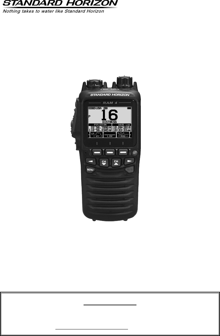
Wireless Remote Station Microphone RAM4W
The RAM4W (SSM-71H) allows you to remotely control all functions of the
enabled Standard Horizon xed mount VHF radio. The full dot matrix display
and programmable keys make operation simple and fast. Additional features
include turning the radio on/off and all DSC functions including Distress. The
four RAM4W (SSM-71H) can be connected to xed mount VHF radio with the
optional SCU-30 RAM4W Wireless Access Point. The RAM4W (SSM-71H) is
backed by an industry leading 3-years waterproof warranty.
Owner’s Manual
The details of the installation and operation of the RAM4W (SSM-71H) is
included in the owner’s manual of the compatible xed mount radio, or it can
be downloaded at www.standardhorizon.com.
Application for FCC / IC
FCC ID: K660A290X10 / IC: 511B-0A290X10
2SSM-71H Instruction Manual
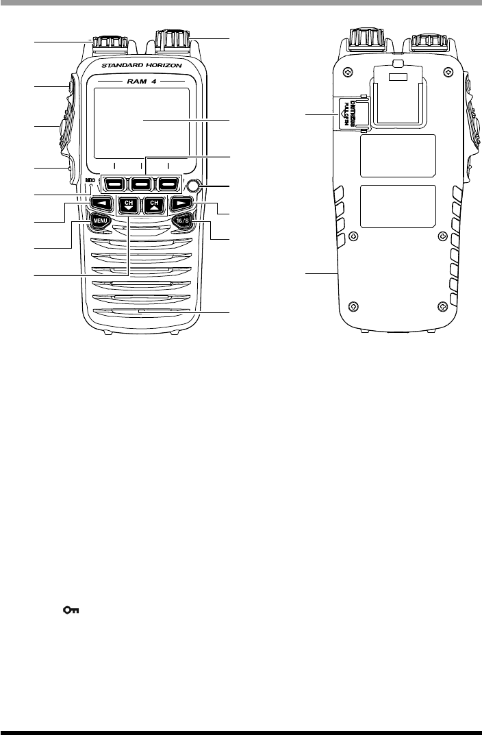
Front and Rear Panel
②①
③
④
⑤
⑥
⑦
⑧
⑨
⑩
⑪
⑫
⑦
⑬
⑭
⑮
⑯
① Power/VOL knob
Press and hold this knob to turn the transceiver and the remote mic on or off.
Turns the adjusts the speaker volume.
② DIAL/ENT knob
While the normal screen is displayed, rotate the DIAL/ENT knob to select your desired
channel. While the MENU screen is displayed, rotate the knob to select your desired
menu item.
Secondary use:
Press this knob to enter a selection in the MENU.
③ SQL key (Squelch control)
Press this key to activate the squelch adjusting mode. Press the CH▲ or CH▼ key to
adjust the squelch level.
④ PTT (Push-To-Talk) switch
Push this switch to enable the transmitter.
⑤ CLEAR/ key
Press this key to cancel a menu selection. Press and hold this key to activate the key
lock function.
Press and hold this key again to deactivate the key lock function.
⑥ Microphone
When spoken into transmits your voice with reduction of background noise, using Clear
Voice Noise Reduction Technology.
Application for FCC / IC
FCC ID: K660A290X10 / IC: 511B-0A290X10

3SSM-71H Instruction Manual
Note: Position your mouth about 1/2” (1.5 cm) away from the microphone hole and
speak in a normal voice.
⑦ ◄/► key
Press these keys to switch the function menu.
Secondary use:
While the MENU screen is displayed, press the key to slide the on-screen menu to the
right/left side.
⑧ MENU key
Press this key to access the MENU.
⑨ CH▼/CH▲ key
These keys are used to change the operating channel.
Press the key momentarily, the channel increases/decreases one step. Holding the key,
the channel increases/decreases continuously.
Secondary use:
While the MENU screen is displayed, press the key to slide the on-screen menu
upward/downward.
When in the PA or Fog mode, press the key to change the channel.
⑩ Display
222 by 162 pixels full dot matrix display.
⑪ Soft keys
These three programmable keys can be customized through the setup menu mode.
When pressing one of these keys briey, the key functions will appear at the bottom of
the display.
⑫ Strobe Light
When the [STROBE] soft key is pressed, the internationally-recognized Morse Code
“S.O.S” message will light and ash repeatedly.
From MENU → SETUP → CONFIGURATION → STROBE LED, you can select one
option from “CONTINUOUS”, “SOS”, “BLINK 1”, “BLINK 2” and “BLINK 3”.
⑬ 16/S key
Pressing this key immediately recalls channel 16 from any channel location. Holding
down this key recalls the SUB channel (The default setting is channel 9). Pressing this
key again reverts to the previous selected working channel.
⑭ Speaker
The internal speaker is located here.
⑮ DISTRESS key
This key is used to send a DSC distress call.
⑯ USB jack
Use the micro USB type B jack for SSM-71H (RAM4W) battery charge.
Note: When the DATA jack is securely covered with rubber cap, the SSM-71H meets
the waterproong performance.
Application for FCC / IC
FCC ID: K660A290X10 / IC: 511B-0A290X10
4SSM-71H Instruction Manual
Included Accessories and replacement part numbers
• SAD-17 USB Wall Charger (100-240 VAC)
• Charger Cable (Type USB “A” plug to Type USB micro “B” plug)
• CLIP-22 Belt Clip
• Belt Clip Hanger & Screws (U40412220 x 2 pcs)
• Hand Strap
Optional Accessories
(1)
SCU-30 Wireless Access Point with 3 Feet Cable
(2)
SDD-14 USB DC Charger with Cigarette Lighter Plug
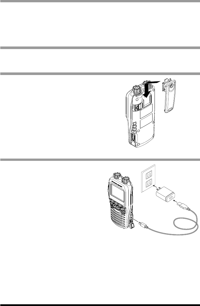
Belt Clip Installation / Removal
1. To install, align the Belt Clip Clip-22 to the
groove of the rear panel, then press the
Belt Clip downward until it locks in place
with a “Click”.
2. To remove, pull the Clip-22 tab away from
the real panel to unlock the Clip-22, then
slide the Clip-22 upward to remove it.
Battery Charging
If the battery has never been used, or its
charge is depleted, charge the RAM4W
according to the following procedures:
1. Turn the RAM4W off.
2. Slide the USB cover button (with arrow)
up to open the cover, then connect the
supplied Charge Cable to the USB jack.
3. Connect the other side plug of the
supplied Charge Cable to the SAD-17
then plug the SAD-17 into the AC line
outlet.
4. If the connection is correct, the RAM4W’s
LCD display will show the battery
charging icon.
5. A fully-discharged RAM4W will be
charged completely in approximately 4
hours.
When charging is completed, the battery
charging icon will disappear.
Application for FCC / IC
FCC ID: K660A290X10 / IC: 511B-0A290X10
5SSM-71H Instruction Manual
CAUTION
Waterproof and oating features of the RAM4W are assured only when the USB
jack cover is locked completely.
The SAD-17 is NOT designed to be waterproof. Charge the radio in a dry location.
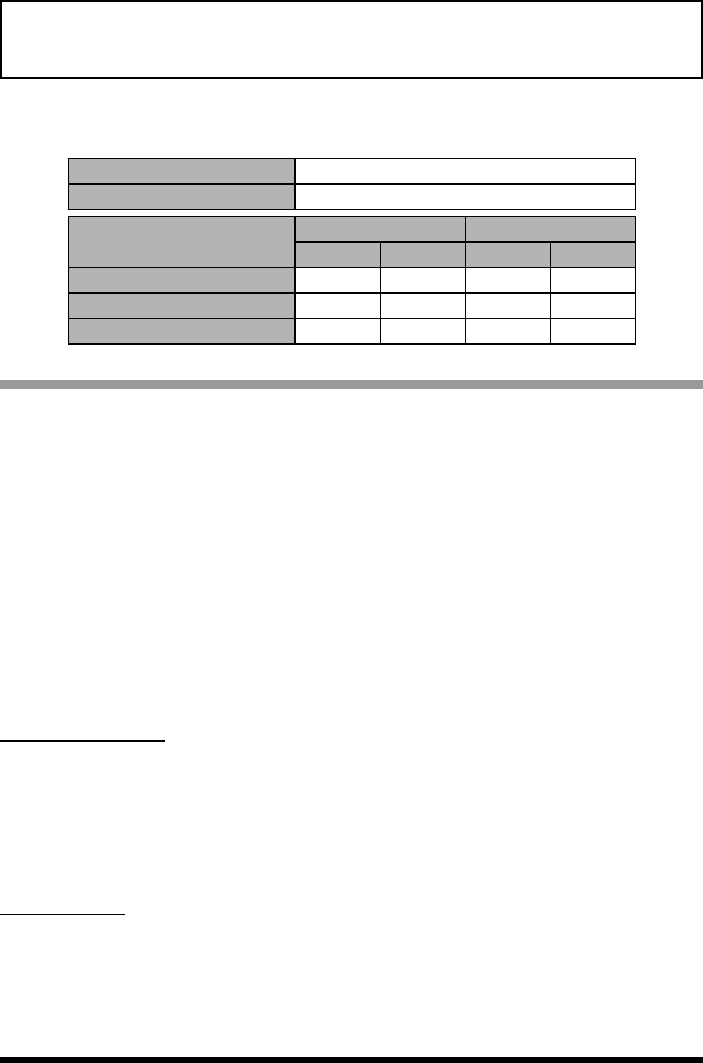
The RAM4W is equipped with a high-performance Lithium Battery.
Built-in Lithium-ion Battery
Capacity 1800 mAh
Nominal Voltage 7.4 V
Temperature Range Minimum Maximum
°C °F °C °F
Charge 541 35 95
Discharge –20 –4 60 140
Storage –10 14 35 95
Battery Safety
Battery packs for your equipment contain Li-ion batteries. This type of battery stores
a charge powerful enough to be dangerous if misused or abused, especially when
removed from the equipment. Please observe the following precautions:
DO NOT SHORT BATTERY PACK TERMINALS: Shorting the terminals that power
the equipment can cause sparks, severe overheating, burns, and battery cell damage.
If the short is of sufcient duration, it is possible to melt battery components. Do not
place a loose battery pack on or near metal surfaces or objects such as paper clips,
keys, tools, etc. When the battery pack is installed on the transceiver, the terminals that
transfer current to the transceiver are not exposed. The terminals that are exposed on
the battery pack when it is mounted on the transceiver are charging terminals only and
do not constitute a hazard.
DO NOT INCINERATE: Do not dispose of any battery in a re or incinerator. The heat of
re may cause battery cells to explode and/or release dangerous gases.
Battery Maintenance
For safe and proper battery use, please observe the following:
Battery packs should be charged only in non-hazardous environments.
Use only STANDARD HORIZON-approved batteries.
Use only a STANDARD HORIZON-approved charger. The use of any other charger
may cause permanent damage to the battery.
Follow charging instructions provided with the chargers.
Battery Storage
Store the batteries in a cool place to maximize storage life. Since batteries are subject
to self-discharge, avoid high storage temperatures that cause large self-discharge rates.
After extended storage, a full recharge is recommended.
Application for FCC / IC
FCC ID: K660A290X10 / IC: 511B-0A290X10

6SSM-71H Instruction Manual
Battery Recycling
DO NOT PLACE USED BATTERIES IN YOUR REGULAR TRASH!
LI-ION BATTERIES MUST BE COLLECTED, RECYCLED OR DISPOSED OF IN AN
ENVIRONMENTALLY SOUND MANNER.
The incineration, land filling or mixing of Li-ion batteries with the
municipal solid waste stream is PROHIBITED BY LAW in most areas.
Return batteries to an approved Li-ion battery recycler. This may be
where you purchased the battery.
Contact your local waste management officials for other information
regarding the environmentally sound collection, recycling and disposal
of Li-ion batteries.
Pairing
When using the RAM4W for the rst time, the RAM4W and the Wireless Access Point
SCU-30 must be paired. Refer to the Transceiver’s Operating Manual for Pairing
instructions.
1. Please bring the RAM4W and the SCU-30 close together when doing Pairing.
2. Press and hold [16/S] key and turn on the RAM4W.
3. Press and hold [16/S] key and turn on the transceiver.
“Searching ...” appears on the LCD.
4. When pairing is completed, the display will appears “Complited”.
Application for FCC / IC
FCC ID: K660A290X10 / IC: 511B-0A290X10
7SSM-71H Instruction Manual
THIS DEVICE COMPLIES WITH PART 15 OF THE FCC RULES. OPERATION
IS SUBJECT TO THE FOLLOWING TWO CONDITIONS: (1) THIS DEVICE MAY
NOT CAUSE HARMFUL INTERFERENCE, AND (2) THIS DEVICE MUST ACCEPT
ANY INTERFERENCE RECEIVED, INCLUDING INTERFERENCE THAT MAY
CAUSE UNDESIRED OPERATION.
Changes or modications to this device not expressly approved by YAESU U.S.A.
could void the User’s authorization to operate this device.
This device complies with Industry Canada license-exempt RSS standard(s).
Operation is subject to the following two conditions: (1) this device may not
cause interference, and (2) this device must accept any interference, including
interference that may cause undesired operation of the device.
Le présent appareil est conforme aux CNR d’Industrie Canada applicables aux
appareils radio exempts de licence. L’exploitation est autorisée aux deux conditions
suivantes : (1) l’appareil ne doit pas produire de brouillage, et (2) l’utilisateur de
l’appareil doit accepter tout brouillage radioélectrique subi, même si le brouillage
est susceptible d’en compromettre le fonctionnement.
FCC Notice
This equipment has been tested and found to comply with the limits for a Class
B digital device, pursuant to Part 15 of the FCC Rules. These limits are designed
to provide reasonable protection against harmful interference in a residential
installation. This equipment generates, uses and can radiate radio frequency
energy and, if not installed and used in accordance with the instructions, may
cause harmful interference to radio communications. However, there is no guar-
antee that interference will not occur in a particular installation. If this equipment
does cause harmful interference to radio or television reception, which can be
determined by turning the equipment off and on, the user is encouraged to try to
correct the interference by one or more of the following measures:
Reorient or relocate the receiving antenna.
Increase the separation between the equipment and receiver.
Connect the equipment into an outlet on a circuit different from that to which
the receiver is connected.
Consult the dealer or an experienced radio/TV technician for help.
Unauthorized changes or modications to this equipment may void compliance
with FCC Rules. Any change or modication must be approved in writing by
STANDARD HORIZON.
Application for FCC / IC
FCC ID: K660A290X10 / IC: 511B-0A290X10

8SSM-71H Instruction Manual
Specications
Supply Voltage: 3.7 VDC
Current Consumption: 450 mA @VOL Max.
100 mA @AF Mute
Operating Temperature: –4 °F to +140 °F (–20 °C to +60 °C)
Wireless Networking Module: FCC ID: K660A290910, IC: 511B-0A290910
Frequency Band: 2.4 GHz
Wireless Networking Standard: IEEE 802.11 b/g/n
AF output: 700 mW @ 8 ohms for 10 % THD
Display Size: 1.8” x 0.9” (45 x 23 mm)
Display Resolution: 222 x 162 dots
Dimensions (WxHxD): 2.5” x 5.3” x 1.3” (63 x 135 x 32.5 mm)
Weight (Approx): 7.23 oz (205 g)
Symbol placed on the equipment
Direct Current
Application for FCC / IC
FCC ID: K660A290X10 / IC: 511B-0A290X10

9SSM-71H Instruction Manual
Disposal of Electrical and Electronic Equipment
Products with the symbol (crossed-out wheeled bin) cannot be disposed as
household waste.
Electronic and Electrical Equipment should be recycled at a facility capable of
handling these items and their waste byproducts.
Please contact a local equipment supplier representative or service center for
information about the waste collection system in your country.
Application for FCC / IC
FCC ID: K660A290X10 / IC: 511B-0A290X10
Printed in Japan
YAESU MUSEN CO., LTD.
All rights reserved.
No portion of this manual may be
reproduced without the permission of
YAESU MUSEN CO., LTD.
YAESU MUSEN CO., LTD.
Tennozu Parkside Building
2-5-8 Higashi-Shinagawa, Shinagawa-ku, Tokyo 140-0002 Japan
YAESU USA
6125 Phyllis Drive, Cypress, CA 90630, U.S.A.
YAESU UK
Unit 12, Sun Valley Business Park, Winnall Close
Copyright 2017
Application for FCC / IC
FCC ID: K660A290X10 / IC: 511B-0A290X10