Yaesu Musen 0A290X10 WI-FI REMOTE MICROPHONE User Manual OM
Yaesu Musen Co., Ltd. WI-FI REMOTE MICROPHONE OM
UserManual.wiki
>
Yaesu Musen
>
0A290X10 User Manual
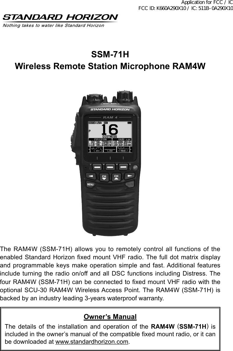
Operating Manual
Navigation menu
Upload a User Manual
Namespaces
Wiki Guide
HTML
PDF
Info
Views
User Manual
Discussion / Help
Navigation
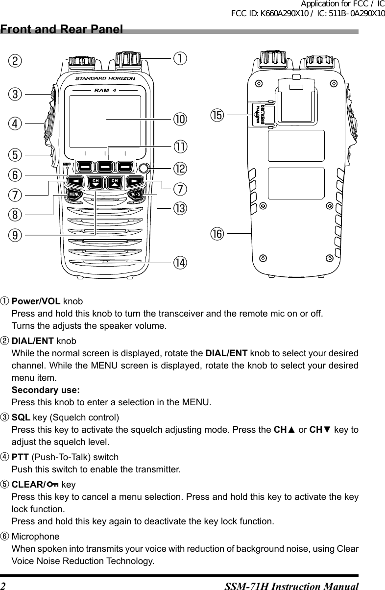
![3SSM-71H Instruction Manual Note: Position your mouth about 1/2” (1.5 cm) away from the microphone hole and speak in a normal voice.⑦ ◄/► key Press these keys to switch the function menu. Secondary use: While the MENU screen is displayed, press the key to slide the on-screen menu to the right/left side.⑧ MENU key Press this key to access the MENU.⑨ CH▼/CH▲ key These keys are used to change the operating channel. Press the key momentarily, the channel increases/decreases one step. Holding the key, the channel increases/decreases continuously. Secondary use: While the MENU screen is displayed, press the key to slide the on-screen menu upward/downward. When in the PA or Fog mode, press the key to change the channel.⑩ Display 222 by 162 pixels full dot matrix display.⑪ Soft keys These three programmable keys can be customized through the setup menu mode. When pressing one of these keys briey, the key functions will appear at the bottom of the display.⑫ Strobe Light When the [STROBE] soft key is pressed, the internationally-recognized Morse Code “S.O.S” message will light and ash repeatedly. From MENU → SETUP → CONFIGURATION → STROBE LED, you can select one option from “CONTINUOUS”, “SOS”, “BLINK 1”, “BLINK 2” and “BLINK 3”.⑬ 16/S key Pressing this key immediately recalls channel 16 from any channel location. Holding down this key recalls the SUB channel (The default setting is channel 9). Pressing this key again reverts to the previous selected working channel.⑭ Speaker The internal speaker is located here.⑮ DISTRESS key This key is used to send a DSC distress call.⑯ USB jack Use the micro USB type B jack for SSM-71H (RAM4W) battery charge. Note: When the DATA jack is securely covered with rubber cap, the SSM-71H meets the waterproong performance.Application for FCC / IC FCC ID: K660A290X10 / IC: 511B-0A290X10](https://usermanual.wiki/Yaesu-Musen/0A290X10/User-Guide-3522382-Page-3.png)
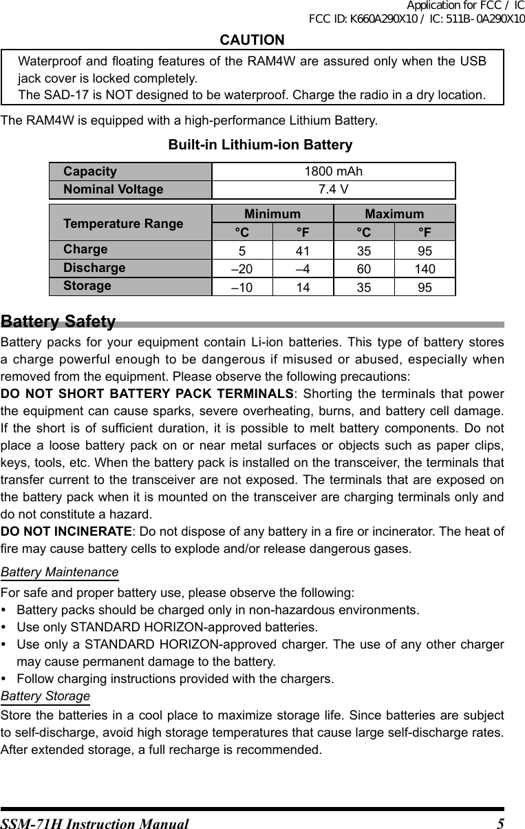
![6SSM-71H Instruction ManualBattery RecyclingDO NOT PLACE USED BATTERIES IN YOUR REGULAR TRASH!LI-ION BATTERIES MUST BE COLLECTED, RECYCLED OR DISPOSED OF IN AN ENVIRONMENTALLY SOUND MANNER.The incineration, land filling or mixing of Li-ion batteries with the municipal solid waste stream is PROHIBITED BY LAW in most areas.Return batteries to an approved Li-ion battery recycler. This may be where you purchased the battery.Contact your local waste management officials for other information regarding the environmentally sound collection, recycling and disposal of Li-ion batteries.PairingWhen using the RAM4W for the rst time, the RAM4W and the Wireless Access Point SCU-30 must be paired. Refer to the Transceiver’s Operating Manual for Pairing instructions.1. Please bring the RAM4W and the SCU-30 close together when doing Pairing.2. Press and hold [16/S] key and turn on the RAM4W.3. Press and hold [16/S] key and turn on the transceiver.“Searching ...” appears on the LCD.4. When pairing is completed, the display will appears “Complited”.Application for FCC / IC FCC ID: K660A290X10 / IC: 511B-0A290X10](https://usermanual.wiki/Yaesu-Musen/0A290X10/User-Guide-3522382-Page-6.png)