Yaesu Musen 10444140 Rack Mount Repeater User Manual VXR 9000 p65
Yaesu Musen Co., Ltd. Rack Mount Repeater VXR 9000 p65
UserManual.wiki
>
Yaesu Musen
>
10444140 User Manual
Users Manual
Navigation menu
Upload a User Manual
Namespaces
Wiki Guide
HTML
PDF
Info
Views
User Manual
Discussion / Help
Navigation
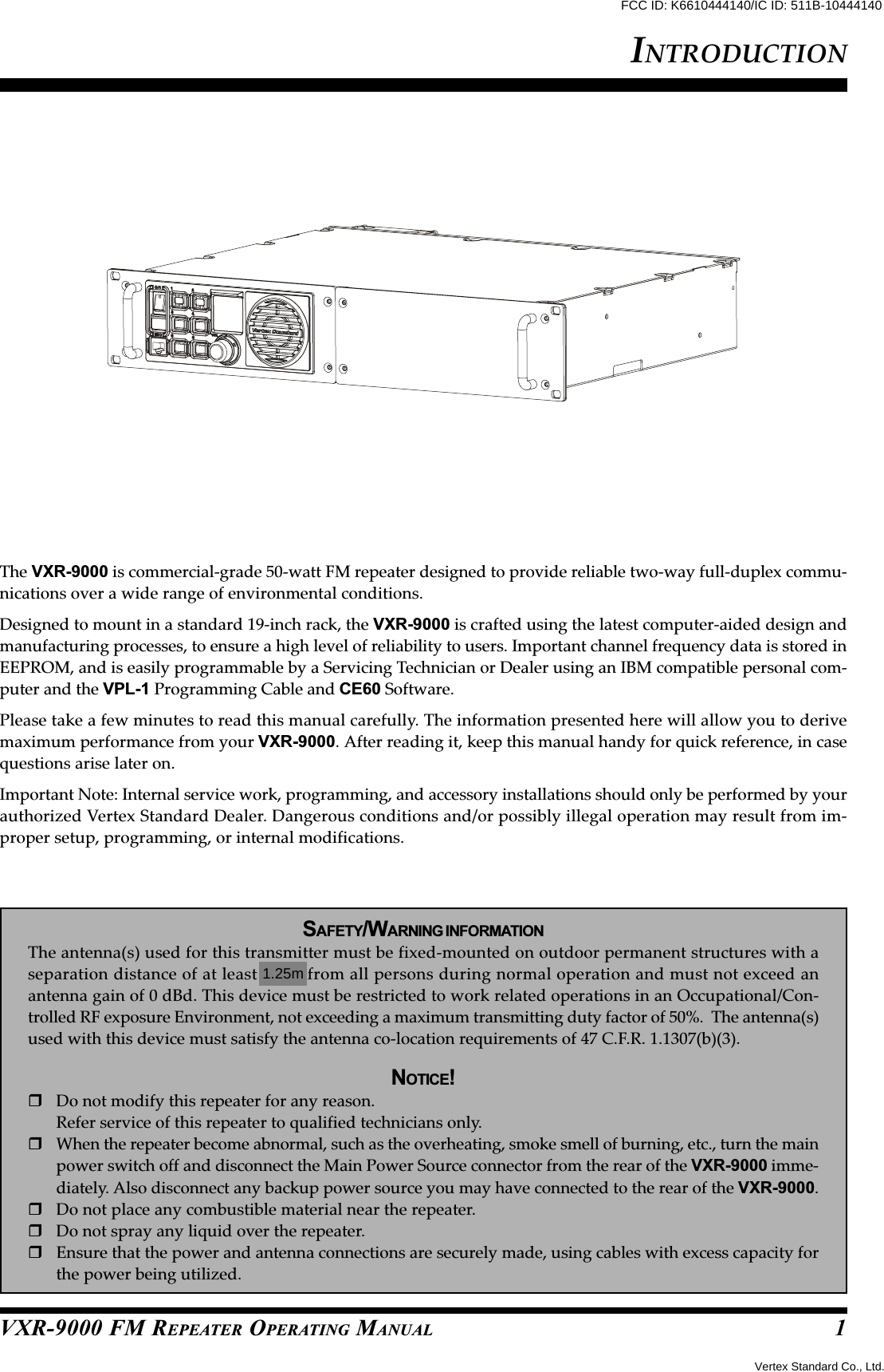
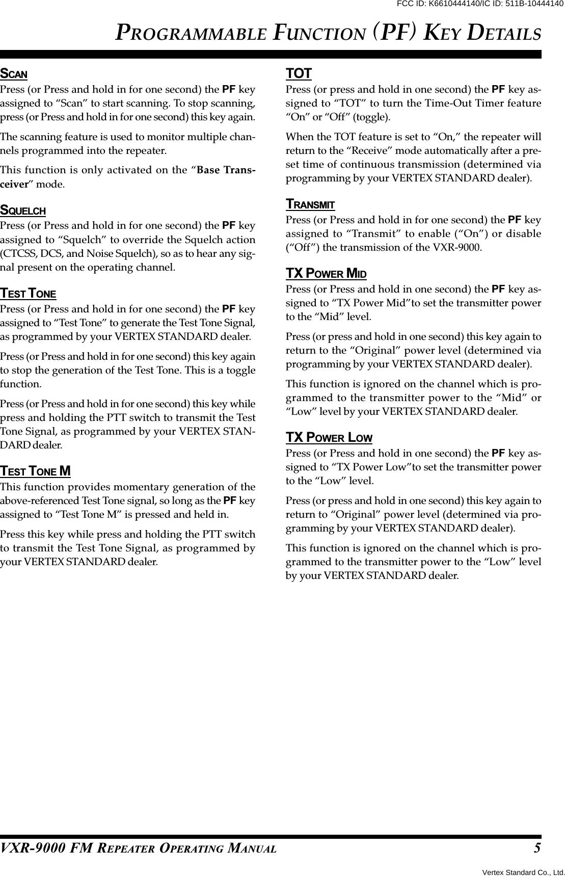
![VXR-9000 FM REPEATER OPERATING MANUALDB-25 CONNECTOR PORTThe VXR-9000 repeater is provided with a 25-pin DB-25F female connector for interconnections toaccessories.Use a DB-25M 25-pin male connector to con-nect accessories to the repeater. The pins on the acces-sory connector are explained in detail as follows:Pin 1: GNDChassis ground for all logic levels and power supplyreturn.Pin 2: +13.6 V[POWER SUPPLY]This pin provides 13.6 Volts, 2.0 A, DC from the repeatersupply. There is a internal 3 A fuse to prevent damageto the repeater.Pin 3: TX AF IN[ANALOG TRANSMITTER INPUT] (VOICE BAND: 300 ~ 3,000 HZ)This pin is audio input. Input impedance is 600 Ohms.This audio is injected before the splatter filter stage, soexcess signal input levels are clipped.Use shielded cable to connect to this pin, and connectthe shield to GND.Pin 4: TONE IN[TRANSMITTER INPUT] (SUB-AUDIBLE BAND: 5 ~ 250 HZ)This pin is sub-audiable tone input. The input imped-ance is 600 Ohms, and has a flat response characteristic(repeater deviation is constant for a given signal levelover the frequency range of 5 ~ 250 Hz). Injecting toohigh a voltage here causes over-deviation of CTCSS orDCS, degrading performance.Use shielded cable to connect to this pin, connecting theshield to GND.Pin 5: TX ATTThis output is intended for controlling an external co-axial switching relay. It is an open drain output whichcan sink approx. 1.5 A when active. The delay timewhich is between the repeater cause to transmit modeand this port switches to ground can be programmedby your VERTEX STANDARD dealer.Pin 6: DISC OUT[ANALOG OUTPUT] (WIDE-BAND: 0 ~ 3,000 HZ)Received signals with full system deviation produce350 mVrms audio at this pin. The output impedance is600 Ohm, and is extracted before the de-emphasis andsquelch circuitry. Use shielded cable to connect to thispin, and connect the shield to GND.Pin 7: N.C.No connection.Pin 8: RSSI[ANALOG OUTPUT]A DC voltage proportional to the strength of the signalcurrently being received (Receiver Signal Strength In-dicator) is provided on this pin. This low impedanceoutput is generated by the receiver IF sub-system andbuffered by an internal op-amp. Typical voltages aregraphed as follows:DB-25 PIN NUMBERING70–60 –100 –110 –120 (dBm)–70 –80 –900.51.01.52.02.5(DC V)Input Signal LevelRSSI Output VoltagePin 9: COAX. SW[LOGIC OUTPUT (ACTIVE LOW)]This output is intended for controlling an external co-axial switching relay. It is an open drain output whichcan sink approx. 1.5 A when active. This signal onlyswitches if the repeater has been programmed for “SIM-PLEX” mode. If programmed for “DUPLEX,” the signalremains open (high impedance) at all time.Vertex Standard Co., Ltd.FCC ID: K6610444140/IC ID: 511B-10444140](https://usermanual.wiki/Yaesu-Musen/10444140/User-Guide-568935-Page-9.png)
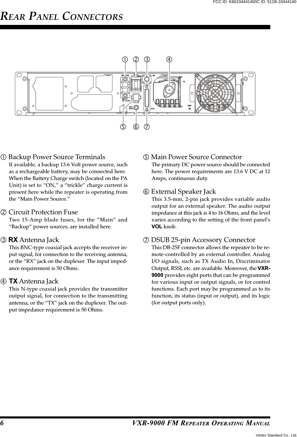
This pin is an output for low speed receiving data sig-nals (typically 1200 bps), with the data being extractedafter the de-emphasis and low pass filter stages.Pin 23: RXD HIGH[DIGITAL OUTPUT FOR DATA COMMUNICATIONS](Max.: 5 kHz)This pin is an output for high speed receiving data sig-nals (typically 9600 bps), with the data being extractedimmediately after the discriminator (prior to any de-emphasis).Pin 24: TXD LOW[ANALOG INPUT FOR DATA COMMUNICATIONS](300 ~ 3,000 Hz)This pin is intended to be used as a low speed datasignal input to the repeater (typically 1200 bps). Thisdigital data signal is injected before the transmitter pre-emphasis and limiting stages, so excess signal inputlevels are clipped.Pin 25: TXD HIGH[DIGITAL INPUT FOR THE DATA COMMUNICATIONS](0 ~ 5 kHz)This pin is intended to be used as a high speed digitaldata signal input to the repeater (typically 9600 bps).This digital data signal is injected after the transmittersplatter filter stage.DB-25 CONNECTOR PORT8Pin I/O Port10 613 715 416 317 218 119 021 5Vertex Standard Co., Ltd.FCC ID: K6610444140/IC ID: 511B-10444140](https://usermanual.wiki/Yaesu-Musen/10444140/User-Guide-568935-Page-10.png)