Yaesu Musen 10511070 Integrated HF Communications Transceiver User Manual p65
Yaesu Musen Co., Ltd. Integrated HF Communications Transceiver p65
UserManual.wiki
>
Yaesu Musen
>
10511070 User Manual
operating manual
Navigation menu
Upload a User Manual
Namespaces
Wiki Guide
HTML
PDF
Info
Views
User Manual
Discussion / Help
Navigation
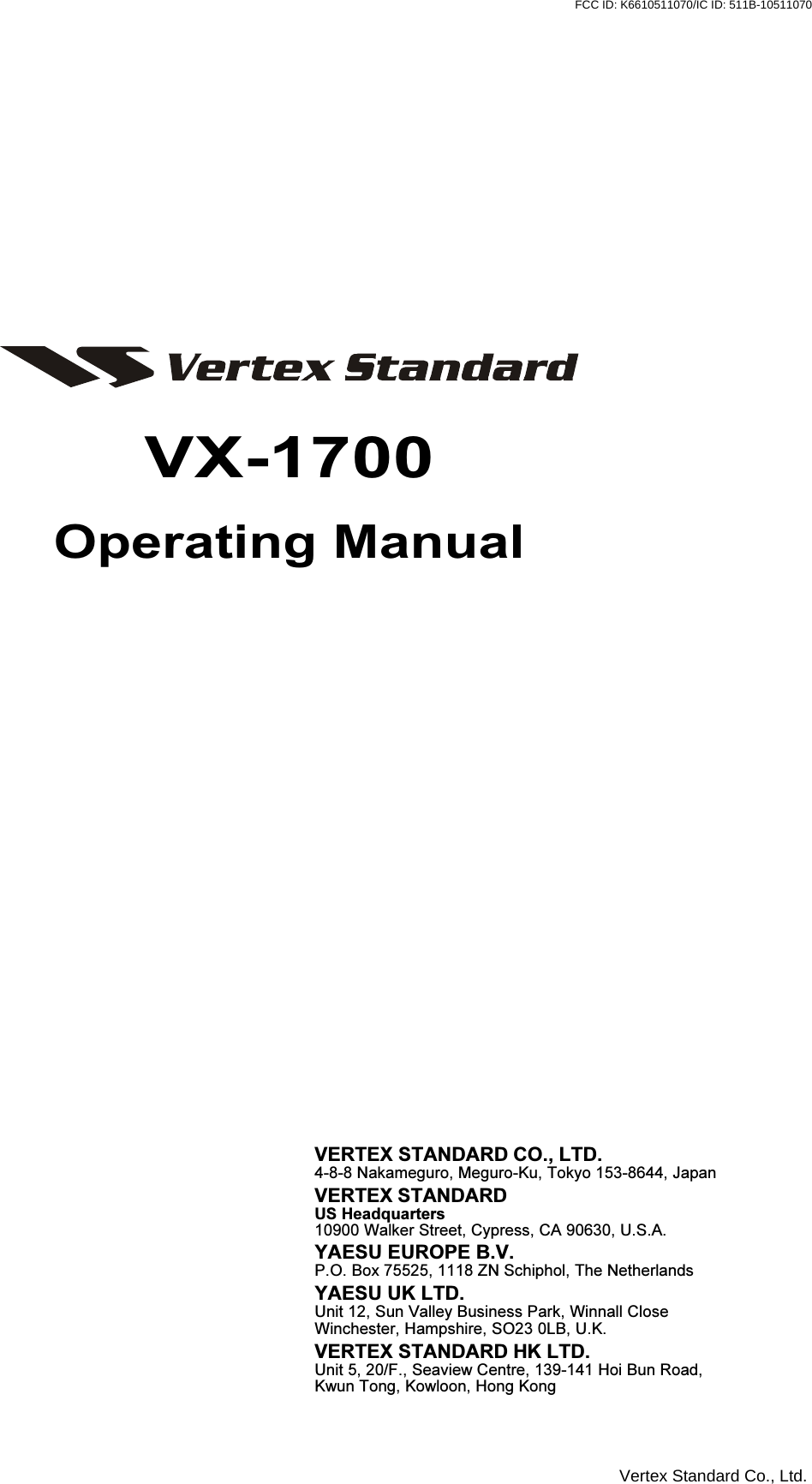
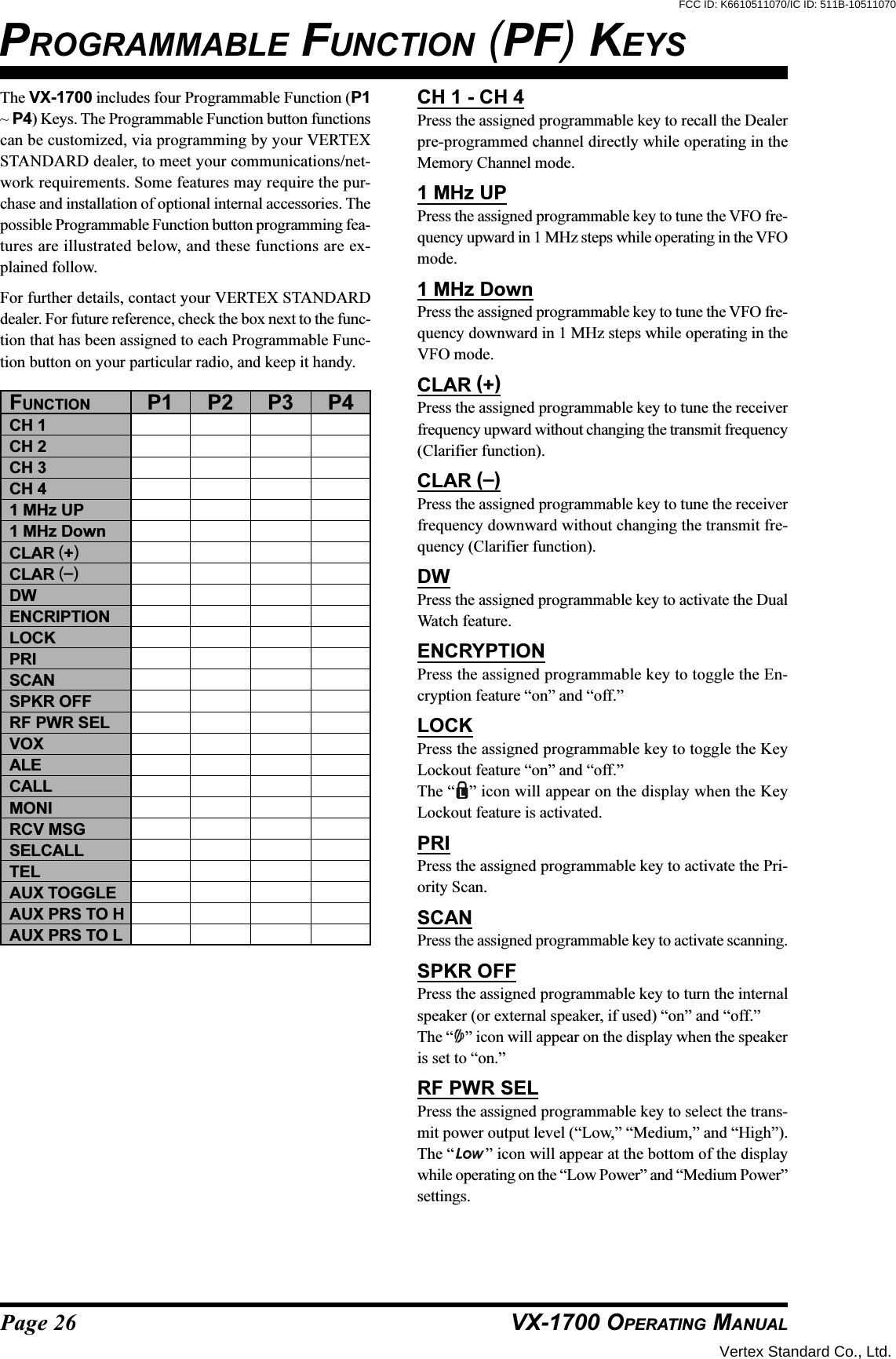
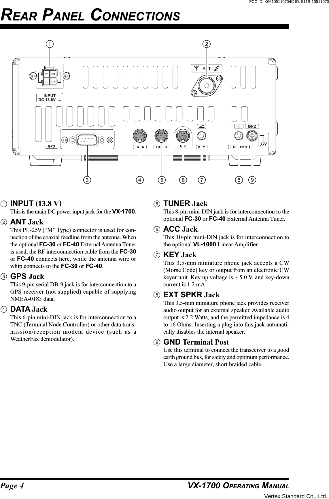
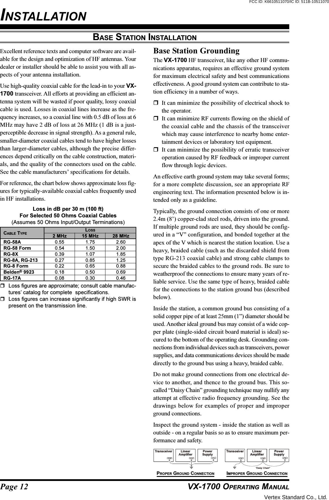
![Page 2 VX-1700 OPERATING MANUALMIC JackThis modular jack accepts microphone voice input,as well as scanning and PTT (Push To Talk) controlfrom the microphone. Specified microphone imped-ance is 500 - 600 Ohms.POWER SwitchThis is the main on/off switch for the VX-1700. Pressand hold this switch for one second to toggle thetransceiver’s power on and off.CH (Channel) Selector KnobThe Channel selector knob selects memory channels,and tunes the VFO at a rate of 30 steps per revolution.ALARM ButtonPressing this button activates the alarm generator, withthe alarm tone emanating from the speaker (receiveraudio is muted, and no transmission occurs). To trans-mit the alarm tone, press both the [ALARM] and the[2182] button (described next).2182 ButtonPressing this button places the VX-1700 in the “Emer-gency Channel” mode, with the following results:(A) The transceiver is instantly set to 2182 kHz in theH3E mode,(B) The “EMRG” notation appears on the LCD dis-play, indicating Emergency Channel Operation.VOL KnobThis control adjusts the receiver audio volume fromthe speaker. Clockwise rotation of this control in-creases the volume level.FRONT PANEL CONTROL & SWITCHESSQL KnobThis control may be used silence the receiver whenno signals are being received. Clockwise rotation ofthis control cause the receiver to respond only to pro-gressively stronger signals; conversely, counter-clock-wise rotation of this control allows progressivelyweaker signals to be heard.When a signal or noise breaks through the squelch“threshold,” the “ ” icon on the display will beilluminated.P1 - P4 Keys (PROGRAMMABLE FUNCTION KEYS)These four keys functions can be customized, via pro-gramming by your Vertex Standard dealer. The fac-tory defaults are shown below.P1 Key: Press this key to tune the receiver frequencydownward without changing the transmitfrequency (Clarifier function).P2 Key: Toggles the Key Lockout feature “on” and“off.”P3 Key: Press this key to tune the receiver frequencyupward without changing the transmit fre-quency (Clarifier function).P4 Key: Turns the internal speaker (or externalspeaker, if used) “on” and “off.”KeypadThese 12 keys are used for both frequency entry and/or certain operational commands.LCD DisplayThis multi function LCD (Liquid Crystal Display) in-cludes frequency readout or Alpha/Numeric “Tag”labeling of the channel in use, plus a Signal Strength/Power Output meter, and icons which provide visualconfirmation of transceiver status.SpeakerThe internal speaker is located here.Vertex Standard Co., Ltd.FCC ID: K6610511070/IC ID: 511B-10511070](https://usermanual.wiki/Yaesu-Musen/10511070/User-Guide-602112-Page-4.png)
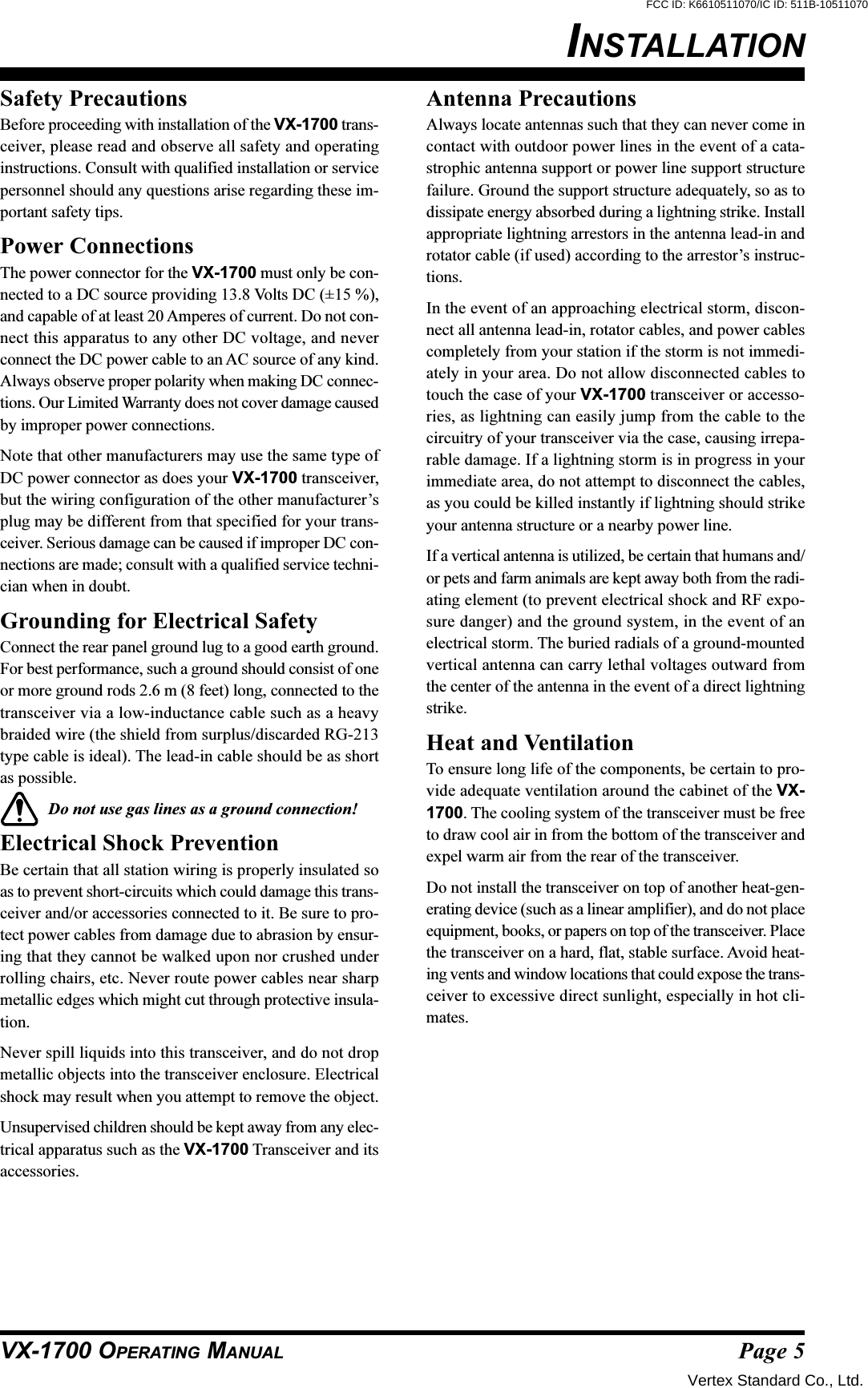
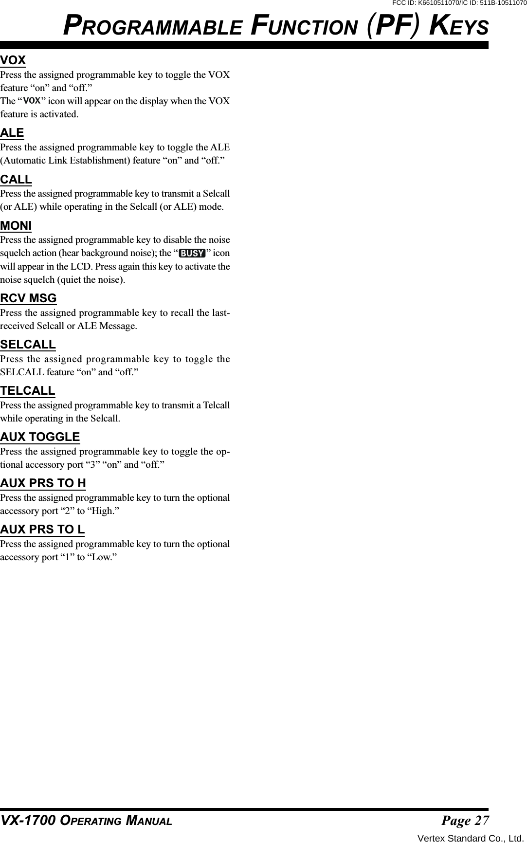
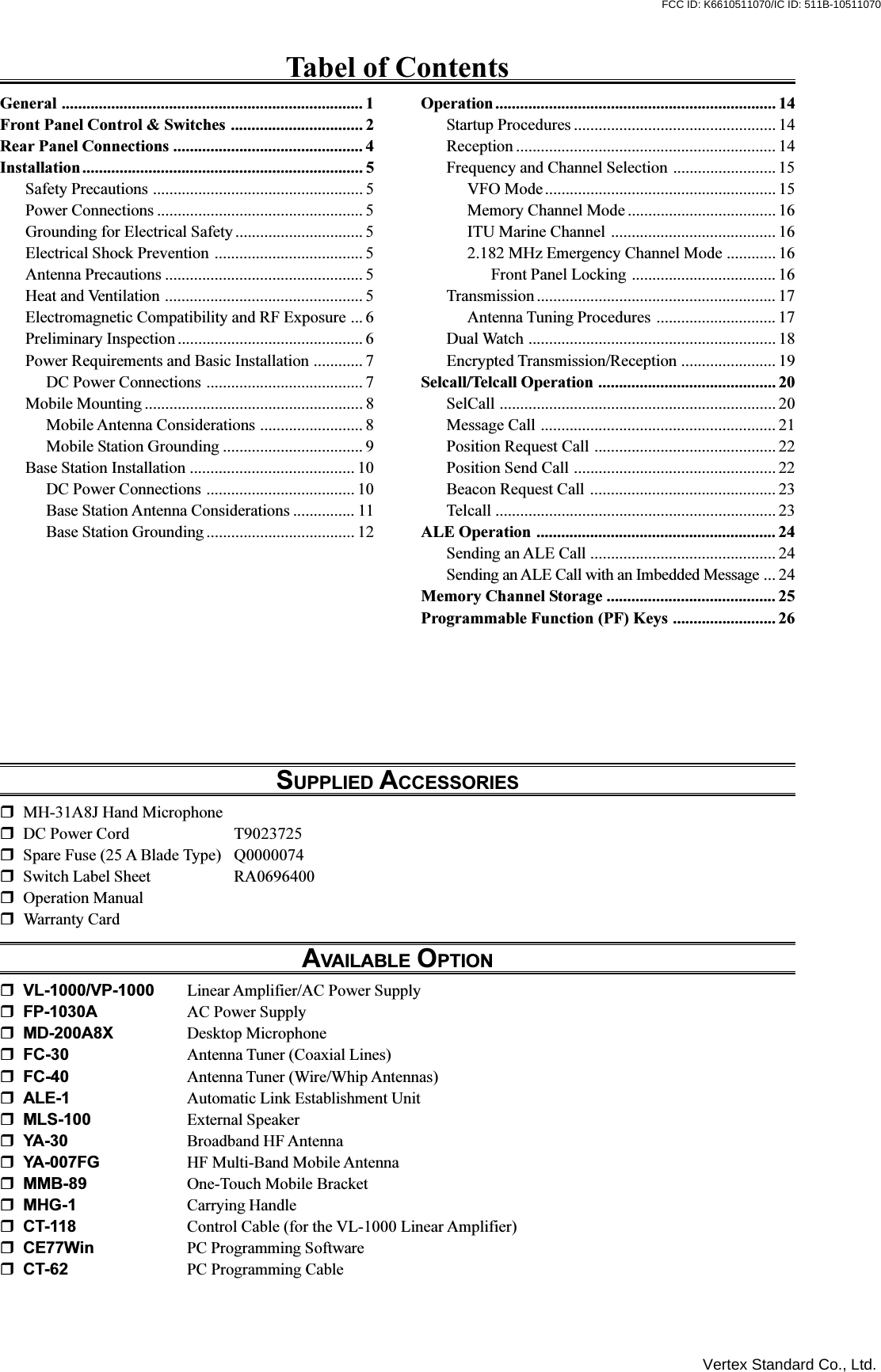
 key to reduce the noise level. Whenthe noise blanker is activated, the “ ” icon will beilluminated. Press the [2(NB)] key again to disable thenoise blanker.If the station you are listening to should drift or other-wise be unclear (the voice may sound too high-pitchedor too low-pitched), pressing the [P1] or [P3] key mayimprove the sound of the incoming signal. The [P1]/[P3] key function does not affect your transmissionfrequency; only the receive frequency is being adjusted.When the receiving frequency is higher than displayedfrequency, the “” icon will appear to the right of thefrequency display. Similarly, when the receiving fre-quency is lower than displayed frequency, the “” iconwill appear to the right of the frequency display. Pressand hold in both [P1] and [P3] keys for one second toreset the offset.If the LCD display is too bright, press the keypad’s[0(DIM)] key to reduce the display brightness. Pressthe [0(DIM)] key again return to the LCD display tonominal brightness level.To turn the internal speaker (or external speaker, if used)off, press the [P4] key. Press the [P4] key again torestore the speaker audio.Vertex Standard Co., Ltd.FCC ID: K6610511070/IC ID: 511B-10511070](https://usermanual.wiki/Yaesu-Musen/10511070/User-Guide-602112-Page-16.png)
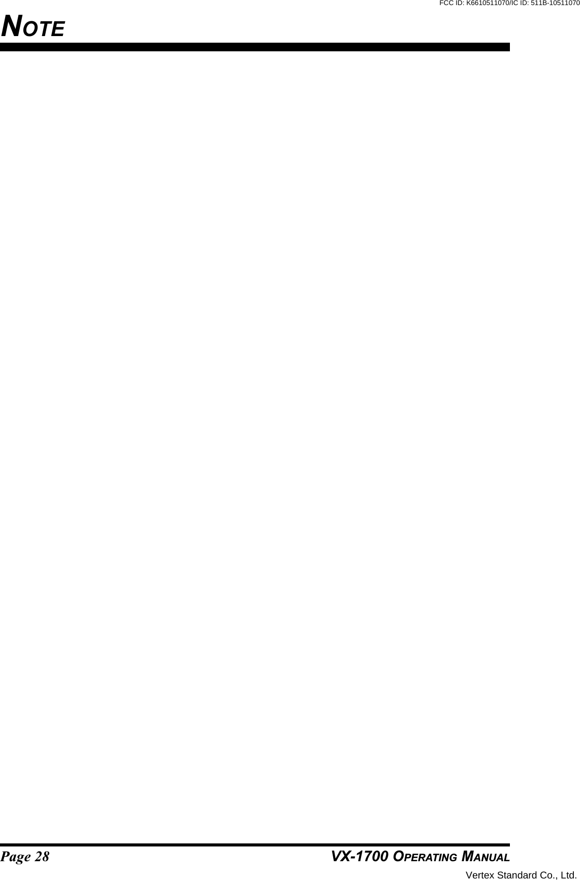
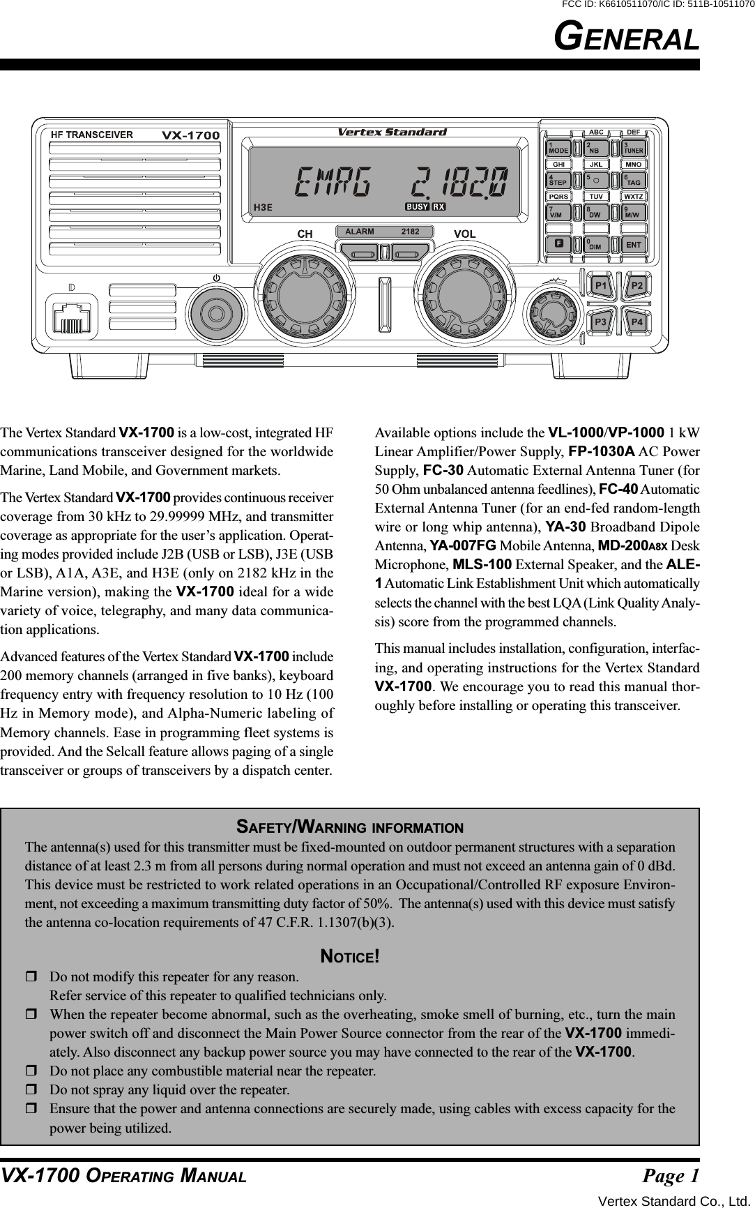
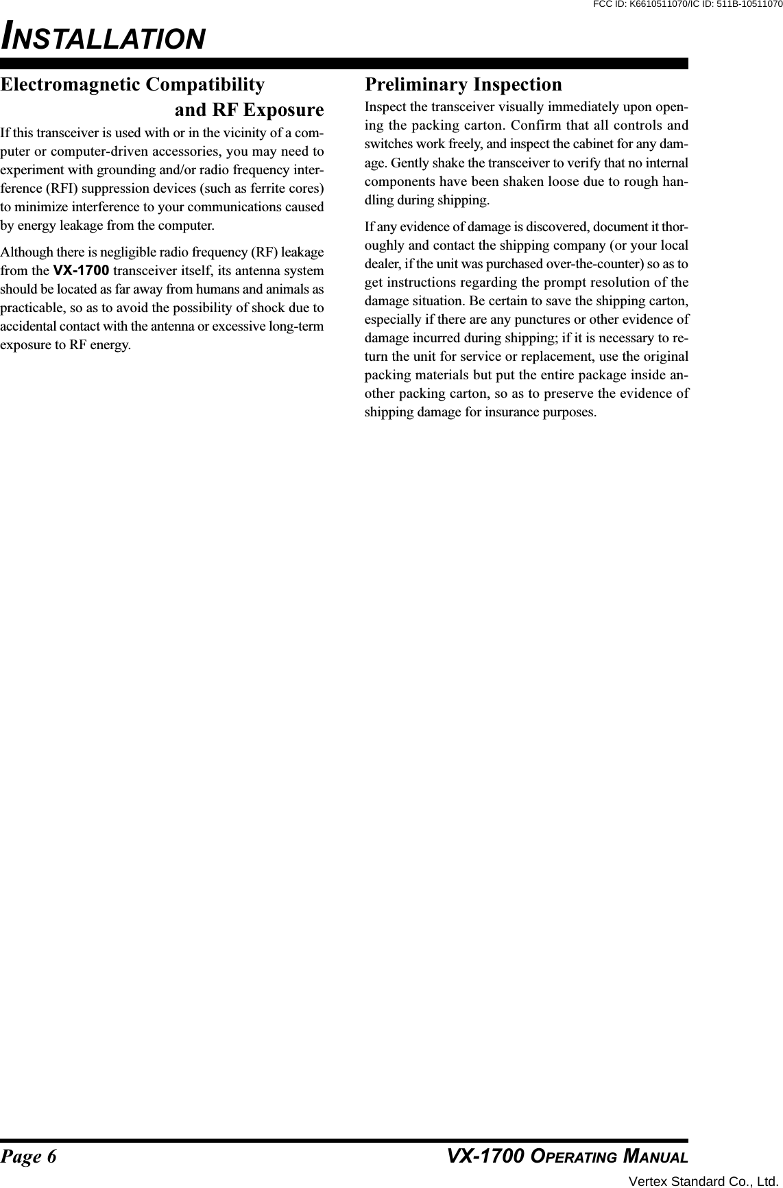
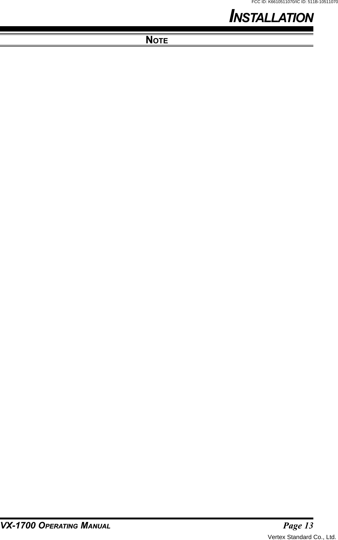
![Page 15VX-1700 OPERATING MANUALOPERATIONFREQUENCY AND CHANNEL SELECTIONThe VX-1700 includes the following frequency selectioncapabilities:A VFO (Variable Frequency Oscillator) SystemITU Marine ChannelMemory ChannelA one-touch (2.182 MHz) Emergency ChannelMemory, which places the transceiver on 2.182MHz (in transceivers configured for Marine use).In the VFO mode, the frequency is displayed on theright side, with the operating mode icon being displayedat the left edge of the display. On the left side of thedisplay, the current synthesizer step size is displayed.In the ITU mode, the frequency and operating modeare displayed as they are during VFO operation; how-ever, the left side of the display indicates the ITU Ma-rine Channel designator.In the Memory Channel Mode, the memory channelnumber is displayed on the left side of the display (forexample, 1-005). The digit to the left of the hyhen isthe Memory Bank Number, while the digits to the rightare the Channel Numbers within that bank. Therefore,in the example below, the display is indicating Chan-nel #5 on Memory Bank #1.In the Emergency Mode, the frequency “2.182.0” isdisplayed on the right side, with the special Alpha Tag“EMRG.”Frequency and channel selection are very simple on theVX-1700:Select the desired channel grouping (VFO, ITU, andMemory Channel) by repeatedly pressing the keypad’s[7(V/M)] key. The circulation of channel groups is VFO Memory Bank 1 Memory Bank 2 Memory Bank 3 Memory Bank 4 MemoryBank 4 ITU VFO …..VFO ModeRotate the CH Selector knob to select the operatingfrequency.If the tuning rate is too slow or too fast, the frequencysynthesizer steps may be changed by pressing thekeypad’s [4(STEP)] key. Available step sizes are 10Hz, 100 Hz, and 1 kHz.The microphone’s [UP] or [DWN] button may also beused to select the operating frequency. Pressing the UPor DWN button momentarily will cause the operatingfrequency to increment or decrement one step, respec-tively. Pressing and holding the [UP] or [DWN] but-ton in for 1/2 second will initiate upward or downwardscanning, respectively. Releasing the [UP] or [DWN]button halts the scan.The VFO frequency may be entered directly from thekeypad.Press the keypad’s [ENT] key momentarily, thenenter six digits of the desired operating frequency(the “10s of Hz” digit can not be entered, even if10 Hz steps are selected; this is a time saving fea-ture). If you make a mistake during frequency en-try, rotate the Channel Selector knob so as to causethe erroneous digit of the frequency to blink; now,press the correct number on the key pad, and con-tinue with the remainder of the frequency entry pro-cess.If you require split-frequency operation (differenttransmit/receive frequencies), press the [ENT] keymomentarily, then enter the six digits of the desiredtransmit frequency; otherwise (to transmit and re-ceive on the same frequency), skip to the next step.Press and hold in the [ENT] key for 1/2 second tofinalize the entry of the VFO frequency (frequen-cies).If you need to change the operating mode, press thekeypad’s [1(MODE)] key. Available operating modesare J3E(USB), J3E(LSB), J2B (USB), A1A(CW), andA3E(AM).Vertex Standard Co., Ltd.FCC ID: K6610511070/IC ID: 511B-10511070](https://usermanual.wiki/Yaesu-Musen/10511070/User-Guide-602112-Page-17.png)
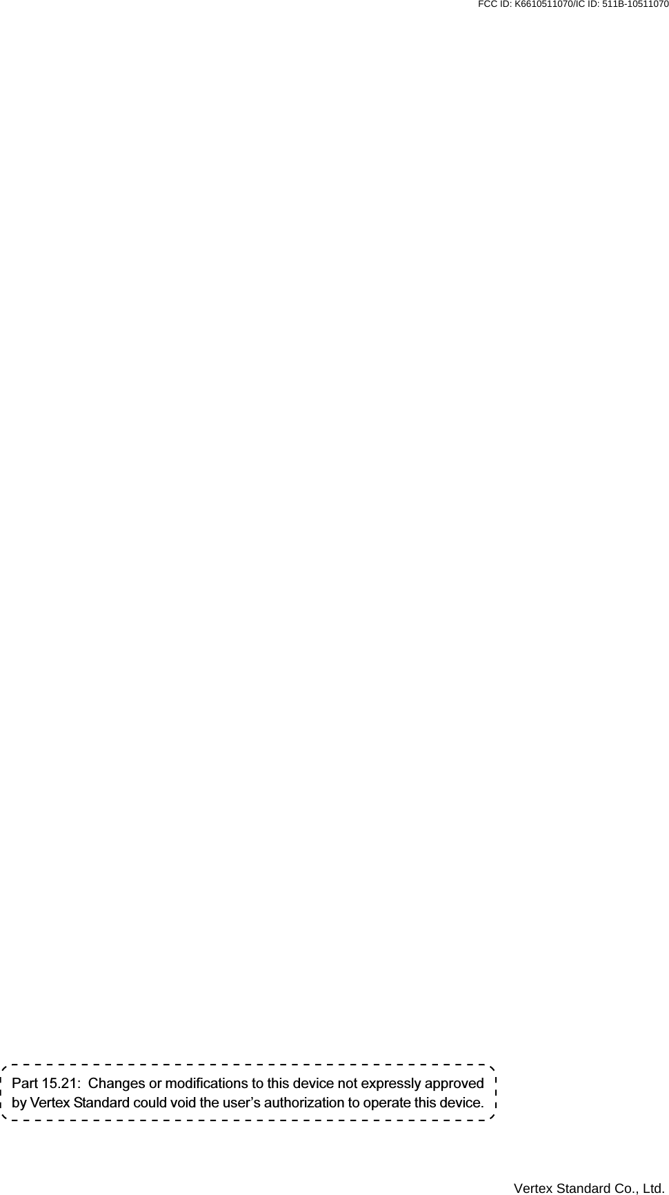
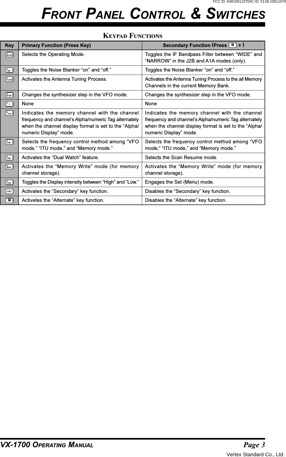
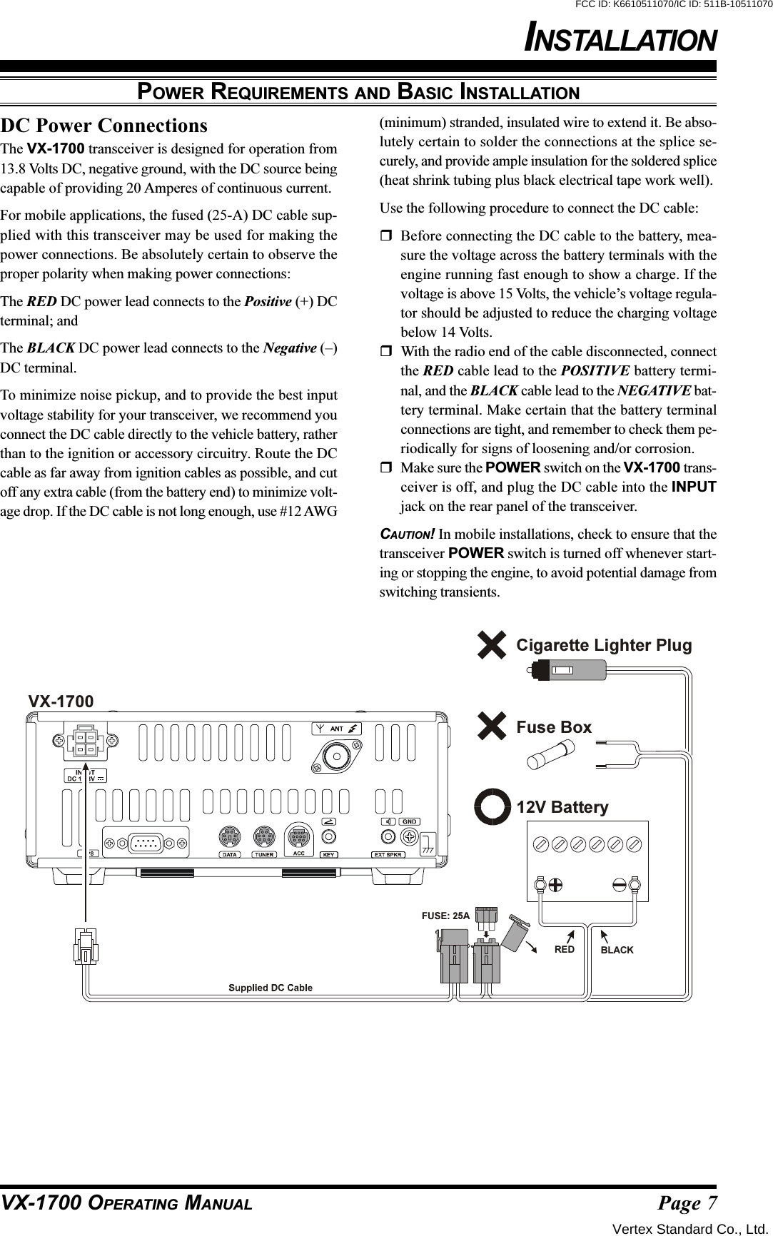
![Page 16 VX-1700 OPERATING MANUALFREQUENCY AND CHANNEL SELECTIONOPERATIONMemory Channel ModeRotate the CH Selector knob to select the desiredMemory Channel within the selected Memory Bank.Remember that there are a total of five Memory Banks,so if you do not find a particular channel, it may havebeen stored in a different Memory Bank.The microphone [UP] and [DWN] buttons may alsobe used to select the Memory Channel. Pressing the[UP] or [DWN] button momentarily will cause theMemory Channel to increment or decrement one step,respectively. Pressing and holding the [UP] or [DWN]button in for 1/2 second will initiate upward or down-ward scanning on the Memory Channels, respectively.Releasing the [UP] or [DWN] button halts the scan.ITU Marine ChannelRotate the CH Selector knob to select the desired ITUMemory Channel within the standard ITU MarineChannel Bank provided. The operating mode is auto-matically selected, and can not be changed.The microphone [UP] and [DWN] buttons may alsobe used to select the ITU Memory Channel. Pressingthe [UP] or [DWN] button momentarily will cause theITU Memory Channel to increment or decrement onestep, respectively. Pressing and holding the [UP] or[DWN] button in for 1/2 second will initiate upwardor downward scanning on the ITU Memory Channels,respectively. Releasing the [UP] or [DWN] button haltsthe scan.2.182 MHz Emergency Channel ModeA special Emergency Channel feature of the VX-1700 pro-vides several important operational benefits for the owner.Pressing the [2182] button automatically switches thetransceiver to the Marine Distress Channel, 2182 kHz(2.182 MHz), and also places the transceiver in theH3E (Single-Sideband AM) mode. On the display, thefrequency “2.182.0” will be displayed, as well as aspecial Alpha Tag “EMRG,” designating this as theEmergency Channel.If desired, the operating mode may be changed toJ3E(USB) by pressing the keypad’s [1(MODE)] key.The [ALARM] button may be used for sending a dis-tress signal. To test the alarm, just press the [ALARM]button momentarily. After one second, an audible alarmwill be heard, although no transmission occurs. Pressthe [ALARM] button again to stop the test alarm.In an Emergency, press the [2182] button while press-ing and holding in the [ALARM] button. This VX-1700will transmit the international marine distress signal(alternating 1300 Hz and 2200 Hz tones) for 35 sec-onds. Press the [ALARM] button (not the [2182] but-ton) to cancel the transmitted distress signal.Press the [2182] button again to exit the 2.182 MHzEmergency Channel Mode.Be certain your operators and crew understand the func-tion of the 2182 Alarm feature, and make sure theyunderstand that it is only to be used in case of a trueemergency situation.Front Panel LockingTo prevent inadvertent changing of the channel fre-quency or other front panel parameters, press the [P2]key on the front panel. All keys, and the Channel Se-lector knob, will locked out of the operational com-mand capability except for the POWER switch, the[ALARM] and [2182] buttons, and the [P2] key it-self. The “ ” icon will appear on the display.Press the [P2] key again to release the front panel tonormal operation.Vertex Standard Co., Ltd.FCC ID: K6610511070/IC ID: 511B-10511070](https://usermanual.wiki/Yaesu-Musen/10511070/User-Guide-602112-Page-18.png)
![Page 17VX-1700 OPERATING MANUALOPERATIONTRANSMISSIONFor Voice transmission, close the PTT (Push To Talk)switch on the microphone; the transmitter will now beactivated (note that the “ ” icon will be illuminatedon the LCD display). Hold the microphone about 1inch (25 mm) from your mouth, and speak into the frontof the microphone in a normal voice level. Release thePTT switch to return to the receive mode (the “ ”icon will be again illuminated, and the “ ” icon willgo out).For CW (Morse Code telegraphy) in the A1A mode,begin sending using your telegraph key or electronickeyer. The VX-1700 will automatically be placed inthe transmit mode when you start to send, and will re-vert to the receive mode when you stop sending. Asyou send, a “Sidetone” audio generator allows you tomonitor your sending.For Data transmission (including Morse Code telegra-phy using a TNC (Terminal Node Controller) and key-board, or similar computer-driven data transmissiondevices), transmit/receive control is exercised by thesoftware which accompanies the data transmissionequipment in use. See the User’s Manual for your ter-minal equipment for operating instructions. Remem-ber to follow the maximum power output guidelinesduring continuous-duty operation such as RTTY (Ra-dio Teletype) in the J2B mode. Adjust the TX Audiolevel from the TNC for a maximum of 50 Watts ofpower output (5 or 6 segments illuminated on the PowerOutput Bar Graph) if long periods of continuous trans-mission are anticipated.Antenna Tuning ProceduresWhen the optional FC-30 or FC-40 External AntennaTuner is installed, it is activated on each channel auto-matically.If the “ ” icon will appears at the upper right corner onthe LCD display while transmitting, the antenna systemmay require retuning. Use the following procedure.Be certain that all connections to the FC-30/-40 havebeen properly made.With the appropriate channel selected via the MainDial, press the keypad’s [3(TUNER)] key. The“” icon on the LCD Display will blink, andthe VX-1700 will transmit for a short time. Thereafter,the transceiver will return to the receive mode, and the“” icon will now be illuminated constantly.The FC-30/-40’s microprocessor-based circuitry in-cludes memory sufficient to retain 100 (for FC-30, 200for FC-40) antenna tuning settings in memory. Thiswill greatly reduce frequency change time. If you uti-lize more than 100 or 200 operating channels that arewidely removed in frequency, the new tuning settingswill be over-written on a first-in, first-out basis.Vertex Standard Co., Ltd.FCC ID: K6610511070/IC ID: 511B-10511070](https://usermanual.wiki/Yaesu-Musen/10511070/User-Guide-602112-Page-19.png)
![Page 18 VX-1700 OPERATING MANUALDUAL WATCHThe Dual Watch feature allows the user or dispatcher tooperate on one channel while periodically making a briefcheck of Memory Channel “1-001” (Memory Bank #1,Channel #1). The Dual Watch feature can be engaged solong as there is frequency and mode data written intomemory channel “1-001.”Every four seconds, the transceiver will automaticallyswitch over to memory channel “1-001.” If a station istransmitting on memory channel “1-001,” one of two thingswill happen:If the VX-1700 is in the “Carrier Drop” mode, the trans-ceiver will hold on memory channel “1-001” until thetransmission ceases. The transceiver will continue tohold for ten seconds after the transmission ends, in casethe other station decides to resume transmitting. Afterthe three second delay, Dual Watch will resume, withyour original operating channel (not memory channel“1-001”) being restored to the Main Display.If the VX-1700 is set to the “Time Delay” mode, thetransceiver will hold on memory channel “1-001” forfive seconds, then Dual watch operation will resume(irrespective of the transmit/receive status of any sta-tions on memory channel “1-001”).Dual Watch operation is simple to use.Follow these steps:First, set the desired “Resume” mode for Dual Watch.Usually, this will be “Carrier Drop,” which will notallow the transceiver to move off memory channel 1-01 if someone is still transmitting. To do this, press the[F] key followed by the [8(DW)] key, then rotate theCH Selector knob until “CARR” is shown in the LCDdisplay. If you prefer the “Time Delay” mode, rotatethe CH Selector knob until “TIME” is displayed. Nowpress the [8(DW)] key again to return to the normaldisplay.Adjust the SQL control so that the “ ” icon dis-appears and the receiver is silenced.Press the [8(DW)] key to activate Dual Watch. Afterfour seconds, the transceiver will switch over tomemory channel “1-001,” and will stay there for 1/2seconds, thereafter returning to your original channel.If a call is received on memory channel “1-001” dur-ing Dual Watch operation, the transceiver will lock ontothat channel, then resume in accordance with the “Re-sume” mode selected previously.Press the [8(DW)] key again to disable the Dual Watchfeature. Operation will revert to your original operat-ing frequency.Note that your main operating channel can be changedduring Dual Watch operation, but you cannot changechannels while memory channel “1-001” is beingchecked for activity.OPERATIONVertex Standard Co., Ltd.FCC ID: K6610511070/IC ID: 511B-10511070](https://usermanual.wiki/Yaesu-Musen/10511070/User-Guide-602112-Page-20.png)
![Page 19VX-1700 OPERATING MANUALENCRYPTED TRANSMISSION/RECEPTION (REQUIRES AFTER-MARKETING ENCRYPTION MODULE)OPERATIONIf the transceivers you (and others in your communi-cation group) are using are equipped with the after-market Encryption Module, the Encryption mode maybe activated by pressing the [ENCR] key. The“” icon will become illuminated.To de-activate encryption, press the [ENCR] key again.If the signals of all the other stations in your communi-cations group have a severely distorted or “scrambled”sound, you may have accidentally de-activated yourtransceiver’s encryption mode. Pressing the [ENCR]key may allow recovery. However, if only one stationin your communications group sounds distorted or“scrambled,” it is possible that the encryption mode ofthat transceiver may have been accidentally turned off.Either the dispatcher or you may advise the other sta-tion by switching your encryption off and calling theother station in the non-encrypted mode. Rememberthat your transmissions will be sent in a non-encryptedformat, and will thus not be secure; limit your discus-sion to a brief advisory regarding the [ENCR] key onthe other station’s transceiver, then revert to encryptedoperation immediately by pressing the [ENCR] keyon your transceiver.Vertex Standard Co., Ltd.FCC ID: K6610511070/IC ID: 511B-10511070](https://usermanual.wiki/Yaesu-Musen/10511070/User-Guide-602112-Page-21.png)
![Page 20 VX-1700 OPERATING MANUALThe VX-1700’s Selcall feature provides six calling modes:SelcallThe Selcall mode allows you to make an individual/group call using the individual ID (Identification)number assigned for each transceiver.Message CallThe Message Call mode allows you to send a textmessage (up to 64 characters of text) to anotherstation.Position Request CallThe Position Request Call mode allows you to re-quest the position information of another station.Position Send CallThe Position Send Call mode allows you to sendyour own position information to another station.Beacon Request CallThe Beacon Request Call mode allows you to in-quire as to the signal quality between your trans-ceiver and another specific transceiver (beforemaking an individual/group call).TelCallThe TelCall mode allows you to make a telephonecall through a telephone interconnect service pro-vider.SELCALLThe Selcall mode allows you to make an individual/groupcall using an individual ID (Identification) assigned to eachtransceiver in your group or fleet.PreparationRotate the CH Selector knob to select the channel tobe used for Selcall.Disable the VOX and Clarifire features, if necessary.Press the [SELCALL] key momentarily to activate theSelcall system. The “ ” icon will be illumi-nated on the LCD display.Sending a SelcallRotate the CH Selector knob to select the ID numberof the station to be called using Selcall. Available IDsare: the last-received ID, ten pre-programmed IDs, and“Auxiliary,” whereby you enter the desired ID usingthe keypad. To enter the desired ID, rotate the CH Se-lector knob to “AUX,” press the keypad’s [ENT] key,then enter the 4-digit ID number from the keypad; fi-nally press the [ENT] key again.Press the [CALL] key momentarily to enter the CallMenu.Rotate the CH Selector knob to select “SELCALL.”Press the [CALL] key again to transmit the Selcall.Receiving a SelcallWhen the VX-1700 receives a Selcall matching yourindividual ID, a bell alarm will be heard, and the LCDwill display the received (calling station’s) ID number.Press the PTT switch momentarily to cancel the Selcall,then press and hold in the PTT switch and speak intothe microphone in the usual fashion to reply to theSelcall.Press the [SELCALL] key again to re-activate theSelcall system.SELCALL/TELCALL OPERATIONVertex Standard Co., Ltd.FCC ID: K6610511070/IC ID: 511B-10511070](https://usermanual.wiki/Yaesu-Musen/10511070/User-Guide-602112-Page-22.png)
![Page 21VX-1700 OPERATING MANUALMESSAGE CALLThe Message Call mode allows you to send a text mes-sage (up to 64 characters of text) to a specific station.PreparationRotate the CH Selector knob to select the channel tobe used for Message Call.Disable the VOX and Clarifire features, if necessary.Press the [SELCALL] key momentarily to activate theSelcall system. The “ ” icon will be illumi-nated on the LCD display.Sending a Message CallRotate the Channel Selector knob to select the ID ofthe station to which you wish to send the Message Call.Available IDs are: the last-received ID, ten pre-pro-grammed IDs, and “Auxiliary,” whereby you may en-ter the desired ID using the keypad. To enter the de-sired ID, rotate the CH Selector knob to “AUX,” pressthe keypad’s [ENT] key, then enter the 4-digit ID num-ber from the keypad; finally press the [ENT] key again.Press the [CALL] key momentarily to enter the CallMenu.Rotate the CH Selector knob to select “MESSAGE.”Press the [CALL] key again to display the last trans-mitted message. If you wish to edit the message:Press the [ENT] key again, then press the keypadto select the first digit of the message.Example 1: Press the [1(MODE)] key repeatedlyto select the character “1” and any of the 27 avail-able characters.Example 2: Press the [2(NB)] key repeatedly totoggle among the available characters associatedwith that key: 2 A B C 2 …Example 3: Press the [0(DIM)] key to toggle thecharacters “0” and “space.”Rotate the CH Selector knob one click clockwiseto move the next character.If you make a mistake, press the [1(MODE)] keyto back-space the cursor, then re-enter the correctletter, number, or symbol.Repeat the above steps to program the remainingletters or numbers of the desired message. A totalof 64 characters may be used in the message.Press and hold the [1(MODE)] key to delete thepreviously-stored data after the cursor.Press the keypad’s [ENT] key to terminate the mes-sage.Press the [CALL] key again to transmit the MessageCall.SELCALL/TELCALL OPERATIONReceiving a Message CallWhen the VX-1700 receives a Message Call matchingyour individual ID, a bell alarm will be heard, and the“” icon will appear at the top center on the LCD,and the received (called station’s) ID number and themessage will scroll across the display.Press the PTT switch momentarily to cancel the Mes-sage Call mode, then press and hold in the PTT switchand speak into the microphone in the usual fashion toreply to the Message Call.Press the [SELCALL] key again to re-activate theSelcall system.Vertex Standard Co., Ltd.FCC ID: K6610511070/IC ID: 511B-10511070](https://usermanual.wiki/Yaesu-Musen/10511070/User-Guide-602112-Page-23.png)
![Page 22 VX-1700 OPERATING MANUALPOSITION REQUEST CALLThe Position Request Call mode allows you to requestposition information from a specific station.PreparationRotate the CH Selector knob to select the channel tobe used for the Position Request Call.Disable the VOX and Clarifire features, if necessary.Press the [SELCALL] key momentarily to activate theSelcall system. The “ ” icon will be illumi-nated on the LCD display.Sending a Position Request CallRotate the CH Selector knob to select the ID of thestation from which you wish to receive the positioninformation. Available IDs are: the last-received ID,ten pre-programmed IDs, and “Auxiliary,” whereby youmay enter the desired ID using the keypad. To enterthe desired ID, rotate the CH Selector knob to “AUX,”press the keypad’s [ENT] key, then enter the 4-digitID number from the keypad; finally press the [ENT]key again.Press the [CALL] key momentarily to enter the CallMenu.Rotate the CHSelector knob to select “PoS REQ.”Press the [CALL] key again to transmit the PositionRequest Call.Receiving a Position Request CallWhen the VX-1700 receives a Position Request Callmatching your individual ID, the LCD will display thereceived (calling station’s) ID number; your radio willtransmit your current position (Latitude/Longitude)automatically.Press the PTT switch momentarily to cancel the Posi-tion Request Call, if desired, press the PTT switch andspeak into the microphone in the usual fashion whilepress and holding the PTT switch to reply to the Posi-tion Request Call.Press the [SELCALL] key again to activate the Selcallsystem.Note: A suitable GPS receiver capable of supplyingNMEA-0183 data must be connected to the rear panel’sGPS jack in order to transmit your current position.SELCALL/TELCALL OPERATIONPOSITION SEND CALLThe Position Send Call mode allows you to send your ownposition information to the intended ID station.Note: A suitable GPS receiver capable of supplyingNMEA-0183 data must be connected to the rear panel’sGPS jack in order to transmit your current position.PreparationRotate the CH Selector knob to select the channel tobe used for the Position Send Call.Disable the VOX and Clarifire features, if necessary.Press the [SELCALL] key momentarily to activate theSelcall system. The “ ” icon will be illumi-nated on the LCD display.Sending a Position Send CallRotate the CH Selector knob to select the ID numberof the station to which you wish to send your positiondata. Available IDs are: the last-received ID, ten pre-programmed IDs, and “Auxiliary,” whereby you mayenter the desired ID using the keypad. To enter thedesired ID, rotate the CH Selector knob to “AUX,”press the keypad’s [ENT] key then enter the 4-digit IDnumber from the keypad, finally press the [ENT] keyagain.Press the [CALL] key momentarily to enter the CallMenu.Rotate the CH Selector knob to select “PoS SND.”Press the [CALL] key again to transmit the PositionSend Call.Receiving a Position Send CallWhen the VX-1700 receives a Position Send Callmatching your individual ID, a bell alarm will be heard,and the received (calling station’s) ID number, posi-tion (Latitude/Longitude), and time will scroll acrossthe LCD.Press the PTT switch momentarily to cancel the Posi-tion Send Call, then press and hold in the PTT switchand speak into the microphone in the usual fashion toreply to the Position Send Call.Press the [SELCALL] key again to activate the Selcallsystem.Vertex Standard Co., Ltd.FCC ID: K6610511070/IC ID: 511B-10511070](https://usermanual.wiki/Yaesu-Musen/10511070/User-Guide-602112-Page-24.png)
![Page 23VX-1700 OPERATING MANUALSELCALL/TELCALL OPERATIONBEACON REQUEST CALLThe Beacon Request Call mode allows you to inquire asto the signal quality between your transceiver and anotherspecific transceiver (before placing an individual/groupcall).PreparationRotate the CH Selector knob to select the channel tobe used for the Beacon Request Call.Disable the VOX and Clarifire features, if necessary.Press the [SELCALL] key momentarily to activate theSelcall system. The “ ” icon will be illumi-nated on the LCD display.Sending a Beacon Request CallRotate the CH Selector knob to select the intended IDto be Position Send Call. Available IDs are: the last-received ID, ten pre-programmed IDs, and “Auxiliary,”whereby you may enter the desired ID using the key-pad. To enter the desired ID, rotate the CH Selectorknob to “AUX,” press the keypad’s [ENT] key thenenter the 4-digit ID number from the keypad, finallypress the [ENT] key again.Press the [CALL] key momentarily to enter the CallMenu.Rotate the CH Selector knob to select “BCN REQ.”Press the [CALL] key again to transmit the BeaconRequest Call.If the Beacon Request call is successful, the “Answer”signal from the called station will be heard.TELCALLThe Telcall mode allows you to make a telephone callthrough a telephone interconnect service provider.PreparationRotate the CH Selector knob to select the channel forTel Call.Disable the VOX and Clarifire features, if necessary.Press the [SELCALL] key momentarily to activate theSelcall system. The “ ” icon will be illumi-nated on the LCD display.Sending a TelCallPress the [TELCALL] key momentarily to enter theTelCall Menu.Rotate the CH Selector knob to select the TelephoneNumber to be used for Telcall. Available numbers are:the last-received number, ten pre-programmed num-bers, and “Auxiliary,” whereby you may enter the de-sired Telephone Number using the keypad. To enterthe desired Telephone Number, rotate the CH Selectorknob to “AUX,” press the keypad’s [ENT] key, thenenter the desired Telephone Number (up to 16 digits)from the keypad; finally press the [ENT] key again.Press the [TELCALL] key again to transmit the TelCall.When the communication is finished, press the[TELCALL] key while holding in the PTT switch tosend the “Hang-up” signal.Vertex Standard Co., Ltd.FCC ID: K6610511070/IC ID: 511B-10511070](https://usermanual.wiki/Yaesu-Musen/10511070/User-Guide-602112-Page-25.png)
![Page 24 VX-1700 OPERATING MANUALThe VX-1700’s ALE (Automatic Link Establishment) fea-ture allows you to select the channel with the best LQA(Link Quality Analysis) score from the programmed chan-nels automatically.Sending an ALE CallPress the [7(V/M)] key, as needed, to select the MemoryChannel mode.Press the [AEL] key momentarily to activate the ALEfeature. The VX-1700 will display the last-activatednetwork. After five seconds from the initial pressingof the [AEL] key, the VX-1700 will initiate the ALEscanner.If you wish to change the current ALE network, rotatethe CH Selector knob to select the desired network.Press the [CALL] key momentarily to open the stationlist.Rotate the CH Selector knob to select the station nameto which you wish to direct an ALE Call. Availablestations are: the last-received station, 100 pre-pro-grammed stations, and ALL CALL, which is a broad-cast message which your radio uses to establish a con-nection with all other stations simultaneously.Press the [CALL] key again to transmit the ALE Call.ALE OPERATION (REQUIRES OPTIONAL ALE-1 UNIT)Sending an ALE Callwith an Imbedded MessagePress the [7(V/M)] key, as needed, to select the MemoryChannel mode.Press the [ALE] key momentarily to activate the ALEfeature. The VX-1700 will display the last-activatednetwork. After five seconds from the initial pressingof the [ALE] key, the VX-1700 will initiate the ALEscanner.If you wish to change the current ALE network, rotatethe CH Selector knob to select the desired network.Press the [CALL] key momentarily to open the stationlist.Rotate the CH Selector knob to select the station nameto which you wish to direct the ALE Call. Availablestations are: the last-received station, 100 pre-pro-grammed stations, and ALL CALL, which is a broad-cast message which your radio uses to establish a con-nection with all other stations simultaneously.Press the keypad’s [F] key, then press the [CALL] keyto display the ten pre-programmed messages.Rotate the CH Selector knob to select the desired mes-sage. If you wish to edit the message:Press the [ENT] key again, then press the keypadto select the first digit of the message.Example 1: Press the [1(MODE)] key repeatedlyto select the character “1” and any of the 27 avail-able characters.Example 2: Press the [2(NB)] key repeatedly totoggle among the available characters associatedwith that key: 2 A B C 2 …Example 3: Press the [0(DIM)] key to toggle thecharacters “0” and “space.”Rotate the CH Selector knob one click clockwiseto move the next character.If you make a mistake, press the [1(MODE)] keyto back-space the cursor, then re-enter the correctletter, number, or symbol.Repeat the above steps to program the remainingletters or numbers of the desired message. A totalof 90 characters may be used in the message.Press and hold the [1(MODE)] key to delete thepreviously-stored data after the cursor.Press the keypad’s [ENT] key to terminate the mes-sage.If you select the “None” option, you may send just theALE Call instead of the ALE Call with the imbeddedmessage.Press the [CALL] key again to transmit the ALE Callwith the imbedded message.Vertex Standard Co., Ltd.FCC ID: K6610511070/IC ID: 511B-10511070](https://usermanual.wiki/Yaesu-Musen/10511070/User-Guide-602112-Page-26.png)
![Page 25VX-1700 OPERATING MANUALPress the [7(V/M)] key, as needed, to select the MemoryChannel mode.Press the [9(M/W)] key; on the LCD, you will see ablinking memory channel number.Rotate the CH Selector knob to select the Memorychannel onto which you wish to store new frequencyinformation. If you select a channel on which data isalready stored, entering new data will cause you to over-write the data previously stored.Press the keypad’s [ENT] key, then enter six digits ofthe desired operating frequency (the “10s of Hz digit”can not be entered, even if 10 Hz steps are selected, asfrequency resolution during memory operation is tothe nearest 100 Hz step). If you make a mistake duringfrequency entry, rotate the CH Selector knob so as tocause the erroneous digit of the frequency to blink;now, press the correct number on the key pad, and con-tinue with the remainder of the frequency entry pro-cess.Press the [ENT] key momentarily, then press thekeypad’s [1(MODE)] key to select the desired operat-ing mode. Available operating modes are J3E(USB),J3E(LSB), J2B(USB/LSB), A1A(CW), and A3E(AM).MEMORY CHANNEL STORAGEPress the [ENT] key momentarily. If your radio assignthe CLAR (+)/CLAR(–) functions to the ProgrammableFunction (P1 ~ P4) Keys, set the clarifier offset fre-quency by pressing the to the [CLAR(+)]/[CLAR(–)]key. Otherwise, skip to the next step.Press the [ENT] key momentarily, then enter six digitsof the desired transmit frequency (only if you wish tostore independent transmit and receive frequencies onthe same channel). Otherwise, skip to the next step.If you wish to append an Alpha/numeric “Tag” to thischannel, press the [ENT] key momentarily, then enterthe desired name “Tag” using the CH Selector knoband keypad. Otherwise, skip to the next step.Rotate the CH Selector knob to select the first digitof the label.Press the keypad to select the desired character.Example 1: Press the [1(MODE)] key repeatedlyto select the character “1” and any of the 27 avail-able characters.Example 2: Press the [2(NB)] key repeatedly totoggle among the available characters associatedwith that key: 2 A B C 2 …Example 3: Press the [0(DIM)] key to toggle thecharacters “0” and “space.”Press the [ENT] key momentarily to lock the fre-quencies, mode, and “Tag” into the memory.Vertex Standard Co., Ltd.FCC ID: K6610511070/IC ID: 511B-10511070](https://usermanual.wiki/Yaesu-Musen/10511070/User-Guide-602112-Page-27.png)