Yaesu Musen 10573X20 Portable Airband Transceiver User Manual Manual
Yaesu Musen Co., Ltd. Portable Airband Transceiver Manual
UserManual.wiki
>
Yaesu Musen
>
10573X20 User Manual
Manual
Navigation menu
Upload a User Manual
Namespaces
Wiki Guide
HTML
PDF
Info
Views
User Manual
Discussion / Help
Navigation
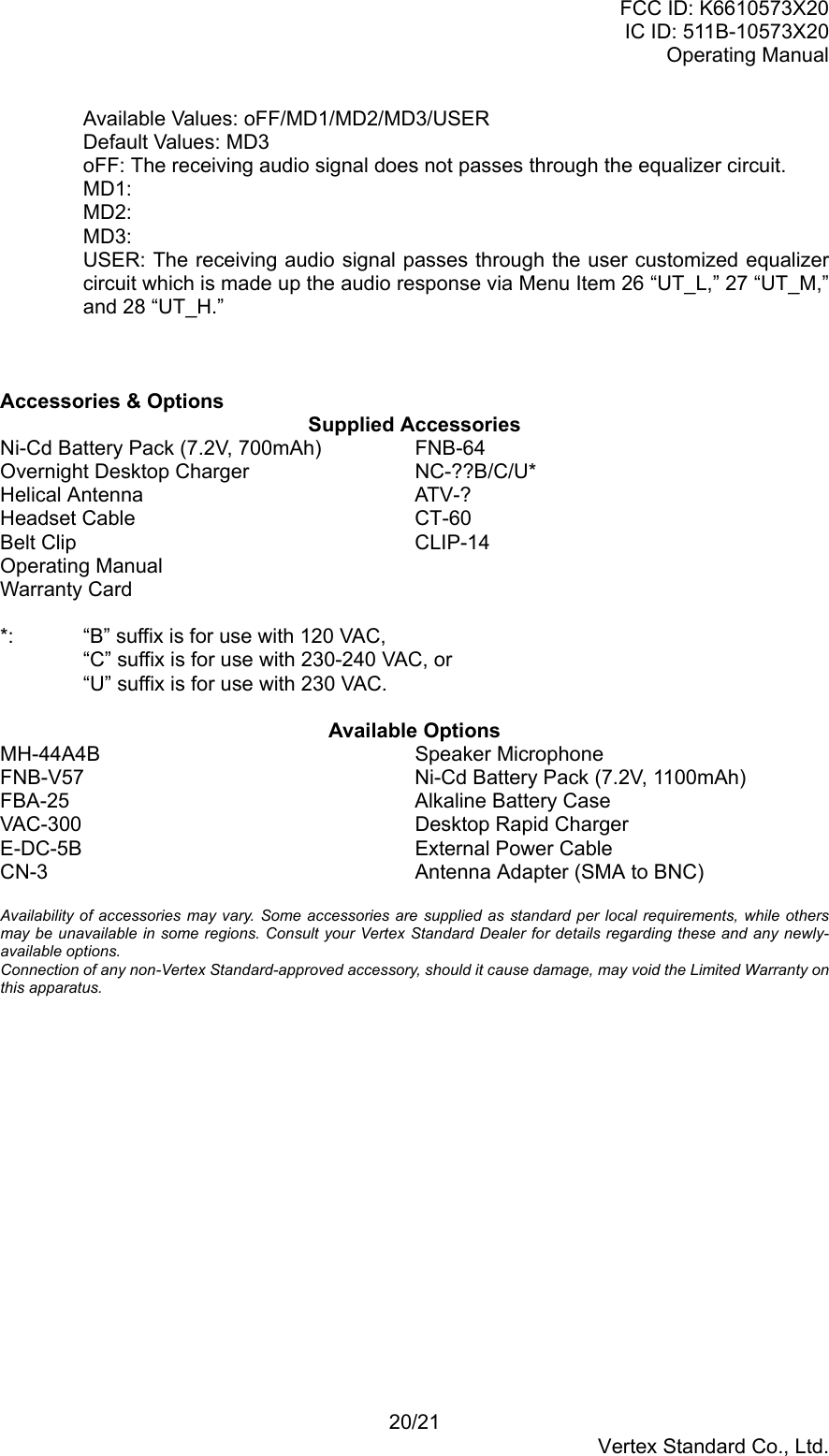
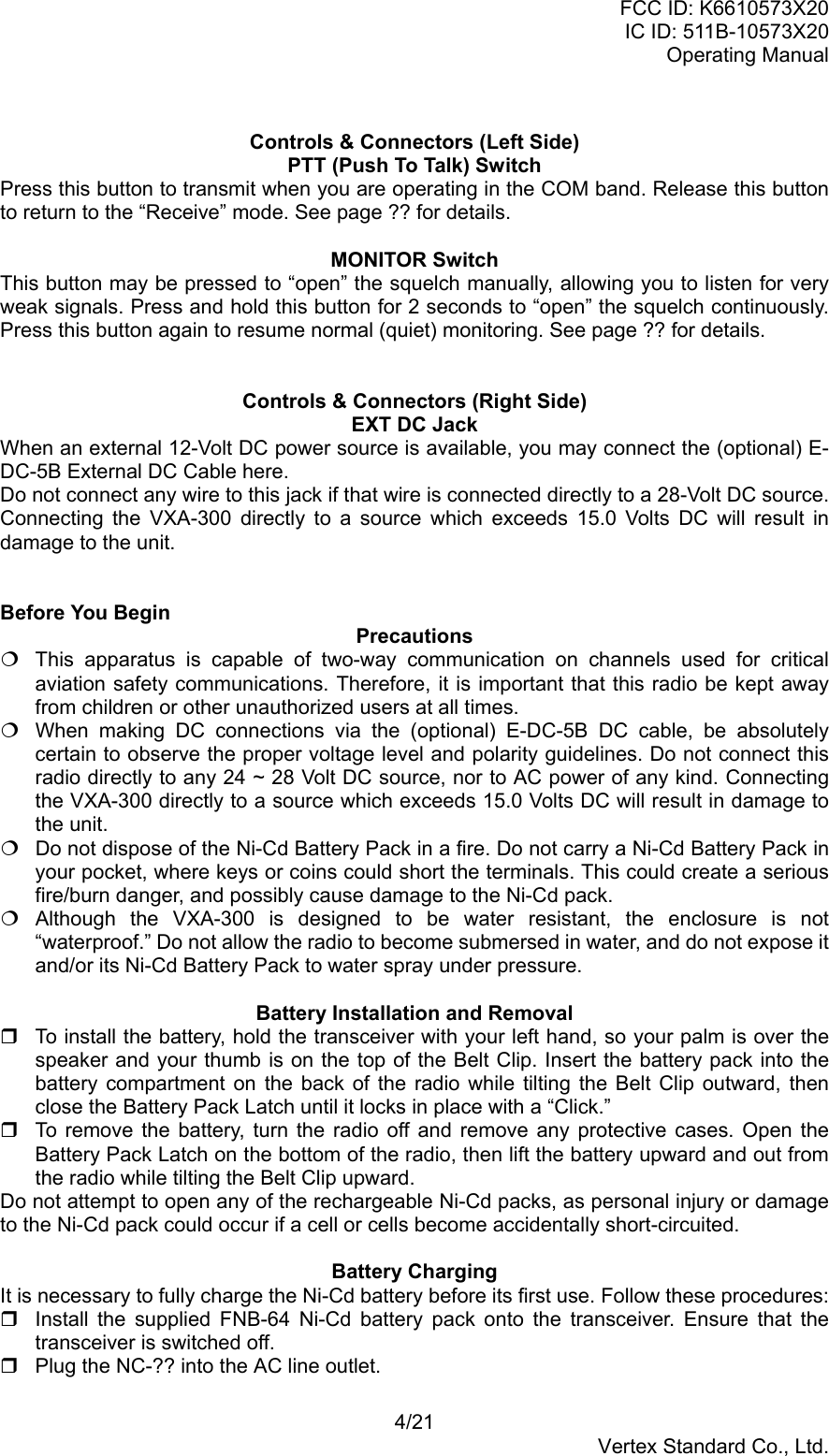
![FCC ID: K6610573X20IC ID: 511B-10573X20Operating Manual3/21Vertex Standard Co., Ltd.Controls & Connectors (Front Panel)BUSY/TX Indicator LampThis lamp glows green when a signal is being received and red when transmitting.LoudspeakerThe internal speaker is located in this position.MicrophoneSpeak across this opening in a normal voice level while pressing the PTT switch, to transmit.LCD (Liquid Crystal Display)The display shows the selected operating conditions as indicated on the next page.KeypadSeveral keys have triple functions.The primary functions are labeled on the key top (activated by simply pressing the keymomentarily).The secondary functions are labeled in yellow above the top edge of the key (activated bypressing the [F] key first, then the indicated key).The third functions are labeled in black above the top edge of the key (activated by pressand holding the indicated key for 2 second).These functions are described in detail on page ??.Battery Pack LatchOpen this latch for battery removal.Primary Function (Press Key) Secondary Function(Press [F] + key)Third Function (Pressand Hold key)[1(DVOR)] Frequency Entry Digit 1 Activates DVOR mode. None[2(TO)] Frequency Entry Digit 2 Activates “TO” VOR mode. None[3(FROM)] Frequency Entry Digit 3 Activates “FROM” VORmode.None[4(CDI)] Frequency Entry Digit 4 Activates Deviation Indicatormode.None[5(TONE)] Frequency Entry Digit 5 Activates Tone Control mode. None[6(TEMP)] Frequency Entry Digit 6 Displays the Battery Voltageand Current Temperatureinside the transceiver’s case.None[7(SPL)] Frequency Entry Digit 7 Activates Split (Duplex)mode.None[8(TIMER)] Frequency Entry Digit 8 Activates the Stop watchtimer.None[9(SKIP)] Frequency Entry Digit 9 Allows Skipping of Channelduring Scan.None[0(SQ)] Frequency Entry Digit 0 Adjusts the Squelch thresholdlevel.None[XFER(LOCK)] Selects Memory Display Type. Activates the Key Lockoutfeature.Selects DVOR DisplayType.[121.5] Selects Emergency Channel (121.5MHz).None None[USER]* Activates the Automatic Noise Limiterduring AM reception.None Switches the ToneCharacter of the ToneControl Circuit.[MW(SPL-W)] None Split-Memory “Write”Command.Memory “Write”Command.[SCAN(DW)] Switches the VFO mode “A” and “B.” Activates the Dual Watchfeature.Activates Scanning.[F] Activates “Secondary” key mode. Cancel the “Secondary” keymode of the [F] key.None*: The primary and third function of the [USER] key may be customized by user via Menumode. See page ?? for details.](https://usermanual.wiki/Yaesu-Musen/10573X20/User-Guide-414018-Page-3.png)
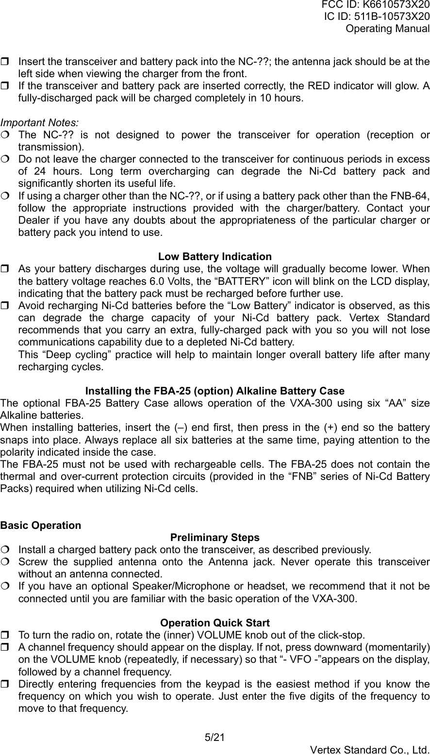
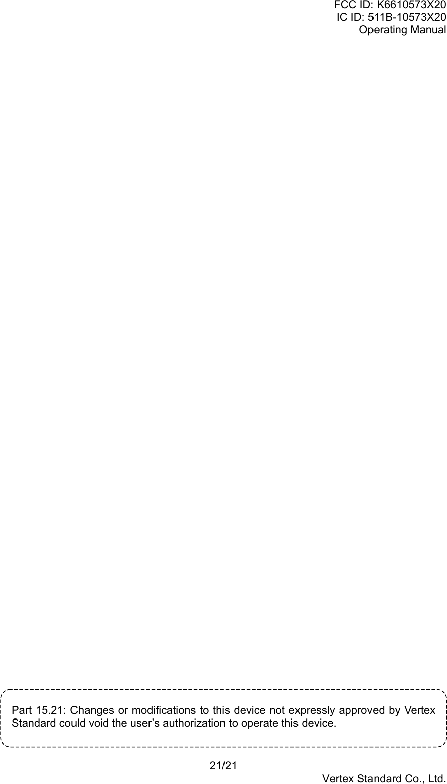
![FCC ID: K6610573X20IC ID: 511B-10573X20Operating Manual6/21Vertex Standard Co., Ltd.For example, to set 134.35 MHz, press [1] Æ [3] Æ [4] Æ [3] Æ [5].To set 118.275 MHz, you do not need to press the final “5” in the frequency:[1] Æ [1] Æ [8] Æ [2] Æ [7]. You may also turn the top panel’s (outer) DIAL selector knob to choose the desiredoperating frequency. The channel frequency will appear on the LCD. Rotate the VOLUME knob to set the volume level. If no signal is present, press and holdthe MONITOR button for 2 seconds; background noise will now be heard, and you mayuse this noise to set the VOLUME knob for the desired audio level. Press the MONITORbutton momentarily to silence the noise and resume normal (quiet) monitoring. To turn the radio off, turn the VOLUME knob fully counter-clockwise into the click stopposition.Squelch Adjustment Press the [F] key momentarily, then press the [0(SQ)] key. This instantly recalls MenuItem 01 “SQL” which is adjusts the threshold level of the squelch circuit. Rotate the DIAL selector knob to set the squelch threshold (0 to 8) so that the receiver isjust silenced. A higher number indicates that a higher signal level is required in order toopen the squelch. Press downward on the VOLUME knob to save your new setting. Press the PTT switch to exit the Menu (“SET”) mode.Accessing the 121.5 MHz Emergency FrequencyThe VXA-300 can quickly access the 121.500 MHz Emergency Frequency. This functioncan be activated even when the keypad lock function (described on page ??) is in use. To access the Emergency Frequency, press the [121.5] key momentarily. To exit the Emergency Frequency, press downward on the VOLUME knob.Transmission To transmit, press and hold the PTT switch. Speak into the microphone area of the frontpanel grille in a normal voice level. To return to the receive mode, release the PTT switch.Advanced OperationTuning MethodsThroughout this manual, you will see references to several different frequency settingmethods. Each will be particularly useful in a particular operating situation, and they aredescribed below: VFO (Variable Frequency Oscillator)The VFO is a “Tuning dial” system which allows you to tune through the NAV, COM or2-m Amateur bands using the DIAL selector, the Keypad, or the scanner. MR (Memory Recall)The MR (Memory Recall) mode of the VXA-300 provides the user with the ability to storeand recall as many as 150 channels in the radio’s main memory bank. These memorychannels may also be labeled by you with an alpha/numeric name of up to 8 charactersin length, to aid in quick identification of the channel. See page ?? for details on creatingalpha/numeric labels. BOOK (Pre-Programmed) MemoriesThe Book memories are pre-programmed, either at the factory or by your Dealer(depending on your country’s requirements), typically including the major COM and NAVband station frequencies used in your area. The Book memories can be changed by theuser. See page ?? for details. WX (Weather Channel) Memories (USA version only)Ten Weather Channels are pre-programmed at the factory. The VXA-300 will](https://usermanual.wiki/Yaesu-Musen/10573X20/User-Guide-414018-Page-6.png)
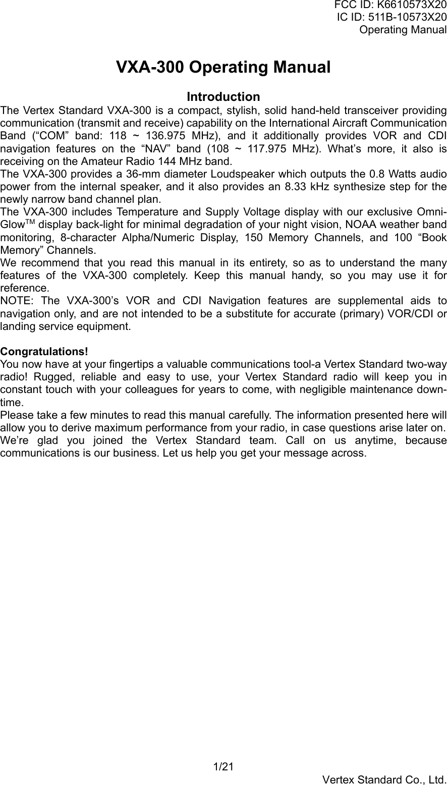
![FCC ID: K6610573X20IC ID: 511B-10573X20Operating Manual7/21Vertex Standard Co., Ltd.automatically scan this special bank when it is selected by the user.Reception of Weather Channel Broadcasts (USA version only)The VXA-300 can receive VHF Weather Channel broadcasts, which may assist your flightplanning. The VXA-300 includes a ten-channel auto-search feature, which simplifies accessto Weather Channels when you are in an unfamiliar location. To receive Weather Channels, press the VOLUME knob (repeatedly, if necessary) toselect the Weather Channel mode. In the Weather Channel mode, “- WX -” will appearon the display. The VXA-300 will now scan quickly through the ten standard Weather Channels, and willstop on the first active station found. If there are two or more weather channels audible in your area, you may select thealternate channel(s) by pressing the PTT switch. Pressing the PTT switch re-initiates thescanning process. If there are no Weather Channels in your area, the scanner will not stop. Press theMONITOR button to stop the scanner. You can also select Weather Channels manually by rotating the DIAL selector knob. To confirm the current Weather Channel frequency, press the [XFER(LOCK)] keymomentarily. The display changes to frequency indication. Press the [XFER(LOCK)] keyagain to return to normal display. To exit the Weather Channel mode, press the VOLUME knob momentarily to return tothe VFO mode.Note 1: In the event of extreme weather disturbances, such as storms and hurricanes, theNOAA (National Oceanic and Atmospheric Administration) sends a weather alertaccompanied by a 1050 Hz tone and subsequent weather report on one of the NOAAweather channels. You may setup the Alert function when receiving the Weather Alert signalvia Menu Item 20 “WXAF,” if desired. See page ?? for details.Note 2: The Weather Channel mode memorizes the last Weather Channel you have used,and will retain this information until the radio is turned off.Monitor KeyWhen listening to a very weak signal from an aircraft or ground station, you may observe thesignal disappearing periodically as the incoming signal strength becomes too weak tooverride the squelch threshold setting.To disable the squelch temporarily, press and hold the MONITOR key for 2 seconds on theleft side of the radio, just below the PTT button. The squelch will remain open and youshould have a better chance of hearing weak signals.To return to normal operation, press the MONITOR key momentarily.ANL (Automatic Noise Limiter) FeatureFor reduction of impulse noise, such as that produced by an engine’s ignition system, theANL feature may prove helpful. The ANL feature is only activated in the AM mode. To activate the ANL feature, press the [USER] key momentarily. The “ANL” icon willappear on the display, and you should observe a reduction in the ignition noise. To turn the ANL feature off, repeat the above step; the “ANL” icon will disappear from thedisplay.Temperature/Battery Voltage DisplayThe VXA-300 can measure the current temperature inside the transceiver’s case andcurrent battery voltage. To display these items, press [F] Æ [6 (TEMP)]. The display will now indicate the current temperature inside the transceiver’s case orcurrent battery voltage.Press the VOLUME knob to switch the display between “current temperature” and](https://usermanual.wiki/Yaesu-Musen/10573X20/User-Guide-414018-Page-7.png)
![FCC ID: K6610573X20IC ID: 511B-10573X20Operating Manual8/21Vertex Standard Co., Ltd.“current battery voltage.” When the VXA-300 display “current temperature,” pressing the [XFER(LOCK)] key toswitch the temperature unit between “Celsius: °C” and “Fahrenheit: °F.” To return to the normal operation, press [F] Æ [6 (TEMP)] again.If the temperature display is incorrectly, it can be re-calibrated via Menu Item 14 “TEMP.”See page ?? for details.LOCK FunctionThe lock function prevents accidental changes to the frequency setting and the keypadcontrols. To activate the lock feature, press [F] Æ [XFER(LOCK)]. In the LOCK mode, the display will show “- LOCK -” when you rotate the DIAL selectorknob, press the VOLUME knob, or touch a key on the keypad. To turn the lock feature off, press [F] Æ [XFER(LOCK)] again. You can still access the 121.500 MHz Emergency Frequency when the LOCK function ison.Simply press the [121.5] key momentarily (this key never locks). Pressing this key alsounlocks the radio.You may choose the lockout combination to your desired. See page ?? for details.Receive Battery Saver SetupAn important feature of the VXA-300 is its Receive Battery Saver, which “puts the radio tosleep” for a time interval, periodically “waking it up” to check for activity. If somebody istalking on the channel, the VXA-300 will remain in the “active” mode, then resume its “sleep”cycles. This feature significantly reduces quiescent battery drain, and you may change theamount of “sleep” time between activity checks using the Menu System: Press the [F] key, then press the VOLUME knob to activate the Menu (“SET”) mode. Rotate the DIAL selector knob to select Menu Item 06 “RSAV.” Press the VOLUNE knob to enable adjustment of this Menu item. Rotate the DIAL selector knob to select the desired “duty cycle” (receive:sleep). Theselections available are 1:1, 1:2, 1:3, 1:4, 1:5, and ABS* or oFF. The default value is 1:1. When you have made your selection, press the VOLUME knob to save the new setting,and then press the PTT key exit to normal operation.*ABS: Automatic Battery Saver, based on activity on the receiver.The setting of 1:5 will promote the greatest conservation of battery capacity, but thereceiver’s response time to incoming calls will be slowed somewhat.Note: This feature does not operate during Scan or Dual Watch.Beep On/OffThe VXA-300’s key/button beeper provides convenient audible feedback whenever a buttonis pressed. Each key and button has a different beep pitch, and each function has a uniquebeep combination.When you are scanning, the beeper will be heard each time the scanner halts on a busychannel. This may be distracting in some environments; if you want to turn the beeper off (orback on again): Press the [F] key, then press the VOLUME knob to activate the Menu (“SET”) mode. Rotate the DIAL selector knob to select Menu Item 05 “BEEP.” Press the VOLUNE knob to enable adjustment of this Menu item. Rotate the DIAL selector knob to select the desired “beeper.” The selections availableare on, DTM, and oFF.on: Sounds a beep corresponding to a musical note.DTM: Sounds a beep corresponding to a DTMF tone.oFF: Disables the key beeper. When you have made your selection, press the VOLUME knob to save the new setting,](https://usermanual.wiki/Yaesu-Musen/10573X20/User-Guide-414018-Page-8.png)
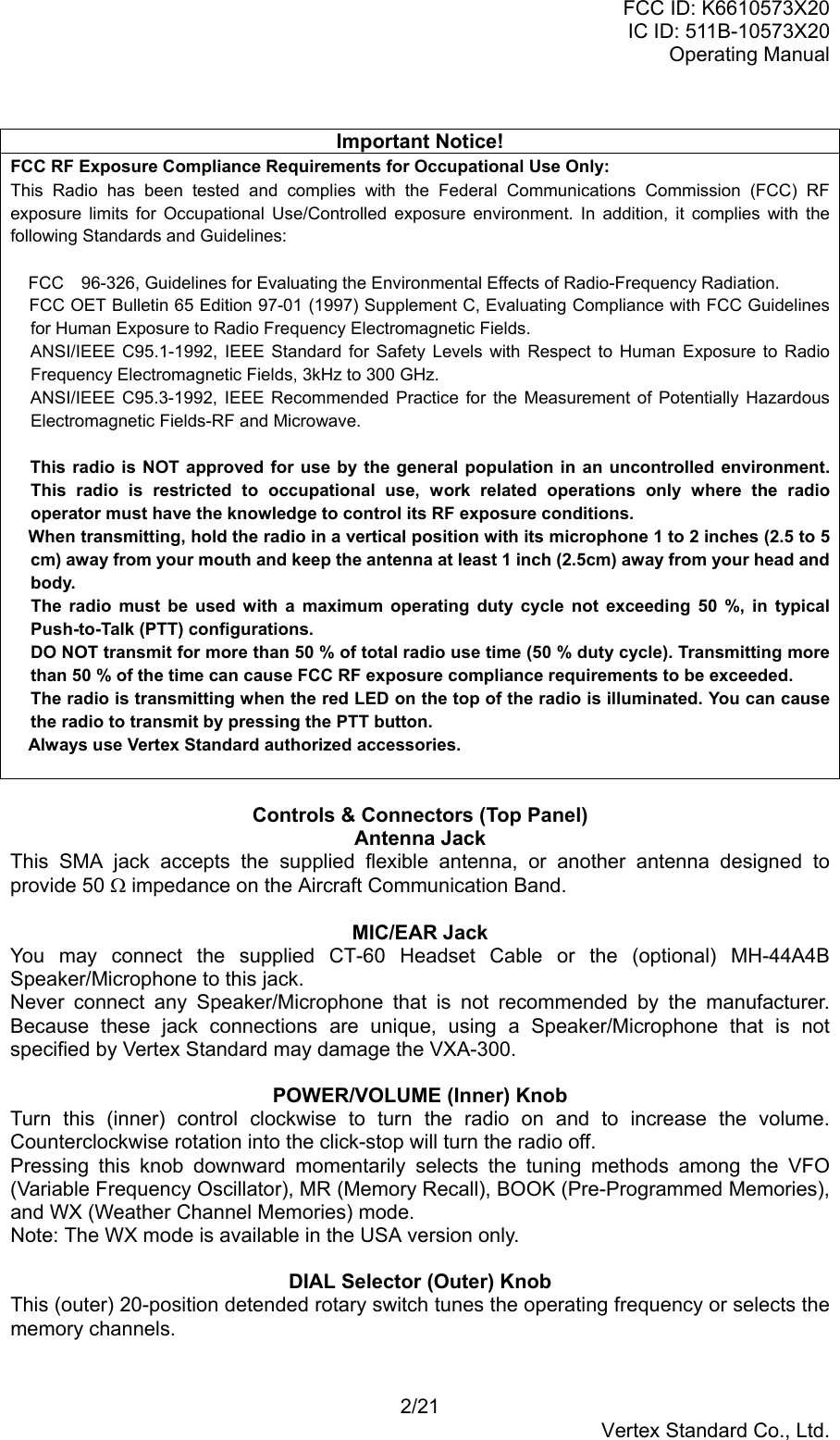
![FCC ID: K6610573X20IC ID: 511B-10573X20Operating Manual9/21Vertex Standard Co., Ltd.and then press the PTT key exit to normal operation.Changing the Channel StepThe VXA-300’s synthesizer provides the option of utilizing channel steps of 8.33/25 kHz perstep for the NAV and COM bands, and 5/10/12.5/15/20/25/50 kHz per step for the 2 mamateur band.The VXA-300 is set up the default channel step to “25 kHz” (NAV, COM and 2 m amateurbands). If you need to change the channel step increments the procedure to do so is veryeasy. Press the [F] key, then press the VOLUME knob to activate the Menu (“SET”) mode. Rotate the DIAL selector knob to select Menu Item 30 “STEP.” Press the VOLUNE knob to enable adjustment of this Menu item. Rotate the DIAL selector knob to select the new channel step size. When you have made your selection, press the VOLUME knob to save the new setting,and then press the PTT key exit to normal operation.Important Note1) When you select the channel step to 8.33 kHz in the NAV and COM band, the channeldisplay differs from actual operating frequency, see below chart. However, the operator(pilot, tower, control, etc) call the frequency by the display .DisplayOperating Frequency 8.33 kHz Step 25 kHz Step1xx.0000 MHz 1xx.005 MHz 1xx.000 MHz1xx.0083 MHz 1xx.010 MHz1xx.0166 MHz 1xx.015 MHz1xx.0250 MHz 1xx.030 MHz 1xx.025 MHz1xx.0333 MHz 1xx.035 MHz1xx.0416 MHz 1xx.040 MHz1xx.0500 MHz 1xx.055 MHz 1xx.050 MHz1xx.0583 MHz 1xx.060 MHz1xx.0666 MHz 1xx.065 MHz1xx.0750 MHz 1xx.085 MHz 1xx.075 MHz1xx.0833 MHz 1xx.085 MHz1xx.0916 MHz 1xx.090 MHzWhen you select the channel step to 8.33 kHz in the NAV and COM band, “” icon willappears in the display.2) The 8.33 kHz step allows to receive function only, transmit function is disabled.3) The adjacent channel selectivity is grown to worse while receiving the signal by the 8.33kHz channel step.Tone ControlThe VXA-300 provides/choose four receiver audio responses to allows most comfortablelistening. Press the [F] key momentarily, then press the [5(TONE)] key. This instantly recalls MenuItem 31 “EQLZ” which is selects the receiver audio responses of radio. Rotate the DIAL selector knob to select desired receiver audio response. Availableselections are:oFF: The receiving audio signal does not passes through the equalizer circuit.MD1:MD2:MD3:USER: The receiving audio signal passes through the user customized equalizer circuitwhich is made up the audio response via Menu Item 26 “UT_L,” 27 “UT_M,” and28 “UT_H.” When you have made your selection, press the VOLUME knob to save the new setting,and then press the PTT key exit to normal operation.](https://usermanual.wiki/Yaesu-Musen/10573X20/User-Guide-414018-Page-9.png)
![FCC ID: K6610573X20IC ID: 511B-10573X20Operating Manual10/21Vertex Standard Co., Ltd.VOX OperationThe VOX system provides automatic transmit/receive switching based on voice input to themicrophone. With the VOX system enabled, you do not need to press the PTT key in orderto transmit, and it is not necessary to use a VOX headset in order to utilize VOX operation. Press the [F] key, then press the VOLUME knob to activate the Menu (“SET”) mode. Rotate the DIAL selector knob to select Menu Item 21 “VOX.” Press the VOLUNE knob to enable adjustment of this Menu item. Rotate the DIAL selector knob to select “on” (to enable the VOX system). When you have made your selection, press the VOLUME knob to save the new setting,and then press the PTT key exit to normal operation. Without pressing the PTT key, speak into the microphone in a normal voice level. Whenyou start speaking, the transmitter should be activated automatically. When you finishspeaking, the transceiver should return to the receive mode (after a short delay). To cancel VOX and return to PTT operation, just repeat the above procedures, selecting“oFF” in step 4 above.When the VOX system is activated, the “V” icon will appear on the display.The VXA-300 provides for adjustment of the VOX Gain via the Menu, to prevent accidentaltransmitter activation in a noisy environment. To set a VOX Gain: Press the [F] key, then press the VOLUME knob to activate the Menu (“SET”) mode. Rotate the DIAL selector knob to select Menu Item 23 “VSNS.” Press the VOLUNE knob to enable adjustment of this Menu item. While speaking into the microphone, rotate the DIAL selector knob to the point wherethe transmitter is quickly activated by your voice, without causing background noise toactivate the transmitter. When you have selected the optimum setting, press the VOLUME knob to save the newsetting, and then press the PTT key exit to normal operation.The VXA-300 also provides for adjustment of the “Hang-Time” of the VOX system (thetransmit-receive delay after the cessation of speech) via the Menu. The default delay is 0.1second. To set a different delay time: Press the [F] key, then press the VOLUME knob to activate the Menu (“SET”) mode. Rotate the DIAL selector knob to select Menu Item 22 “VDLY.” Press the VOLUNE knob to enable adjustment of this Menu item. Rotate the DIAL selector knob to select the delay time among “05,” “10,” “15,” and “20”(x0.1 sec). When you have made your selection, press the VOLUME knob to save the new setting,and then press the PTT key exit to normal operation.PA OperationThe PA mode allows the VXA-300 to be used as a Public Address System when an optionalMH-44A4B Microphone is connected.Note: If you wish to operate the PA mode, change the [USER] key assignment to the “PA”item, at first. See page ?? for detail. Press (or Press and hold) the [USER] key to activate the PA mode. Press the microphone’s PTT switch to speak through the VXA-300 internal speaker.The “Course Deviation Needle” defect accordance with the voice level. Rotate theVOLUME knob to control the AF output level. To exit the PA mode, press (or Press and hold) the [USER] key again.](https://usermanual.wiki/Yaesu-Musen/10573X20/User-Guide-414018-Page-10.png)
![FCC ID: K6610573X20IC ID: 511B-10573X20Operating Manual11/21Vertex Standard Co., Ltd.Memory OperationThe VXA-300 provides 150 user-programmable “Main” memories, labeled “CH-001” through“CH-150,” and up to 100 pre-programmed memories, designated “Book” Memories. The“BOOK” icon appears when “Book” Memory Mode is activated.The Main memories and “Book” Memories can be assigned alpha-numeric names of up toeight characters.Memory System OperationThe VXA-300’s Main Memory system allows the user to store, label, and recall channelfrequencies which you may want to use frequently. You may store VFO frequencies, BookMemory frequencies, and/or Weather Channel frequencies (USA version only) into the MainMemory system.Memory Storage Select the desired frequency in the VFO mode, or recall the Book Memory channel orWeather channel to be stored in the Main Memory. Press and hold the [MW(SPL-W)] key for 2 seconds. The display will indicate “CH-XXX”and a channel number will blink on the LCD. Within five seconds of pressing the [MW(SPL-W)] key, rotate the DIAL selector knob toselect the desired memory channel number for storage.In order to prevent writing over memory channels, a under bar will appear under thehyphen (located between “CH” and the channel number) to indicate a vacant memorychannel. Now press and hold in the [MW(SPL-W)] key for 2 seconds; you will now see “A - - - - - --” on the LCD. To attach an alpha/numeric name (label) to the memory, proceed to thenext step; otherwise press and hold [MW(SPL.W)] for 2 seconds to save the entry andexit. To label a memory with an alpha/numeric name, the next step is to use the DIAL selectorknob to select any of the 48 available characters (including letters, numbers, and specialsymbols). When the desired first character appears, press the VOLUME knobmomentarily to move on to the next character. Select succeeding characters in the same manner, pressing the VOLUME knobmomentarily after each selection. After entering the entire name (eight characters maximum), press the [MW(SPL-W)] keyfor 2 seconds to save all data for the channel and exit.Note: If you have stored a Weather Channel, the “WX-001 ~ WX-010” labels utilize thealphanumeric memory, and other labels may not be stored.Recalling the Memories Press the VOLUME knob, repeatedly if necessary, until “- MR -” (Memory Recall)appears on the display. In the MR mode, you will see “CH-” and the previously selectedchannel number appearing on the LCD. Rotate the DIAL selector knob to select the desired memory channel. You may change the title structure of the Memory display type among:1. Channel Indication (sequential Channel Number, e.g. CH-001, CH-002, etc.);2. Frequency Indication (e.g. 122.500); or3. Alphanumeric Label (e.g. LAX FSS). To change the Memory display title, press the [XFER(LOCK)] key repeatedly, ifnecessary, until you get the desired display title structure. To exit the Memory mode, press the DIAL selector knob three times to return to the VFOmode.Note: In either the “MR” or the “Book” Memory mode, an easy way to recall memories is tokey in the memory channel number, then press the [SCAN(DW)] key. For example, to recallmemory channel #14, press [1] Æ [4] Æ [SCAN(DW)].](https://usermanual.wiki/Yaesu-Musen/10573X20/User-Guide-414018-Page-11.png)
![FCC ID: K6610573X20IC ID: 511B-10573X20Operating Manual12/21Vertex Standard Co., Ltd.Scanning OperationThe VXA-300 allows you to scan automatically in the VFO*1, Main Memory, “Book” Memory,or Weather Channel*2 modes. It pauses on signals encountered, so you can talk to thestation(s) on that frequency, if you like.*1: In the VFO mode, the automatic scanner is only available in the COM band (118.000 -136.975 MHz); when the scanner reaches the uppermost frequency in the COM band, itwill revert to the bottom end of the COM band and repeat the scanning process until youcancel the scanning process.*2: USA version only.If you wish to scan in the NAV band (108.000 - 117.975 MHz), you can do so manually, asdescribed at the right.Scanning operation is basically the same in each of the above modes. Press and hold the [SCAN(DW)] key for 2 seconds to start the automatic scannerupward (toward a higher frequency or a higher channel number). When the scanner encounters a signal, scanning pauses and the radio remains on thatchannel until one second after the signal disappears, after which scanning will resume. While the scanner remains paused on a frequency, the decimal point of the frequencydisplay blinks. The display will be illuminated unless the Scan Lamp Feature is turnedoff. To change the scan direction, turn the DIAL selector knob one click in the oppositedirection. To stop the automatic scanner, press the PTT switch or the VOLUME knob momentarily.You may also just press the [SCAN(DW)] key.The VXA-300’s automatic scanner is not operational in the NAV band (108.000 - 117.975MHz), because the NAV stations (ILS, etc.) transmit constantly (thereby causing the scannerto stop repeatedly). However, you can scan manually in the NAV band, per the followingprocedure: Press and hold the [SCAN(DW)] key to start the manual scanner. Scanning will continueas long as the key is depressed. Release the [SCAN (DW)] key to stop the manual scanner immediately.Note: When scanning upward in frequency, when the frequency reaches the COM Band(118.000 - 136.975 MHz) via manual scanning, The VXA-300 will switch to the automaticscanner mode.Channel-Skip ScanningContinuous-carrier stations like ATIS (Automatic Terminal Information Service) or WeatherBroadcast stations inhibit scanner operation. Since these stations are always active, thescanner will be halted repeatedly on their channels. Such channels can be set to be“skipped” during Memory scanning (MR, Book or WX modes), if you like, so as not tointerfere with automatic channel scanning: Recall the Memory Channel to be skipped during scanning. Press [F] Æ [9(SKIP)]. The “SKIP” icon will appear at the upper right of the channelnumber, indicating that the channel is to be ignored during scanning. You can also designate a channel to be skipped while scanning. When the receiver ishalted on a channel that you wish to skip, press and hold the [SCAN(DW)] key for 2seconds (the “SKIP” icon will appear next to the channel to be skipped). Later, to re-enable the memory channel for scanning, repeat the first two steps. The“SKIP” icon will disappear by the channel you have just re-enabled.Note: A memory set to be “skipped” is still accessible for manual memory selection using theDIAL selector knob.](https://usermanual.wiki/Yaesu-Musen/10573X20/User-Guide-414018-Page-12.png)
![FCC ID: K6610573X20IC ID: 511B-10573X20Operating Manual13/21Vertex Standard Co., Ltd.Dual Watch OperationThe Dual Watch feature automatically checks for activity on a “priority” channel* while youare operating on another channel. During Dual Watch operation, the current channel and thePriority channel will each be polled for a 500 ms interval, as the VXA-300 looks for activityon each channel. To start Dual Watch, press [F] Æ [SCAN(DW)]. The “DW” icon will appear on the display. While receiving on the “current” channel (not the Priority channel), you may push thePTT switch at any time to transmit on that channel. When a signal is received on the Priority channel, operation immediately shifts to thePriority channel, the “DW” icon will blink, and the display will become illuminated. While receiving on the priority channel, if you momentarily press the PTT switch, DualWatch will be disabled. You may then transmit on the Priority Channel. To stop Dual Watch, press [F] Æ [SCAN(DW)]. If you wish, you may use both the Dual Watch and Scan features simultaneously. To dothis, start the Dual Watch first, then start the Scanner.*: The “priority” Channel is defined as the last-used Memory Channel (when using the VFOmode) or Memory Channel 1 (when using the Main Memory or Book Memory modes).Priority Dual Watch OperationSimilar to Dual Watch operation (described on previous page), Priority Dual Watch is anenhanced version which includes the following additional features: The receiving time interval (ratio) between the current channel and the Priority channelmay be customized via the Menu Item 09 “PRTM.” See page ?? for details. Irrespective of which channel is currently being received, when the PTT button ispushed transmission will always occur on the Priority channel.Before initiating Priority Dual Watch, Menu Item 10 “DWMD” must be set to the “PRI:Priority” mode (instead of “DW: Dual Watch”). See page ?? for details. To start Priority Dual Watch, press [F] Æ [SCAN(DW)]. The “DW” icon will appear on thedisplay. While receiving on the “current” (non-Priority) channel, pressing the PTT button oncecauses the radio to switch to the Priority channel and cancels Dual Watch. Press thePTT button again to transmit on the Priority channel. When a signal is received on the Priority channel, reception immediately shifts to thePriority channel, the “DW” icon will blink, and the display will become illuminated unlessthe Scan Lamp Feature is turned off.While receiving on the priority channel, if you momentarily press the PTT switch, PriorityDual Watch will be disabled. You may then transmit on the Priority Channel. To stop Priority Dual Watch, press [F] Æ [SCAN(DW)].VOR NavigationTo Select the DVOR Mode When entering the NAV band (108.000 - 117.975 MHz), the VXA-300 selects the DVORmode automatically. The “Course Indicator” field will appear at the upper left corner onthe display, and the “TO” or “FROM” indicator will appear below the “Course Indicator”field on the display.Note: The “Course Indicator” indicates “- - -” when either your aircraft is too far awayfrom the VOR station or the frequency is not correctly set to that of the VOR station.Conversely, the “Course Indicator” will indicate “Loc” when a localizer signal is beingreceived. The “TO” or “FROM” flag indicators indicate whether the VOR navigation information is](https://usermanual.wiki/Yaesu-Musen/10573X20/User-Guide-414018-Page-13.png)
![FCC ID: K6610573X20IC ID: 511B-10573X20Operating Manual14/21Vertex Standard Co., Ltd.based on a course leading to the VOR station or leading away from the VOR station. To change the flag from “TO” to “FROM” or vice versa, press the [F] Æ [3(FROM)] or[2(TO)] key, respectively. The small “Course Indicator” and “TO/FROM” flag indicators may be toggled to thelarger “Frequency” portion of the display. To do this, press and hold in the[XFER(LOCK)] key for 2 seconds to toggle to the larger display area. Press the[XFER(LOCK)] key momentarily again to return to the smaller displays.Flying to a VOR StationThe VXA-300 can indicate the deviation from the direct course to a VOR station. Select a VOR station on your aeronautical chart and turn the DIAL selector knob (orenter the frequency directly with the keypad) to the frequency of the VOR station. To indicate the deviation between your current flight path and the desired course, press[F] Æ [4(CDI)] to change to the CDI (Course Deviation Indicator) mode. The “CourseDeviation Arrow” will appear above the frequency field on the display when your aircraftis off the direct course to the VOR station. When your aircraft is off course to the right, the Course Deviation Arrow display willshow bars to the left side of the diamond (“||”). When your aircraft is off course to theleft, the Course Deviation Arrow display will show bars to the right side of the diamond(“||”). Correct your course until no bars appear on either side of the CDI “Diamond”(only “”) will be visible when the heading is correct). To return to the DVOR mode, press [F] Æ [1(DVOR)].Entering a Desired CourseThe VXA-300 can also be configured to indicate the deviation from the desired course, notonly the deviation from the path to the VOR station. Set the frequency to the desired VOR station. To change the “TO” or “FROM” flag to “TO,” if it is not in that mode already. Press [F] Æ [4(CDI)] key to change to the CDI mode. Set the desired course to the VOR station using the DIAL selector knob or keypad (threedigits input; e.g. 47°, press [0] Æ [4] Æ [7]).Note 1: The (“||”) or (“||”) indication will appear on the display when your aircraft is offthe desired course.Note 2: When your heading is correct, the ABCS function may be more useful than thecourse input option. The Course Deviation Arrow points to the right when your aircraft is off course to the left,and it points to the left when your aircraft is off course to the right.Note 1: To get back on course, fly right more than the number of degrees indicated bythe Course Deviation Arrow.Note 2: If the overflow indicator “ appears on the right side, select a heading plus 10degrees to the desired course; if the overflow indicator “ appears on the left side,select a heading minus 10 degrees.ABCS ModeIn the CDI mode, the Auto Bearing Center System (ABCS) adds or subtracts the number ofdegrees indicated by the CDI from the Omni Bearing Selector (OBS).Position Cross-checking Select two VOR stations on your aeronautical chart. Set the frequency of one of the VOR stations in the DVOR mode. The course indicatorwill show the course deviation from the VOR radial. Note the radial you currently are on. Now set the frequency of the other VOR station in the DVOR mode. Note the radial fromthe station you are on.](https://usermanual.wiki/Yaesu-Musen/10573X20/User-Guide-414018-Page-14.png)
![FCC ID: K6610573X20IC ID: 511B-10573X20Operating Manual15/21Vertex Standard Co., Ltd. Extend the radials from each VOR station on the chart. Your aircraft is located at thepoint where the lines intersect.Split OperationThe split operation feature allows you to transmit a call to a Flight Service Station using theCOM band frequencies, while receiving a VOR station (in the NAV band). VOR stationsequipped with this capability typically are shown, on navigation charts, with the voice callingfrequency in parenthesis above the navigation frequency.Programming a Transmit Frequency Press the VOLUME knob, repeatedly if necessary, to select the VFO mode. Set a NAV band (108.000 - 117.975 MHz) frequency using the DIAL selector knob orkeypad. Press [F] Æ [MW(SPL-W)]. The “SPL” icon will blink, and the transmit frequency willappear on the display. Now set your radio’s transmit frequency, where the Flight Service Station will belistening for calls, using the DIAL selector knob or keypad. r Press and hold in the [MW(SPL-W)] key for 2 seconds to save the transmitfrequency and return to the NAV band frequency.Note: You have now stored the separate transmit frequency, but you have not yet activatedthe split-frequency function; go on to the next section.Operating in the Split Mode It is assumed that you have already set the desired VOR station’s frequencies (in theNAV band) per the above instructions. Press [F] Æ [7(SPL)] to turn on the “Split” function. The “SPL” icon will appear on thedisplay. Press and hold in the PTT switch to transmit on the split transmit frequency. Release the PTT switch to return to the receive mode. To disable the “Split” function, press [F] Æ [7(SPL)] again.Note: A split frequency can be programmed into each memory channel independently. Set atransmit frequency before programming the memory channel, if desired. The split functionon/off setting can also be programmed into a memory channel.Field Programming ModeThe VXA-300’s Book Memories also allow the user to store, label, and recall channelfrequencies which you may want to use frequently while the VXA-300 is in the FieldProgramming mode.Memory Storage into the Book Memory Press and hold the PTT and VOLUME knob while turning the radio on, to activate theField Programming Mode. Select the desired frequency to be stored in the Book Memory. Press and hold the [MW(SPL-W)] key for 2 seconds. The display will indicate “-BOOK –“ and a channel number will blink on the LCD. Within five seconds of pressing the [MW(SPL-W)] key, rotate the DIAL selector knob toselect the desired memory channel number for storage. Now press and hold in the [MW(SPL-W)] key for 2 seconds; you will now see “A - -- - - - -” on the LCD. To attach an alpha/numeric name (label) to the memory, proceed tothe next step; otherwise press and hold the [MW(SPL-W)] key for 2 seconds to save theentry and exit. To label a memory with an alpha/numeric name, the next step is to use the DIAL selectorknob to select any of the 48 available characters (including letters, numbers, and special](https://usermanual.wiki/Yaesu-Musen/10573X20/User-Guide-414018-Page-15.png)
![FCC ID: K6610573X20IC ID: 511B-10573X20Operating Manual16/21Vertex Standard Co., Ltd.symbols). When the desired first character appears, press down on the VOLUME knobmomentarily to move on to the next character. Select succeeding characters in the same manner, pressing down on the VOLUMEknob momentarily after each selection. After entering the entire name (eight characters maximum), press the [MW(SPL-W)] keyfor 2 seconds to save all data for the channel. Repeat this procedure to store additional frequencies into the Book Memory section, asdesired. Turn the radio off, then turn the radio back on again to begin normal operation.Menu (“Set”) ModeThe Menu system allows certain aspects of your radio’s configuration to be customized foryour personal operating convenience. We do not recommend that any of the default settingsbe changed, however, until you are thoroughly familiar with the operation of the VXA-300.1. Press the [F] key, then press the VOLUME knob to activate the Menu (“SET”) mode.2. Rotate the DIAL selector knob to select the Menu item (feature) you wish to view and/ormodify.3. Once you have selected the desired Menu Item, press the VOLUME knob once toenable adjustment of this Menu item. The current setting value will be blinking.4. Rotate the DIAL selector knob to change the setting of the item (“on” to “oFF,” etc.).5. Press the VOLUME knob to save your new setting.6. If you need to change more than one Menu item, repeat steps 2 - 5.7. Press the PTT switch to exit the Menu (“SET”) mode.MENU ListingA listing of the Menu items available via the SET mode may be found below.01 [SQL]Function: Squelch Level Setting.Available Values: 0 ~ 8Default Setting: 6Select a setting for this Menu item which just silences the receiver when no signalis present. Use the lowest setting which will keep the receiver quiet betweenincoming transmissions.02 [MCLR]Function: Memory Channel Clear (“MR” memory only).To clear a Memory channel: Select the Menu Item MCLR. Press the VOLUME knob, then rotate the DIAL selector knob to recall thememory channel to be erased. Press the VOLUME knob to clear the Memory channel (Memory channelnumber will return to “001”).Important Notice: An “erased” channel cannot be restored, and “CH-001” cannotbe erased, as it is used for “Priority Channel” operation.03 [RESM]Function: Scan-Resume Mode Setting.Available Values: 5S/CARDefault Setting: 5S“5S” (5-Second Pause) mode: the scanner will halt for five seconds only, afterwhich scanning will resume (whether or not the other station is still transmitting).“CAR” (Carrier Drop) mode: the scanner will remain halted for as long as there is acarrier present on the channel; after the carrier drops at the end of the otherstation’s transmission, the scanning will resume.04 [SCNL]](https://usermanual.wiki/Yaesu-Musen/10573X20/User-Guide-414018-Page-16.png)
![FCC ID: K6610573X20IC ID: 511B-10573X20Operating Manual17/21Vertex Standard Co., Ltd.Function: Scan Lamp On/Off (while paused).Available Values: on/oFFDefault Setting: onIf you set this function to “on,” the lamp will be illuminated whenever the scannerpauses. The lamp will go off automatically when scanning resumes.05 [BEEP]Function: Keypad Beeper On/Off.Available Values: on/DTM/oFFDefault Setting: onon: Sounds a beep corresponding to a musical note.DTM: Sounds a beep corresponding to a DTMF tone.off: Disables the key beeper.If you do a lot of scanning, you may wish to set this Menu item to “oFF,” as theBeeper will be heard each time the scanner pauses.06 [RSAV]Function: Selects the Receive-mode Battery Saver “sleep” ratio.Available Values: 1:1 ~ 1:5/oFF/ABS*Default Setting: ABSThe setting of 1:5 will promote the greatest conservation of battery capacity, but thereceiver’s response time to incoming calls will be slowed somewhat.*ABS: Automatic Battery Saver, based on activity on the receiver.Note: This feature does not operate during Scan or Dual Watch.07 [LAMP]Function: Display and Keypad Illumination Mode.Available Values: KEY/oFF/CNTDefault Setting: KEY“KEY” mode: The illumination lamp will be activated for 5 seconds when any frontpanel key, VOLUME knob, and DIAL knob is operated.“oFF” mode: Disables the illumination lamp.“CNT” mode: Illuminates the Display/Keypad continuously.08 [SFT]Function: CPU Clock Shift.Available Values: on/oFFDefault Setting: oFFThis function is only used to move a spurious response “birdie” should it fall on adesired frequency. Consult your Vertex Standard dealer for details regarding thisfunction.09 [PRTM]Function: Selects the Priority Checking Time.Available Values: 05/10/15/20/25/30 (x0.1 sec)Default Setting: 20 (2 seconds)This Menu item allows you to define how often the Priority Channel will be checkedfor activity.Note: The Dual Watch Polling time is 500 mS (fixed).10 [DWMD]Function: Selects the Dual Watch/Priority Function.Available Values: DW/PRIDefault Setting: DW“DW” mode: The VXA-300 will activate the Dual Watch feature when you press [F]Æ [SCAN(DW)].“PRI” mode: The VXA-300 will activate the Priority feature when you press [F] Æ[SCAN(DW)].11 [POBP]Function: Select the Power on Beep.](https://usermanual.wiki/Yaesu-Musen/10573X20/User-Guide-414018-Page-17.png)
![FCC ID: K6610573X20IC ID: 511B-10573X20Operating Manual18/21Vertex Standard Co., Ltd.Available Values: MD1/MD2/MD3/oFFDefault Setting: MD112 [IMIC]Function: Internal Microphone On/Off.Available Values: on/oFFDefault Setting: oFFThis controls the status of the radio’s internal microphone when an externalmicrophone (such as the MH-44A4B Speaker Microphone or an aviation headsetconnected via the CT-60 Headset Cable) is in use. In most applications, set 12[IMIC] to “oFF” for proper operation (this disables the internal microphone). Theinternal microphone will still function normally when the external microphone isdisconnected.13 [EMRG]Function: Emergency channel On/Off.Available Values: on/oFFDefault Setting: onThis controls the operation of the Emergency [121.5] key. When set to “oFF,” thiskey will not function. You can still use the frequency 121.5 MHz either by entering iton the keypad in the VFO mode, or by recalling it on a previously-stored memorychannel.14 [TEMP]Function: Correcting the thermometer setting.Available Values: -127 ~ +127 (x0.1 °C)Default Setting: 000 (ºC)This allows you to calibrate the internal thermometer with a known-to be-accuratesource.15 [UNIT]Function: Selects the measurement units for the temperature sensor.Available Values: °F/°CDefault Setting: °F16 [TOT]Function: Setting of the Time-Out Timer countdown time.Available Values: 1/3/5/oFF (minute)Default Setting: oFFThe Time-Out Timer shuts off the transceiver after continuous transmissionexceeds the programmed time.17 [DIMM]Function: Setting of the display brightness level.Available Values: LV1 ~ LV4Default Setting:LV318 [KEY1]Function: Programming the primary (momentary press mode) [USER] keyassignment.Available Values: no/ANL/PA/EQDefault Setting: ANLSee page ?? for details.19 [KEY2]Function: Programming the third (press and hold mode) [USER] key assignment.Available Values: no/ANL/PA/EQDefault Setting: EQSee page ?? for details.20 [WXAF]Function: Selects the Alert functions when receiving the Weather Alert Signal onthe WX channel.](https://usermanual.wiki/Yaesu-Musen/10573X20/User-Guide-414018-Page-18.png)
![FCC ID: K6610573X20IC ID: 511B-10573X20Operating Manual19/21Vertex Standard Co., Ltd.Available Values: BP/LED/B+L/oFFDefault Setting: oFFBP: Sounds a loud beep when receiving the Weather Alert Signal.LED: Flashes the BUSY/TX indicator when receiving the Weather Alert Signal.B+L: Sounds a loud beep and flashes the BUSY/TX indicator when receiving theWeather Alert Signal.oFF: Disable the Alert function.21 [VOX]Function: Enables/disables the VOX operation.Available Values: on/oFFDefault Setting: oFF22 [VDLY]Function: Selects the VOX delay (“hang”) time.Available Values: 05/10/15/20 (x0.1 sec)Default Setting: 10 (x0.1 sec)23 [VSNS]Function: Sets the VOX sensitivity.Available Values: 0 ~ 255Default Setting: 12724 [HPLV]Function: Sets the Headphone audio level.Available Values: 0 ~ 7Default Setting: 625 [PASP]Function: Enables/disables the External Speaker while operating on the PAfunction.Available Values: on/oFFDefault Setting: oFF26 [UT_L]Function: Selects the low-frequency audio response for the user customized tonecontrol of the audio amplifier in the receiver.Available Values: +/–/oFFDefault Setting: oFF27 [UT_M]Function: Selects the audio response .Available Values: +/–/oFFDefault Setting: oFF28 [UT_H]Function: Selects the audio response .Available Values: +/–/oFFDefault Setting: oFF29 [LOCK]Function: Selects the control locking lockout combination.Available Values: K/KD/P/PD/PK/PKD/DDefault Setting: KDK: Keypad (includes pressing the VOLUME knob function), D: DIAL knob, P: PTTswitch30 [STEP]Function: Selects the synthesizer step on the Air band.Available Values: 25 kHz/8 kHzDefault Values: 25 kHz31 [EQLZ]Function: Selects the equalizer (tone control) circuit of the audio amplifier in thereceiver.](https://usermanual.wiki/Yaesu-Musen/10573X20/User-Guide-414018-Page-19.png)