Yaesu Musen 10613030 MOBILE FM TRANSCEIVER User Manual p65
Yaesu Musen Co., Ltd. MOBILE FM TRANSCEIVER p65
UserManual.wiki
>
Yaesu Musen
>
10613030 User Manual
>
USERS MANUAL 1
Contents
1.
USERS MANUAL 1
2.
USERS MANUAL 2
USERS MANUAL 1
Navigation menu
Upload a User Manual
Namespaces
Wiki Guide
HTML
PDF
Info
Views
User Manual
Discussion / Help
Navigation

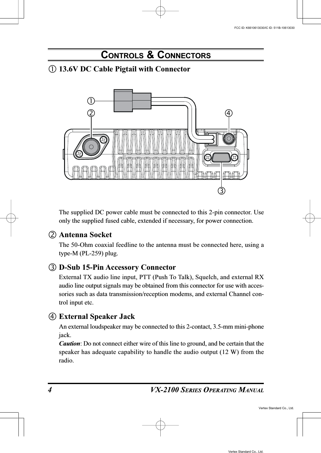
![VX-2100 SERIES OPERATING MANUAL2CONTROLS & CONNECTORSFront PanelImportant! - All buttons located on the Front Panel are Programmable Function (PF)Buttons, configured according to your network requirements and programmed byyour VERTEX STANDARD dealer. The instructions below discribe a typically-con-figured radio.VOL/PWR KnobTurn this control clockwise to turn the radio on and to increase the volume. Turnit counterclockwise into the click-stop to turn the radio off.Microphone JackConnect the microphone plug to this jack.[P1] - [P4] Buttons (Programmable Function Buttons)These buttons can be set up for special applications, such as High/Low powerselection, Monitor, Talk-Around, etc., as determined by your network require-ments and programmed by your VERTEX STANDARD dealer.[]/[] Buttons (Programmable Function Buttons)In the factory default, pressing either button changes the current channel (anddisplayed channel number or name). Holding in either button for more than 1.5second causes the radio to begin stepping (repeatedly) upward or downwardthrough the channels. Vertex Standard Co., Ltd.FCC ID: K6610613030/IC ID: 511B-10613030Vertex Standard Co., Ltd.](https://usermanual.wiki/Yaesu-Musen/10613030.USERS-MANUAL-1/User-Guide-741160-Page-4.png)
![VX-2100 SERIES OPERATING MANUAL 5BASIC OPERATION OF THE TRANSCEIVERImportant! - Before turning on the radio the first time, confirm that the power con-nections have been made correctly and that a proper antenna is connected to theantenna jack.Switching Power ON/OFFTurn the VOL/PWR knob turn on the radio. The display will become illumi-nated.Press the []/[] button to choose the desired operating channel. A channelname will appear on the display.Setting the VolumeTurn the VOL knob clockwise to increase the volume, and counterclockwise todecrease it.TransmittingTo transmit, monitor the channel and make sure it is clear.THIS IS AN FCC REQUIRMENT!Press the PF button which is programmed to the Monitor feature to listen forchannel activity.When receiving a call, transmit only after the incoming call ends. The radiocannot receive a call and transmit simultaneously.Press the PTT switch.If the channel is clear, the TX/BUSY indicator will glow red. The radio is nowtransmitting. While holding in the PTT switch, speak across the face of the micro-phone in a clear and normal voice. For best transmission, hold the microphoneabout 1-1/2 to 2 inches away from your mouth. Release the PTT switch to receive.If the Busy Channel Lockout feature has been programmed on a channel, theradio will not transmit when a carrier is present. Instead, the radio will generatea short beep three times. Release the PTT switch and wait for the channel to beclear of activity.If CTCSS or Digital Coded Squelch (DCS) Lockout has been programmed on achannel, the radio can transmit only when there is no carrier being received orwhen the carrier being received includes the correct CTCSS tone or DCS code.Vertex Standard Co., Ltd.FCC ID: K6610613030/IC ID: 511B-10613030Vertex Standard Co., Ltd.](https://usermanual.wiki/Yaesu-Musen/10613030.USERS-MANUAL-1/User-Guide-741160-Page-7.png)
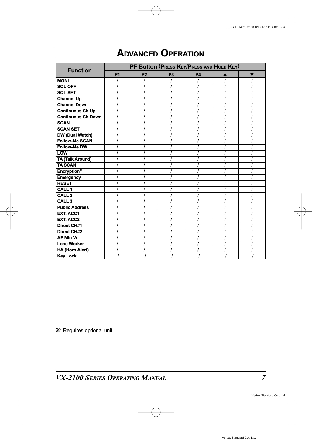
![VX-2100 SERIES OPERATING MANUAL6Automatic Time-Out TimerIf the selected channel has been programmed for automatic time-out, you must limitthe length of each transmission. While transmitting, a beep will sound 10 secondsbefore time-out. Another beep will sound just before the deadline; the red “TX”indicator will disappear and transmission will cease soon thereafter. To resume trans-mitting, you must release the PTT switch and wait for the “penalty timer” to expire(if you press the PTT switch before this timer expires, the timer restarts, and you willhave to wait another “penalty” period)Key LockIn order to prevent accidental frequency change or inadvertent transmission, variousaspects of the VX-2100’s keys may be locked out.To activate the Locking feature, press and hold in the [P1] key while turning theradio on. To disable the Locking feature, repeat this power-on procedure.ADVANCED OPERATIONProgrammable Function (PF) ButtonsThe VX-2100 Series includes six Programmable Function (PF) Buttons. The PFbutton functions can be customized, via programming by your VERTEX STAN-DARD dealer, to meet your communications/network requirements. Some featuresmay require the purchase and installation of optional internal accessories. The pos-sible PF button programming features are illustrated below, and these functions areexplained on the pages to follow.For further details, contact your VERTEX STANDARD dealer. For future reference,check the box next to the function that has been assigned to each PF button on yourparticular radio, and keep it handy.BASIC OPERATION OF THE TRANSCEIVERVertex Standard Co., Ltd.FCC ID: K6610613030/IC ID: 511B-10613030Vertex Standard Co., Ltd.](https://usermanual.wiki/Yaesu-Musen/10613030.USERS-MANUAL-1/User-Guide-741160-Page-8.png)
![VX-2100 SERIES OPERATING MANUAL8Description of Operating FunctionsMONITOR (MONI)Press (or press and hold) the assigned programmable key to cancel CTCSS- andDCS-controlled squelch; the TX/BUSY indicator will glow greenSQUELCH (SQL) OFFPress (or press and hold) the assigned programmable key to open the SQL to hearbackground noise (unmute the audio); the TX/BUSY indicator will blink green.SQUELCH (SQL) SETYou can manually adjust the squelch level using this function:Press (or press and hold) the assigned programmable key. A tone will sound, andthe current squelch will level appears on the display.Press the []/[] button to select the desired squelch level.Press this key again. A tone will sound, and the display will revert to the normalchannel indication.CHANNEL UP/DOWNPress (or press and hold) the assigned programmable key to select a different chan-nel.CC UP/DOWN (CONTINUOUS CH UP/DOWN)Press and holding in the assigned programmable key causes the radio to begin step-ping (repeatedly) upward or downward through the channels.ADVANCED OPERATIONVertex Standard Co., Ltd.FCC ID: K6610613030/IC ID: 511B-10613030Vertex Standard Co., Ltd.](https://usermanual.wiki/Yaesu-Musen/10613030.USERS-MANUAL-1/User-Guide-741160-Page-10.png)