Yaesu Musen 10614740 MOBILE TWO-WAY RADIO User Manual p65
Yaesu Musen Co., Ltd. MOBILE TWO-WAY RADIO p65
UserManual.wiki
>
Yaesu Musen
>
10614740 User Manual
users manual
Navigation menu
Upload a User Manual
Namespaces
Wiki Guide
HTML
PDF
Info
Views
User Manual
Discussion / Help
Navigation
![VX-2200 SERIES OPERATING MANUAL2CONTROLS & CONNECTORSFront PanelImportant! - All buttons located on the Front Panel are Programmable Function (PF)Buttons, configured according to your network requirements and programmed byyour VERTEX STANDARD dealer. The instructions below describe a typically-configured radio.VOL/PWR KnobTurn this control clockwise to turn the radio on and to increase the volume. Turnit counterclockwise into the click-stop to turn the radio off.Microphone JackConnect the microphone plug to this jack.[P1] - [P1] Buttons (Programmable Function Buttons)These buttons can be set up for special applications, such as High/Low powerselection, Monitor, Talk-Around, etc., as determined by your network require-ments and programmed by your VERTEX STANDARD dealer.[]/[] Buttons (Programmable Function Buttons)Pressing either button changes the current channel (and displayed channel num-ber or name). Holding in either button for more than 1.5 second causes the radioto begin stepping (repeatedly) upward or downward through the channels.P2P1 P3 P4Vertex Standard Co., Ltd.FCC ID: K6610614740/IC ID: 511B-10614740](https://usermanual.wiki/Yaesu-Musen/10614740/User-Guide-666365-Page-4.png)
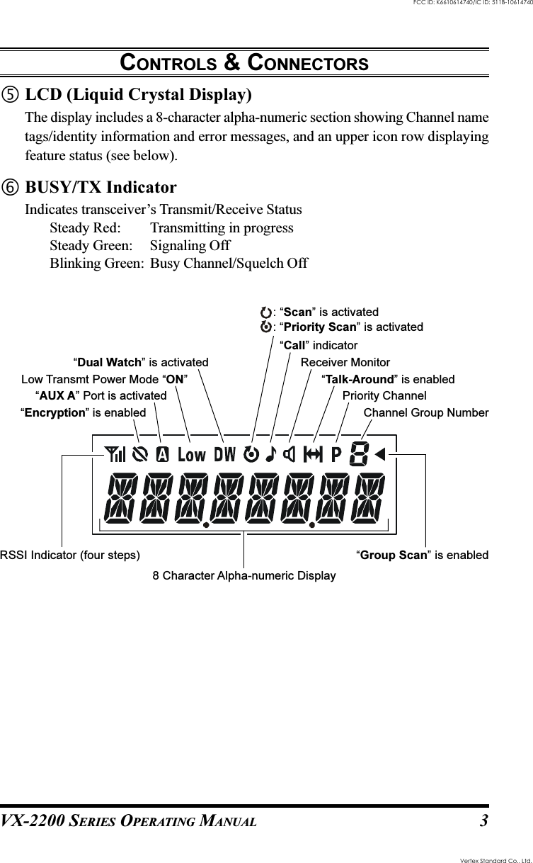
![VX-2200 SERIES OPERATING MANUAL 5BASIC OPERATION OF THE TRANSCEIVERImportant! - Before turning on the radio the first time, confirm that the power con-nections have been made correctly and that a proper antenna is connected to theantenna jack.Switching Power ON/OFFTurn the VOL/PWR knob turn on the radio. The display will become illumi-nated.Press the []/[] button to choose the desired operating channel. A channelname will appear on the display. If you want to select an operating channel froma different group, press the PF (Programmable Function) button which is pro-grammed to the Group Up/Down feature to select the group you want beforeselecting the operating channel. See page 7 for more information on the Pro-grammable Function keys.Setting the VolumeTurn the VOL/PWR knob clockwise to increase the volume, and counterclock-wise to decrease it.TransmittingTo transmit, monitor the channel and make sure it is clear.THIS IS AN FCC REQUIRMENT!Press the PF button which is programmed to the Monitor feature to listen forchannel activity.When receiving a call, transmit only after the incoming call ends. The radiocannot receive a call and transmit simultaneously.Press the PTT switch.If the channel is clear, the BUSY/TX indicator will glow red. The radio is nowtransmitting. While holding in the PTT switch, speak across the face of the micro-phone in a clear and normal voice. For best transmission, hold the microphoneabout 1-1/2 to 2 inches away from your mouth. Release the PTT switch to receive.If the Busy Channel Lockout feature has been programmed on a channel, theradio will not transmit when a carrier is present. Instead, the radio will generatea short beep three times and indicate “* ERROR *” on the display. Release thePTT switch and wait for the channel to be clear of activity.If CTCSS or Digital Coded Squelch (DCS) Lockout has been programmed on achannel, the radio can transmit only when there is no carrier being received orwhen the carrier being received includes the correct CTCSS tone or DCS code.Vertex Standard Co., Ltd.FCC ID: K6610614740/IC ID: 511B-10614740](https://usermanual.wiki/Yaesu-Musen/10614740/User-Guide-666365-Page-7.png)
![VX-2200 SERIES OPERATING MANUAL6Automatic Time-Out TimerIf the selected channel has been programmed for automatic time-out, you must limitthe length of each transmission. While transmitting, a beep will sound 10 secondsbefore time-out. Another beep will sound just before the deadline; the red “TX”indicator will disappear and transmission will cease soon thereafter. To resume trans-mitting, you must release the PTT switch and wait for the “penalty timer” to expire(if you press the PTT switch before this timer expires, the timer restarts, and you willhave to wait another “penalty” period)Key LockIn order to prevent accidental frequency change or inadvertent transmission, variousaspects of the VX-2200’s keys, and PTT switch, may be locked out. The preciselockout configuration may be configured using the “User Set” (Menu) mode. Seepage 16 for detail.To activate the Locking feature, press and hold in the [P4] key while turning theradio on. To disable the Locking feature, repeat this power-on procedure.BASIC OPERATION OF THE TRANSCEIVERVertex Standard Co., Ltd.FCC ID: K6610614740/IC ID: 511B-10614740](https://usermanual.wiki/Yaesu-Musen/10614740/User-Guide-666365-Page-8.png)
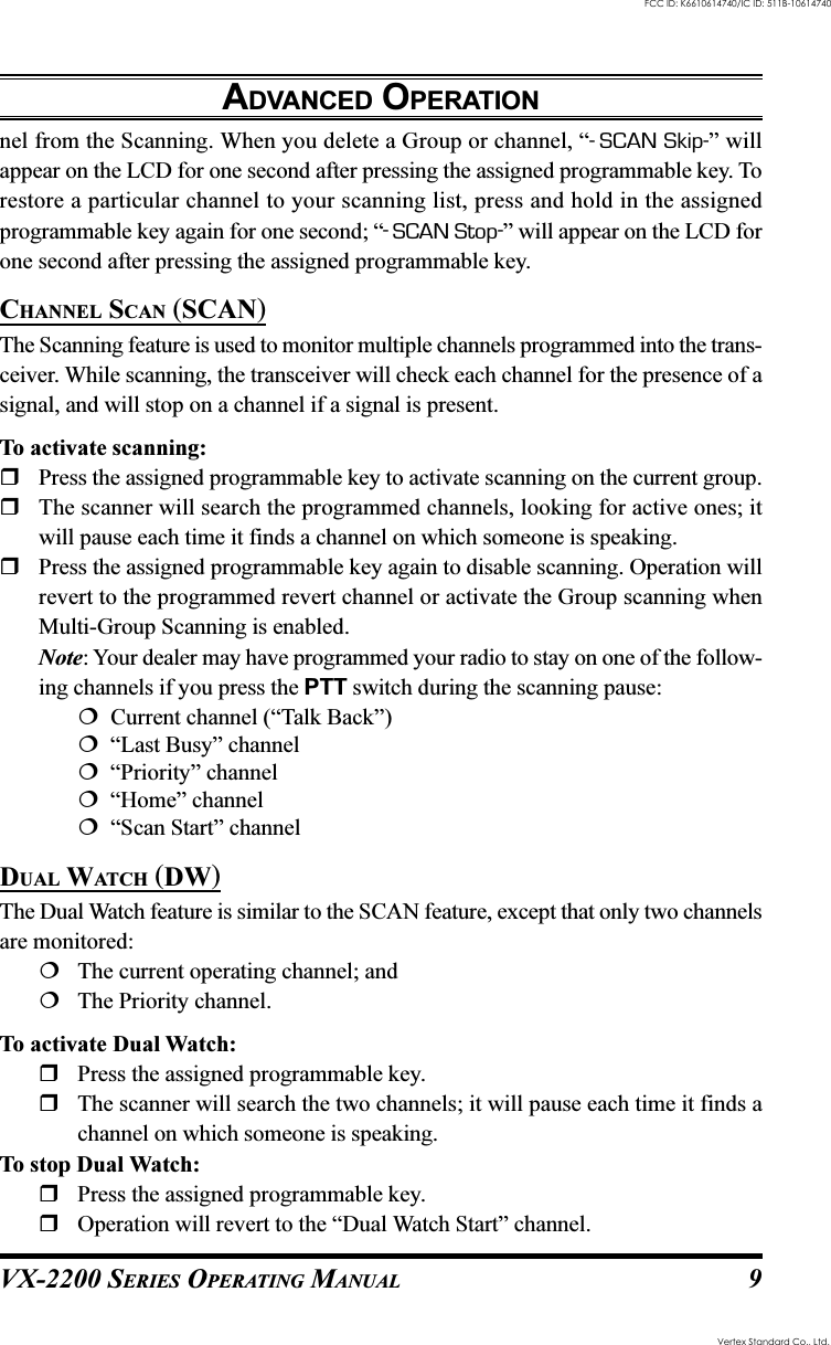
![VX-2200 SERIES OPERATING MANUAL8Description of Operating FunctionsMONITOR (MONI)Press the assigned programmable key to cancel CTCSS- and DCS-controlled squelch;the BUSY/TX indicator will glow green. Press and hold in this button for 1.5 sec-onds to hear background noise (unmute the audio); the BUSY/TX indicator willblink green.SQUELCH (SQL)You can manually adjust the squelch level using this function:Press the assigned programmable key. A tone will sound, and the current squelchwill level appears on the display.Press the []/[] button to select the desired squelch level.Press this key again. A tone will sound, and the display will revert to the normalchannel indication.DIMMERPress the assigned programmable key to select the brightness level of the display andkey backlight. Available selections are four levels.CHANNEL UP/DOWNPress the assigned programmable key (generally the []/[] button) to select adifferent channel within the current group.GROUP UP/DOWNPress the assigned programmable key to select a different group of channels. Oncethe desired Group is reached, press the Channel Up/Down key (generally the []/[] button) to select the desired channel within the selected Group.You may wish to have the Scanner pass through more than one Group during thescanning process (normally, scanning is performed within the current group only). Toinclude the current Group in the scanning loop, press and hold in the assignedprogrammable key for one second. To remove a Group from Group Scan, press andhold in the assigned programmable key again for one second.Multi-Group Scanning is only possible if you are using the “User Scan” list. To editthe User Scan list, press and hold the assigned programmable key for one second todelete the current Memory Group from the Scanning. Alternatively, press and holdthe assigned programmable key for one second to delete the Current Memory chan-ADVANCED OPERATIONVertex Standard Co., Ltd.FCC ID: K6610614740/IC ID: 511B-10614740](https://usermanual.wiki/Yaesu-Musen/10614740/User-Guide-666365-Page-10.png)
![VX-2200 SERIES OPERATING MANUAL10FOLLOW-ME SCAN“Follow-Me” Scan feature checks a User-assigned Priority Channel regularly as youscan the other channels. Thus, if only Channels 1, 3, and 5 (of the 8 available chan-nels) are designated for “Scanning,” the user may nonetheless assign Channel 2 asthe “User-assigned” Priority Channel via the “Follow-Me” feature.To activate “Follow-Me” scanning, first select the channel you want to designate asthe “User-Assigned Priority Channel” and press the assigned programmable key.Then press the Channel Up/Down key (generally the []/[] button) to recall to the“Scanning Start” channel which has been programmed by your dealer to activate thescanner. When the scanner stops on an “Active” channel, the User-assigned PriorityChannel will automatically be checked every few seconds; if activity is found on theUser-assigned Priority Channel, the radio will switch between it and the Dealer-As-signed Priority Channel, if any.FOLLOW-ME DUAL WATCH (DW)To set up a “Dual Watch” frequency pair using the “Follow-Me” feature, select achannel using the Channel Up/Down key (generally the []/[] button). Now pressthe assigned programmable key; pressing the assigned programmable key locks thecurrent channel as the User-assigned Priority Channel. Now press the Channel Up/Down key to select another channel (not the “Scanning Start” channel). Your radiowill now switch back-and-forth between the currently-selected channel and the User-assigned Priority Channel.During “Follow-Me” scanning (after you have pressed the key), you can set up the“Dual Watch” feature by pressing the Channel Up/Down key to another channel. Theradio will then scan back and forth between the original User-assigned Priority Channeland the newly-selected channel.The Priority Channel you have assigned (before pressing the key) will be retained inmemory until you change it.LOW POWER (LOW)Press the assigned programmable key to set the radio’s transmitter to the “Low Power”mode, thus extending battery life. Press the key again to return to “High Power”operation when in difficult terrain.When the radio’s transmitter is set to “Low Power” mode, the “ ” icon will beindicated on the display.ADVANCED OPERATIONVertex Standard Co., Ltd.FCC ID: K6610614740/IC ID: 511B-10614740](https://usermanual.wiki/Yaesu-Musen/10614740/User-Guide-666365-Page-12.png)
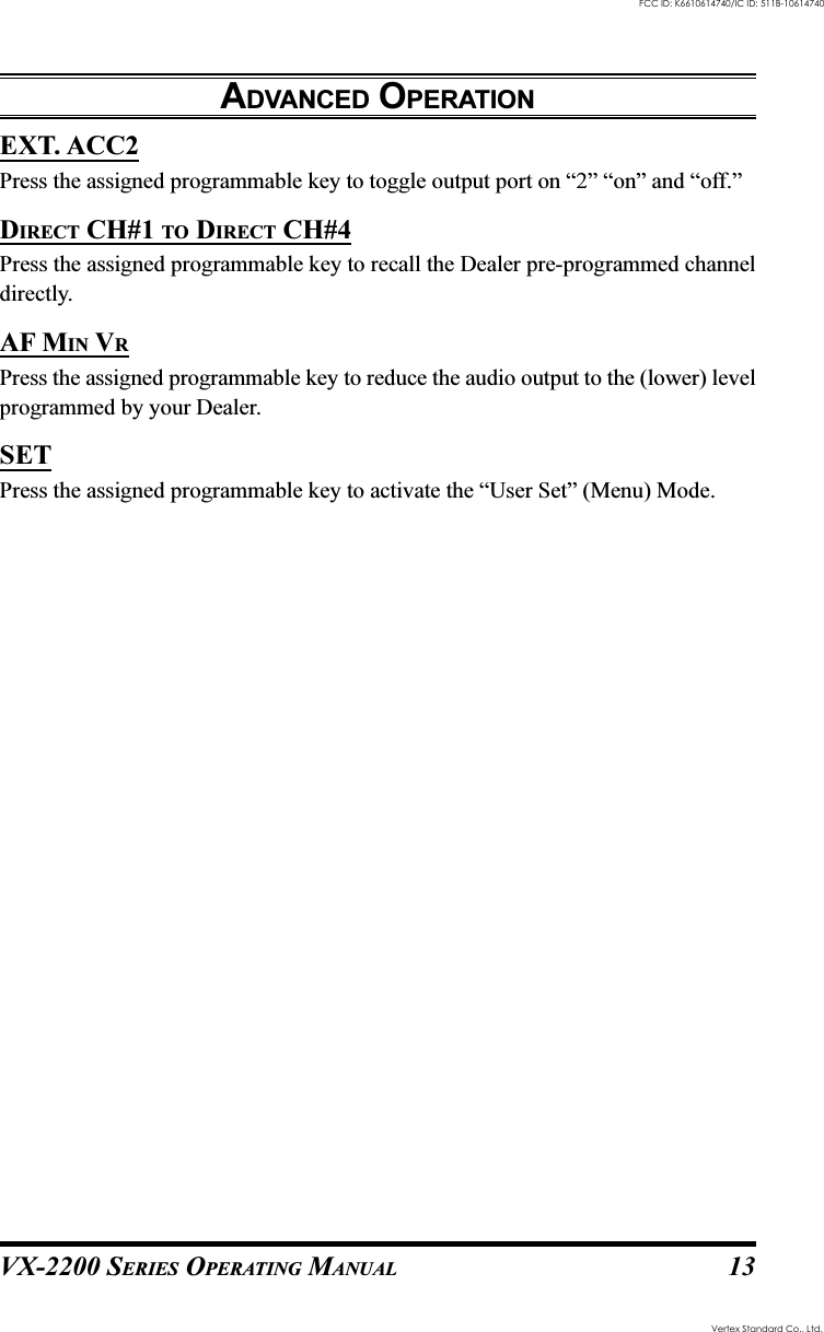
![VX-2200 SERIES OPERATING MANUAL12CODE UP/DOWNPress the assigned programmable key to select a 5-Tone encode code from pre-de-fined encode list.CODE SETPress the assigned programmable key to change the 5-Tone encodeing digit. To changethe tones, select the desired digit using the [P1]/[P2] keys, then change the numberusing the []/[] keys.STATUS UP/DOWNPress the assigned programmable key to select a 5-Tone status code from the pre-defined status list.SPEED DIALYour Dealer may have pre-programmed Auto-Dial telephone number memories intoyour radio.To dial a number, press the assigned programmable key, then press the microphone’snumbered key corresponding to the Auto-Dial memory number list provided by yourDealer. The DTMF tones sent during the dialing sequence will be heard in the speaker.HOME CHANNEL (HOME)Press the assigned programmable key to recall the pre-defined Home group/channel.When you recall the Home group/channel, the “H” icon will appear on the LCD.SELECTABLE TONEPress the assigned programmable key to select a sub-audible tone (CTCSS/DCS)from the pre-defined tone table. You can operate the indicated sub-audible tone inSelectable Tone mode.PUBLIC ADDRESSPress the assigned programmable key to use the transceiver as a PA amplifier. Whenyou enable this function, a tone sounds and “Public ADRS” will appear on the dis-play. The public address can be used even while scanning and receiving a call.EXT. ACC1Press the assigned programmable key to toggle output port on “1” “on” and “off.”ADVANCED OPERATIONVertex Standard Co., Ltd.FCC ID: K6610614740/IC ID: 511B-10614740](https://usermanual.wiki/Yaesu-Musen/10614740/User-Guide-666365-Page-14.png)
![VX-2200 SERIES OPERATING MANUAL 15USER SET MODEThe VX-2200 Series includes a “User Set” (Menu) Mode which allows the user todefine or configure various settings, such as Squelch, Display contrast, etc. To acti-vate the “User Set” (Menu) Mode:Press the programmable key assigned to the “SET” function.Select the User Set Mode item you wish to change using the [P1]/[P2] keys,then use the []/[] keys to adjust the setting of the selected item.Press the [P1] or [P2] key to store the new configuration.Press the programmable key assigned to the “SET” function to exit to normaloperation. DISPLAY DESCRIPTION1 SCN List Select the “User” or “Dealer” Scan List.2 BEEP Enables/Disables the Key Beeper.3 BELL Enables/Disables the Bell function.(alert tone activated by incoming subaudible CTCSS/DCS tone)4 Lighting Enables/Disables the BUSY/TX LED.5 Lock Set the Control Key Lockout Cofiguration (Key/PTT/Key+PTT).6 Group Select the desired Channel Group.7 SCAN Engages/Disengages Scanning (same as the programmable [SCAN] key).8DW Engages/Disengages Dual Watch (same as the programmable [DW] key).9TA Engages/Disengages Talk Around (same as the programmable [TA ] key).10 Encrypt Enables/Disables the disabling the Encryption Unit temporarily.ENB: Enables the disabling the Encryption Unit.DIS: Disables the disabling the Encryption Unit.11 AF MinVR Sets the minimum Audio Volume level.12 Beep VR Sets the Beep Volume level.13 Contrast Sets the LCD Contrast level.14 Dimmer Sets the brightness of the backlighting of the key and LCD.Vertex Standard Co., Ltd.FCC ID: K6610614740/IC ID: 511B-10614740](https://usermanual.wiki/Yaesu-Musen/10614740/User-Guide-666365-Page-17.png)