Yaesu Musen 10723X20 PORTABLE RADIO User Manual FCC ID K6610723X20
Yaesu Musen Co., Ltd. PORTABLE RADIO FCC ID K6610723X20
UserManual.wiki
>
Yaesu Musen
>
10723X20 User Manual
USERS MANUAL
Navigation menu
Upload a User Manual
Namespaces
Wiki Guide
HTML
PDF
Info
Views
User Manual
Discussion / Help
Navigation

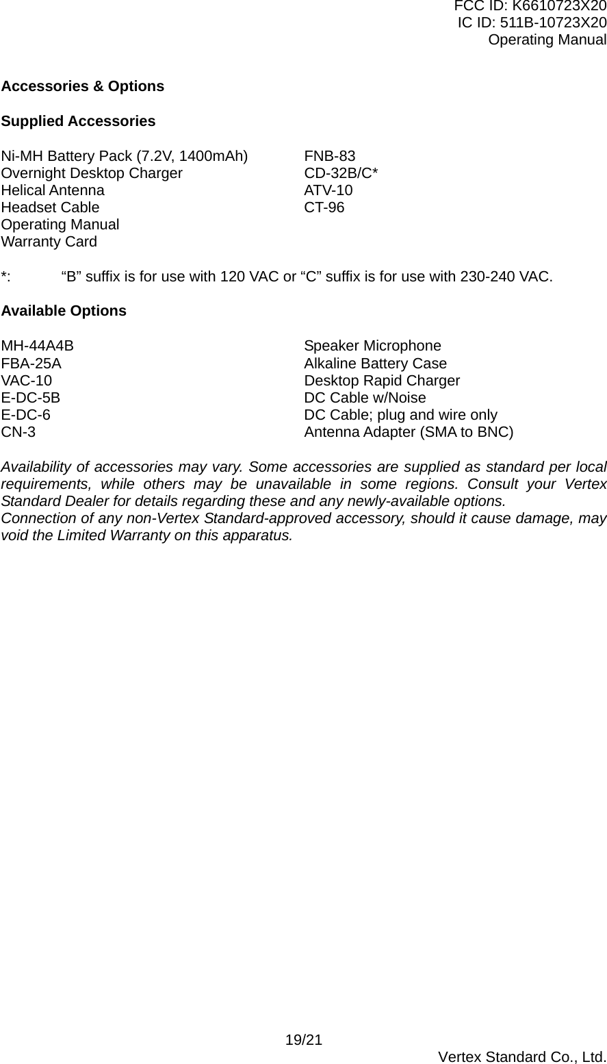
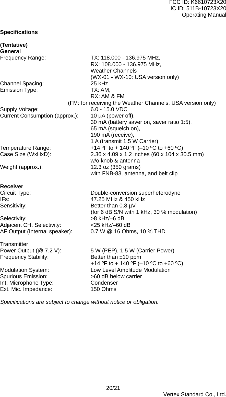
![FCC ID: K6610723X20 IC ID: 511B-10723X20 Operating Manual Controls & Connectors (Top Panel) Antenna Jack This SMA jack accepts the supplied flexible antenna, or another antenna designed to provide 50 Ohm impedance on the Aircraft Communication Band. MIC/EAR Jack You may connect the supplied CT-96 Headset Cable or the (optional) MH-44B4B Speaker/Microphone to this jack. Never connect any Speaker/Microphone that is not recommended by the manufacturer. Because these jack connections are unique, using a Speaker/Microphone that is not specified by Vertex Standard may damage the VXA-220. DIAL Selector Knob This (outer) 20-position detented rotary switch tunes the operating frequency or selects the memory channels. This rotary switch also adjusts the audio volume level by the setting of the Secondary function of the [5(DIAL/▲▼)] key. See page ?? for details. Controls & Connectors (Front Panel) BUSY/TX Indicator Lamp This lamp glows green when a signal is being received, and red when transmitting. Loudspeaker The internal speaker is located in this position. Microphone Speak across this opening in a normal voice level, while pressing the PTT switch, to transmit. LCD (Liquid Crystal Display) The display shows selected operating conditions, as indicated on the next page. Keypad The keypad is used for most radio command operations. Several keys have triple functions. The primary functions are labeled on the key top (activated by simply pressing the key momentarily). The secondary functions are labeled in yellow above the top edge of the key (activated by pressing the [F] key first, then the indicated key). The third functions are labeled in black above the top edge of the key (activated by pressing and holding in the indicated key for 2 seconds). These functions are described in detail on page ??. 2/21 Vertex Standard Co., Ltd.](https://usermanual.wiki/Yaesu-Musen/10723X20/User-Guide-736430-Page-2.png)
![FCC ID: K6610723X20 IC ID: 511B-10723X20 Operating Manual Primary Function (Press Key) Secondary Function (Press [F] + key) Third Function (Press and Hold key for 2 sec.) [1] Frequency Entry Digit 1 None None [2)] Frequency Entry Digit 2 None None [3] Frequency Entry Digit 3 None None [4(TIMER)] Frequency Entry Digit 4 Activates the Stop Watch Timer. None [5(DIAL/)] Frequency Entry Digit 5 Exchange the functions of the DIAL and ▲▼keys. None [6(DW)] Frequency Entry Digit 6 Activates the Dual Watch feature. Activates the VOX feature. [7(SPL)] Frequency Entry Digit 7 Activates Split (Duplex) mode. None [8(Beep)] Frequency Entry Digit 8 on/off Switch for Keypad Beeper None [9(SKIP)] Frequency Entry Digit 9 Allows Skipping of Channel during Scan. None [0(ANL)] Frequency Entry Digit 0 Activates the Automatic Noise Limiter. None [121.5] Selects Emergency Channel (121.5 MHz). None None [XFER(LOCK)] Selects the Memory Display Type. Switches the VFO mode “A” and “B.” Activates the Set (Menu) mode. Activates the Scanner. [ENT(LOCK)] Select the tuning methods among the VFO, MR, BMR, and WX. Activates the Key Lockout feature. [MW(SPL-W)] None Split-Memory “Write” Command. Memory “Write” Command. [F] Activates the “Secondary” key function. Disable the “Secondary” key function. None [] Increase the audio level or select the operating channel* None None [] Decrease the audio level or select the operating channel* None None *: Depends on setting of the Secondary function of the [5(DIAL/)] key. See page ?? for details. Battery Pack Latch Open this latch for battery removal. 3/21 Vertex Standard Co., Ltd.](https://usermanual.wiki/Yaesu-Musen/10723X20/User-Guide-736430-Page-3.png)
![FCC ID: K6610723X20 IC ID: 511B-10723X20 Operating Manual Battery Charging It is necessary to charge the Ni-MH battery fully before its first use. Follow these procedures: Install the supplied FNB-83 Ni-MH battery pack onto the transceiver. Ensure that the transceiver is switched off. Plug the CD-32 into the AC line outlet. Insert the transceiver and battery pack into the CD-32; the antenna jack should be at the left side when viewing the charger from the front. If the transceiver and battery pack are inserted correctly, the RED indicator will glow. A fully-discharged pack will be charged completely in 10 hours. Important Notes: The CD-32 is not designed to power the transceiver for operation (reception or transmission). Do not leave the charger connected to the transceiver for continuous periods in excess of 24 hours. Long term overcharging can degrade the Ni-MH battery pack and significantly shorten its useful life. If using a charger other than the CD-32, or if using a battery pack other than the FNB-83, follow the appropriate instructions provided with the charger/battery. Contact your Dealer if you have any doubts about the appropriateness of the particular charger or battery pack you intend to use. Low Battery Indication As your battery discharges during use, the voltage will gradually become lower. When the battery voltage reaches 6.0 Volts, the “BATTERY” icon will blink on the LCD display, indicating that the battery pack must be recharged before further use. Avoid recharging Ni-MH batteries before the “Low Battery” indicator is observed, as this can degrade the charge capacity of your Ni-MH battery pack. Vertex Standard recommends that you carry an extra, fully-charged pack with you so you will not lose communications capability due to a depleted Ni-MH battery. Installing the FBA-25 (option) Alkaline Battery Case The optional FBA-25 Battery Case allows operation of the VXA-220 using six “AA” size Alkaline batteries. When installing batteries, insert the (–) end first, then press in the (+) end so the battery snaps into place. Always replace all six batteries at the same time, paying attention to the polarity indicated inside the case. The FBA-25 must not be used with rechargeable cells. The FBA-25 does not contain the thermal and over-current protection circuits (provided in the “FNB” series of Ni-MH Battery Packs) required when utilizing Ni-Cd and Ni-MH cells. Basic Operation Preliminary Steps Install a charged battery pack onto the transceiver, as described previously. Screw the supplied antenna onto the Antenna jack. Never operate this transceiver without an antenna connected. If you have an optional Speaker/Microphone or headset, we recommend that it not be connected until you are familiar with the basic operation of the VXA-220. Operation Quick Start To turn the radio on, press and hold in the [POWER] Switch of for 3seconds. 5/21 Vertex Standard Co., Ltd.](https://usermanual.wiki/Yaesu-Musen/10723X20/User-Guide-736430-Page-5.png)
![FCC ID: K6610723X20 IC ID: 511B-10723X20 Operating Manual A channel frequency should appear on the display. If not, press the [ENT] key (repeatedly, if necessary) so that “- VFO -” appears on the display, followed by a channel frequency. Directly entering frequencies from the keypad is the easiest method if you know the frequency on which you wish to operate. Just enter the five digits of the frequency to move to that frequency. For example, to set 134.35 MHz, press [1] [3] [4] [3] [5]. To set 118.275 MHz, you do not need to press the final “5” in the frequency: [1] [1] [8] [2] [7]. You may also turn the top panel’s DIAL selector knob*1 to choose the desired operating frequency. The channel frequency will appear on the LCD. Press the []/[] key*2 to set the volume level. If no signal is present, press and hold the MONITOR button for 2 seconds; background noise will now be heard, and you may use this noise to set the desired audio level. Press the [MONITOR] button momentarily to silence the noise and resume normal (quiet) monitoring. To turn the radio off, press and hold in the [POWER] switch for 3 seconds. *1: If you change a function of DIAL and []/[] key by pressing the [F] key followed by the [5(DIAL/)] key, you may choose the operating frequency by pressing the []/[] key. *2: If you change a function of DIAL and []/[] key by pressing the [F] key followed by the [5(DIAL/)] key, you may set the volume level by turning the DIAL selector knob. Squelch Adjustment Press the [F] key momentarily, then press the [XFER(SET)] key to activate the Menu (SET) mode. Rotate the DIAL selector knob to select Menu Item “SQL.” Press the [ENT(LOCK)] key to enable adjustment of this Menu item. Rotate the DIAL selector knob to set the squelch threshold (0 to 8) so that the receiver is just silenced. A higher number indicates that a higher signal level is required in order to open the squelch. Press the [ENT(LOCK)] key to save your new setting. Press the PTT switch to exit the Menu (“SET”) mode. Accessing the 121.5 MHz Emergency Frequency The VXA-220 can quickly access the 121.500 MHz Emergency Frequency. This function can be activated even when the keypad lock function (described on page ??) is in use. To access the Emergency Frequency, press the [121.5] key momentarily. To exit the Emergency Frequency, press the [ENT] key. Transmission To transmit, press and hold the PTT switch. Speak into the microphone area of the front panel grille in a normal voice level. To return to the receive mode, release the PTT switch. Advanced Operation Tuning Methods Throughout this manual, you will see references to several different frequency setting methods. Each will be particularly useful in a particular operating situation, and they are described below: VFO (Variable Frequency Oscillator) The VFO is a “tuning dial” system which allows you to tune through the NAV or COM bands using the DIAL selector knob, the Keypad, or the scanner. The VXA-220 has two VFOs which are called VFO-A and VFO-B. Press the [XFER(SET)] key momentarily to 6/21 Vertex Standard Co., Ltd.](https://usermanual.wiki/Yaesu-Musen/10723X20/User-Guide-736430-Page-6.png)
![FCC ID: K6610723X20 IC ID: 511B-10723X20 Operating Manual switch between VFO-A and VFO-B. You may set VFO-A to the NAV band, and VFO-B to the COM band, if you like. MR (Memory Recall) The MR (Memory Recall) mode of the VXA-220 provides the user with the ability to store and recall as many as 150 channels in the radio’s main memory bank. These memory channels may also be labeled by you with an alpha/numeric name of up to 8 characters in length, to aid in quick identification of the channel. See page ?? for details on creating alpha/numeric labels. BOOK (Pre-Programmed) Memories The Book memories are pre-programmed, either at the factory or by your Dealer (depending on your country’s requirements), typically including the major COM and NAV band station frequencies used in your area. The Book memories can be changed by the user. See page ?? for details. WX (Weather Channel) Memories (USA version only) Ten Weather Channels are pre-programmed at the factory. The VXA-220 will automatically scan this special bank when it is selected by the user. Reception of Weather Channel Broadcasts (USA version only) The VXA-220 can receive VHF Weather Channel broadcasts, which may assist your flight planning. The VXA-220 includes a ten-channel auto-search feature, which simplifies access to Weather Channels when you are in an unfamiliar location. To receive Weather Channels, press the [ENT(LOCK)] key (repeatedly, if necessary) to select the Weather Channel mode. In the Weather Channel mode, “- WX -” will appear on the display. The VXA-220 will now scan quickly through the ten standard Weather Channels, and will stop on the first active station found. If there are two or more weather channels audible in your area, you may select the alternate channel(s) by pressing the PTT switch. Pressing the PTT switch re-initiates the scanning process. If there are no Weather Channels in your area, the scanner will not stop. Press the MONITOR button to stop the scanner. You can also select Weather Channels manually by rotating the DIAL selector knob*. To confirm the current Weather Channel frequency, press the [XFER(LOCK)] key momentarily. The display changes to frequency indication. Press the [XFER(LOCK)] key again to return to normal display. To exit the Weather Channel mode, press the [ENT(LOCK)] key momentarily to return to the VFO mode. *1: If you change a function of DIAL and []/[] key by pressing the [F] key followed by the [5(DIAL/)] key, you may select Weather Channels by pressing the []/[] key. Note 1: In the event of extreme weather disturbances, such as storms and hurricanes, the NOAA (National Oceanic and Atmospheric Administration) sends a weather alert accompanied by a 1050 Hz tone and subsequent weather report on one of the NOAA weather channels. You may setup the Alert function when receiving the Weather Alert signal via Menu Item “WXAF,” if desired. See page ?? for details. Note 2: The Weather Channel mode memorizes the last Weather Channel you have used, and will retain this information until the radio is turned off. Monitor Key When listening to a very weak signal from an aircraft or ground station, you may observe the signal disappearing periodically as the incoming signal strength becomes too weak to override the squelch threshold setting. To disable the squelch temporarily, press and hold the MONITOR key for 2 seconds on the left side of the radio, just below the PTT button. The squelch will remain open and you should have a better chance of hearing weak signals. 7/21 Vertex Standard Co., Ltd.](https://usermanual.wiki/Yaesu-Musen/10723X20/User-Guide-736430-Page-7.png)
![FCC ID: K6610723X20 IC ID: 511B-10723X20 Operating Manual To return to normal operation, press the MONITOR key momentarily. ANL (Automatic Noise Limiter) Feature For reduction of impulse noise, such as that produced by an engine’s ignition system, the ANL feature may prove helpful. The ANL feature is only activated in the AM mode. To activate the ANL feature, press the [F] key followed by the [0(ANL)] key. The “ANL” icon will appear on the display, and you should observe a reduction in the ignition noise. To turn the ANL feature off, repeat the above step (press the [F] key followed by the [0(ANL)] key); the “ANL” icon will disappear from the display. LOCK Function The lock function prevents accidental changes to the frequency setting and the keypad controls. To activate the lock feature, press the [F] key followed by the [ENT(LOCK)] key. The “KEY” icon will appear on the display To turn the lock feature off, repeat the above step (press the [F] key followed by the [ENT(LOCK)] key); the “KEY” icon will disappear from the display. You can still access the 121.500 MHz Emergency Frequency when the LOCK function is on. Simply press the [121.5] key momentarily (this key never locks). Pressing this key also unlocks the radio. You may choose the lockout configuration according to your operating preferences. See page ?? for details. DIAL and []/[] key Swap Configuration In the factory default, the DIAL selector knob selects the operating frequency and the memory channel, and the []/[] key adjust the audio volume level. However, you may exchange the function of the DIAL selector knob and []/[] key; as a result, adjust the audio volume level by the DIAL selector knob, and selects the operating frequency and the memory channel by the []/[] key. Press the [F] key followed by the [5(DIAL/)] key to toggle the DIAL and []/[] key configurations. Receive Battery Saver Setup An important feature of the VXA-220 is its Receive Battery Saver, which “puts the radio to sleep” for a time interval, periodically “waking it up” to check for activity. If somebody is talking on the channel, the VXA-220 will remain in the “active” mode, then resume its “sleep” cycles. This feature significantly reduces quiescent battery drain, and you may change the amount of “sleep” time between activity checks using the Menu System: Press the [F] key followed by the [XFER(SET)] key to activate the Menu (“SET”) mode. Rotate the DIAL selector knob to select Menu Item “RSAV.” Press the [ENT(LOCK)] key to enable adjustment of this Menu Item. Rotate the DIAL selector knob to select the desired “duty cycle” (receive:sleep). The selections available are 1:1, 1:2, 1:3, 1:4, 1:5, and ABS* or oFF. The default value is 1:1. When you have made your selection, press the [ENT(LOCK)] key to save the new setting, and then press the PTT key to exit to normal operation. *ABS: Automatic Battery Saver, based on activity on the receiver. The setting of 1:5 will promote the greatest conservation of battery capacity, but the receiver’s response time to incoming calls will be slowed somewhat. Note: This feature does not operate during Scan or Dual Watch. 8/21 Vertex Standard Co., Ltd.](https://usermanual.wiki/Yaesu-Musen/10723X20/User-Guide-736430-Page-8.png)
![FCC ID: K6610723X20 IC ID: 511B-10723X20 Operating Manual Beep On/Off The VXA-220’s key/button beeper provides convenient audible feedback whenever a button is pressed. Each key and button has a different beep pitch, and each function has a unique beep combination. When you are scanning, the beeper will be heard each time the scanner halts on a busy channel. This may be distracting in some environments; if you want to turn the beeper off (or back on again): To disable the beeper, press the [F] key followed by the [8(BEEP)] key. The “BEEP OFF” notation will appear on the display for 3 seconds. To turn the beep on, repeat the above step (press the [F] key followed by the [8(BEEP)] key); the “BEEP ON-” notation will appear on the display for 3 seconds. You may turn the beeper on and off via the Menu Item “BEEP.” Changing the Channel Steps The VXA-220’s synthesizer provides the option of utilizing channel steps of 8.33/25 kHz per step (default: 25 kHz). If you need to change the channel step size, the procedure to do so is very easy. First set the VXA-220 to the operating band (NAV or COM) on which you wish to change the channel steps. Press the [F] key followed by the [XFER(SET)] key to activate the Menu (“SET”) mode. Rotate the DIAL selector knob to select Menu Item “STEP.” Press the [ENT(LOCK)] key to enable adjustment of this Menu item. Rotate the DIAL selector knob to select the new channel step size. When you have made your selection, press the [ENT(LOCK)] key to save the new setting, and then press the PTT key to exit to normal operation. Important Note 1) When you select the channel step to 8.33 kHz, the channel display differs from actual operating frequency; see the chart below. However, the operator (pilot, tower, control, etc) will call out the frequency according to what the display indicates. Display Operating Frequency 8.33 kHz Step 25 kHz Step 1xx.0000 MHz 1xx.005 MHz 1xx.000 MHz1xx.0083 MHz 1xx.010 MHz1xx.0166 MHz 1xx.015 MHz1xx.0250 MHz 1xx.030 MHz 1xx.025 MHz1xx.0333 MHz 1xx.035 MHz1xx.0416 MHz 1xx.040 MHz1xx.0500 MHz 1xx.055 MHz 1xx.050 MHz1xx.0583 MHz 1xx.060 MHz1xx.0666 MHz 1xx.065 MHz1xx.0750 MHz 1xx.085 MHz 1xx.075 MHz1xx.0833 MHz 1xx.085 MHz1xx.0916 MHz 1xx.090 MHz2) The 8.33 kHz step allows the radio to receive only, and the transmit function is disabled. 3) The adjacent channel selectivity will be slightly degraded while receiving using 8.33 kHz channel steps. VOX Operation The VOX system provides automatic transmit/receive switching based on voice input to the microphone when using the after- market Headset. With the VOX system enabled, you do not need to press the PTT key in order to transmit, and it is not necessary to use a Headset 9/21 Vertex Standard Co., Ltd.](https://usermanual.wiki/Yaesu-Musen/10723X20/User-Guide-736430-Page-9.png)
![FCC ID: K6610723X20 IC ID: 511B-10723X20 Operating Manual in order to utilize VOX operation. Press and hold the [6(DW)] key for 3 seconds to activate the VOX system. The “VOX” icon will appear on the display. Without pressing the PTT key, speak into the microphone on the Headset in a normal voice level. When you start speaking, the transmitter should be activated automatically. When you finish speaking, the transceiver should return to the receive mode (after a short delay). To cancel VOX and return to PTT operation, press and hold the [6(DW)] key for 3 seconds; the “VOX” icon will disappear from the display. The VXA-220 provides for adjustment of the VOX Gain via the Menu, to prevent accidental transmitter activation in a noisy environment. To set the VOX Gain: Press the [F] key followed by the [XFER(SET)] key to activate the Menu (“SET”) mode. Rotate the DIAL selector knob to select Menu Item “VSNS.” Press the [ENT(LOCK)] key to enable adjustment of this Menu item. While speaking into the microphone on the Headset, rotate the DIAL selector knob to the point where the transmitter is quickly activated by your voice, without causing background noise to activate the transmitter. When you have selected the optimum setting, press the [ENT(LOCK)] key to save the new setting, and then press the PTT key to exit to normal operation. The VXA-220 also provides for adjustment of the “Hang-Time” of the VOX system (transmit-receive delay after the cessation of speech) via the Menu. The default delay is 0.1 second. To set a different delay time: Press the [F] key followed by the [XFER(SET)] key to activate the Menu (“SET”) mode. Rotate the DIAL selector knob to select Menu Item “VDLY.” Press the [ENT(LOCK)] key to enable adjustment of this Menu item. Rotate the DIAL selector knob to select the delay time among “05,” “10,” “15,” and “20” (representing 0.05, 0.1, 0.15, and 0.2 sec). When you have made your selection, press the [ENT(LOCK)] key to save the new setting, and then press the PTT key to exit to normal operation. Side Tone Feature (monitoring your voice) When using the after-market Headset, you may monitor your transmitted voice from the headset for monitoring. To set the side tone (monitor) level: Press the [F] key followed by the [XFER(SET)] key to activate the Menu (“SET”) mode. Rotate the DIAL selector knob to select Menu Item “STLV.” Press the [ENT(LOCK)] key to enable adjustment of this Menu item. Rotate the DIAL selector knob to select the desired monitoring level (1, 2, or 3). When you have made your selection, press the [ENT(LOCK)] key to save the new setting, and then press the PTT key to exit to normal operation. Timer Operation The VXA-220 is provided a “Stop Watch” timer and a “Count Down” timer. These can be used for a variety of time-keeping purposes. Press the [F] key followed by the [4(TIMER)] key to activate the Timer Mode. Press the [XFER(LOCK)] key toggle the Timer between the “Stop Watch” and “Count Down” timer modes. If you select the “Count Down” timer, rotate the DIAL knob to set the values for the timer (1 minutes - 60 minutes). The Timer is designed to start/stop/reset repeatedly whenever you press the [ENT(LOCK)] key. In the “Count Down” timer mode, an alert will sound and the timer will stop when the 10/21 Vertex Standard Co., Ltd.](https://usermanual.wiki/Yaesu-Musen/10723X20/User-Guide-736430-Page-10.png)
![FCC ID: K6610723X20 IC ID: 511B-10723X20 Operating Manual “Count Down” timer reaches “00 00 00.” To disable the Timer Mode, press the [F] key followed by the [4(TIMER)] key again. Memory Operation The VXA-220 provides 150 user-programmable “Main” memories, labeled “CH-001” through “CH-150,” and up to 100 pre-programmed memories, designated “Book” Memories. The “BOOK” icon appears when the “Book” Memory Mode is activated. The Main memories and “Book” Memories can be assigned alpha-numeric names of up to eight characters. Memory System Operation The VXA-220’s Main Memory system allows the user to store, label, and recall channel frequencies which you may want to use frequently. You may store VFO frequencies, Book Memory frequencies, and/or Weather Channel frequencies (USA version only) into the Main Memory system. Memory Storage Select the desired frequency in the VFO mode, or recall the Book Memory channel or Weather channel to be stored in the Main Memory. Press and hold in the [MW(SPL-W)] key for 2 seconds. The display will indicate “CH-XXX” and a channel number will blink on the LCD. Within five seconds of pressing the [MW(SPL-W)] key, rotate the DIAL selector knob to select the desired memory channel number for storage. In order to prevent writing over memory channels, an “underline” will appear under the hyphen (located between “CH” and the channel number) to indicate a vacant memory channel. Now press and hold in the [MW(SPL-W)] key for 2 seconds; you will now see “A - - - - - - -” on the LCD. To attach an alpha/numeric name (label) to the memory, proceed to the next step; otherwise press and hold in [MW(SPL.W)] for 2 seconds to save the entry and exit. To label a memory with an alpha/numeric name, the next step is to use the DIAL selector knob to select any of the 48 available characters (including letters, numbers, and special symbols). When the desired first character appears, press the [ENT(LOCK)] key momentarily to move on to the next character. Select succeeding characters in the same manner, pressing the [ENT(LOCK)] key momentarily after each selection. After entering the entire name (eight characters maximum), press the [MW(SPL-W)] key for 2 seconds to save all data for the channel and exit. Note: If you have transferred a Weather Channel directly to memory, the “WX-01 ~ WX-10” labels utilize the alphanumeric memory, and other labels may not be stored. Recalling the Memories Press the [ENT(LOCK)] key, repeatedly if necessary, until “- MR -” (Memory Recall) appears on the display. In the MR mode, you will see “CH-” and the previously selected channel number appearing on the LCD. Rotate the DIAL selector knob* to select the desired memory channel. You may change the title structure of the Memory display type among: 1. Channel Indication (sequential Channel Number, e.g. CH-001, CH-002, etc.); 2. Frequency Indication (e.g. 122.500); or 3. Alphanumeric Label (e.g. LAX FSS). To change the Memory display title, press the [XFER(LOCK)] key repeatedly, if necessary, until you get the desired display title structure. To exit the Memory mode, press the [ENT(LOCK)] key three times to return to the VFO 11/21 Vertex Standard Co., Ltd.](https://usermanual.wiki/Yaesu-Musen/10723X20/User-Guide-736430-Page-11.png)
![FCC ID: K6610723X20 IC ID: 511B-10723X20 Operating Manual mode. *: If you change a function of DIAL and []/[] key by pressing the [F] key followed by the [5(DIAL/)] key, you may select the memory channel by pressing the []/[] key. Deleting Memories You may delete any of the memories (except for memory channel “001”). The procedure for deleting a channel is quite simple. Press the [F] key followed by the [XFER(SET)] key to activate the Menu (“SET”) mode. Rotate the DIAL selector knob to select Menu Item “MCLR.” Press the [ENT(LOCK)] key, then rotate the DIAL selector knob to recall the memory channel to be erased. Press the [ENT(LOCK)] key to clear the Memory channel (the Memory channel number will return to “001”). Important Notice: An “erased” channel cannot be restored, and “CH-001” cannot be erased, as it is used for “Priority Channel” operation. Scanning Operation The VXA-220 allows you to scan automatically in the VFO*1, Main Memory, “Book” Memory, or Weather Channel*2 modes. It pauses on signals encountered, so you can talk to the station(s) on that frequency, if you like. *1: In the VFO mode, the automatic scanner is only available in the COM band (118.000 - 136.975 MHz); when the scanner reaches the uppermost frequency in the COM band, it will revert to the bottom end of the COM band and repeat the scanning process until you cancel the scanning process. *2: USA version only. If you wish to scan in the NAV band (108.000 - 117.975 MHz), you can do so manually, as described below. Scanning operation is basically the same in each of the above modes. Press and hold in the [XFER(SET)] key for 2 seconds to start the automatic scanner upward (toward a higher frequency or a higher channel number). When the scanner encounters a signal, scanning pauses and the radio remains on that channel until one second after the signal disappears, after which scanning will resume. While the scanner remains paused on a frequency, the decimal point of the frequency displays blinks. The display will be illuminated unless the Scan Lamp Feature is turned off. To change the scan direction, turn the DIAL selector knob one click in the opposite direction.* To stop the automatic scanner, press the PTT switch or the [ENT(LOCK)] key momentarily. You may also just press the [XFER(SET)] key. *: If you change a function of DIAL and []/[] key by pressing the [F] key followed by the [5(DIAL/)] key, you may change the scan direction by pressing the []/[] key in the opposite direction. The VXA-220’s automatic scanner is not operational in the NAV band (108.000 - 117.975 MHz), because the NAV stations (ILS, etc.) transmit constantly (thereby causing the scanner to stop repeatedly). However, you can scan manually in the NAV band, per the following procedure: Press and hold the [XFER(SET)] key for 2 seconds to start the manual scanner. Scanning will continue as long as the key is depressed. Release the [XFER(SET)] key to stop the manual scanner immediately. Note: When scanning upward in frequency, when the frequency reaches the COM Band (118.000 - 136.975 MHz) via manual scanning, the VXA-220 will switch to the automatic scanner mode. 12/21 Vertex Standard Co., Ltd.](https://usermanual.wiki/Yaesu-Musen/10723X20/User-Guide-736430-Page-12.png)
![FCC ID: K6610723X20 IC ID: 511B-10723X20 Operating Manual Channel-Skip Scanning Continuous-carrier stations like ATIS (Automatic Terminal Information Service) or Weather Broadcast stations inhibit scanner operation. Since these stations are always active, the scanner will be halted repeatedly on their channels. Such channels can be set to be “skipped” during Memory scanning (MR, Book or WX modes), if you like, so as not to interfere with automatic channel scanning: Recall the Memory Channel to be skipped during scanning. Press the [F] key followed by the [9(SKIP)] key. The “SKIP” icon will appear on the display, indicating that the channel is to be ignored during scanning. You can also designate a channel to be skipped while scanning. When the receiver is halted on a channel that you wish to skip, press and hold the [SCAN(DW)] key for 2 seconds (the “SKIP” icon will appear next to the channel to be skipped). Later, to re-enable the memory channel for scanning, repeat the first two steps. The “SKIP” icon will disappear by the channel you have just re-enabled. Note: A memory set to be “skipped” is still accessible for manual memory selection using the DIAL selector knob or []/[] key, if you change a function of DIAL and []/[] key by pressing the [F] key followed by the [5(DIAL/)] key. Dual Watch Operation The Dual Watch feature automatically checks for activity on a “priority” channel* while you are operating on another channel. During Dual Watch operation, the current channel and the Priority channel will each be polled for a 500 ms interval, as the VXA-220 looks for activity on each channel. To start Dual Watch, press the [F] key followed by the [6(DW)] key. The “DW” icon will appear on the display. While receiving on the “current” channel (not the Priority channel), you may push the PTT switch at any time to transmit on that channel. When a signal is received on the Priority channel, operation immediately shifts to the Priority channel, the “DW” icon will blink, and the display will become illuminated. While receiving on the priority channel, if you momentarily press the PTT switch, Dual Watch will be disabled. You may then transmit on the Priority Channel. To stop Dual Watch, press [F] key followed by the [6(DW)] key. If you wish, you may use both the Dual Watch and Scan features simultaneously. To do this, start the Dual Watch first, then start the Scanner. *: The “priority” Channel is defined as the last-used Memory Channel (when using the VFO mode) or Memory Channel “001” (when using the Main Memory or Book Memory modes). Priority Dual Watch Operation Similar to Dual Watch operation (described on previous page), Priority Dual Watch is an enhanced version which includes the following additional features: The receiving time interval (ratio) between the current channel and the Priority channel may be customized via Menu Item “PRTM.” See page ?? for details. Irrespective of which channel is currently being received, when the PTT button is pushed transmission will always occur on the Priority channel. Before initiating Priority Dual Watch, Menu Item “DWMD” must be set to the “PRI: Priority” mode (instead of “DW: Dual Watch”). See page ?? for details. To start Priority Dual Watch, press [F] key followed by the [6(DW)] key. The “DW” icon will appear on the display. While receiving on the “current” (non-Priority) channel, pressing the PTT button once causes the radio to switch to the Priority channel and cancels Dual Watch. Press the PTT button again to transmit on the Priority channel. When a signal is received on the Priority channel, reception immediately shifts to the Priority channel, the “DW” icon will blink, and the display will become illuminated unless 13/21 Vertex Standard Co., Ltd.](https://usermanual.wiki/Yaesu-Musen/10723X20/User-Guide-736430-Page-13.png)
![FCC ID: K6610723X20 IC ID: 511B-10723X20 Operating Manual the Scan Lamp Feature is turned off. While receiving on the priority channel, if you momentarily press the PTT switch, Priority Dual Watch will be disabled. You may then transmit on the Priority Channel. To stop Priority Dual Watch, press [F] key followed by the [6(DW)] key. Split Operation The split operation feature allows you to transmit a call to a Flight Service Station using the COM band frequencies, while receiving an ATIS broadcast (in the NAV band). The ATIS broadcasts are used by airports to notify arriving and departing pilots of the current surface weather conditions, landing and departing runways, runway and taxiway conditions, communication frequencies and other information of importance to arriving and departing aircraft. Programming a Transmit Frequency Press the [ENT(LOCK)] key, repeatedly if necessary, to select the VFO mode. Set a NAV band (108.000 - 117.975 MHz) frequency, such as the ATIS broadcast using the DIAL selector knob* or keypad. Press the [F] key followed by the [MW(SPL-W)] key. The “SPL” icon will blink, and the transmit frequency will appear on the display. Now set your radio’s transmit frequency, where the Flight Service Station will be listening for calls, using the DIAL selector knob* or keypad. Press and hold in the [MW(SPL-W)] key for 2 seconds to save the transmit frequency and return to the NAV band frequency. *: If you change a function of DIAL and []/[] key by pressing the [F] key followed by the [5(DIAL/)] key, you may set the operating frequency by pressing the []/[] key. Note: You have now stored the separate transmit frequency, but you have not yet activated the split-frequency function; go on to the next section. Operating in the Split Mode It is assumed that you have already set the desired VOR station’s frequencies (in the NAV band) per the above instructions. Press the [F] key followed by the [7(SPL)] key to turn on the “Split” function. The “SPL” icon will appear on the display. Press and hold in the PTT switch to transmit on the split transmit frequency. Release the PTT switch to return to the receive mode. To disable the “Split” function, press the [F] key followed by the [7(SPL)] key again. Note: A split frequency can be programmed into each memory channel independently. Set a transmit frequency before programming the memory channel, if desired. The split function on/off setting can also be programmed into a memory channel. Field Programming Mode The VXA-220’s Book Memories also allow the user to store, label, and recall channel frequencies which you may want to use frequently while the VXA-220 is in the Field Programming mode. Memory Storage into the Book Memory Press and hold the PTT and [ENT(LOCK)] key while turning the radio on, to activate the Field Programming Mode. Select the desired frequency to be stored in the Book Memory. Press and hold in the [MW(SPL-W)] key for 2 seconds. The display will indicate “-BOOK –“ and a channel number will blink on the LCD. Within five seconds of pressing the [MW(SPL-W)] key, rotate the DIAL selector knob to select the desired memory channel number for storage. Now press and hold in the [MW(SPL-W)] key for 2 seconds; you will now see blinking 14/21 Vertex Standard Co., Ltd.](https://usermanual.wiki/Yaesu-Musen/10723X20/User-Guide-736430-Page-14.png)
![FCC ID: K6610723X20 IC ID: 511B-10723X20 Operating Manual “A” at the left side of the LCD. To attach an alpha/numeric name (label) to the memory, proceed to the next step; otherwise press and hold in the [MW(SPL-W)] key for 2 seconds to save the entry and exit. To label a memory with an alpha/numeric name, the next step is to use the DIAL selector knob to select any of the 48 available characters (including letters, numbers, and special symbols). When the desired first character appears, press the [ENT(LOCK)] key momentarily to move on to the next character. Select succeeding characters in the same manner, pressing the [ENT(LOCK)] key momentarily after each selection. After entering the entire name (eight characters maximum), press the [MW(SPL-W)] key for 2 seconds to save all data for the channel. Repeat this procedure to store additional frequencies into the Book Memory section, as desired. Turn the radio off, then turn the radio back on again to begin normal operation. CPU Resetting In some instances of erratic or unpredictable operation, the cause may be corruption of data in the microprocessor (due to static electricity, etc.). If this happens, resetting of the microprocessor may restore normal operation. Note that all memories will be erased if you do a complete microprocessor reset, as described below. To clear all memories and other settings to factory defaults: Turn the radio off. Press and hold in the [ENT(LOCK)] key and the MONITOR button, while turning the radio on. Menu (“Set”) Mode The Menu system allows certain aspects of your radio’s configuration to be customized for your personal operating convenience. We do not recommend that any of the default settings be changed, however, until you are thoroughly familiar with the operation of the VXA-220. 1. Press the [F] key followed by the [XFER(SET)] key to activate the Menu (“SET”) mode. 2. Rotate the DIAL selector knob to select the Menu Item (feature) you wish to view and/or modify. 3. Once you have selected the desired Menu Item, press the [ENT(LOCK)] key to enable adjustment of this Menu Item. The current setting value will be blinking. 4. Rotate the DIAL selector knob to change the setting of the item (“on” to “oFF,” etc.). 5. Press the [ENT(LOCK)] key to save your new setting. 6. If you need to change more than one Menu item, repeat steps 2 - 5. 7. Press the PTT switch to exit the Menu (“SET”) mode. MENU Listing A listing of the Menu items available via the SET mode may be found below. [SQL] Function: Squelch Level Setting. Available Values: 0 ~ 8 Default Setting: 6 Select a setting for this Menu item which just silences the receiver when no signal is present. Use the lowest setting which will keep the receiver quiet between incoming transmissions. [MCLR] Function: Memory Channel Clear (“MR” memory only). To clear a Memory channel: 15/21 Vertex Standard Co., Ltd.](https://usermanual.wiki/Yaesu-Musen/10723X20/User-Guide-736430-Page-15.png)
![FCC ID: K6610723X20 IC ID: 511B-10723X20 Operating Manual Select the Menu Item MCLR. Press the [ENT(LOCK)] key, then rotate the DIAL selector knob to recall the memory channel to be erased. Press the the [ENT(LOCK)] key to clear the Memory channel (the Memory channel number will return to “001”). Important Notice: An “erased” channel cannot be restored, and “CH-001” cannot be erased, as it is used for “Priority Channel” operation. [RESM] Function: Scan-Resume Mode Setting. Available Values: 5S/CAR Default Setting: 5S “5S” (5-Second Pause) mode: the scanner will halt for five seconds only, after which scanning will resume (whether or not the other station is still transmitting). “CAR” (Carrier Drop) mode: the scanner will remain halted for as long as there is a carrier present on the channel; after the carrier drops at the end of the other station’s transmission, the scanning will resume. [SCNL] Function: Scan Lamp On/Off (while paused). Available Values: on/oFF Default Setting: on If you set this function to “on,” the lamp will be illuminated whenever the scanner pauses. The lamp will go off automatically when scanning resumes. [BEEP] Function: Keypad Beeper On/Off. Available Values: on/oFF Default Setting: on [RSAV] Function: Selects the Receive-mode Battery Saver “sleep” ratio. Available Values: 1:1 ~ 1:5/oFF/ABS* Default Setting: 1:1 The setting of 1:5 will promote the greatest conservation of battery capacity, but the receiver’s response time to incoming calls will be slowed somewhat. *ABS: Automatic Battery Saver, based on activity on the receiver. Note: This feature does not operate during Scan or Dual Watch. [LAMP] Function: Display and Keypad Illumination Mode. Available Values: KEY/oFF/CNT Default Setting: KEY “KEY” mode: The illumination lamp will be activated for 5 seconds when any front panel key, the VOLUME knob, or the DIAL knob is operated. “oFF” mode: Disables the illumination lamp. “CNT” mode: Illuminates the Display/Keypad continuously. [SFT] Function: CPU Clock Shift. Available Values: on/oFF Default Setting: oFF This function is only used to move a spurious response “birdie” should it fall on a desired frequency. Consult your Vertex Standard dealer for details regarding this function. 16/21 Vertex Standard Co., Ltd.](https://usermanual.wiki/Yaesu-Musen/10723X20/User-Guide-736430-Page-16.png)
![FCC ID: K6610723X20 IC ID: 511B-10723X20 Operating Manual [PRTM] Function: Selects the Priority Checking Time. Available Values: 05/10/15/20/25/30 (0.5/1/1.5/2/2.5/3 sec.) Default Setting: 20 (2 seconds) This Menu item allows you to define how often the Priority Channel will be checked for activity. Note: The Dual Watch Polling time is 500 mS (fixed). [DWMD] Function: Selects the Dual Watch/Priority Function. Available Values: DW/PRI Default Setting: DW “DW” mode: The VXA-220 will activate the Dual Watch feature when you press the [F] key followed by the [6(DW)] key. “PRI” mode: The VXA-220 will activate the Priority feature when you press the [F] key followed by the [6(DW)] key. [POBP] Function: Select the Power on Beep. Available Values: MD1/MD2/MD3/oFF Default Setting: MD1 Note: You will hear the different selections as you rotate the DIAL selector knob. [IMIC] Function: Internal Microphone On/Off. Available Values: on/oFF Default Setting: oFF This controls the status of the radio’s internal microphone when an external microphone (such as the MH-44A4B Speaker Microphone or an aviation headset connected via the CT-60 Headset Cable) is in use. In most applications, set this Menu Item to “oFF” for proper operation (this disables the internal microphone). The internal microphone will still function normally when the external microphone is disconnected. [EMRG] Function: Emergency channel On/Off. Available Values: on/oFF Default Setting: on This controls the operation of the Emergency [121.5] key. When set to “oFF,” this key will not function. You can still use the frequency 121.5 MHz either by entering it on the keypad in the VFO mode, or by recalling it on a previously-stored memory channel. [TOT] Function: Setting of the Time-Out Timer countdown time. Available Values: 1/3/5/oFF (minutes) Default Setting: oFF The Time-Out Timer shuts off the transceiver after continuous transmission exceeds the programmed time. [DIMM] Function: Setting of the display brightness level. Available Values: LV1 ~ LV4 Default Setting: LV3 17/21 Vertex Standard Co., Ltd.](https://usermanual.wiki/Yaesu-Musen/10723X20/User-Guide-736430-Page-17.png)
![FCC ID: K6610723X20 IC ID: 511B-10723X20 Operating Manual [WXAF] Function: Selects the Alert functions when receiving the Weather Alert Signal on the WX channel. Available Values: BP/LED/B+L/oFF Default Setting: oFF BP: Sounds a loud beep when receiving the Weather Alert Signal. LED: Flashes the BUSY/TX indicator when receiving the Weather Alert Signal. B+L: Sounds a loud beep and flashes the BUSY/TX indicator when receiving the Weather Alert Signal. oFF: Disables the Alert function. When the Weather Alert function is activated, the “((A))” icon will appear on the display. [VOX] Function: Enables/disables VOX operation. Available Values: on/oFF Default Setting: oFF [VDLY] Function: Selects the VOX delay (“hang”) time. Available Values: 05/10/15/20 (x0.1 sec) Default Setting: 10 (x0.1 sec) [VSNS] Function: Sets the VOX sensitivity. Available Values: 1 ~ 8 Default Setting: 4 [LOCK] Function: Selects the control locking lockout combination. Available Values: K/KD/P/PD/PK/PKD/D Default Setting: K K: Keypad D: DIAL knob P: PTT switch (Other selections are combinations of these lock-out choices) [STEP] Function: Selects the synthesizer steps. Available Values: 25 kHz/8.33 kHz Default Values: 25 kHz [BPLV] Function: Sets the Beep level. Available Values: 1~ 3 Default Setting: 2 [STLV] Function: Sets the Side tone level. Available Values: 1 ~ 3 Default Setting: 3 18/21 Vertex Standard Co., Ltd.](https://usermanual.wiki/Yaesu-Musen/10723X20/User-Guide-736430-Page-18.png)