Yaesu Musen 10944620 PORTABLE UHF TRANSCEIVER User Manual P65
Yaesu Musen Co., Ltd. PORTABLE UHF TRANSCEIVER P65
UserManual.wiki
>
Yaesu Musen
>
10944620 User Manual
Users Manual
Navigation menu
Upload a User Manual
Namespaces
Wiki Guide
HTML
PDF
Info
Views
User Manual
Discussion / Help
Navigation
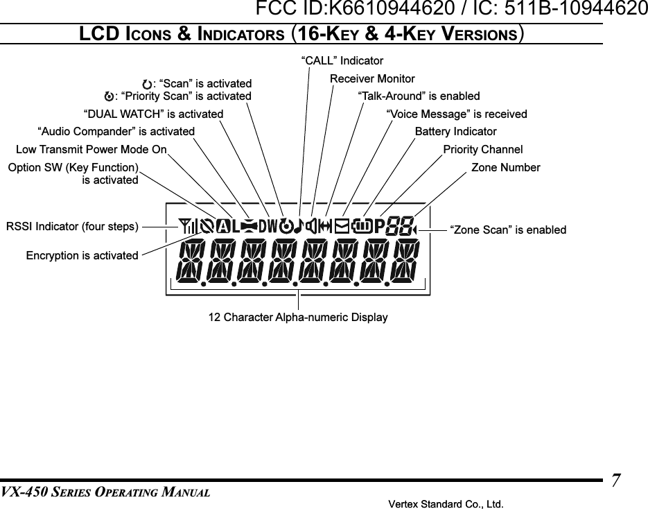
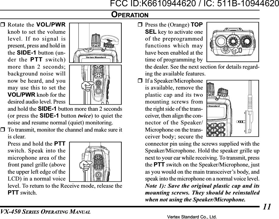
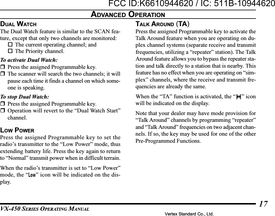
![VX-450 SERIES OPERATING MANUAL14ADVANCED OPERATIONProgrammable Key FunctionsAll versions of the VX-450 include the TOP SEL,SIDE-1, and SIDE-2 key. The 16-key and 4-key ver-sions include the [A], [B], [C], and [D] function keys.Furthermore, the 16-key version includes the [] and[#] function keys.The Programmable key functions can be customized,via programming by your Vertex Standard dealer, tomeet your communications/network requirements.Some features may require the purchase and instal-lation of optional internal accessories. The possibleProgrammable key programming features are illus-trated at the right, and their functions are explainedon page 16. For further details, contact your VertexStandard dealer.For future reference, check the box next to each func-tion that has been assigned to the Programmable keyon your particular radio, and keep it handy.TOP SELFUNCTIONNoneMonitorLampLock1ScanDual WatchLow PowerTalk AroundTX Save DisableEncryptionFM ScanZone Up1Zone Down1Channel Up1Channel Down1Set1Call/ResetSIDE-1 SIDE-2 [A] [B] [C] [D]PROGRAMMABLE KEY[] [#]Vertex Standard Co., Ltd.FCC ID:K6610944620 / IC: 511B-10944620Vertex Standard Co., Ltd.](https://usermanual.wiki/Yaesu-Musen/10944620/User-Guide-1406998-Page-16.png)
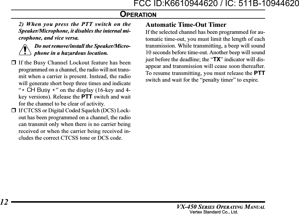
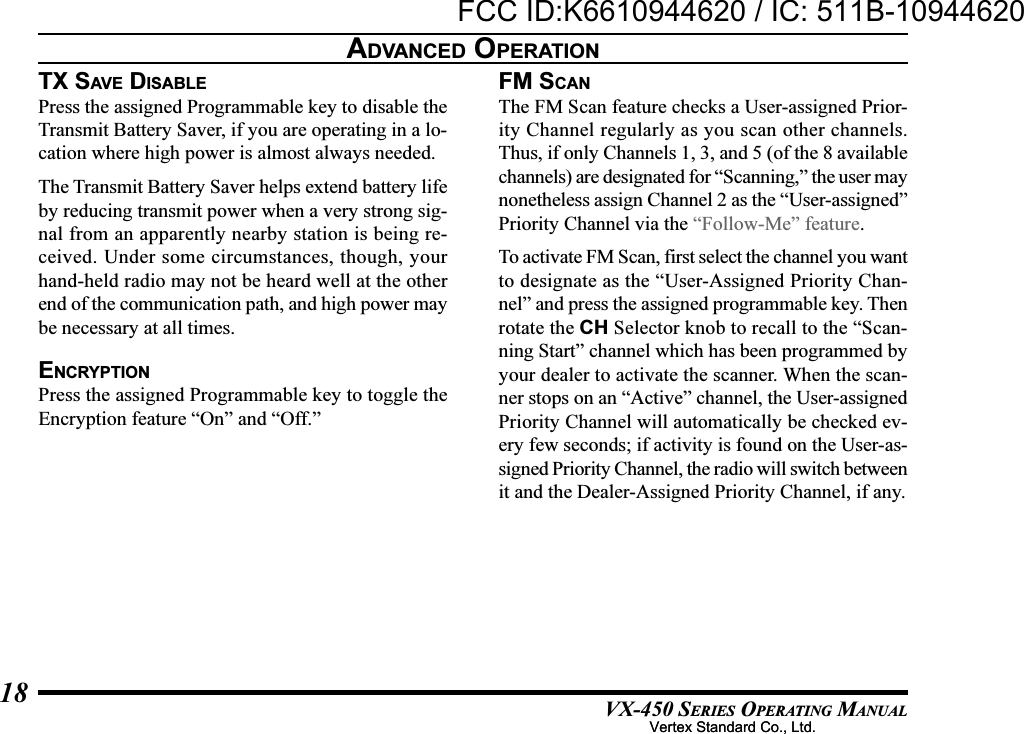
![VX-450 SERIES OPERATING MANUAL15ADVANCED OPERATIONFUNCTIONCall 1Call 2Call 3Call 4Call 5Code Up1Code Down1Code Set1Speed Dial2Option SW 1Option SW 2EmergencyPRI-11Selectable Tone1Direct Channel #11Direct Channel #21Direct Channel #31Direct Channel #41REC3PLAY3SQLAF Min VolumeStatus Set1Status Up1Status Down1Status CheckLone WorkerDTMF Code Set2TA ScanPriority DisableBeep OffWhisperDutyTOP SEL SIDE-1 SIDE-2 [B] [C] [D]PROGRAMMABLE KEY[A] [] [#]1: This function can not be selected on the Non-LCD Version2: This function is only selected on the 16-key Version3: Requires DVS-8 Voice Storage UnitVertex Standard Co., Ltd.FCC ID:K6610944620 / IC: 511B-10944620Vertex Standard Co., Ltd.](https://usermanual.wiki/Yaesu-Musen/10944620/User-Guide-1406998-Page-17.png)
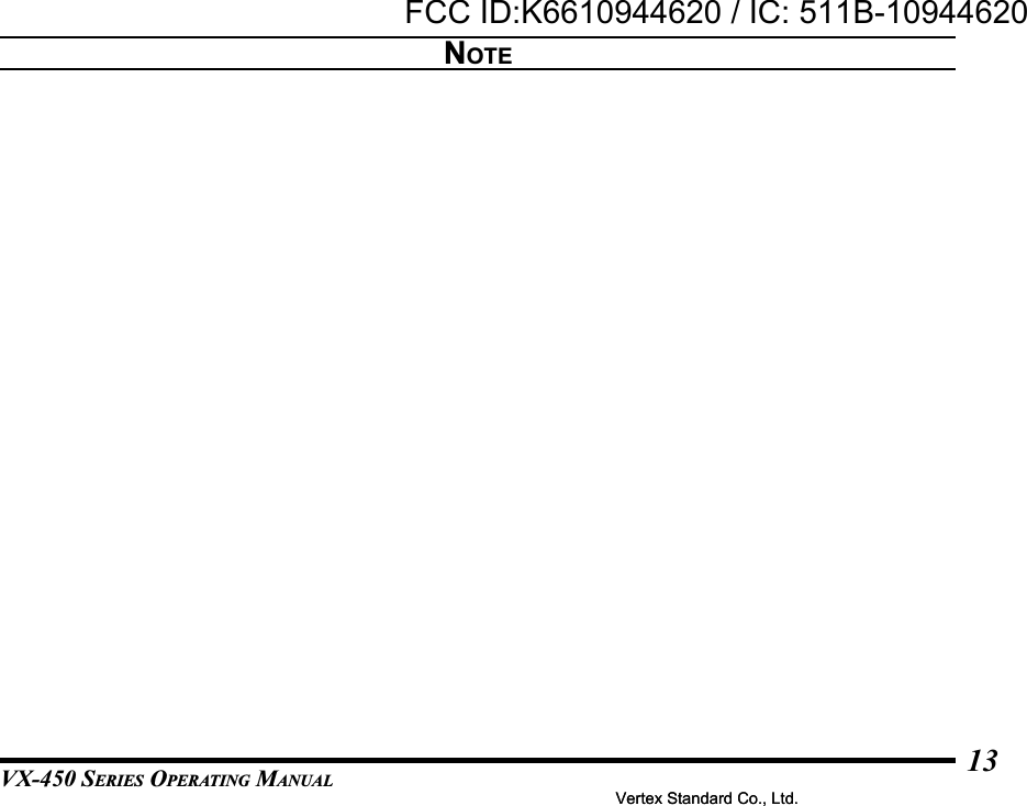
![VX-450 SERIES OPERATING MANUAL20CALL 1 TO CALL 5Press the assigned Programmable key to send a 2-tone/5-tone sequential tone group which is pre-de-fined.CODE UP/DOWNPress the assigned Programmable key to select a 2-tone/5-tone encode code from the pre-defined encodelist.CODE SETPress the assigned Programmable key to change theencode digits for 5-tone operation. To change a spe-cific digit, select the desired digit using the [A] key,then change the number using the [B]/[C] keys, andstore the number using the [D] key.SPEED DIAL (16-KEY VERSION ONLY)Your Dealer may have pre-programmed Auto-Dialtelephone number memories into your radio.To dial a number, press the assigned Programmablekey, then press the front panel’s numeric key corre-sponding to the Auto-Dial memory number list pro-vided by your Dealer or Network Administrator. TheDTMF tones sent during the dialing sequence willbe heard in the speaker.OPTION SW1Press the assigned Programmable key to toggle theoptional accessory “1” “On” and “Off.”OPTION SW2Press the assigned Programmable key to toggle theoptional accessory “2” “On” and “Off.”EMERGENCYThe VX-450 series include an “Emergency” featurewhich may be useful for alerting another party moni-toring on the same frequency as your transceiver’schannel.Press the assigned Programmable key to initiate anemergency call. For further details contact yourDealer.PRI-1Press the assigned Programmable key to recall thepre-defined Priority channel. When you recall thePriority channel, the “P” notation will appear on theLCD.ADVANCED OPERATIONVertex Standard Co., Ltd.FCC ID:K6610944620 / IC: 511B-10944620Vertex Standard Co., Ltd.](https://usermanual.wiki/Yaesu-Musen/10944620/User-Guide-1406998-Page-22.png)
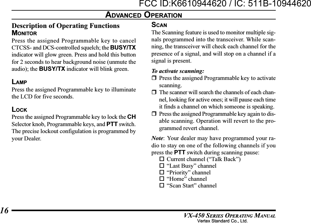
![VX-450 SERIES OPERATING MANUAL21ADVANCED OPERATIONSELECTABLE TONEPress the assigned Programmable key to select a sub-audible tone (CTCSS/DCS) from the pre-defined tonetable. You can operate using the indicated sub-au-dible tone in the Selectable Tone mode.DIRECT CH#1 TO #4Press the assigned Programmable key to recall theDealer pre-programmed channel directly.REC/PLAY (VOICE STORAGE: OPTION)This function allows your radio to record a receivedvoice message, and to play back the recorded audio.It requires installation of the optional Voice Record-ing Unit.Recording;Press the assigned Programmable key for 1.5 sec-onds to enable the Voice Recording Mode. If the in-coming signal is received, so as to un-mute thesquelch and pass audio, then the “ ” Icon will flashand received audio will be recorded. When the voicerecording is completed, the “ ” stays on.Playback;Press the assigned Programmable key momentarilyto play back the last message.To stop the play-back, press the TOP SEL key.While playback is proceeding, you may press the [A]key (4-key version) or [] key (16-key version) tojump to the previous message, or press the [B] key(4-key version) or [#] key (16-key version) to jumpto the next message. Furthermore, press the [D] keyto clear the all messages and stop the play-back.SQLYou can manually adjust the squelch level using thisfunction:Press the assigned Programmable key. A tone willsound, and the current squelch level will appearon the display.Press the SIDE-1/SIDE-2 button to select the de-sired squelch level.Two seconds after releasing the SIDE-1/SIDE-2button, the display will revert to the normal chan-nel indication.AF MIN VRPress the assigned Programmable key to reduce theaudio output to the (lower) level programmed by yourDealer.Vertex Standard Co., Ltd.FCC ID:K6610944620 / IC: 511B-10944620Vertex Standard Co., Ltd.](https://usermanual.wiki/Yaesu-Musen/10944620/User-Guide-1406998-Page-23.png)
![VX-450 SERIES OPERATING MANUAL22STATUS SETPress the assigned Programmable key to change the5-Tone status code. To change the status code, selectthe desired digit by [A] key, then change the numberby [B]/[C] key, and store the number by [D] key.STATUS UP/DOWNPress the assigned Programmable key to select a 5-Tone status code from the pre-defined status list.STATU S CHECKPress the assigned Programmable key to check the5-Tone receive status code. When you press this key,the LCD display will indicate the “Message” corre-sponding to the receive status condition per the pre-defined status list.LONE WORKERPress the assigned Programmable key to toggle theLone Worker feature “On” and “Off.”The Lone Worker feature is designed to emit an alarmfor 30 seconds when the Lone Worker Timer (pro-grammed by your Dealer) has expired. If the userdoes not reset the timer by pressing the PTT switch,the radio switches to the Emergency mode.DTMF CODE SET (16-KEY VERSION ONLY)You may send the desired telephone number manu-ally.To dial a number manually, press the assigned Pro-grammable key, then press the desired numbers onthe front panel’s numeric key. Now, press the PTTswitch to send the telephone number. The DTMFtones sent during the dialing sequence will be heardin the speaker.TA SCANPress the assigned Programmable key to toggle theTA (Talk Around) scan feature “On” and “Off.”While TA scan is proceeding, the VX-450 will searchboth the transmit and receive frequencies (the “ ”icon will blink). When a signal is encountered on thereceive frequency, the VX-450 will pause until thesignal disappears (“ ” icon will appear but notblink). When a signal is encountered on the transmitfrequency, the VX-450 will check for activity on thereceive frequency every few seconds (interval pro-grammed by your Dealer).ADVANCED OPERATIONVertex Standard Co., Ltd.FCC ID:K6610944620 / IC: 511B-10944620Vertex Standard Co., Ltd.](https://usermanual.wiki/Yaesu-Musen/10944620/User-Guide-1406998-Page-24.png)