Yaesu Musen 20165X40 SCANNING RECEIVER WITH AMATEUR TRANSMITTER User Manual OPERATING MANUAL
Yaesu Musen Co., Ltd. SCANNING RECEIVER WITH AMATEUR TRANSMITTER OPERATING MANUAL
UserManual.wiki
>
Yaesu Musen
>
20165X40 User Manual
OPERATING MANUAL
Navigation menu
Upload a User Manual
Namespaces
Wiki Guide
HTML
PDF
Info
Views
User Manual
Discussion / Help
Navigation
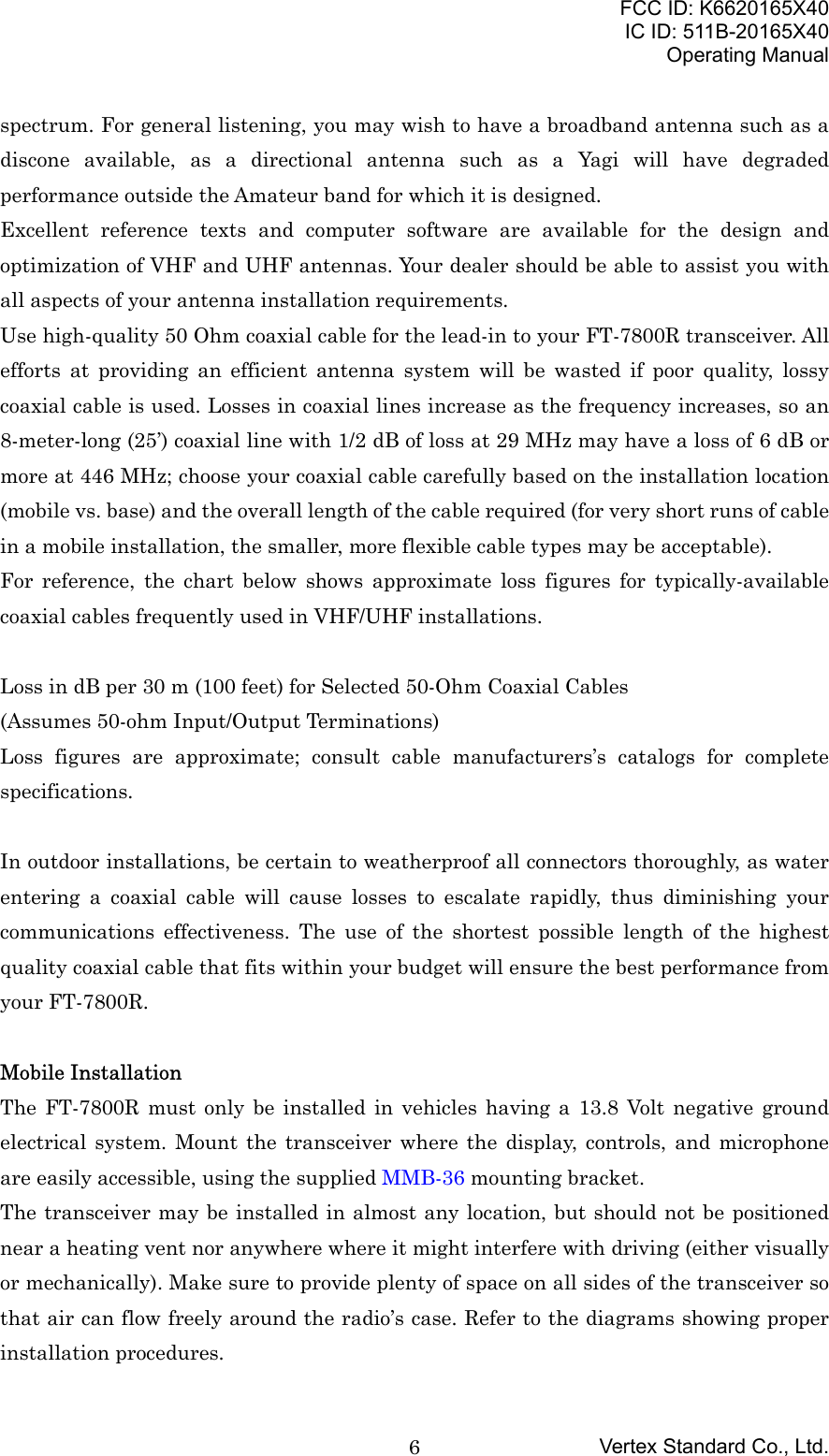
![FCC ID: K6620165X40IC ID: 511B-20165X40Operating ManualVertex Standard Co., Ltd.3Specifications are subject to change without notice, and are guaranteed within the 144and 430 MHz amateur bands only. Frequency ranges will vary according to transceiverversion; check with your dealer.Accessories & OptionsSupplied AccessoriesMicrophone MH-48A6J 1Mobile Mounting Bracket MMB-36 1DC Power Cord w/Fuse (T9021715) 1Spare Fuse 15 A (Q0000081) 2Operating Manual 1Warranty Card 1Optional AccessoriesMH-48A6J DTMF Microphone*1MH-42B6JS Hand Microphone*1YSK-7800 Separation KitMEK-2 Microphone Extension Kit*2MLS-100 High-Power External SpeakerFP-1023 AC Power Supply (25A: USA only)FP-1030A AC Power Supply (30A)CT-39A Packet Interface CableAvailability of accessories may vary. Some accessories are supplied as standard per localrequirements, while others may be unavailable in some regions. Consult your Yaesudealer for details regarding these and any newly-available options Connection of anynon-Yaesu-approved accessory, should it cause damage, may void the Limited Warrantyon this apparatus.*1: If you replace the microphone from the MH-48A6J to MH-42B6JS or vice versa,change the setting of Menu #22 (MIC). See page ?? for details.*2: When using the MH-48A6J or MH-42B6JS microphone in conjunction with theMEK-2, in some cases, the programmable key (MH-48: [P1] through [P4], MH-42: [ACC],[P], [P1], and [P2]) functions may operate erratically.](https://usermanual.wiki/Yaesu-Musen/20165X40/User-Guide-359544-Page-3.png)
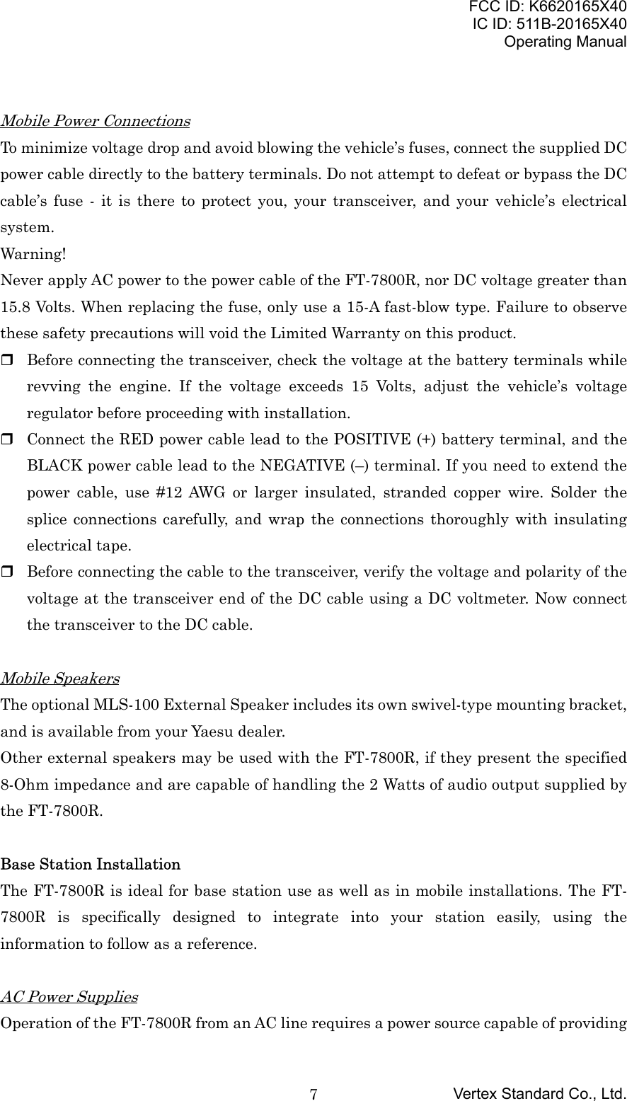
![FCC ID: K6620165X40IC ID: 511B-20165X40Operating ManualVertex Standard Co., Ltd.9Finally, note that the Menu (“Set”) mode allows you to set the Packet data rate (1200 or9600 bps) independently for each band. If you have trouble getting your FT-7800R torespond correctly during packet operation, check to be certain that you do not haveMenu #26 (PKT.SPD) set to the wrong data rate.You may activate the microphone input while operating on the packet mode via theMenu #25 (PKT.MIC), if you desired.Front Panel Controls & Switches1. VOL KnobThis control adjusts the volume level of the receiver’s audio. Clockwise rotationincreases the audio level.2. SQL KnobThis control sets the threshold level at which received signals (or noise) will openthe squelch. It should be advanced clockwise just to the point where the noise issilenced (and the “BUSY” indicator on the display turns off), so as to provide thebest sensitivity to weak signals.3. Hyper Memory Buttons ([1] ~ [5])Press and hold in one of these buttons for 2 seconds to store the current totalconfiguration of the radio into a special “Hyper” memory bank.Press the appropriate button momentarily to recall the desired “Hyper” memory.4. [MHz(PRI)] KeyPress this key momentarily to allow tuning in 1-MHz steps on the VFO frequencywhile operating on the VFO mode. In the Memory mode, press this keymomentarily to allow tuning in 10 channel steps on the memory channels.Press and hold in this key for 1/2 second to activate the Priority Channel Scanning(Dual Watch feature).4. [TONE(HM/RV)] KeyPress this key momentarily to change the Tone Squelch mode: ENC (CTCSSEncoder), ENC.DEC (CTCSS Tone Squelch), or DCS (DCS) operation.Press and hold in this key for 1/2 second to reverse the transmit and receivefrequencies during split-frequency (i.e. “Repeater”) operation.](https://usermanual.wiki/Yaesu-Musen/20165X40/User-Guide-359544-Page-9.png)
![FCC ID: K6620165X40IC ID: 511B-20165X40Operating ManualVertex Standard Co., Ltd.105. [LOW(ACC)] KeyPress this key momentarily to select the transmitter power output level (“LOW,”“MID2,” “MID1,” or “HIGH”).Press and hold in this key for 1/2 second to recall the Weather Broadcast Channels.You can program the alternate (press and hold in) function of this key to otherfunctions, if desired. See page ?? for details.6. [BAND(SET)] KeyWhile operating on the VFO mode, press this key momentarily to toggle theoperating band as follows:144 MHz Æ 250 MHz Æ 350 MHz Æ 430 MHz Æ 850 MHz Æ 144 MHz ......In the Memory mode, press this key momentarily to activate the “Memory Tune”function.Press and hold in this key for 1/2 second to enter the Set (“Menu”) mode.7. [V/M(MW)] KeyPress this key momentarily to switch the frequency control among the VFO,Memory System, and Home channel.Press and hold in this key for 1/2 second to transfer the VFO contents into aMemory register.8. [SCN(SEL)] KeyPress this key momentarily to activate the Scanner.Press and hold in this key for 1/2 second to select the scan mode.9. [S.SCH(ARTS)] KeysPress this key momentarily to activate the Smart Search feature.Press and hold in this key for 1/2 second to activate the ARTS feature.10. DIAL knobThis 20-position detented rotary switch is the tuning dial for the transceiver. It isused for most tuning, memory selection, and function setting tasks on thetransceiver.11. PWR Switch](https://usermanual.wiki/Yaesu-Musen/20165X40/User-Guide-359544-Page-10.png)
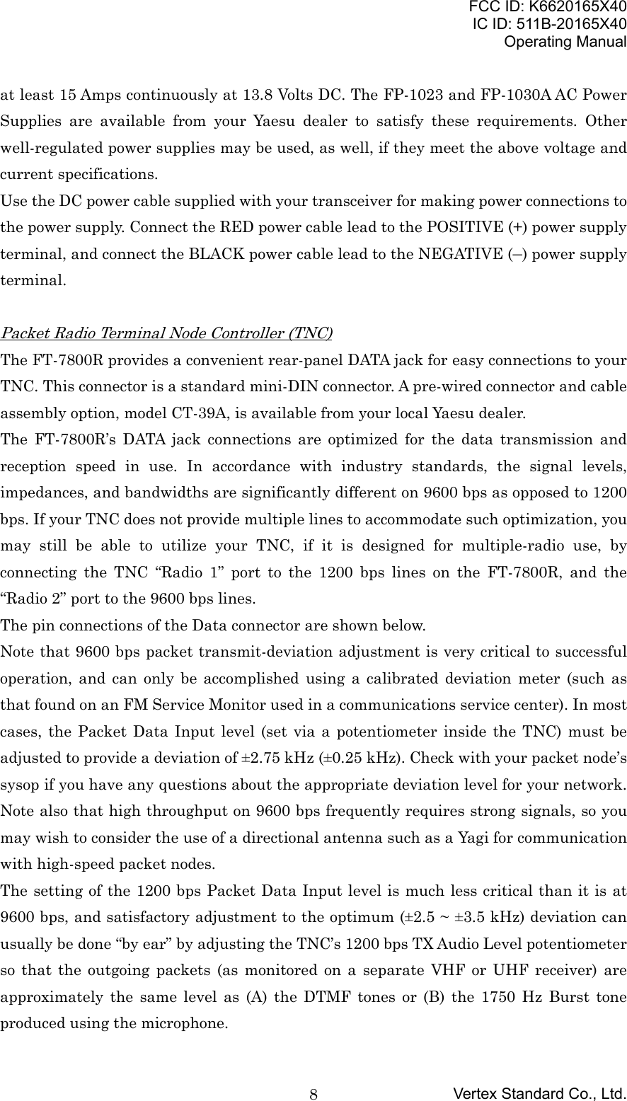
![FCC ID: K6620165X40IC ID: 511B-20165X40Operating ManualVertex Standard Co., Ltd.11Press and hold in this switch for 1/2 second to toggle the transceiver’s power on andoff.12. [%] KeyPress this key momentarily to activate the Internet Connection Feature.Press and hold in this key for 1/2 second to indicate the supply voltage for 2seconds.Side Panel Connection & Knob1. MIC Jack (Right Side)Connect the supplied microphone to this jack.2. Front Panel Release Knob (Left Side)Press this knob to unlock the front panel to detachable the front panel from thetransceiver’s main body for the separate operation (requires optional YSK-7800separate kit).Rear Panel Connections4. Antenna JackConnect your antenna here, using a type-M (PL-259) plug and coaxial cable.5. Cooling FanRotate this cooling fan while the radio is occurred transmission and after 30seconds when the radio is returning the receive mode from transmit mode.When the RF power amplifier heatsink reaches high temperature, this cooling fanrotate automatically even if the receive mode.6. DATA JackThis 6-pin mini-DIN connector provides simple interfacing to a packet TerminalNode Controller (TNC) for 1200 bps or 9600 bps operation. The pin connections areshown on page ??.7. EXT SP JackThis 2-conductor, 3.5-mm mini phone jack provides audio output for an optional](https://usermanual.wiki/Yaesu-Musen/20165X40/User-Guide-359544-Page-11.png)
![FCC ID: K6620165X40IC ID: 511B-20165X40Operating ManualVertex Standard Co., Ltd.12speaker. The optimum load impedance is 8 Ohms. Inserting a plug into this jackdisables the audio path to the transceiver’s internal speaker.8. 13.8V DC Cable Pigtails w/FuseThis is the DC power supply connection for the transceiver. Use the supplied DCcable to connect this pigtail to the car battery or base station DC power supplycapable of at least 9 Amperes (continuous duty). Make certain that the Red leadconnects to the Positive (+) side of the power source, and that the Black leadconnects to the Negative (–) side of the power source.MH-48A6J Microphone1. PTT SwitchPress this switch to transmit, and release it to receive.2. KeypadThese 16 keys generate DTMF tones during transmission.In the receive mode, the numeric (0 - 9) keys can be used for direct frequency entryand/or direct numeric recall of the Memory channels and the alphabet (A - D) keyscan be used for controls the transceiver, as follow:Key FunctionA Activate the Smart Search feature.B Switch the Memory Channel display between the “Frequency” format and“Alpha-numeric Tag” format.C Disable the noise squelch action, allowing you to hear very weak signalsnear the background noise level.D Allow tuning in 1-MHz steps on the VFO frequency while operating onthe VFO mode. In the Memory mode, allow tuning in 10 channel steps onthe memory channels.3. [P1]/[P2]/[P3]/[P4] Buttons[P1] button:This button replicate the functions of the front panel [BAND(SET)] key.While operating on the VFO mode, press this button momentarily to toggle theoperating band as follows:144 MHz Æ 250 MHz Æ 350 MHz Æ 430 MHz Æ 850 MHz Æ 144 MHz ......In the Memory mode, press this button momentarily to activate the “Memory Tune”function.](https://usermanual.wiki/Yaesu-Musen/20165X40/User-Guide-359544-Page-12.png)
![FCC ID: K6620165X40IC ID: 511B-20165X40Operating ManualVertex Standard Co., Ltd.13Press and hold in this key for 1/2 second to enter the Set (“Menu”) mode.[P2] button:This button replicate the functions of the front panel [V/M(MW)] key.Press this button momentarily to switch the frequency control among the VFO,Memory System, and Home channel.Press and hold in this button for 1/2 second to transfer the VFO contents into aMemory register.[P3] button:This button replicate the functions of the front panel [TONE(REV)] key.Press this button momentarily to change the Tone Squelch mode: ENC (CTCSSEncoder), ENC.DEC (CTCSS Tone Squelch), or DCS (DCS) operation.Press and hold in this key for 1/2 second to reverse the transmit and receivefrequencies during split-frequency (i.e. “Repeater”) operation.[P4] button:This button replicate the functions of the front panel [LOW(ACC)] key.Press this button momentarily to select the transmitter power output level (“LOW,”“MID2,” MID1,” or “HIGH”).Press and hold in this key for 1/2 second to recall the Weather Broadcast Channels.You can program the [P1], [P2], [P3], and [P4] buttons for other functions, if desired.See page ?? for details.4. LAMP SwitchThis switch illuminates the Microphone keypad.5. LOCK SwitchThis switch locks out the Microphone buttons (except for the keypad and PTTswitch).6. [UP]/[DWN] ButtonPress (or hold in) either of these buttons to tune (or scan up or down) the operatingfrequency or through the memory channels. In many ways, these buttons emulatethe function of the (rotary) DIAL knob.](https://usermanual.wiki/Yaesu-Musen/20165X40/User-Guide-359544-Page-13.png)
![FCC ID: K6620165X40IC ID: 511B-20165X40Operating ManualVertex Standard Co., Ltd.14MH-42B6JS MicrophoneThe optional MH-42B6JS is similar to the MH-48A6J, but the MH-42B6JS does notinclude a DTMF keypad and its illumination switch.1. PTT SwitchPress this switch to transmit, and release it to receive.2. [ACC]/[P]/[P1]/[P2] Buttons[ACC] button:This button replicate the functions of the front panel [BAND(SET)] key.While operating on the VFO mode, press this button momentarily to toggle theoperating band as follows:144 MHz Æ 250 MHz Æ 350 MHz Æ 430 MHz Æ 850 MHz Æ 144 MHz ......In the Memory mode, press this button momentarily to activate the “Memory Tune”function.Press and hold in this key for 1/2 second to enter the Set (“Menu”) mode.[P] button:This button replicate the functions of the front panel [V/M(MW)] key.Press this button momentarily to switch the frequency control among the VFO,Memory System, and Home channel.Press and hold in this button for 1/2 second to transfer the VFO contents into aMemory register.[P1] button:This button replicate the functions of the front panel [TONE(REV)] key.Press this button momentarily to change the Tone Squelch mode: ENC (CTCSSEncoder), ENC.DEC (CTCSS Tone Squelch), or DCS (DCS) operation.Press and hold in this key for 1/2 second to reverse the transmit and receivefrequencies during split-frequency (i.e. “Repeater”) operation.[P2] button:This button replicate the functions of the front panel [LOW(ACC)] key.Press this button momentarily to select the transmitter power output level (“LOW,”](https://usermanual.wiki/Yaesu-Musen/20165X40/User-Guide-359544-Page-14.png)
![FCC ID: K6620165X40IC ID: 511B-20165X40Operating ManualVertex Standard Co., Ltd.15“MID2,” MID1,” or “HIGH”).Press and hold in this key for 1/2 second to recall the Weather Broadcast Channels.You can program the [ACC], [P], [P1], and [P2] buttons for other functions, ifdesired. See page ?? for details.3. LOCK SwitchThis switch locks out the Microphone buttons (except for the keypad and PTTswitch).4. [UP]/[DWN] ButtonPress (or hold in) either of these buttons to tune (or scan up or down) the operatingfrequency or through the memory channels. In many ways, these buttons emulatethe function of the (rotary) DIAL knob.Basic OperationHi! I’m R. F. Radio, and I’ll be helping you along as you learn the many features of theFT-7800R. I know you’re anxious to get on the air, but I encourage you to read the“Operation” section of this manual as thoroughly as possible, so you’ll get the most outof this fantastic new transceiver. Now. . .let’s get operating!Turning the Transceiver On and Off1. To turn the transceiver on, press and hold in the PWR switch for 1/2 second.When you turn on the FT-7800R, the current DC supply voltage is indicated on theLCD for 2 seconds. After this interval, the display will switch its normal indicationof the operating frequency.2. To turn the transceiver off, again press and hold in the PWR switch for 1/2 second.Adjusting the Audio Volume Level and Squelch SettingAt first, set the SQL knob fully counter-clockwise. Now, you may rotate the VOL knobclockwise to adjust the receiver volume for a comfortable listening level, using thebackground noise as a reference.To set the squelch, turn the SQL knob clockwise a slightly past the point where thebackground noise is muted. This is the point of best sensitivity to weak signals, and werecommend that you not rotate the SQL knob very much past the point where the](https://usermanual.wiki/Yaesu-Musen/20165X40/User-Guide-359544-Page-15.png)
![FCC ID: K6620165X40IC ID: 511B-20165X40Operating ManualVertex Standard Co., Ltd.16background noise is just silenced.A special “RF Squelch” feature is provided on this radio. This feature allows you to setthe squelch so that only signals exceeding a certain S-meter level will open the squelch.See page ?? for detailsSelecting the Operating BandPress the [BAND(SET)] key to move the operating band:144 MHz Æ 250 MHz Æ 350 MHz Æ 430 MHz Æ 850 MHz Æ 144 MHz ......R.F. Says: You may select the operating band by pressing the microphone’s [P1] key.Frequency Navigation1) Tuning DialRotating the DIAL knob allows tuning in the pre-programmed steps established for theVFO frequency. Clockwise rotation of the DIAL knob causes the FT-7800R to be tunedtoward a higher frequency, while counter-clockwise rotation will lower the operatingfrequency.Press the [MHz(PRI)] key momentarily, then rotate the DIAL knob, to change thefrequency steps to 1 MHz per step. This feature is extremely useful for making rapidfrequency excursions over the wide tuning range of the FT-7800R.2) Direct Keypad Frequency Entry (MH-48A6J Microphone)The keypad of the MH-48A6J DTMF Microphone may be used for direct entry of theoperating frequency.To enter a frequency from the MH-48A6J keypad, just press the numbered digits in theproper sequence. There is no “Decimal point” key on the MH-48A6J keypad.Examples: To enter 146.480 MHz, press [1] Æ [4] Æ [6] Æ [4] Æ [8] Æ [0]To enter 433.000 MHz, press [4] Æ [3] Æ [3] Æ [0] Æ [0] Æ [0]3) ScanningFrom the VFO mode, press and hold the [SCAN(SEL)] key for 1/2 second, then rotatethe DIAL knob to select the bandwidth for the VFO scanner. Now, press the[SCAN(SEL)] key momentarily to initiate scanning toward a higher frequency. The FT-7800R will stop when it receives a signal strong enough to break through the squelchthreshold. The FT-7800R will then hold on that frequency according to the setting of the“Resume” mode (Menu #36 (SCAN); see page ??). See page ?? for details regarding theVFO Scan operation.](https://usermanual.wiki/Yaesu-Musen/20165X40/User-Guide-359544-Page-16.png)
![FCC ID: K6620165X40IC ID: 511B-20165X40Operating ManualVertex Standard Co., Ltd.17If you wish to reverse the direction of the scan (i.e. toward a lower frequency, instead ofa higher frequency), just rotate the DIAL knob one click in the counter-clockwisedirection while the FT-7800R is scanning. The scanning direction will be reversed. Torevert to scanning toward a higher frequency once more, rotate the DIAL knob one clickclockwise.Press the [SCAN(SEL)] key again to cancel scanning.R.F. Says: You may also initiate the scanner by pressing and holding in themicrophone’s [UP] or [DWN] key. However, in this case, the scanner cause to sweepfrequencies only on the current band. If you would like the scanner not to be restrictedto the current band, you may change Menu #46 (VFO.BND) to allow the scanner to hopto the low edge of the next-highest band when the VFO frequency reaches the high endof the current band (or vice- versa). See page ?? for details.TransmissionTo transmit, simply close the PTT (Push To Talk) switch on the microphone when thefrequency is clear. Hold the microphone approximately 25 mm (1”) from your mouth,and speak into the microphone in a normal voice level. When your transmission iscomplete, release the PTT switch: the transceiver will revert to the receive mode.R.F. Says: When the RF power amplifier heatsink is reached to a factory presettemperature, reduce the transmit power level to the “LOW” automatically to preventthe over heating the radio. You leave transmit in this condition (“LOW” mode), the radioreturn to the receive mode forcibly.Changing the Transmitter Power LevelYou can select from among a total of four transmit power levels on your FT-7800R.To change the power level, press the [LOW(ACC)] key to select one of four powersettings. These power levels will be stored, in memory registers, at the time of memorystorage (see page ?? for details on Memory operation).During transmission, the Bar Graph will deflect in the display, according to the poweroutput selected.Advanced OperationLock FeatureIn order to prevent accidental frequency change or inadvertent transmission, variousaspects of the FT-7800R’s keys may be locked out. The possible lockout combinations](https://usermanual.wiki/Yaesu-Musen/20165X40/User-Guide-359544-Page-17.png)
![FCC ID: K6620165X40IC ID: 511B-20165X40Operating ManualVertex Standard Co., Ltd.18are:KEY: Just the front panel keys are locked outDIAL: Just the front panel DIAL is locked outKY+DL: Both the DIAL and Keys are locked outPTT: The PTT switch is locked (TX not possible)KY+PTT: Both the keys and PTT switch are locked outDL+PTT: Both the DIAL and PTT switch are locked outALL: All of the above are locked outTo lock out some or all of the keys:1. Press and hold in the [BAND(SET)] key for 1/2 second to enter the Set mode.2. Rotate the DIAL knob to select Menu #21 (LOCK).3. Press the [BAND(SET)] key momentarily, then rotate the DIAL knob to choosebetween one of the locking schemes as outline above.4. When you have made your selection, press the [BAND(SET)] key momentarily tosave the new setting, then press and hold in the [BAND(SET)] key for 1/2 second toexit to normal operation.5. To unlock the panel switches and DIAL knobs, select “OFF” in step 3 above.Keyboard BeeperA key/button beeper provides useful audible feedback whenever a key/button is pressed.If you want to turn the beep off:1. Press and hold in the [BAND(SET)] key for 1/2 second to enter the Set mode.2. Rotate the DIAL knob to select Menu #5 (KEY.BEP).3. Press the [BAND(SET)] key momentarily, then rotate the DIAL knob to change thesetting to “OFF.”4. Press the [BAND(SET)] key momentarily to save the new setting, then press andhold in the [BAND(SET)] key for 1/2 second to exit to normal operation.5. To back on again the beep, select “ON” in step 3 above.Display BrightnessThe FT-7800R display illumination has been specially engineered to provide highvisibility with minimal disruption of your “Night vision” while you are driving. Thebrightness of the display is manually adjustable, using following procedure:1. Press and hold in the [BAND(SET)] key for 1/2 second to enter the Set mode.2. Rotate the DIAL knob to select Menu #11 (DIMMER).](https://usermanual.wiki/Yaesu-Musen/20165X40/User-Guide-359544-Page-18.png)
![FCC ID: K6620165X40IC ID: 511B-20165X40Operating ManualVertex Standard Co., Ltd.193. Press the [BAND(SET)] momentarily, then rotate the DIAL knob to select acomfortable brightness level: DIM 1, DIM 2, DIM 3, or DIM.OFF (no illumination).4. Press the [BAND(SET)] key momentarily to save the new setting, then press andhold in the [BAND(SET)] key for 1/2 second to exit to normal operation.RF SquelchA special “RF Squelch” feature is provided on this radio. This feature allows you to setthe squelch so that only signals exceeding a certain S-meter level will open the squelch.To set up the RF Squelch circuit for operation, use the following procedure:1. Press and hold in the [BAND(SET)] key for 1/2 second to enter the Set mode.2. Rotate the DIAL knob to select Menu #32 (RF SQL).3. Press the [BAND(SET)] key momentarily, then rotate the DIAL knob to select thedesired signal strength level for the squelch threshold (OFF, S-2, S-3, S-4, S-5, S-6,S-7, S-8, S-9, or S-FULL).4. Press the [BAND(SET)] key momentarily to save the new setting, then press andhold in the [BAND(SET)] key for 1/2 second to exit to normal operation.5. Finally, rotate the SQL knob fully clockwise.Channel Step SelectionThe FT-7800R’s synthesizer provides the option of utilizing channel steps of5/10/12.5/15/20/25/50/100 kHz per step, as well as an automatic step selection based onthe current operating frequency (“AUTO”), any number of which may be important toyour operating requirements. The FT-7800R is set up at the factory in the “AUTO”configuration, which probably is satisfactory for most operation. However, if you need tochange the channel step increments, the procedure to do so is very easy; remember toget set up on the desired band before making any changes, as different steps may beprogrammed for each operating band.1. Press and hold in the [BAND(SET)] key for 1/2 second to enter the Set mode.2. Rotate the DIAL knob to select Menu #42 (STEP).3. Press the [BAND(SET)] momentarily, then rotate the DIAL knob to select the newchannel step size.4. Press the [BAND(SET)] key momentarily to save the new setting, then press andhold in the [BAND(SET)] key for 1/2 second to exit to normal operation.Receiving Mode SelectionThe FT-7800R provides for automatic mode changing when the radio is tuned to](https://usermanual.wiki/Yaesu-Musen/20165X40/User-Guide-359544-Page-19.png)
![FCC ID: K6620165X40IC ID: 511B-20165X40Operating ManualVertex Standard Co., Ltd.20different operating frequencies. However, should an unusual receiving situation arise inwhich you need to change to other receiving mode, the procedure to do so is very easy.1. Press and hold in the [BAND(SET)] key for 1/2 second to enter the Set mode.2. Rotate the DIAL knob to select Menu #35 (RX MOD).3. Press the [BAND(SET)] momentarily, then rotate the DIAL knob to select thedesired receiving mode.AUTO: Automatic mode setting per default values for the selected frequency rangeFM: Frequency Modulation (Narrow FM)AM: Amplitude Modulation4. Press the [BAND(SET)] key momentarily to save the new setting, then press andhold in the [BAND(SET)] key for 1/2 second to exit to normal operation.R.F. Says: Unless you have a compelling reason to do so, leave the Automatic ModeSelection feature on so as to save time and trouble when changing bands. If you make amode change for a particular channel or station, you can always store that one channelinto memory, as the mode setting will be memorized along with the frequencyinformation.Repeater OperationRepeater stations, usually located on mountaintops or other high locations, provide adramatic extension of the communication range for low-powered hand-held or mobiletransceivers. The FT-7800R includes a number of features which make repeateroperation simple and enjoyable.Repeater ShiftsYour FT-7800R has been configured, at the factory, for the repeater shifts customary inyour country. While the 144 MHz shift will be 600 kHz; on 70 cm, the shift may be 1.6MHz or 7.6 MHz.Depending on the part of the band in which you are operating, the repeater shift may beeither downward (–) or upward (+), and one of these icons will appear at the top of theLCD when repeater shifts have been enabled.Automatic Repeater Shift (ARS)The FT-7800R provides a convenient Automatic Repeater Shift feature, which causesthe appropriate repeater shift to be automatically applied whenever you tune into thedesignated repeater sub-bands in your country. These sub-bands are shown below.](https://usermanual.wiki/Yaesu-Musen/20165X40/User-Guide-359544-Page-20.png)
![FCC ID: K6620165X40IC ID: 511B-20165X40Operating ManualVertex Standard Co., Ltd.21If the ARS feature does not appear to be working, you may have accidentally disabled it.To re-enable ARS:1. Press and hold in the [BAND(SET)] key for 1/2 second to enter the Set mode.2. Rotate the DIAL knob to select Menu #4 (ARS).3. Press the [BAND(SET)] momentarily, then rotate the DIAL knob to change thesetting to “ON” (to enable Automatic Repeater Shift).4. Press the [BAND(SET)] key momentarily to save the new setting, then press andhold in the [BAND(SET)] key for 1/2 second to exit to normal operation.With repeater shift activated, you can temporarily reverse the transmit and receivefrequencies by pressing and holding in the [TONE(HM/RV)] key for 1/2 second. Use thisfeature to display the transmit frequency without transmitting, and to check thestrength of signals on a repeater uplink frequency (so as to determine whether of not aparticular station is within “Simplex” range, for example).Manual Repeater Shift ActivationIf the ARS feature has been disabled, or if you need to set a repeater shift directionother than that established by the ARS, you may set the direction of the repeater shiftmanually.To do this:1. Press and hold in the [BAND(SET)] key for 1/2 second to enter the Set mode.2. Rotate the DIAL knob to select Menu #33 (RPT.MOD).3. Press the [BAND(SET)] key momentarily, then rotate the DIAL knob to select thedesired shift among “RPT.–,” “RPT.+,” and “RPT.OFF.”4. Press the [BAND(SET)] key momentarily to save the new setting, then press andhold in the [BAND(SET)] key for 1/2 second to exit to normal operation.Changing the Default Repeater ShiftsIf you travel to a different region, you may need to change the default repeater shift soas to ensure compatibility with local operating requirements.To do this, follow the procedure below:1. Press and hold in the [BAND(SET)] key for 1/2 second to enter the Set mode.2. Rotate the DIAL knob to select Menu #39 (SHIFT).3. Press the [BAND(SET)] key momentarily, then rotate the DIAL knob to select thenew repeater shift magnitude.4. Press the [BAND(SET)] key momentarily to save the new setting, then press andhold in the [BAND(SET)] key for 1/2 second to exit to normal operation.](https://usermanual.wiki/Yaesu-Musen/20165X40/User-Guide-359544-Page-21.png)
![FCC ID: K6620165X40IC ID: 511B-20165X40Operating ManualVertex Standard Co., Ltd.22R.F. Says: If you just have one “odd” split that you need to program, don’t change the“default” repeated shifts using this Menu Item! Enter the transmit and receivefrequencies separately, as shown on page ??.CTCSS/DCS OperationCTCSS OperationMany repeater systems require that a very-low-frequency audio tone be superimposedon your FM carrier in order to activate the repeater. This helps prevent false activationof the repeater by radar or spurious signals from other transmitters. This tone system,called “CTCSS” (Continuous Tone Coded Squelch System), is included in your FT-7800R,and is very easy to activate.R.F. Says: CTCSS setup involves two actions: setting the Tone Mode and then setting ofthe Tone Frequency. These actions are set up by using the [TONE(REV)] key and Setmode #44 (TN FRQ).1. Press the [TONE(REV)] key several times, so that “ENC” appears on the display;this activates the CTCSS Encoder, which allows repeater access.R.F. Says: 1) You may notice an additional “DCS” icon appearing while you pressthe [TONE(REV)] key in this step. We’ll discuss the Digital Code Squelch systemshortly.2) You may notice “REV TN” indication on the display, this means that the ReverseTone Squelch system is active, which mutes your FT-7800R’s receiver when itreceives a call from the radio sending a matched CTCSS tone. The “DEC” icon willblink on the display when the Reverse Tone Squelch system is activated.2. Press the [TONE(REV)] key once more in above step will cause “ENC DEC” toappear. When “ENC DEC” appears, this means that the Tone Squelch system isactive, which mutes your FT-7800R’s receiver until it receives a call from anotherradio sending out a matching CTCSS tone. This can help keep your radio quietuntil a specific call is received, which may be helpful while operating in congestedareas.3. When you have made your selection of the CTCSS tone mode, press and hold in the[BAND(SET)] key for 1/2 second to enter the Set mode, then rotate the DIAL knobto select Menu #44 (TN FRQ). This Menu selection allows setting of the CTCSStone frequency to be used.4. Press the [BAND(SET)] key momentarily to enable adjustment of the CTCSSfrequency.](https://usermanual.wiki/Yaesu-Musen/20165X40/User-Guide-359544-Page-22.png)
![FCC ID: K6620165X40IC ID: 511B-20165X40Operating ManualVertex Standard Co., Ltd.235. Rotate the DIAL knob until the display indicates the Tone Frequency you need to beusing.6. When you have made your selection, press the [BAND(SET)] key momentarily tosave the new setting, then press and hold in the [BAND(SET)] key for 1/2 second toexit to normal operation.R.F. Says: Your repeater may or may not re-transmit a CTCSS tone - some systems justuse CTCSS to control access to the repeater, but don’t pass it along when transmitting.If the S-Meter deflects, but the FT-7800R is not passing audio, press the [TONE(REV)]key so that “ENC” appears - this will allow you to hear all traffic on the channel beingreceived.DCS OperationAnother form of tone access control is Digital Code Squelch, or DCS. It is a newer, moreadvanced tone system which generally provides more immunity from false paging thandoes CTCSS. The DCS Encoder/Decoder is built into your FT-7800R, and operation isvery similar to that just described for CTCSS. Your repeater system may be configuredfor DCS; if not, it is frequently quite useful in Simplex operation if your friend(s) usetransceivers equipped with this advanced feature.R.F. Says: Just as in CTCSS operation, DCS requires that you set the Tone Mode to DCSand that you select a Tone Code.1. Press the [TONE(REV)] key until “DCS” appears on the display; this activates theDCS Encoder/Decoder.2. Now, press and hold in the [BAND(SET)] key for 1/2 second to enter the Set mode,then rotate the DIAL knob to select Menu #9 (DCS.COD).3. Press the [BAND(SET)] key momentarily to enable the adjustment of the DCS code.4. Rotate the DIAL knob to select the desired DCS Code (a three-digit number).5. When you have made your selection, press the [BAND(SET)] key momentarily tosave the new setting, then press and hold in the [BAND(SET)] key for 1/2 second toexit to normal operation.R.F. Says: Remember that the DCS is an Encode/Decode system, so your receiver willremain muted until a matching DCS code is received on an incoming transmission.Switch the DCS off when you’re just tuning around the band!Tone Search ScanningIn operating situations where you don’t know the CTCSS or DCS tone being used byanother station or stations, you can command the radio to listen to the incoming signal](https://usermanual.wiki/Yaesu-Musen/20165X40/User-Guide-359544-Page-23.png)
![FCC ID: K6620165X40IC ID: 511B-20165X40Operating ManualVertex Standard Co., Ltd.24and scan in search of the tone being used. Two things must be remembered in thisregard: You must be sure that your repeater uses the same tone type (CTCSS vs. DCS). Some repeaters do not pass the CTCSS tone; you may have to listen to the station(s)transmitting on the repeater uplink (input) frequency in order to allow Tone SearchScanning to work.To scan for the tone in use:1. Set the radio up for either CTCSS or DCS Decoder operation (see the previousdiscussion). In the case of CTCSS, “ENC DEC” will appear on the display; in thecase of DCS, “DCS” will appear on the display.2. Press and hold in the [BAND(SET)] key for 1/2 second to enter the Set mode.3. Rotate the DIAL knob to select Menu #44 (TN FRQ) when CTCSS is selected, orMenu #9 (DCS.COD) during DCS operation.4. Press the [BAND(SET)] key to enable adjustment of the selected Menu Item.5. Press the [SCAN(SEL)] key momentarily to start scanning for the incoming CTCSSor DCS tone/code.6. When the radio detects the correct tone or code, it will halt on that tone/code, andaudio will be allowed to pass. Press the [BAND(SET)] key momentarily to lock inthat tone/code, then press and hold in the [BAND(SET)] key for 1/2 second to savethe new setting and exit to normal operation.R.F. Says: If the Tone Scan feature does not detect a tone or code, it will continue to scanindefinitely. When this happens, it may be that the other station is not sending any tone.You can press the [SCAN(SEL)] key to halt the scan at any time.Tone Scanning works either in the VFO or Memory modes.Split Tone OperationThe FT-7800R can be operated in a Split Tone configuration via the Set mode.1. Press and hold in the [BAND(SET)] key for 1/2 second to enter the Set mode.2. Rotate the DIAL knob to select Menu #41 (SPLIT).3. Press the [BAND(SET)] key momentarily, then rotate the DIAL knob to select ON(to enable the Split Tone feature).4. Press the [BAND(SET)] key momentarily to save the new setting, then press andhold in the [BAND(SET)] key for 1/2 second to exit to normal operation.When the Split Tone feature is activated, you can see the following additionalparameters after the “DCS” parameter while selecting the Tone Mode by pressing the[TONE(REV)] key:](https://usermanual.wiki/Yaesu-Musen/20165X40/User-Guide-359544-Page-24.png)
![FCC ID: K6620165X40IC ID: 511B-20165X40Operating ManualVertex Standard Co., Ltd.25D: DCS Encode only(the “DCS” icon will blink during operation)ENC DCS: Encodes a CTCSS Tone and Decodes a DCS code(the “DCS” and “ENC” icons will appear during operation)D-DEC: Encodes a DCS code and Decodes a CTCSS Tone(the “DCS” icon will blink and the “DEC” icon will appear during operation)Select the desired operating mode, from the selections shown above.Memory OperationThe FT-7800R provides a wide variety of memory system resources. These include: “Regular” Memory Channels, which includes: 1000 “Standard” memory channels, numbered “000” through “999.” 5 Home channels, providing storage and quick recall of one prime frequency oneach operating band. 50 sets of band-edge memories also known as “Programmable Memory Scan”channels, labeled “L1/U1” through “L50/U50.” 20 Memory Banks, labeled “BANK1” through “BANK20.” Each Memory Bankcan be assigned up to 200 channels from the “Regular” Memory Channels. 5 “Hyper-Memory” Channels 10 “Weather Broadcast” ChannelsRegular Memory Channel OperationMemory Storage1. Select the desired frequency, while operating in the VFO mode. Be sure set up anydesired CTCSS or DCS tones, as well as any desired repeater offset. The powerlevel may be also be set at this time, if you wish to store it.2. Press and hold in the [V/M(MW)] key for 1/2 second. A memory number will appear(blinking) on the display.3. Within ten seconds of pressing the [V/M(MW)] key, use the DIAL knob or themicrophone’s [UP]/[DWN] buttons to select the desired memory channel for storage(if the channel is already occupied by data stored previously, the “channelfrequency” notation will appear on the display).4. To attach an alpha/numeric name “Tag” to the memory, press and hold in the[V/M(MW)] key for 1/2 second, then proceed to the next step; otherwise press the[V/M(MW)] key momentarily to save the entry and exit to normal operation.](https://usermanual.wiki/Yaesu-Musen/20165X40/User-Guide-359544-Page-25.png)
![FCC ID: K6620165X40IC ID: 511B-20165X40Operating ManualVertex Standard Co., Ltd.26To Append an Alpha-numeric “Tag” to a Memory1. After pressing and holding in the [V/M(MW)] key in step 4 above, rotate the DIALknob to select the first character in the name you wish to store, the press the[BAND(SET)] key momentarily to move on to the next character. Letters, numbers,and symbols are available for storage.2. Again rotate the DIAL knob to select the desired letter, number, or symbol, thenpress the [BAND(SET)] key momentarily to move on to the next character’s slot. Ifyou make a mistake, press the microphone’s [DWN] button to move back to theprevious character’s slot, then re-select the correct letter, number, or symbol.3. Repeat the above step to program the remaining letters, numbers, or symbols of thedesired label. A total of six characters may be used in the creation of a label.4. When you have completed the creation of the label, press and hold in the[V/M(MW)] key for 1/2 second to save the label and exit to normal operation.Storing Independent Transmit Frequencies (“Odd Splits”)1. Store the receiving frequency using the method already described.2. Turn to the desired transmit frequency, then press and hold in the [V/M(MW)] keyfor 1/2 second.3. Within ten seconds of pressing the [V/M(MW)] key, use the DIAL knob ormicrophone’s [UP]/[DWN] buttons to select the same memory channel number asused in step 1 above.4. Press and hold in the PTT switch, then pressing and holding the [V/M(MW)] key for1/2 second while holding the PTT switch to save the entry and exit to normaloperation. This will not cause transmission; instead, it signals the microprocessorthat a separate transmit frequency is being programmed into that memory register.R.F. Says: Whenever you recall a memory which contains independently-storedtransmit and receive frequencies, the “[–+]” indication will appear in the display.Memory Recall1. While operating in the VFO mode, press the [V/M(MW)] key momentarily to enterthe Memory mode.2. Rotate the DIAL knob to select the desired channel. If you press the [MHz(PRI)]key momentarily, then rotate the DIAL knob, to change the memory channel stepsto 10 channel per step.3. When select the memory channel which is appended an alpha-numeric “Tag” (label),](https://usermanual.wiki/Yaesu-Musen/20165X40/User-Guide-359544-Page-26.png)
![FCC ID: K6620165X40IC ID: 511B-20165X40Operating ManualVertex Standard Co., Ltd.27press the microphone’s [B] key momentarily to switch the Memory Channel displaybetween the “Frequency” format and “Alpha-numeric Tag” format.4. To return to the VFO mode, press the [V/M(MW)] key momentarily again.R.F. Says: When the radio is already set to the Memory mode, an easy way to recallmemories is to enter the microphone’s key in the memory channel number. For example,to recall memory channel #4, press [0] Æ [0] Æ [4].Memory Offset TuningOnce you have recalled a particular memory channel, you may easily tune off thatchannel, as though you were in the “VFO” mode.1. With the FT-7800R in the “MR” (Memory Recall) mode, select the desired memorychannel.2. Now press the [BAND(SET)] key momentarily; the “MT” icon will appear on thedisplay.3. Rotate the DIAL knob, as desired, to tune to a new frequency. The synthesizer stepsselected for VFO operation on the current band will be the steps used duringMemory Tuning.4. Press and hold in the [SCAN(SEL)] key for 1/2 second during Memory Tuning, thedata will now have been copied to VFO, although the original memory contents willremain intact on the previously-stored channel.5. If you wish to return to the original memory frequency, press the [BAND(SET)] keymomentarily. The “MT” icon will disappear.Deleting MemoriesWith 1104 “Regular” memories available (except memory channel “001”), therefrequently are situations where you may desire to delete certain memorized frequencies.The procedure for deleting a channel is quite simple:1. Press the [V/M(MW)] key, if needed, to enter the Memory mode.2. Press and hold in the [V/M(MW)] key for 1/2 second, then rotate the DIAL knob toselect the memory channel to be deleted. Note that memory channel “001” may notbe deleted.3. Press the [SCAN(SEL)] key momentarily. The display will revert to memorychannel “001.” If you rotate the DIAL knob to the location you just “Masked,” youwill observe that it is now invisible.Note: Once deleted, the channel data cannot be recovered.](https://usermanual.wiki/Yaesu-Musen/20165X40/User-Guide-359544-Page-27.png)
![FCC ID: K6620165X40IC ID: 511B-20165X40Operating ManualVertex Standard Co., Ltd.28HOME Channel MemoryA special one-touch “MOME” channel is available (one for each of the five operatingbands: see page ??), to allow quick recall of a favorite operating frequency on each band.Memory storage is simple to accomplish:1. Select the desired frequency, while operating in the VFO mode. Be sure to set upany desired CTCSS or DCS tones, as well as any desired repeater offset. The powerlevel may also be set at this time, if you wish to store it.2. Press and hold in the [V/M(MW)] key for one second. A memory number will appear(blinking) on the display.3. While the memory channel number is blinking, just press the [TONE(HM/RV)] key.The frequency and other data (if any) will now be stored in the special HOMEchannel register.4. You may repeat this process on the other operating bands.5. To recall the HOME channel, just press the [V/M(MW)] key momentarily whileoperating in the MR mode. From the VFO mode, press the [V/M(MW)] key twice.While you are operating on the Home channel. an “H” icon will appear on thedisplay.You may also append to an Alpha-numeric “Tag” to a Home channel:1. Recall the HOME channel which you wish to append a label.2. Press and hold in the [BAND(SET)] key for 1/2 second to enter the enter the Setmode.3. Rotate the DIAL knob to select Menu #24 (NAME W).4. Press the [BAND(SET)] key momentarily, then rotate the DIAL knob to select thefirst character in the name you wish to store, the press the [BAND(SET)] keymomentarily to move on to the next character. Letters, numbers, and symbols areavailable for storage.5. Again rotate the DIAL knob to select the desired letter, number, or symbol, thenpress the [BAND(SET)] key momentarily to move on to the next character’s slot. Ifyou make a mistake, press the microphone’s [DWN] button to move back to theprevious character’s slot, then re-select the correct letter, number, or symbol.6. Repeat the above step to program the remaining letters, numbers, or symbols of thedesired label. A total of six characters may be used in the creation of a label.7. When you have completed the creation of the label, press the [BAND(SET)] keymomentarily to save the label, then press and hold in the [BAND(SET)] keymomentarily for 1/2 second to normal operation.](https://usermanual.wiki/Yaesu-Musen/20165X40/User-Guide-359544-Page-28.png)
![FCC ID: K6620165X40IC ID: 511B-20165X40Operating ManualVertex Standard Co., Ltd.298. When recall the Home channel which is appended an alpha-numeric “Tag” (label),press the microphone’s [B] key momentarily to switch the Home channel displaybetween the “Frequency” format and “Alpha-numeric Tag” format.Memory Bank OperationMemory Bank Assignment1. Recall the memory channel (except L1/U1 ~ L50/U50) to be assigned to a MemoryBank.2. Press and hold in the [SCAN(SEL)] key for 1/2 second, then rotate the DIAL knob toselect the Memory Bank you want as the Memory Bank for this channel (“BANK01”~ “BANK20,” which is found ).3. Press and hold in the [V/M(MW)] key for 1/2 second to lock in the selected MemoryBank, then press the [V/M(MW)] key momentarily to copy the memory channeldata into the Memory Bank.R.F. Says: 1) You may assign one memory channel into the several Memory Banks.2) The PMS memory channel (L1/U1 through L10/U10) does not assign to the MemoryBank.Memory Bank Recall1. Set the radio to the Memory mode by pressing the [V/M(MW)] key, if necessary.2. Press and hold in the [SCAN(SEL)] key for 1/2 second, then rotate the DIAL knob toselect the Memory Bank (“BANK01” ~ “BANK20”).3. Press the [BAND(SET)] key momentarily to lock in the selected Memory Bank.4. In the Memory Bank mode of operation, you can only select memory channels in thecurrent Memory Bank.5. To change the Memory Bank to another Bank, press and hold in the [SCAN(SEL)]key for 1/2 seconds; now rotate the DIAL knob to select the new Memory Bank, thenpress the [BAND(SET)] key momentarily to lock in the new Memory Bank.6. To exit from Memory Bank operation, press and hold in the [SCAN(SEL)] key for1/2 second, then rotate the DIAL knob to select “NO.BANK,” then press the[BAND(SET)] key momentarily.Deleting a Memory Channel from a Memory Bank1. In the Memory Bank mode, recall the memory channel to be deleted from theMemory Bank.2. Press and hold in the [SCAN(SEL)] key for 1/2 second, then press and hold in the](https://usermanual.wiki/Yaesu-Musen/20165X40/User-Guide-359544-Page-29.png)
![FCC ID: K6620165X40IC ID: 511B-20165X40Operating ManualVertex Standard Co., Ltd.30[V/M(MW)] key for 1/2 second to delete the Memory Channel from the MemoryBank.Memory Only ModeOnce memory channel programming has been completed, you may place the radio in a“Memory Only” mode, whereby VFO operation is impossible. This may be particularlyuseful during public-service events where a number of operators may be using the radiofor first time, and ultimate simplicity of channel selection is desired.To place the radio into the Memory Only mode:1. Turn the radio off.2. Press and hold in the [MHz(PRI)] key while turning the radio on.3. Rotate the DIAL knob to select the (F-6 M-ONLY), then press and hold in the[BAND(SET)] key for 1/2 second.To return to normal operation, repeat the above steps.Hyper Memory Channel OperationThe FT-7800R usually stores, into memory, the operating frequency and some aspects ofoperating status (such as VFO scan, CTCSS/DCS data, repeater shift, power level etc.).However, the “Hyper Memory” Mode allows you to store the total current configurationof the radio into a special “Hyper” memory bank.Hyper Memory Storage1. Set up the transceiver according to the desired configuration.2. Press and hold in the Hyper Memory key ([1] through [5]), corresponding to theHyper Memory channel into which you wish to store this configuration, for 2seconds.Hyper Memory RecallPress the appropriate Hyper Memory key ([1] through [5]) to recall the desired HyperMemory channel.R.F. Says: The current (original) configuration will lost when you recall the HyperMemory Channel. To prevent this from happening, press and hold in the Hyper Memorykey (generally the [1] key) to store the current configuration into that Hyper MemoryChannel before recalling the Hyper Memory Channel, or set Menu #17 (HYPER) toenable the Automatic Writing feature for the Hyper Memory. See page ?? for details.](https://usermanual.wiki/Yaesu-Musen/20165X40/User-Guide-359544-Page-30.png)
![FCC ID: K6620165X40IC ID: 511B-20165X40Operating ManualVertex Standard Co., Ltd.31Weather Broadcast Channel OperationThe VHF Weather Broadcast Station Memory Channel Bank has been pre-programmedat the factory, for quick selection of NOAA weather information stations.1. Press and hold in the [LOW(ACC)] key for 1/2 second to recall the WeatherBroadcast Station Memory Channel Bank.2. Rotate the DIAL knob to select the desired Weather Broadcast channel.3. If you wish to scan this bank to search for louder stations, just press the PTT switch.When the scanner pauses on a station, press the PTT key once to halt the can, orpress it twice to restart the scan.4. To exit to normal operation, press and hold in the [LOW(ACC)] key for 1/2 second.R.F. Says: In the event of extreme weather disturbances, such as storms and hurricanes,the NOAA (National Oceanic and Atmospheric Administration) sends a weather alertaccompanied by a 1050 Hz tone and subsequent weather report on one of the NOAAweather channels.ScanningThe FT-7800R allows you to scan just the memory channels, the entire operating band,or a portion of that band. It will halt on signals encountered, so you can talk to thestation(s) on that frequency, if you like.Scanning operation is basically the same in each of the above modes. Before you begin,take a moment to select the way in which you would like the scanner to resumescanning after it halts on a signal.Setting the Scan-Resume TechniqueThree options for the Scan-Resume mode are available:BUSY: In this mode, the scanner will halt on a signal it encounters. Two seconds afterthe carrier has dropped because the other station(s) ceased transmission, the scannerwill resume.TIME: In this mode, the scanner will halt on a signal it encounters, and will hold therefor five seconds. If you do not take action to disable the scanner within five seconds, thescanner will resume even if the stations are still active.HOLD: In this mode, the scanner will halt on a signal it encounters. It will not restartautomatically; you must manually re-initiate scanning if you wish to resume.](https://usermanual.wiki/Yaesu-Musen/20165X40/User-Guide-359544-Page-31.png)
![FCC ID: K6620165X40IC ID: 511B-20165X40Operating ManualVertex Standard Co., Ltd.32To set the Scan-Resume mode:1. Press and hold in the [BAND(SET)] key for 1/2 second to enter the Set mode.2. Rotate the DIAL knob to select Menu #37 (SCAN).3. Press the [BAND(SET)] key momentarily, then rotate the DIAL knob to select thedesired scan-resume mode.4. Press the [BAND(SET)] key momentarily to save the new setting, then press andhold in the [BAND(SET)] key for 1/2 second to exit to normal operation.Note: The default condition for this Menu Item is “TIME.”VFO ScanningThis mode allows you to scan the entire current operating band.1. Select the VFO mode by pressing the [V/M(MW)] key, if necessary.2. Press and hold in the [SCAN(SEL)] key for 1/2 second, then rotate the DIAL knob toselect the bandwidth for the VFO scanner. Available selections are ±1 MHz, ±2 MHz,±5 MHz, ALL, PMS-X, and BAND.ALL: The scanner will sweep all frequencies between 108 - 520 MHz and 700 -999.990 MHz.PMS-X: The scanner will sweep frequencies within the currently-selected PMSfrequency pair (X is PMS memory channel number). See page ?? for details.BAND: The scanner will sweep frequencies only on the current band.3. Press the [SCAN(SEL)] key momentarily to start scanning.4. The “P-XX” appear on the display while engage the PMS scanning, the “P SC”appear on the display while engage other scanning.5. If and when the scanner encounters a signal strong enough to open the squelch, thescanner will halt temporarily; the decimal point of the frequency display will blinkduring this “Pause” condition.6. The scanner will then resume according to the Scan-Resume mode selected in theprevious section.7. To cancel scanning, press the [SCAN(SEL)] key momentarily again (or press themicrophone’s PTT key).R.F. Says: 1) When you start scanning, the FT-7800R will be changing frequency in theupward direction. If you want to change direction of the scan while it is underway,rotate the DIAL knob one click in the opposite direction (in this case, one click counter-clockwise). You’ll see the scanner turn around and change frequency downward!2) Pressing and holding in the microphone’s [UP] or [DWN] key will cause the scannerto sweep frequencies only on the current band. If you would like the scanner not to be](https://usermanual.wiki/Yaesu-Musen/20165X40/User-Guide-359544-Page-32.png)
![FCC ID: K6620165X40IC ID: 511B-20165X40Operating ManualVertex Standard Co., Ltd.33restricted to the current band, you may change Menu #46 (VFO.BND) to allow thescanner to hop to the low edge of the next-highest band when the VFO frequencyreaches the high end of the current band (or vice- versa). See page ?? for details.Memory ScanningMemory scanning is similarly easy to initiate:1. Set the radio to the Memory mode by pressing the [V/M(MW)] key, if necessary.2. Press the [SCAN(SEL)] key to initiate scanning.3. As with VFO scanning, the scanner will halt on any signal encountered that isstrong enough to open the squelch; it will then resume scanning according to theScan-Resume mode set previously.4. To cancel scanning, press the [SCAN(MW)] key again (or press the microphone’sPTT key).R.F. Says: You may initiate the memory channel scan by press and holding themicrophone’s [UP] or [DWN] key.How to Skip (Omit) a Channel During Memory Scan OperationSome continuous-carrier stations like a Weather Broadcast station will seriouslyimpede scanner operation if you are using the “Carrier Drop” Scan-Resume mode, as theincoming signal will not pause long enough for the transceiver to resume scanning.Such channels may be “Skipped” during scanning, if you like:1. Set the radio to the Memory Mode by pressing the [V/M(MW)] key, if necessary.2. Rotate the DIAL knob to select the Memory Channel to be skipped during scanning.3. Press and hold in the [BAND(SET)] key for 1/2 second to enter the Set mode.4. Rotate the DIAL knob to select Menu #40 (SKIP).5. Press the [BAND(SET)] key momentarily, then rotate the DIAL knob to “SKIP.” Thecurrent Memory Channel will now be ignored during scanning. The small “SKIP”icon will also appear when you recall the “Skipped” memory channel manually.The “MSM” selection is used for “Preferential Memory Scan,” described in the nextcolumn.6. Press the [BAND(SET)] key momentarily to save the new setting, then press andhold in the [BAND(SET)] key for 1/2 second to exit to normal operation.7. To re-institute a channel into the scanning loop, select “OFF” in step 5 above (the“Skipped” channel will, of course, still be accessible via manual channel selectionmethods using the DIAL knob in the MR mode, whether or not it is locked out of thescanning loop).](https://usermanual.wiki/Yaesu-Musen/20165X40/User-Guide-359544-Page-33.png)
![FCC ID: K6620165X40IC ID: 511B-20165X40Operating ManualVertex Standard Co., Ltd.34Preferential Memory ScanThe FT-7800R also allows you to set up a “Preferential Scan List” of channels which youcan “flag” within the memory system. These channels are designated by a “τ” icon whenyou have selected them, one by one, for the Preferential Scan List.When you initiate memory scanning, beginning on a channel with the “τ” icon appended,only those channels bearing the “τ” icon will be scanned. If you initiate scanning on achannel which does not have the “τ” icon appended, you will scan all channels includingthose with the “τ” icon appended.Here is the procedure for setting up and using the Preferential Scan List:1. Press the [V/M(MW)] key momentarily to enter the Memory Recall mode, if you arenot using memories already.2. Rotate the DIAL knob to select the channel which you wish to add to thePreferential Scan List.3. Press and hold in the [BAND(SET)] key for 1/2 second to enter the Set mode.4. Rotate the DIAL knob to select Menu #40 (SKIP).5. Press the [BAND(SET)] key momentarily, then rotate the DIAL knob to “MSM.”The current channel is listed on the “Preferential Scan List.”6. When you have made your selections, press the [BAND(SET)] key momentarily tosave the new setting, then press and hold in the [BAND(SET)] key for 1/2 second toexit to normal operation.7. To remove a channel from the Preferential Scan List, select “OFF” in step 5 above.To initiate Preferential Memory Scan:1. Press and hold in the [BAND(SET)] key for 1/2 second to enter the Set mode.2. Rotate the DIAL knob to select Menu #38 (SCAN M).3. Press the [BAND(SET)] key momentarily, then rotate the DIAL knob to “ONLY.”4. Press the [BAND(SET)] key momentarily to save the new setting, then press andhold in the [BAND(SET)] key for 1/2 second to exit to normal operation.5. Now, press the [SCAN(MW)] key momentarily to initiate Preferential MemoryScanning. Only the channels which have the “τ” icon appended to the channelnumber will be scanned.6. To cancel the Preferential Memory Scanning, select “MEM” in step 3 above.](https://usermanual.wiki/Yaesu-Musen/20165X40/User-Guide-359544-Page-34.png)
![FCC ID: K6620165X40IC ID: 511B-20165X40Operating ManualVertex Standard Co., Ltd.35Memory Bank ScanWhen the Memory Bank feature is engaged, the scanner sweeps only memory channelsin the current Memory Bank.However, if the Memory Bank Link Scan feature is enabled, you may sweeps thememory channels in the several Memory Banks which you are determined.To enable the Memory Bank Link Scan feature:1. Set the radio to the Memory mode by pressing the [V/M(MW)] key, if necessary.2. Press and hold in the [SCAN(SEL)] key for 1/2 second, then rotate the DIAL knob toselect the Memory Bank (“BANK01” ~ “BANK20”) which you wish to sweep by theMemory Bank Link Scan.3. Press the [SCAN(SEL)] key momentarily. The current Memory Bank will now beswept during Memory Bank Scan. The “decimal point” appended on the MemoryBank number indication.4. Repeat step 2 and 3 above, to append the “decimal point” to the Memory Bankswhich you wish to sweep by the Memory Bank Link Scan.5. Now, press and hold in the [SCN(SEL)] key for 1/2 second to initiate scanning.6. To remove a Memory Bank from the Memory Bank Link Scan, repeat step 2 and 3above, to delete the “decimal point” from the Memory Bank number indication.Weather Alert ScanThis feature allows you to check the Weather Broadcast Memory Channel whilescanning on a VFO or Memory channel.When the Weather Alert Scan feature is engaged, the FT-7800R will check the WeatherBroadcast Memory Channels for activity every five seconds.To enable the Weather Alert Scan feature:1. Press and hold in the [BAND(SET)] key for 1/2 second to enter the Set mode.2. Rotate the DIAL knob to select Menu #48 (WX ALT).3. Press the [BAND(SET)] key momentarily, then rotate the DIAL knob to “ALT.ON”(to enabling the Weather Alert Scan feature).4. Press the [BAND(SET)] key momentarily to save the new setting, then press andhold in the [BAND(SET)] key for 1/2 second to exit to normal operation.5. To disable the Weather Alert Scan feature, select “ALT.OFF” in step 3 above.R.F. Says: When the Weather Alert Scan feature is engaged, the Scan-Resume mode isfixed to “TIME.”Programmable (Band Limit) Memory Scan (PMS)](https://usermanual.wiki/Yaesu-Musen/20165X40/User-Guide-359544-Page-35.png)
![FCC ID: K6620165X40IC ID: 511B-20165X40Operating ManualVertex Standard Co., Ltd.36This feature allows you to set sub-band limits for either scanning or manual VFOoperation. For example, you might with to set up a limit (in North America) of 144.300MHz to 148.000 MHz so as to prevent encroachment into the SSB/CW “Weak Signal”portion of the band below 144.300 MHz. Here’s how to do this:1. Set the radio to the VFO mode by pressing the [V/M(MW)] key, if necessary.2. Using the techniques learned earlier, store 144.300 MHz into Memory Channel #L1(the “L” designates the Lower sub-band limit).3. Likewise, store 148.000 MHz into Memory Channel “U1” (the “U” designates theUpper sub-band limit).4. Switch to the Memory mode by pressing the [V/M(MW)] key once, then rotate theDIAL knob to select Memory Channel “L1.”5. Press and hold in the [SCAN(SEL)] key for one second to start PMS operation; the“MT” label will be appears on the display. Tuning and scanning (engaged bypressing the [SCAN(SEL)] key momentarily) will now be limited within the just-programmed range.6. 50 pairs of Band Limit memories, labeled L1/U1 through L50/U50 are available.You therefore can set upper and lower operation limits on a number of bands, if youlike.“Priority Channel” Scanning (Dual Watch)The FT-7800R’s scanning features include a two-channel scanning capability whichallows you to operate on a VFO, Memory channel, Home channel, or Weather BroadcastChannel, while periodically checking a user-defined “Priority” Memory Channel foractivity. If a station is received on the “Priority” Channel which is strong enough to openthe Squelch, the scanner will pause on that station in accordance with the Scan-Resumemode set via Menu #36 (SCAN). See page ??.Here is the procedure for activating Priority Channel Dual Watch operation:VFO Priority1. Recall the memory channel you wish to use as the “Priority” frequency.2. Now set the FT-7800R for operation on a VFO frequency.3. Press and hold in the [MHz(PRI)] key for 1/2 second to activate the VFO Prioritymode. The display will remain on the VFO frequency, but every five seconds theFT-7800R will check the Priority Channel (memory channel) for activity.4. Press and hold in the [MHz(PRI)] key for 1/2 second to disable the VFO Prioritymode and exit to regular VFO operation.](https://usermanual.wiki/Yaesu-Musen/20165X40/User-Guide-359544-Page-36.png)
![FCC ID: K6620165X40IC ID: 511B-20165X40Operating ManualVertex Standard Co., Ltd.37Memory Priority1. Store the frequency you wish to be the “Priority” Channel into memory channel“001.”2. Now set the FT-7800R for operation on another memory channel.3. Press and hold in the [MHz(PRI)] key for 1/2 second to activate the MemoryPriority mode. The display will remain on the current memory channel frequency,but every five seconds the FT-7800R will check the Priority Channel (memorychannel “001” for activity.4. Press and hold in the [MHz(PRI)] key for one second to disable the Memory Prioritymode and exit to regular memory operation.R.F. Says: When the Memory Bank feature is activated, the FT-7800R will check thelowest memory channel in the Memory Bank as the priority channel.HOME Priority1. Recall the memory channel you wish to use as the “Priority” frequency.2. Now set the FT-7800R for operation on a HOME channel.3. Press and hold in the [MHz(PRI)] key for 1/2 second to activate the HOME Prioritymode. The display will remain on the HOME channel frequency, but every fiveseconds the FT-7800R will check the Priority Channel (memory channel) foractivity.4. Press and hold in the [MHz(PRI)] key for 1/2 second to disable the HOME Prioritymode and exit to regular Home channel operation.WX Priority1. Recall the memory channel you wish to use as the “Priority” frequency.2. Now set the FT-7800R for operation on a WX channel by press and holding the[LOW(ACC)] key for 1/2 second.3. Press and hold in the [MHz(PRI)] key for 1/2 second to activate the WX Prioritymode. The display will remain on the WX channel frequency, but every five secondsthe FT-7800R will check the Priority Channel (memory channel) for activity.4. Press and hold in the [MHz(PRI)] key for 1/2 second to disable the WX Prioritymode and exit to regular WX channel operation.Priority Revert ModeDuring Priority channel operation (Dual Watch), a special feature is available which](https://usermanual.wiki/Yaesu-Musen/20165X40/User-Guide-359544-Page-37.png)
![FCC ID: K6620165X40IC ID: 511B-20165X40Operating ManualVertex Standard Co., Ltd.38will allow you to move to the Priority channel instantly, without waiting for activity toappear on the Priority channel.When this feature is enabled, and Priority monitoring is engaged, just press themicrophone’s PTT switch, operation will instantly revert to the Priority channel.To enable the Priority Revert operation:1. Press and hold in the [BAND(SET)] key for 1/2 second to enter the Set mode.2. Rotate the DIAL knob to select Menu #34 (PRI.RVT).3. Press the [BAND(SET)] key momentarily, then rotate the DIAL knob to change thesetting to “RVT.ON.”4. Press the [BAND(SET)] key momentarily to save the new setting, then press andhold in the [BAND(SET)] key for 1/2 second to exit to normal operation.5. To disable the Priority Revert operation, select “RVT.OFF” in step 3 above.Smart SearchThe Smart Search feature may be used to load - automatically with no operatorintervention - a special bank of up to 25 memory channels (per band) on activity.The Smart Search function will sweep the entire band, and will load the special memorybank with the frequency and repeater shift data pertaining to those channels on whichactivity is found (if Automatic Repeater Shift is activated). The channels are loaded inorder in which they are encountered, not according to signal strength or by ascendingfrequency.The Smart Search feature is especially useful when visiting a city for the first time,where you may be unfamiliar with the repeater frequencies; Smart Search discoverswhere the local activity is to be found, and automatically loads those frequencies foryou.Smart Search operation is simple to activate:1. Set the radio to the VFO mode by pressing the [V/M(MW)] key, if necessary.2. Press the [S.SCH(ARTS)] key momentarily; this will cause the radio to scanupward on the current band, loading channels on which it encounters a signalstrong enough to open the squelch.3. When 25 channels are loaded, or when the scanner reaches the band edge, thescanner will stop and the transceiver will revert to the starting frequency.4. To recall the Smart Search memories just stored, rotate the DIAL knob or press themicrophone’s [UP]/[DWN] keys.](https://usermanual.wiki/Yaesu-Musen/20165X40/User-Guide-359544-Page-38.png)
![FCC ID: K6620165X40IC ID: 511B-20165X40Operating ManualVertex Standard Co., Ltd.395. If you found particular channels which you wish to store into the “regular” memorychannel, follow the memory storage procedures described on page ??.6. To return to normal operation, just press the [V/M(MW)] key.R.F. Says: The Smart Search memories are so-called “soft” memories; they will lost ifyou exit the Smart Search mode or initiate a new Smart Search sweep.ARTSTM: Auto Range Transponder SystemThe ARTS feature uses DCS signaling to inform both parties when you and anotherARTS-equipped station are within communications range. This may be particularlyuseful during Search-and Rescue situations, where is important to stay in contact withother members of your group.Both stations must set up their DCS codes to the same code number, then activate theirARTS feature using the command appropriate for their radio. Alert ringers may beactivated, if desired.Whenever you push the PTT switch, or every 25 seconds after ARTS is activated, yourradio will transmit a signal which includes a (subaudible) DCS signal for about onesecond. If the other radio is in range, the beeper will sound (if enabled) and the displaywill show “IN.RNG” as opposed to the out of range display “OUT.RNG” in which ARTSoperation begins.Whether you talk or not, the polling every 25 seconds will continue until you de-activateARTS. Every 10 minutes, moreover, you can have your radio transmit your callsign viaCW, so as to comply with identification requirements. When ARTS is de-activated, DCSwill also be deactivated (if you were not using it previously in non-ARTS operation).If you move out of range for more than one minute (four pollings), your radio will sensethat no signal has been received, three beeps will sound, and the display will revert to“OUT.RNG.” If you move back into range, your radio will again beep, and the displaywill change back to the “IN.RNG” indication.During ARTS operation, it is not possible to change the operating frequency or othersettings; you must terminate ARTS in order to resume normal operation. This is asafety feature designed to prevent accidental loss of contact due to channel change, etc.Here is how to activate ARTS:Basic ARTS Setup and Operation1. Set your radio and the other radio(s) to the same DCS code number, per thediscussion on page ??.](https://usermanual.wiki/Yaesu-Musen/20165X40/User-Guide-359544-Page-39.png)
![FCC ID: K6620165X40IC ID: 511B-20165X40Operating ManualVertex Standard Co., Ltd.402. Press and hold in the [S.SCH(ARTS)] key for 1/2 second. You will observe the “OUT.RNG” display on the LCD. ARTS operation has now commenced.3. Every 25 seconds, your radio will transmit a “polling” call to the other station.When that station responds with its own ARTS polling signal, the display willchange to “IN.RNG” to confirm that the other station’s polling code was received inresponse to yours.4. Press and hold in the [S.SCH(ARTS)] key for 1/2 second to exit ARTS operation andresume normal functioning of the transceiver.ARTS Polling Time OptionsThe ARTS feature may be programmed to poll every 25 seconds (default value) or 15seconds. The default value provides maximum battery conservation, because the pollingsignal is sent out less frequently. To change the polling interval:1. Press and hold in the [BAND(SET)] key for 1/2 second to enter the Set mode.2. Rotate the DIAL knob to select Menu #3 (AR INT).3. Press the [BAND(SET)] key momentarily, then rotate the DIAL knob to select thedesired polling interval (15 or 25 seconds).4. Press the [BAND(SET)] key momentarily to save the new setting, then press andhold in the [BAND(SET)] key for 1/2 second to exit to normal operation.ARTS Alert Beep OptionThe ARTS feature allows two kinds of alert beeps (with the additional option of turningthem off), so as to alert you to the current status of ARTS operation. Depending on yourlocation and the potential annoyance associated with frequent beeps, you may choosethe Beep mode which best suits your needs. The choices are:INRANG: The beeps are issued only when the radio first confirms that you are withinrange, but does not re-confirm with beeps thereafter.ALWAYS: Every time a polling transmission is received from the other station, the alertbeeps will be heard.OFF: No alert beeps will be heard; you must look at the display to confirm currentARTS status.To set the ARTS Beep mode, use the following procedure:1. Press and hold in the [BAND(SET)] key for one second to enter the Set mode.2. Rotate the DIAL knob to select Menu #2 (AR BEP).3. Press the [BAND(SET)] key momentarily, then rotate the DIAL knob to select the](https://usermanual.wiki/Yaesu-Musen/20165X40/User-Guide-359544-Page-40.png)
![FCC ID: K6620165X40IC ID: 511B-20165X40Operating ManualVertex Standard Co., Ltd.41desired ARTS Beep mode (see above).4. Press the [BAND(SET)] key momentarily to save the new setting, then press andhold in the [BAND(SET)] key for 1/2 second to exit to normal operation.CW Identifier SetupThe ARTS feature includes a CW identifier, as discussed previously. Every ten minutesduring ARTS operation, the radio can be instructed to send “DE (your callsign) K” if thisfeature is enabled. The callsign field may contain up to 6 characters.Here’s how to program the CW Identifier:1. Press and hold in the [BAND(SET)] key for 1/2 second to enter the Set mode.2. Rotate the “Main” band DIAL knob to select Menu #8 (CWID W).3. Press the [BAND(SET)] key momentarily.4. Press the [BAND(SET)] key momentarily again to enable entry of your callsign.5. Rotate the DIAL knob one click clockwise to begin entry of the letters and numbersin your callsign.6. Press the [BAND(SET)] key momentarily to set the first letter or number in yourcallsign.7. When the correct character has been selected, press the [BAND(SET)] keymomentarily to move on to the next character.8. Repeat steps 6 and 7 as many times as necessary to complete your callsign.9. Press the [SCAN(SEL)] key to delete all data after the cursor that may have beenpreviously stored (erroneously).10. When you have entered your entire callsign, press the [BAND(SET)] keymomentarily to confirm the callsign.11. Press the [BAND(SET)] key momentarily, then rotate the DIAL knob one clickcounter-clockwise to select the Menu #7 (CWID).12. Press the [BAND(SET)] key momentarily, then rotate the DIAL knob to select “ON”(to enable the CW identifier).13. Press the [BAND(SET)] key momentarily to save the new setting, then press andhold in the [BAND(SET)] key for 1/2 second to exit to normal operation.DTMF Autodialer OperationSixteen DTMF Autodialer memories are available on the FT-7800R. These DTMFAutodialer memories can store up to 16 digits of a telephone number for repeater](https://usermanual.wiki/Yaesu-Musen/20165X40/User-Guide-359544-Page-41.png)
![FCC ID: K6620165X40IC ID: 511B-20165X40Operating ManualVertex Standard Co., Ltd.42autopatch or other uses.To load DTMF Autodialer memories, use following procedure:1. Press and hold in the [BAND(SET)] key for 1/2 to enter the Set mode.2. Rotate the DIAL knob to select Menu #14 (DTMF W).3. Press the [BAND(SET)] key momentarily, then rotate the DIAL knob to select theDTMF Autodialer memory channel number (“d-1” through “d-16” into which youwish store a telephone number.4. Press the [BAND(SET)] key momentarily, then rotate the DIAL knob to select thefirst digit of the telephone number you wish to store.5. When you have selected the correct digit, press the [BAND(SET)] key momentarily.Now, rotate the DIAL knob to select the second of the 16 available numbers in thiscurrent DTMF Audodialer memory register.6. Repeat this procedure for each digit in the telephone number. Press the[SCAN(SEL)] key momentarily to delete any previously-stored data after the cursor.If you make a mistake, press the microphone’s [DWN] key to move back to the firstdigit, then re-enter the correct number.7. When entry of all digits is complete, press and hold in the [BAND(SET)] key for 1/2second to save the new setting.8. If you wish to store another DTMF string, rotate the DIAL knob to select anotherDTMF memory register, then repeat steps 4 through 7 above.9. When all required DTMF memories are filled to your satisfaction, press and hold inthe [BAND(SET)] key for 1/2 second to exit to normal operation.To transmit the memorized telephone number, use the following procedure:1. Press the PTT switch.2. While still holding the PTT switch in, press the microphone’s [UP]/[DWN] key toselect the DTMF Autodialer memory channel to be transmitted then press the[BAND(SET)] key momentarily to transmit the tone string.Once you have pressed the [BAND(SET)] key in the above step, you can release the PTTswitch, as the Autodialer will transmit the whole DTMF string automatically.To speed at which the DTMF digits are sent can be changed. Three speed levels areavailable: 50 ms (High: 20 digits per second), 75 ms (Mid: 13 digits per second), and 100ms (Low: 10 digits per second).](https://usermanual.wiki/Yaesu-Musen/20165X40/User-Guide-359544-Page-42.png)
![FCC ID: K6620165X40IC ID: 511B-20165X40Operating ManualVertex Standard Co., Ltd.43To select the speed, use the following procedure:1. Press and hold in the [BAND(SET)] key for 1/2 second to enter the Set mode.2. Rotate the DIAL knob to select Menu #13 (DTMF S).3. Press the [BAND(SET)] key momentarily, then rotate the DIAL knob to select thedesired speed (50/75/100 ms).4. Press the [BAND(SET)] key momentarily to save the new setting, then press andhold in the [BAND(SET)] key for 1/2 second to exit to normal operation.You can also set a longer delay between the time you press the [BAND(SET)] key (withPTT switch pressed) and the first DTMF digit is sent.To set a delay time, use the following procedure:1. Press and hold in the [BAND(SET)] key for 1/2 second to enter the Set mode.2. Rotate the DIAL knob to select Menu #12 (DTMF D).3. Press the [BAND(SET)] key momentarily, then rotate the DIAL knob to select thedesired time (50/250/450/750/1000 ms).4. Press the [BAND(SET)] key momentarily to save the new setting, then press andhold in the [BAND(SET)] key for 1/2 second to exit to normal operation.Internet Connection FeatureThe FT-7800R can be used to access the repeater which is configured to provide accessto the Vertex Standard WIRESTM (Wide-Coverage Internet Repeater EnhancementSystem).1. Press the [%] key momentarily to activate the WIRESTM access capability. The “%”icon will appear on the display.2. Press and hold in the [%] key for 1/2 second, rotate the DIAL knob to select theaccess number (CODE “0” ~ “9,” “A,” “B,” “C,” “D,” “E(*),” or “F(#)”) corresponding tothe WIRESTM repeater to which you wish to establish an Internet link (ask yourrepeater owner/operator if you don’t know the access numbers in the network), thenpress the [%] key momentarily to lock in the selected access number.3. With the WIRESTM capability activated (as in step 1 above), the FT-7800R willgenerate a brief (0.1 second) DTMF tone according to your selection in step 2. ThisDTMF tone is sent at the beginning of every transmission to establish or maintainthe link to the remote WIRESTM repeater.4. To disable the WIRESTM access capability, press the [%] key again.](https://usermanual.wiki/Yaesu-Musen/20165X40/User-Guide-359544-Page-43.png)
![FCC ID: K6620165X40IC ID: 511B-20165X40Operating ManualVertex Standard Co., Ltd.44You may access other Internet Link Systems that use a DTMF string for access.1. Press and hold in the [BAND(SET)] key for 1/2 second to enter the Set mode.2. Rotate the DIAL knob to select Menu #14 (DTMF W).3. Press the [BAND(SET)] key momentarily, then load the DTMF tones which youwish to use to establish an Internet link (ask your repeater owner/operator if youdon’t know the access numbers in the network) into the desired DTMF Memorychannel.1) Rotate the DIAL knob to select the DTMF Autodialer memory channel number(“d-1” through “d-16”).2) Press the [BAND(SET)] key momentarily.3) Rotate the DIAL knob to select the DTMF code, then press the [BAND(SET)]key momentarily to move the digit.4) Repeat step 3) above.5) Press the [BAND(SET)] key momentarily to save the new setting.4. Rotate the DIAL knob to select Menu #18 (INET).5. Press the [BAND(SET)] key momentarily, then rotate the DIAL knob to set thisItem to “MEM” (to enable the alternative Internet Link, and disable the WIRESTMaccess option).6. Press the [BAND(SET)] key momentarily to save the new setting, then press andhold in the [BAND(SET)] key for 1/2 second to exit to normal operation.7. Press the [%] key momentarily to activate the Internet Link System. The “%” iconwill then appear on the display.8. Press and hold in the [%] key for 1/2 second, rotate the DIAL knob to select theDTMF access number (“DTMF 1” ~ “DTMF16”) corresponding to the Internet linkrepeater to which you wish to establish an Internet link, then press the [%] keymomentarily to lock in the selected access number.9. With the Internet link feature activated (as in step 7 above), press the [%] key whileyou are transmitting, to send out the DTMF tones according to your selection instep 9 (to establish the link to the Internet link repeater).10. To disable the Internet link feature, press the [%] key again.R.F. Says: To return to WIRESTM, recall Menu #18 (INET) then set it to “MEM.”Miscellaneous SettingsTime-Out TimerThe “Time-Out Timer” (TOT) feature is designed to force the transceiver into the](https://usermanual.wiki/Yaesu-Musen/20165X40/User-Guide-359544-Page-44.png)
![FCC ID: K6620165X40IC ID: 511B-20165X40Operating ManualVertex Standard Co., Ltd.45“receive” mode after a preset time period of continuous transmission (the default is 6minutes). This feature prevents your transceiver from transmitting a “dead carrier” fora long period of time in the event that the microphone PTT switch is accidentally lockedin the “TX” condition.The Time-Out Timer’s “switch-to-receive” time may be adjusted, in one minuteincrements, for any period between 1 and 30 minutes.To change the default (6 minute) time setting, use the following procedure:1. Press and hold in the [BAND(SET)] key for 1/2 second to enter the Set mode.2. Rotate the DIAL knob to select Menu #45 (TOT).3. Press the [BAND(SET)] key momentarily, then rotate the DIAL knob to select thedesired interval (between 1 and 30 minutes), or OFF.4. Press the [BAND(SET)] key momentarily to save the new setting, then press andhold in the [BAND(SET)] key for 1/2 second to exit to normal operation.When the TOT Timer reaches before 10 seconds of the TOT time, the ringer sounds toalert you.Automatic Power-OffThe “Automatic Power-Off” (APO) feature will turn the radio completely off after auser-defined period of PTT switch or key/button inactivity. If you do not press any frontpanel keys or buttons, rotate the DIAL knobs or use the microphone’s keys and buttons,or transmit, and so long as the transceiver is not scanning or engaged in prioritymonitoring, the radio will shut itself off after the specified time period. This feature isuseful in minimizing battery drain in a mobile installation if you forget to turn thetransceiver off when you leave your vehicle.To activate the APO feature, use the following procedure:1. Press and hold in the [BAND(SET)] key for 1/2 second to enter the Set mode.2. Rotate the DIAL knob to select Menu #1 (APO).3. Press the [BAND(SET)] key momentarily, then rotate the DIAL knob to set thedesired “switch-off” time (between 0.5 and 12 hours in 0.5 hours increments), orOFF.4. Press the [BAND(SET)] key momentarily to save the new setting, then press andhold in the [BAND(SET)] key for 1/2 second to exit to normal operation.When the APO is activated, the “TIMER” icon will appear on the LCD. If there is noaction by you within the time interval programmed, the “Timer” icon blinks and ringer](https://usermanual.wiki/Yaesu-Musen/20165X40/User-Guide-359544-Page-45.png)
![FCC ID: K6620165X40IC ID: 511B-20165X40Operating ManualVertex Standard Co., Ltd.46sounds before 3 minutes of the APO (Shut down) time, then after 3 minutes, themicroprocessor will shut down the radio automatically.Just press and hold in the POWER switch for 1/2 second to turn the transceiver back onafter an APO shutdown, as usual.Programming the Key AssignmentsDefault FT-7800R key functions have been assigned to alternate (press and hold in)function of the front panel’s [LOW(ACC)] key and Microphone’s [P1]/[P2]/[P3]/[P4]buttons (for MH-48A6J, [ACC]/[P]/[P1]/[P2] buttons for MH-42B6JS) at the factory.These may be changed by the user, if you wish to utilize another function on one of thesekeys.To program the function assigned to a key:1. Press and hold in the [BAND(SET)] key for 1/2 second to enter the Set mode.2. Rotate the DIAL knob to select the Menu Item to be configured (“#27 PG ACC,”“#28 PG P1,” “#29 PG P2,” “#30 PG P3,” or “#31 PG P4”).3. Press the [BAND(SET)] key momentarily, then rotate the DIAL knob to select thefunction you wish to assign to the button you selected in the previous step.4. Press the [BAND(SET)] key to save the new setting, then rotate the DIAL knob toselect another programmable button to modify, if desired, and repeat the abovesteps.5. Press the [BAND(SET)] key momentarily to save the new setting, then press andhold in the [BAND(SET)] key for 1/2 second to exit to normal operation.Function Press the button Press and hold the buttonMONI Disable the noise squelch action,allowing you to hear very weaksignals near the background noiselevel.Disable the noise squelch action,allowing you to hear very weaksignals near the background noiselevel.TCALL Activates 1750 Hz Tone Burst. Activates 1750 Hz Tone Burst.RPTR Selects Repeater Shift direction. –PRI Activates the Priority ChannelScanning (Dual Watch).–LOW Selects the transmit power outputlevelRecall the Weather BroadcastChannels.TONE Activates the CTCSS or DCSoperation.Reverses the transmit and receivefrequencies during split-frequency operation.MHz Allows tuning in 1-MHz step onthe VFO frequency.Activates the Priority ChannelScanning (Dual Watch).](https://usermanual.wiki/Yaesu-Musen/20165X40/User-Guide-359544-Page-46.png)
![FCC ID: K6620165X40IC ID: 511B-20165X40Operating ManualVertex Standard Co., Ltd.47SRCH Activate the Smart Searchoperation.Activate the ARTSTM operation.ARTS Activate the ARTSTM operation. –WX Recall the Weather BroadcastChannels.–REV Reverses the transmit and receivefrequencies during split-frequency operation.–SCAN Activate the Scanner. Select the scan mode.BAND Switches operating band. –V/M Switches frequency control amongthe VFO, Memory System, andHome channel.Transfer the VFO contents into aMemory register.Note:MIC Gain ControlYou can reduce the microphone input level when operating on tightly-clusteredfrequencies (channel spacing of 12.5 or 15 kHz). This will reduce the transmitterdeviation, thus minimizing interference to other users.To configure for the narrower bandwidth, use the following procedure:1. Press and hold in the [BAND(SET)] key for 1/2 second to enter the Set mode.2. Rotate the DIAL knob to select Menu #47 (WID.NAR).3. Press the [BAND(SET)] key momentarily, then rotate the DIAL knob to change thedisplay to “NARROW.”4. Press the [BAND(SET)] key momentarily to save the new setting, then press andhold in the [BAND(SET)] key for 1/2 second to exit to normal operation.To restore the normal (higher) microphone input level, select “WIDE” in step 3 above.DCS Code InversionThe DCS system was first introduced in the commercial LMR (Land Mobile Radio)service, where it is now in widespread use. DCS is sometime referred to by its differentproprietary names, such as DPL® (Digital Private Line®, a registered trademark ofMotorola, Inc.).DCS uses a codeword consisting of a 23-bit frame, transmitted (subaudible) at a datarate of 134.4 bps (bit/sec). Occasionally, signal inversion can result in the complement ofa code to be sent or received. This prevent receiver squelch from opening with DCSenabled, as the decoded bit sequence would not match that selected for operation.Typical situations that might cause inversion to occur are:](https://usermanual.wiki/Yaesu-Musen/20165X40/User-Guide-359544-Page-47.png)
![FCC ID: K6620165X40IC ID: 511B-20165X40Operating ManualVertex Standard Co., Ltd.48 Connection of an external receiver preamplifier. Operating through a repeater. Connection of an external linear amplifier.Note that code inversion does not mean that any of the above listed equipment isdetective!In certain amplifier configurations, the output signal (phase) is inverted from the input.Small signal or power amplifiers having an odd number (1, 3, 5, etc.) of amplificationstages may result in inversion of a transmitted or received DCS code.While under most circumstances this should not occur (amplifier designs and industrystandards take this into account), if you find that your receiver squelch does not openwhen both you and the other station are using a common DCS code, you or the otherstation (but not both) can try the following:1. Press and hold in the [BAND(SET)] key for 1/2 second to enter the Set mode.2. Rotate the DIAL knob to select Menu #10 (DCS.N/R).3. Press the [BAND(SET)] key momentarily, then rotate the DIAL knob to select thefollowing mode.T/RX N: Encoder; Normal, Decoder; NormalRX R: Encoder; Normal, Decoder; Reverse (Inverted)TX R: Encoder; Reverse (Inverted), Decoder; NormalT/RX R: Encoder; Reverse (Inverted), Decoder; Reverse (Inverted)4. Press the [BAND(SET)] key momentarily to save the new setting, then press andhold in the [BAND(SET)] key for 1/2 second to exit to normal operation.Remember to restore the default setting to “T/RX N” (Encoder; Normal, Decoder;Normal) when done.Reset Procedure1. Turn the radio off.2. Press and hold in the [MHz(PRI)] key while turning the radio on.3. Rotate the DIAL knob to select the resetting menu:F-1 SETRST: Resets the Set (Menu) mode settings to their factory defaults.F-2 HYPRST: Clears the Hyper Memory settings to factory defaults.F-3 MEMRST: Clears the Regular Memory settings to factory defaults.F-4 MB RST: Clears the Memory Bank Assignment.F-5 ALLRST: Clears all memories and other settings to factory defaults.4. Press and hold in the [BAND(SET)] key for 1/2 second to complete the reset](https://usermanual.wiki/Yaesu-Musen/20165X40/User-Guide-359544-Page-48.png)
![FCC ID: K6620165X40IC ID: 511B-20165X40Operating ManualVertex Standard Co., Ltd.49procedure, once you have made your selection in step 3.CloningYou can transfer all data stored in one FT-7800R to another FT-7800R by utilizing thehandy “Cloning” feature. This requires a user-constructed Cloning cable which connectsthe DATA jacks on the two transceivers, as shown below.To clone from one transceiver to another, use the following procedure:1. Insert the Cloning Cable into the DATA jack of each transceiver.2. Turn both transceivers off, then press and hold in the [MHz(PRI)] key on each radiowhile turning the power on again.3. Rotate the DIAL knob on each radio to select (CLONE START), then press and holdin the [BAND(SET)] key. The display will disappear for a moment, then the“CLONE” notation will appear on the display.4. On the “destination” radio, press the [LOW(ACC)] key. The “--RX--” indicator willappear on the display.5. Now, on the “Source” radio, press the [V/M(MW)] key. The “--TX--” indicator willappear on the display, and the cloning data transfer will immediately begin.6. If there is a problem during the cloning process, “Error” will be displayed. Checkyour cable connections, and try again.7. If cloning was successful, “CLONE” will reappear on both displays.8. Turn both transceivers off, then remove the Cloning Cable. Channel and operatingdata for both radios are now identical. They both may be turned on now for normaloperation.Menu (“Set”) ModeThe FT-7800R Set (Menu) mode, already described in parts of many previous chapters,is easy to activate and set. It may be used for configuration of a wide variety oftransceiver parameters, some of which have not been detailed previously. Use thefollowing procedure to activate the Set (Menu) mode:1. Press and hold in the [BAND(SET)] key for 1/2 to enter the Set mode.2. Rotate the DIAL knob to select the Menu Item to be adjusted.3. Press the [BAND(SET)] key momentarily to enable adjustment of the selectedMenu item, then rotate the DIAL knob to perform the actual adjustment.](https://usermanual.wiki/Yaesu-Musen/20165X40/User-Guide-359544-Page-49.png)
![FCC ID: K6620165X40IC ID: 511B-20165X40Operating ManualVertex Standard Co., Ltd.504. After completing your selection and adjustment, press the [BAND(SET)] keymomentarily to save the new setting, then press and hold in the [BAND(SET)] keyfor 1/2 second to exit to normal operation.Menu #1 [APO]Function: Selects the Automatic Power Off time (time before power goes off).Available Values: OFF/0.5 H - 12.0 H in 0.5 hour multiples.Default: OFF (Disables the APO feature)Menu #2 [AR BEP]Function: Selects the ARTS beep mode.Available Values: INRANG/ALWAYS/OFFINRANG: Activates the ARTS feature; a high tone beep will sound when the transceiverfirst detects that you are within range, and a low beep will sound when the other stationgoes out of range.ALWAYS: Activates the ARTS feature; a high tone beep will sound every time a pollingtransmission is received from the other station, and a low beep will sound once whenthe other station goes out of range.Menu #3 [AR INT]Function: Selects the Polling Interval during ARTS operation.Available Values: 25sec/15secDefault: 25secMenu #4 [ARS]Function: Activates/deactivates the Automatic Repeater Shift feature.Available Values: ARS.ON/ARS.OFFDefault: Depends on the band of operation.Menu #5 [KEY.BEP]Function: Enables/disables the beeperAvailable Values: BEP.ON/BEP.OFFDefault: BEP.ONMenu #6 [CLK.SFT]Function: Shifting of CPU clock frequency.](https://usermanual.wiki/Yaesu-Musen/20165X40/User-Guide-359544-Page-50.png)
![FCC ID: K6620165X40IC ID: 511B-20165X40Operating ManualVertex Standard Co., Ltd.51Available Values: SFT.ON/SFT.OFFDefault: SFT.OFFThis function is only used to move a spurious response “birdie,” should it fall on adesired frequency.Menu #7 [CWID]Function: Enables/disables the CW identifier during ARTS operation.Available Values: TX.ON/TX.OFFDefault: TX.OFFMenu #8 [CWID W]Function: Stores your callsign into the CW identifier. Up to six characters may be stored.See page ?? for details.Menu #9 [DCS.COD]Function: Setting the DCS code.Available Values: 104 Standard DCS codes.Default: DCS.023Menu #10 [DCS.N/R]Function: Selects “Normal” or “Inverted” DCS coding.Available Values: T/RX N, RX R, TX R, T/RX RDefault: T/RX NMenu #11 [DIMMER]Function: Setting of the Display brightness level.Available Values: DIM 1/DIM 2/DIM 3/DIM.OFFDefault: DIM 1Menu #12 [DTMF D]Function: Setting of the DTMF Autodialer Delay Time.Available Values: 50MS/250MS/450MS/750MS/1000MSDefault: 450MSMenu #13 [DTMF S]Function: Setting of the DTMF Autodialer Sending Speed.](https://usermanual.wiki/Yaesu-Musen/20165X40/User-Guide-359544-Page-51.png)
![FCC ID: K6620165X40IC ID: 511B-20165X40Operating ManualVertex Standard Co., Ltd.52Available Values: 50MS (high speed)/75MS (mid speed)/100MS (low speed) (ms)Default: 50MSMenu #14 [DTMF W]Function: Loading of the DTMF Autodialer Memories. See page ?? for details.Menu #15 [EDG.BEP]Function: Enables/Disables the Band-edge beeper while selecting the frequency by theDIAL knob.Available Values: BEP.ON/BEP.OFFDefault: BEP.OFFMenu #16 [HM/REV]Function: Selects the alternate function (press and hold in) of the [TONE(HM/RV)] keyand primary function (press momentarily) of the [V/M(MW)] key.Available Values: REV/HOMEDefault: REVAlternate function of the[TONE(HM/RV)] keyPrimary function of the [V/M(MW)]keyREV Press and hold in the[TONE(HM/RV)] key for 1/2 second toreverses the transmit and receivefrequencies during repeateroperation.Press the [V/M(MW)] keymomentarily to switch the frequencycontrol among the VFO, MemorySystems, and Home channel.HOME Press and hold in the[TONE(HM/RV)] key for 1/2 second toinstantly recalls a favorite “Home”channel.Press the [V/M(MW)] keymomentarily to switch the frequencycontrol between the VFO andMemory Systems.Menu #17 [HYPER]Function: Enables/disables the Automatic Writing feature for the Hyper Memory.Available Values: MANUAL/AUTODefault: MANUALMANUAL: Disables the Automatic Writing feature.AUTO: Enables the Automatic Writing feature. The Hyper memory data changesautomatically when the radio’s configuration is changed (such as Mode change, Bandchange, etc.).Menu #18 [INET]](https://usermanual.wiki/Yaesu-Musen/20165X40/User-Guide-359544-Page-52.png)
![FCC ID: K6620165X40IC ID: 511B-20165X40Operating ManualVertex Standard Co., Ltd.53Function: Selects the Internet Connection mode.Available Values: INT.COD/INT.MEMDefault: INT.CODINT.COD: Sets up the Internet Connection mode for WIRESTM access.INT.MEM: Sets up the Internet Connection mode for other (DTMF string) Internet LinkSystem access.Menu #19 [INET C]Function: Selects the Access Number (DTMF digit) for WIRESTM operation.Available Values:CODE “0” ~ CODE “9,” CODE “A,” CODE “B,” CODE “C,” CODE “D,” CODE “E(»),”CODE “F(#)”Default: CODE “1”Menu #20 [INET M]Function: Selects the Access Number (DTMF code) for non-WIRESTM Internet LinkSystem access. See page ?? for more details.Available Values: DTMF1 ~ DTMF16Default: DTMF1Menu #21 [LOCK]Function: Selects the Control Locking lockout combination.Available Values: KEY/DIAL/KY+DL/PTT/KY+PTT/DL+PTT/ALLDefault: KEYNote: “KY” = “Key,” “DL” = “DIAL”Menu #22 [MIC]Function: Selects the microphone type to be used.Available Values: MH-48/MH-42Default: MH-48Menu #23 [NAME]Function: Toggle the display indication of the Memory/Home channel between“frequency” and the channel’s “Alpha-numeric Tag.”Available Values: FREQ/ALPHA](https://usermanual.wiki/Yaesu-Musen/20165X40/User-Guide-359544-Page-53.png)
![FCC ID: K6620165X40IC ID: 511B-20165X40Operating ManualVertex Standard Co., Ltd.54Menu #24 [NAME W]Function: Stores Alpha-Numeric “Tags” for the Memory/Home channels.See page ?? for details.Menu #25 [PKT.MIC]Function: Enables/disables the microphone input during Packet operation.Available Values: MIC.ON/MIC.OFFDefault: MIC.OFFMenu #26 [PKT.SPD]Function: Sets the transceiver’s circuitry for the Packet baud rate to be used.Available Values: 1200bps/9600bpsDefault: 1200bpsMenu #27 [PG ACC]Function: Programming the alternate (press and hold in) function of the front panel’s[LOW(ACC)] key. See page ?? for details.Menu #28 [PG P1]Function: Programming the microphone’s [P1]/[ACC] button assignment. See page ??for details.Menu #29 [PG P2]Function: Programming the microphone’s [P2]/[P] button assignment. See page ?? fordetails.Menu #30 [PG P3]Function: Programming the microphone’s [P3]/[P1] button assignment. See page ?? fordetails.Menu #31 [PG P4]Function: Programming the microphone’s [P4]/[P2] button assignment. See page ?? fordetails.Menu #32 [RF SQL]Function: Adjust the RF SQL threshold level.](https://usermanual.wiki/Yaesu-Musen/20165X40/User-Guide-359544-Page-54.png)
![FCC ID: K6620165X40IC ID: 511B-20165X40Operating ManualVertex Standard Co., Ltd.55Available Values: OFF/S-2/S-3/S-4/S-5/S-6/S-7/S-8/S-9/S-FULLDefault: OFFMenu #33 [RPT.MOD]Function: Sets the Repeater Shift DirectionAvailable Values: RPT.OFF/RPT. –/ +RPT.+Default: RPT.OFFMenu #34 [PRI.RVT]Function: Enables/Disables the Priority Revert feature.Available Values: RVT.ON/RVT.OFFDefault: RVT.OFFMenu #35 [RX MOD]Function: Selects the Receiving mode.Available Values: AUTO/FM/AMDefault: AUTO (Mode automatically changes according to operating frequency.)Menu #36 [S SRCH]Function: Selects the Smart Search Sweep mode.Available Values: SINGLE/CONTDefault: CONTSINGLE: The transceiver sweeps the current band once in each direction starting onthe current frequency. All channels where activity is present (up to 15 in each direction)are loaded into the Smart Search memories. Whether or not all 31 memories are filled,the search stops after one sweep in each direction.CONT: The transceiver makes a sweep in each direction as with the “Single” mode, butif all 31 channels are not filled after the first sweep, the radio continues sweeping untilthey are all filled.Menu #37 [SCAN]Function: Selects the Scan-Resume mode.Available Values: TIME/BUSY/HOLDDefault: TIMEBUSY: The scanner will halt on a signal it encounters. Two seconds after the carrier hasdropped because the other station(s) ceased transmission, the scanner will resume.](https://usermanual.wiki/Yaesu-Musen/20165X40/User-Guide-359544-Page-55.png)
![FCC ID: K6620165X40IC ID: 511B-20165X40Operating ManualVertex Standard Co., Ltd.56TIME: The scanner will halt on a signal it encounters, and will hold five seconds. If youdo not take action to disable the scanner within five seconds, the scanner will resumeeven if the stations are still active.HOLD: The scanner will stop when a signal is received, and will not restart.Menu #38 [SCAN M]Function: Selects the Memory Scan channel-selection mode.Available Values: MEM/ONLYDefault: MEMMEM: The scanner will “skip” the flagged channels during scanning.ONLY: The scanner will only scan channels that are flagged (Preferential Scan List).Menu #39 [SHIFT]Function: Sets the magnitude of the Repeater Shift.Available Values: 0.00 - 99.95 MHz (50 kHz step)Default: Depends on the band of operation.Note: This Menu Item can be set independently for each band.Menu #40 [SKIP]Function: Selects what action will happen on a “flagged” Memory ChannelAvailable Values: OFF/SKIP/MEMDefault: OFFOFF: All memory channels will be scanned (the “flag” will be ignored).SKIP: The scanner will “skip” the flagged (“SKIP”) channels during scanning.MEM: The scanner will “only scan” the flagged (Preferential) channels during scanning.Menu #41 [STEP]Function: Sets the Synthesizer steps.Available Values: AUTO/ 5.0 k/10.0 k/12.5 k/15.0 k/20.0 k/25.0 k/50.0 k/100 kDefault: Depends on the band of operation.Note: This Menu Item can be set independently for each band.Menu #42 [SPLIT]Function: Enables/Disables split CTCSS/DCS coding.Available Values: SPL.OFF/SPL.ONDefault: SPL.OFF](https://usermanual.wiki/Yaesu-Musen/20165X40/User-Guide-359544-Page-56.png)
![FCC ID: K6620165X40IC ID: 511B-20165X40Operating ManualVertex Standard Co., Ltd.57When this Menu Item is set to “ON,” you can see the following additional parametersafter the “DCS” parameter while selecting the Menu #42: SQL.TYP.D: DCS Encode only(the “DCS” icon will blink during operation)ENC DCS: Encodes a CTCSS Tone and Decodes a DCS code(the “DCS” and “ENC” icons will appear during operation)D-DEC: Encodes a DCS code and Decodes a CTCSS Tone(the “DCS” icon will blink and the “DEC” icon will appear during operation)Select the desired operating mode from the selections shown above.Menu #43 [SQL.TYP]Function: Selects the Tone Encoder and/or Decoder mode.Available Values: OFF/ENC/ENCDEC/REV TN/DCSDefault: OFFENC: CTCSS EncoderENC DEC: CTCSS Encoder/DecoderDCS: Digital Code Squelch Encoder/DecoderREV: Reverse CTCSS DecoderMenu #44 [TN FRQ]Function: Sets the CTCSS Tone Frequency.Available Values: 50 Standard CTCSS TonesDefault: 100 HzNote: This Menu Item can be set independently for each band and, independently ineach memory.Menu #45 [TOT]Function: Sets the Time-Out Timer.Available Values: 1 - 30 minutes or OFFDefault: 6 minutesMenu #46 [VFO.BND]Function: Selects or disables the VFO band edge limiting for the current band.Available Values: BND.ON/BND.OFFDefault: BND.ONBND.ON: When the VFO frequency reaches the high band edge of the current band, the](https://usermanual.wiki/Yaesu-Musen/20165X40/User-Guide-359544-Page-57.png)
![FCC ID: K6620165X40IC ID: 511B-20165X40Operating ManualVertex Standard Co., Ltd.58VFO frequency will jump to the low band edge of the current band (or vice versa).BND.OFF: When the VFO frequency reaches the high edge of the current band, theVFO frequency will jump to the low band edge of the next band (or vice versa).Menu #47 [WID.NAR]Function: Reducing the MIC Gain (and Deviation).Available Values: WIDE/NARROWDefault: WIDENote: This Menu Item can be set independently for each band.Menu #48 [WX ALT]Function: Enables/disables the Weather Alert ScanAvailable Values: ALT.ON/ALT.OFFDefault: ALT.OFF](https://usermanual.wiki/Yaesu-Musen/20165X40/User-Guide-359544-Page-58.png)