Yaesu Musen 20233X40 FM TRANSCEIVER User Manual P65
Yaesu Musen Co., Ltd. FM TRANSCEIVER P65
UserManual.wiki
>
Yaesu Musen
>
20233X40 User Manual
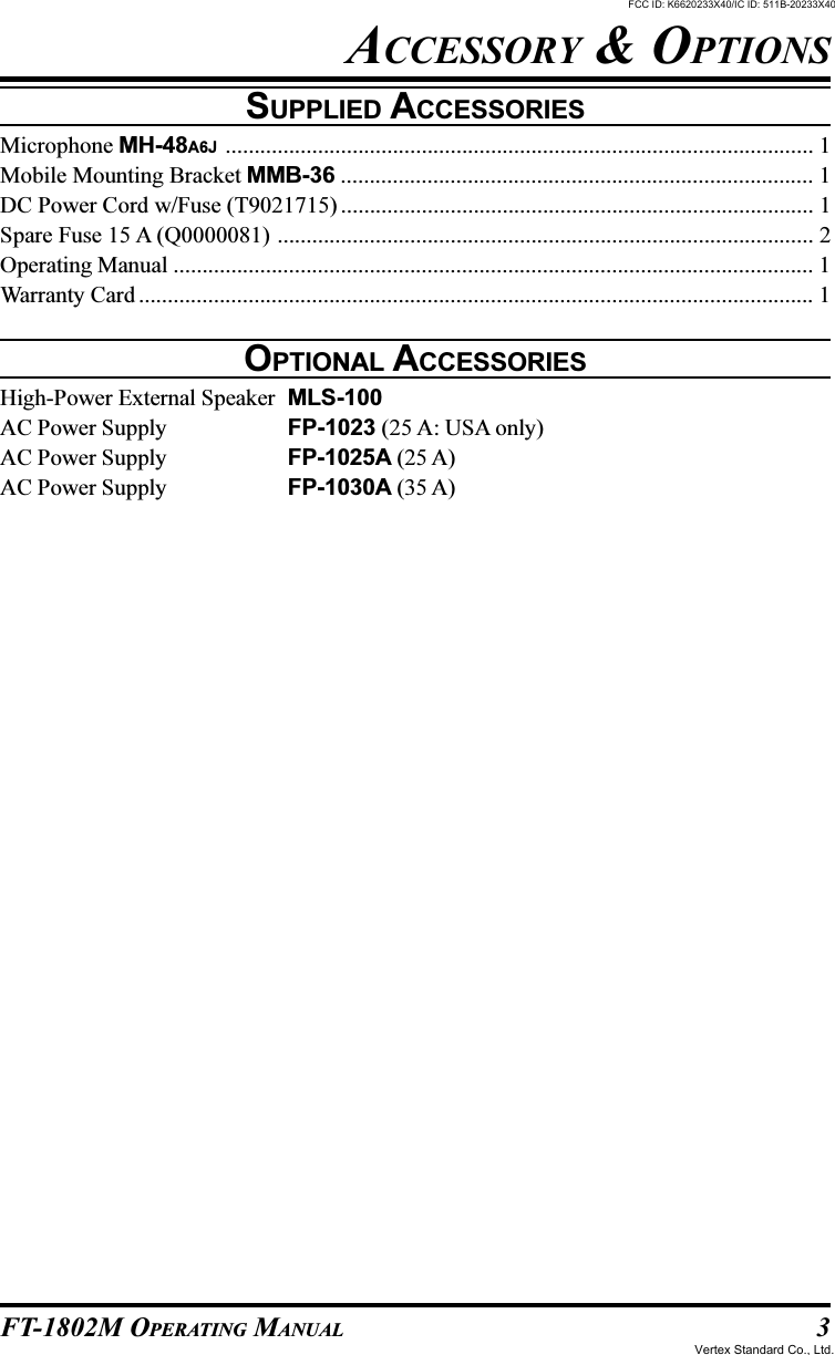
USERS MANUAL
Navigation menu
Upload a User Manual
Namespaces
Wiki Guide
HTML
PDF
Info
Views
User Manual
Discussion / Help
Navigation

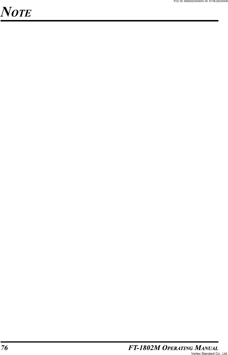
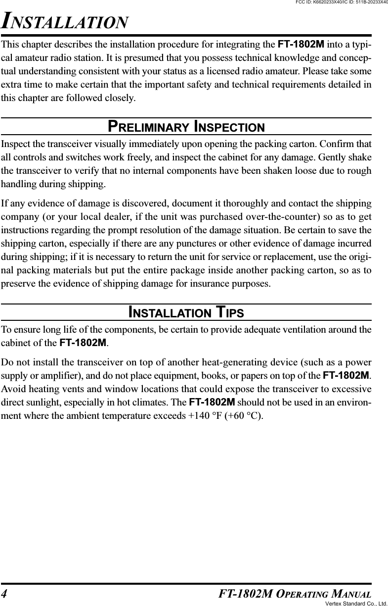
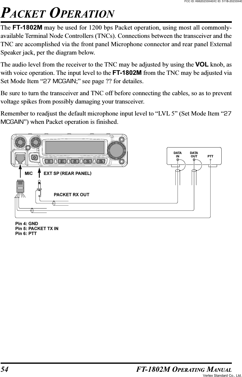
![2 FT-1802M OPERATING MANUALGeneralFrequency Range: Tx 144 - 146 MHz or 144 - 148 MHzRx 144 - 146 MHz or 136 - 174 MHzChannel Step: 5/10/12.5/15/20/25/50/100 kHzStandard Repeater Shift: ±600 kHzFrequency Stability: Better than ±10 ppm[–4 °F to +140 °F (–20 °C to +60 °C)]Modes of Emission: F2/F3Antenna Impedance: 50 Ohms, unbalancedSupply voltage: 13.8 V DC ±15%, negative groundCurrent Consumption (typical): Rx: less than 0.7 A, less than 0.3 A (squelched)Tx: 10 A (50 W) /7 A (25 W) /5 A (10 W) /4 A (5 W)Operating Temperature Range: –4° F to +140° F (–20° C to +60° C)Case Size (WxHxD): 5.5” x 1.6” x 5.7” (140 x 40 x 146 mm) (w/o knobs)Weight (Approx.): 2.6 lb (1.2 kg)TransmitterOutput Power: 50 W/25 W/10 W/5 WModulation Type: Variable ReactanceMaximum Deviation: ±5 kHz/±2.5 kHzSpurious Radiation: Better than –60 dBMicrophone Impedance: 2000 OhmsReceiverCircuit Type: Double Conversion SuperheterodyneIfs: 21.7 MHz & 450 kHzSensitivity (for 12dB SINAD): Better than 0.2 µVSelectivity (–6/–60dB): 12 kHz/28 kHzIF Rejection: Better than 70 dBImage Rejection: Better than 70 dBMaximum AF Output: 3 W into 4 Ohms @10 % THDSpecifications subject to change without notice or obligation. Specifications guaranteedonly within Amateur band.SPECIFICATIONSFCC ID: K6620233X40/IC ID: 511B-20233X40Vertex Standard Co., Ltd.](https://usermanual.wiki/Yaesu-Musen/20233X40/User-Guide-601500-Page-4.png)
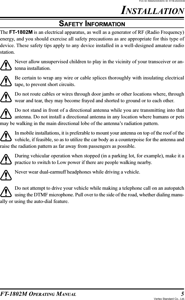


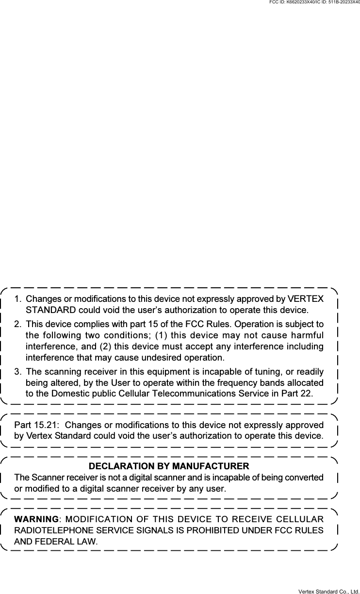
![10 FT-1802M OPERATING MANUALVOL KnobThis control adjusts the audio volume level. Clockwise rotation increases the volumelevel.SQL KnobThis control is used to silence background noise on the receiver. It should be advancedclockwise just to the point where the noise is silenced (and the “ ” indicator onthe display turns off), so as to provide the best sensitivity to weak signals.Microphone JackConnect the supplied MH-48A6J Hand Microphone to this jack.PWR KeyPress and hold this key for one second to toggle the transceiver’spower on and off.[ ] KeyThis key allows operation in conjunction with the Internet Connection feature.[MHz(SET)] KeyThis key allows tuning in 1-MHz steps (the MHz digits will blink on the display). Ifreceiving on a memory, pressing this key the first time activates the Memory Tuningmode, and pressing it again enables 1-MHz steps.Press and hold in this key for one second to activate the “Set” (Menu) mode.FRONT PANEL CONTROLS & SWITCHESMIC SW2MIC SW1GND +8VMIC INPUTPTT/CLONEFCC ID: K6620233X40/IC ID: 511B-20233X40Vertex Standard Co., Ltd.](https://usermanual.wiki/Yaesu-Musen/20233X40/User-Guide-601500-Page-12.png)
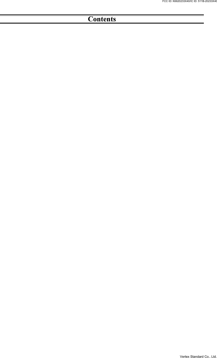
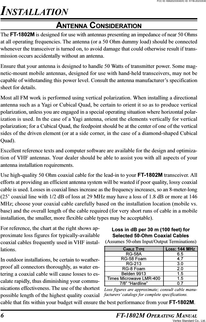
![11FT-1802M OPERATING MANUALFRONT PANEL CONTROLS & SWITCHES[REV(DW)] KeyDuring split-frequency operation, such as through a repeater, this key reverses the trans-mit and receive frequencies.*Press and hold in this key for one second to activate the Dual Watch feature, describedin the Operation chapter (“PRI” will be displayed on the LCD, indicating “PriorityChannel” monitoring).* Using the Menu, the “Reverse” feature may be disabled in favor of one-touch aaccess to the “Home” Channel. See page 33 for details.[LOW(A/N)] KeyPress this key momentarily to select the transmitter power output level.The available power levels are:HIGH (50W) MID (25W) LOW2 (10W) LOW1 (5W)To toggle the display between indication of the frequency and the channel’s Alpha/Numeric label, press and hold in this key for one second while receiving on that memorychannel.[D/MR(MW)] KeyPress this key momentarily to switch the frequency control among the VFO, MemorySystem, and Home channel.Press and hold in this key for one second to activate the Memory Storage mode.DIAL KnobThis 24-position detented rotary switch is used for tuning, memory selection and mostfunction settings. The microphone [UP]/[DWN] buttons duplicate the functions of thisknob.DisplayThe main digits on the display may show operating frequency, memory name, or any ofmany parameters during Menu setup.CTCSS(Continuous Tone Coded Squelch System)DCS (Digital Code Squelch)DTMF Memory ModeCTCSS/DCS/EPCS Bell PagingLock Feature ActiveProgrammable Memory ScanPriority ChannelMemory ModeMemory Channel NumberVFO ModeHome ChannelFrequency/Message AreaSKIP/Preferential Scan ChannelRepeater Shift DirectionLow TX Power SelectedTX IndicatorBUSY IndicatorNarrow DeviationS- and TX Power MeterFCC ID: K6620233X40/IC ID: 511B-20233X40Vertex Standard Co., Ltd.](https://usermanual.wiki/Yaesu-Musen/20233X40/User-Guide-601500-Page-13.png)
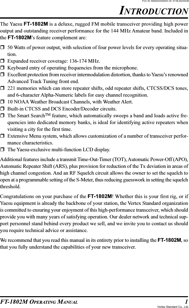
![12 FT-1802M OPERATING MANUALPTT SwitchPress this switch to transmit, and release itto receive.KeypadThese 16 keys generate DTMF tones duringtransmission.In the receive mode, these 16 keys can beused for direct frequency entry and/or directnumeric recall of the Memory channels.The [A], [B], [C], and [D] keys, on receive,replicate the functions of the front panel keys([MHz(SET)], [REV(D/W)], [LOW(A/N)],and [D/MR(MW)]). See the previous discus-sion.[P1]/[P2]/[P3]/[P4] ButtonsThese four keys are user programmable, al-lowing quick access to features used often.The default functions are described below.[P1] button (SQL OFF)Press this button to disables the noise and tone squelch systems.[P2] button (S SRCH)Press this button to activate the Smart Search feature.[P3] button (T SRCH)Press this button to activate the Tone Search feature.[P4] button (WX CH/T.CALL)In the USA version, pressing this button recall the “Weather” broadcast channel bank. Inthe EXP version, pressing this button activates T.CALL (1750 Hz) for repeater access.You can reprogram the [P1], [P2], [P3], and [P4] buttons for other functions, if de-sired. See page 45 for details.LAMP SwitchThis switch illuminates the Microphone’s keypad.LOCK SwitchThis switch locks out the Microphone’s buttons (except for the keypad and PTT switch).[UP]/[DWN] ButtonPress (or hold in) either of these buttons to tune (or scan up or down) the operatingfrequency or through the memory channels. In many ways, these buttons emulate thefunction of the (rotary) DIAL knob.MICROPHONE SWITCHESDTMF MICROPHONEMH-48FCC ID: K6620233X40/IC ID: 511B-20233X40Vertex Standard Co., Ltd.](https://usermanual.wiki/Yaesu-Musen/20233X40/User-Guide-601500-Page-14.png)
![15FT-1802M OPERATING MANUALBASIC OPERATIONFREQUENCY NAVIGATION1) Tuning DialRotating the DIAL knob allows tuning in the pre-programmed steps. Clockwise rotation of theDIAL knob causes the FT-1802M to be tuned toward a higher frequency, while counter-clock-wise rotation will lower the operating frequency.Press the [MHz(SET)] key momentarily, then rotate the DIAL knob, to change the frequencysteps to 1 MHz per step. This feature is extremely useful for making rapid frequency excursionsover the wide tuning range of the FT-1802M. Instead of pressing the [MHz(SET)] button, youmay also press the [A] key on the Microphone’s keypad to engage tuning in 1 MHz steps.2) Direct Keypad Frequency EntryThe keypad of the MH-48A6J DTMF Microphone may be used for direct entry of the oper-ating frequency.To enter a frequency from the MH-48A6J keypad, just press the numbered digits in theproper sequence. There is no “decimal point” key on the MH-48A6J keypad. However, thereis a short-cut for frequencies ending in zero: press the [#] key after the last non-zero digit.Examples: To enter 146.520 MHz, press [1] [4] [6] [5] [2] [0]To enter 146.000 MHz, press [1] [4] [6] [#]If you cannot get the radio to accept the frequency entry, it is possible that thechannel steps are set to an incompatible value (e.g. if you have 25 kHz steps set,you cannot set a frequency of 146.520 MHz). See page 19 to learn how to change thechannel step size.3) ScanningFrom the VFO mode, press the microphone’s [UP]/[DWN] keys momentarily to initiatescanning toward a higher- or lower frequency, respectively. The FT-1802M will stop whenit receives a signal strong enough to break through the squelch threshold. The FT-1802Mwill then hold on that frequency according to the setting of the “Resume” mode (Menu “23SCAN)”; see page 34).If you wish to reverse the direction of the scan (i.e. toward a lower frequency, instead of ahigher frequency), just rotate the DIAL knob one click in the counter-clockwise directionwhile the FT-1802M is scanning. The scanning direction will be reversed. To revert toscanning toward a higher frequency once more, rotate the DIAL knob one click clockwise.Press the [UP]/[DWN] keys again to cancel scanning. You may also press the PTT buttonmomentarily; scanning will stop, but you will not transmit until you release the PTT button,and press it again.If you have enabled the “Severe Weather Alert” feature, you will occasionally no-tice “WX” channels interspersed with the regular channels you are scanning. Thisis normal, because your radio is constantly monitoring for weather alerts. See page 17.FCC ID: K6620233X40/IC ID: 511B-20233X40Vertex Standard Co., Ltd.](https://usermanual.wiki/Yaesu-Musen/20233X40/User-Guide-601500-Page-17.png)
![16 FT-1802M OPERATING MANUALTRANSMISSIONTo transmit, simply close the PTT (Push To Talk) switch on the microphone when the fre-quency is clear. Hold the microphone approximately 1” (25 mm) from your mouth, andspeak into the microphone in a normal voice level. When your transmission is complete,release the PTT switch; the transceiver will revert to the receive mode.During transmission, the “ ” indicator will appear at the upper left corner on the display.Changing the Transmitter Power LevelYou can select from among a total of four transmit power levels on your FT-1802M.To change the power level, press the [LOW(A/N)] key (or the microphone’s [C] key toselect one of four power settings. These power levels will be stored, in memory registers, atthe time of memory storage (see page 30 for details on Memory operation).During transmission, the Bar Graph will deflect in the display, according to the power out-put selected.BASIC OPERATIONLow 1 (5 watts)Low 2 (10 watts)MID (25 watts)HIGH (50 watts)FCC ID: K6620233X40/IC ID: 511B-20233X40Vertex Standard Co., Ltd.](https://usermanual.wiki/Yaesu-Musen/20233X40/User-Guide-601500-Page-18.png)
![17FT-1802M OPERATING MANUALWEATHER BROADCAST RECEPTIONThe FT-1802M includes a unique feature which allows reception of weather broadcasts inthe 160-MHz frequency range. Ten standard Weather Broadcast channels are pre-loadedinto a special memory bank.To listen to a Weather Broadcast Channel:1. Press the Microphone’s [P4] button to recall theWeather Broadcast channels.2. Turn the DIAL knob to select the desired WeatherBroadcast channel.3. If you wish to check the other channels for activityby scanning, just press the Microphone’s PTTswitch.4. To exit to normal operation, press the [P4] buttonagain. Operation will return to the VFO or Memorychannel you were operating on before you began Weather Broadcast operation.Severe Weather Alert FeatureIn the event of extreme weather disturbances, such as storms and hurricanes, the NOAA(National Oceanic and Atmospheric Administration) sends a weather alert accompanied bya 1050 Hz tone and subsequent weather report on one of the NOAA weather channels.ADVANCED OPERATIONCH0102030405CH0607080910FREQUENCY162.550 MHz164.400 MHz162.475 MHz162.425 MHz162.450 MHzFREQUENCY162.500 MHz165.525 MHz161.650 MHz161.775 MHz163.275 MHzFCC ID: K6620233X40/IC ID: 511B-20233X40Vertex Standard Co., Ltd.](https://usermanual.wiki/Yaesu-Musen/20233X40/User-Guide-601500-Page-19.png)
![18 FT-1802M OPERATING MANUALLOCK FEATURETo order to prevent accidental frequency change or inadvertent transmission, various as-pects of the FT-1802M’s keys and knob may be locked out. The possible lockout combina-tions are:KEY: Just the front panel keys are locked outDIAL: Just the front panel DIAL knob is locked outK+D: Both the keys and DIAL knob are locked outPTT: The PTT switch is locked (TX not possible)K+P: Both keys and PTT switch are locked outD+P: Both DIAL knob and PTT switch are locked outALL: All of the above are locked outOFF: The Lock feature is disabledTo lock out some or all of the keys, use the “Set” (Menu) mode, described in detail begin-ning on page 51:1. Press and hold in the [MHz(SET)] key for one second, then rotate the DIAL knob toselect “26 LOCK.”2. Press the [MHz(SET)] key, then rotate the DIAL knob to set the display to one of theselections shown above.3. Press and hold in the [MHz(SET)] key for one second to save your new setting and exitto normal operation.When the Lock feature is activated, the “ ” icon willappear on the LCD.To disable the Lock feature, repeat the above process, selecting “OFF” in step 2 above.KEYPAD BEEPERA key/button beeper provides useful audible feedback whenever a key/button is pressed. Ifyou want to turn the beeper off (or back on again):1. Press and hold in the [MHz(SET)] key for one second, then rotate the DIAL knob toselect “6 BEEP.”2. Press the [MHz(SET)] key, then rotate the DIAL knob to set the display to “OFF.”3. Press and hold in the [MHz(SET)] key for one second to save your new setting and exitto normal operation.ADVANCED OPERATIONFCC ID: K6620233X40/IC ID: 511B-20233X40Vertex Standard Co., Ltd.](https://usermanual.wiki/Yaesu-Musen/20233X40/User-Guide-601500-Page-20.png)
![19FT-1802M OPERATING MANUALCHANNEL STEP SELECTIONTuning steps are factory preset to default increments which are appropriate for the countryto which this radio is exported. You may have a reason to use a different step size, however,and here is the procedure for changing the channel steps:1. Press and hold in the [MHz(SET)] key for one second, then rotate the DIAL knob toselect “50 STEP.”2. Press the [MHz(SET)] key, then rotate the DIAL knob to select the desired step size(5/10/12.5/15/20/25/50/100 kHz).3. Press and hold in the [MHz(SET)] key for one second to save your new setting and exitto normal operation.DISPLAY BRIGHTNESSThe FT-1802M display illumination has been specially engineered to provide high visibil-ity with minimal disruption of your “night vision” while you are driving. The brightness ofthe display is manually adjustable, using the following procedure:1. Press and hold in the [MHz(SET)] key for one second, then rotate the DIAL knob toselect “16 DIMMER.”2. Press the [MHz(SET)] key, then rotate the DIAL knob to select a comfortable brightnesslevel (0 - 10).3. Press and hold in the [MHz(SET)] key for one second to save your new setting and exitto normal operation.ADVANCED OPERATIONFCC ID: K6620233X40/IC ID: 511B-20233X40Vertex Standard Co., Ltd.](https://usermanual.wiki/Yaesu-Musen/20233X40/User-Guide-601500-Page-21.png)
![20 FT-1802M OPERATING MANUALRF SQUELCHA special RF Squelch feature is provided on this radio. This feature allows you to set thesquelch so that only signals exceeding a certain S-meter level will open the squelch.To set up the RF squelch circuit for operation, use the following procedure:1. Press and hold in the [MHz(SET)] key for one second, then rotate the DIAL knob toselect “42 RF SQL.”2. Press the [MHz(SET)] key, then rotate the DIAL knob to select the desired signal strengthlevel for the squelch threshold (S1 - S9 or OFF).3. Press and hold in the [MHz(SET)] key for one second to save your new setting and exitto normal operation.The receiver’s squelch will open based on the highest level set by the two squelchsystem “Noise Squelch and RF Squelch). For example:1) If the Noise Squelch (SQL control) is set so that signals at a level of S-3 will open thesquelch, but the RF Squelch (Menu #20) is set to “S-9,” the squelch will only open onsignals which are S-9 or stronger on the S-meter.2) If the RF Squelch is set to “S-3,” but the Noise Squelch is set to a high level which willonly pass signals which are Full Scale on the S-meter, the squelch will only open onsignals which are Full Scale on the S-meter. In this case, the Noise Squelch overrides theaction of the RF Squelch.ADVANCED OPERATIONFCC ID: K6620233X40/IC ID: 511B-20233X40Vertex Standard Co., Ltd.](https://usermanual.wiki/Yaesu-Musen/20233X40/User-Guide-601500-Page-22.png)
![21FT-1802M OPERATING MANUALREPEATER OPERATIONThe FT-1802M includes a host of convenience features which makes operation on amateurrepeaters both efficient and enjoyable.This transceiver offers three methods of setting up split-frequency operation on repeaters:Manual selection of preset repeater shifts (Standard Repeater Shift);Automatic Repeater Shift (ARS), providing automatic activation of repeater shiftsduring designated repeater frequency subbands; andIndependently stored transmit and receive frequencies (typically not correspondingto established repeater frequency shifts).STANDARD REPEATER SHIFTTo activate the standard shift manually, you may use the Set (Menu) mode:1. Press and hold in the [MHz(SET)] key for one second, then rotate the DIAL knob toselect “43 RPTR.”2. Press the [MHz(SET)] key, then rotate the DIAL knob to select the desired shift direc-tion (–RPT, +RPT, or SIMP).3. Press and hold in the [MHz(SET)] key for one second to save your new setting and exitto normal operation.You also may program one of the Microphone’s programmable keys ([P1] ~ [P4]) toallow quick access to the above procedure. See page 45 for details on the setup ofthe programmable keys.With repeater shift activated, you can temporarily reverse the transmit and receive frequen-cies by pressing the [REV(DW)] key (or microphone’s [B] key). Use this feature to displaythe transmit frequency without transmitting, and to check the strength of signals on a re-peater uplink frequency (so as to determine whether or not a particular station is within“Simplex” range, for example).The repeater offset is fixed to 600 kHz from the factory. You can change the offset by thefollowing procedure, if needed for vacation travel or other purposes:1. Press and hold in the [MHz(SET)] key for one second, then rotate the DIAL knob toselect “46 SHIFT.”2. Press the [MHz(SET)] key, then rotate the DIAL knob to set the desired offset. Note thatthe resolution of the “standard” repeater shift is to the nearest 50 kHz multiple.3. Press and hold in the [MHz(SET)] key for one second to save your new setting and exitto normal operation.Do not use this procedure for programming of an “odd split” type repeater pair!The process for programming odd splits is shown on page 23.FCC ID: K6620233X40/IC ID: 511B-20233X40Vertex Standard Co., Ltd.](https://usermanual.wiki/Yaesu-Musen/20233X40/User-Guide-601500-Page-23.png)
![22 FT-1802M OPERATING MANUALREPEATER OPERATIONAUTOMATIC REPEATER SHIFTThe ARS (Automatic Repeater Shift) feature in this transceiver allows easy and convenientrepeater operation by automatically activating the repeater shift function whenever you tuneto a standard repeater subband. The ARS function is preset at the factory to conform to thestandards for the country to which it is exported.The ARS function is enabled at the factory. To disable it:1. Press and hold in the [MHz(SET)] key for one second, then rotate the DIAL knob toselect “04 ARS.”2. Press the [MHz(SET)] key, then rotate the DIAL knob to change the display to “OFF.”3. Press and hold in the [MHz(SET)] key for one second to save your new setting and exitto normal operation.To enable the ARS function again, select to “ON” in step 2 above.European VersionVersion A145.1 145.5145.6 145.8146.0 146.4 147.0 147.6 148.0146.6 147.4ARS-Repeater SubbandsFCC ID: K6620233X40/IC ID: 511B-20233X40Vertex Standard Co., Ltd.](https://usermanual.wiki/Yaesu-Musen/20233X40/User-Guide-601500-Page-24.png)
![23FT-1802M OPERATING MANUALREPEATER OPERATIONSEPARATE TRANSMIT FREQUENCY MEMORIES (“ODD SPLITS”)All memory channels can store independent receive and transmit frequencies, to accommo-date occasional non-standard offsets with greater frequency resolution than is available us-ing the “standard” shift feature.1. First store the receive (repeater output) frequency. In the VFO mode, tune the transceiverto the desired receive frequency. Now press and hold in the [D/MR(MW)] key on thefront panel for one second.2. Within five seconds of pressing the [D/MR(MW)] key, use the DIAL knob or microphone’s[UP]/[DWN] buttons to select the desired memory channel into which you wish to storethis frequency pair.3. Now press the [D/MR(MW)] key momentarily to store the receive frequency into theselected memory.4. Next store the transmit (repeater input) frequency. Since you are still in the VFO mode,tune the transceiver to the desired transmit frequency.5. Now press and hold in the [D/MR(MW)] key for one second.6. Press and hold in the PTT switch, and press the [D/MR(MW)] key momentarily whileholding in the PTT switch. This will not cause transmission, but rather it will instruct thetransceiver that you are programming a separate transmit frequency into memory.When you have finished the above procedure, press the [D/MR(MW)] key momentarily.The channel number and repeater downlink frequency will appear on the display. If youpress the PTT switch, you will observe the display changing to indicate the repeater’s uplinkfrequency. Note also that the display shows “ ” in the upper left-hand corner; this indi-cates that an “odd” (non-standard) shift has been stored on this channel.FCC ID: K6620233X40/IC ID: 511B-20233X40Vertex Standard Co., Ltd.](https://usermanual.wiki/Yaesu-Musen/20233X40/User-Guide-601500-Page-25.png)
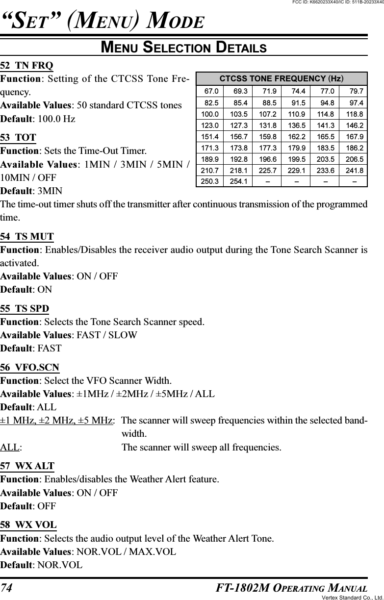
![24 FT-1802M OPERATING MANUALCTCSS OPERATIONMany repeater systems require that a very-low-frequency audio tone be superimposed onyour FM carrier in order to activate the repeater. This helps prevent false activation of therepeater by radar or spurious signals from other transmitters. This tone system, called“CTCSS” (Continuous Tone Coded Squelch System), is included in your FT-1802M, and isvery easy to activate.CTCSS setup involves two actions: setting the Tone Mode and then setting of theTone Frequency. These actions are set up by using the Set (Menu) mode, selec-tions #49 (SQ TYP) and #52 (TN FRQ).1. Press and hold in the [MHz(SET)] key for one second, then rotate the DIAL knob toselect “49 SQ TYP.”2. Press the [MHz(SET)] key, then rotate the DIAL knob so that “TONE” appears on thedisplay; this activates the CTCSS Encoder, which allows repeater access.3. Rotating the DIAL knob one more click clockwise in the above step will cause “TSQL”to appear. When “TSQL” appears, this means that the Tone Squelch system is active,which mutes your FT-1802M’s receiver until it receives a call from another radio send-ing out a matching CTCSS tone. This can help keep your radio quiet until a specific callis received, which may be helpful while operating in congested areas.1) You may notice a “RV TN” indication on the display while you rotate theDIAL knob in this step; this means that the Reverse Tone Squelch system isactive, which mutes your FT-1802M’s receiver (instead of opening the squelch) whenit receives a call from the radio sending a matched CTCSS tone. The “T SQ” icon willblink on the display when the Reverse Tone Squelch system is activated.2) You may notice a “DCS” indication on the display while you rotate the DIAL knobstill more. We’ll discuss the Digital Code Squelch system shortly.4. When you have made your selection of the CTCSS tone mode, press the [MHz(SET)]key momentarily, then rotate the DIAL knob one click counter-clockwise to select Menu“52 TN FRQ.” This Menu selection allows setting of the CTCSS tone frequency to beused.5. Press the [MHz(SET)] key to enable adjust-ment of the CTCSS frequency.6. Rotate the DIAL knob until the display indi-cates the Tone Frequency you need to be us-ing.7. When you have made your selection, pressand hold in the [MHz(SET)] key for onesecond to save the new setting and exit tonormal operation.CTCSS/DCS/EPCS OPERATIONCTCSS TONE FREQUENCY (Hz) 67.0 69.3 71.9 74.4 77.0 79.7 82.5 85.4 88.5 91.5 94.8 97.4100.0 103.5 107.2 110.9 114.8 118.8123.0 127.3 131.8 136.5 141.3 146.2151.4 156.7 159.8 162.2 165.5 167.9171.3 173.8 177.3 179.9 183.5 186.2189.9 192.8 196.6 199.5 203.5 206.5210.7 218.1 225.7 229.1 233.6 241.8250.3 254.1 ––––FCC ID: K6620233X40/IC ID: 511B-20233X40Vertex Standard Co., Ltd.](https://usermanual.wiki/Yaesu-Musen/20233X40/User-Guide-601500-Page-26.png)
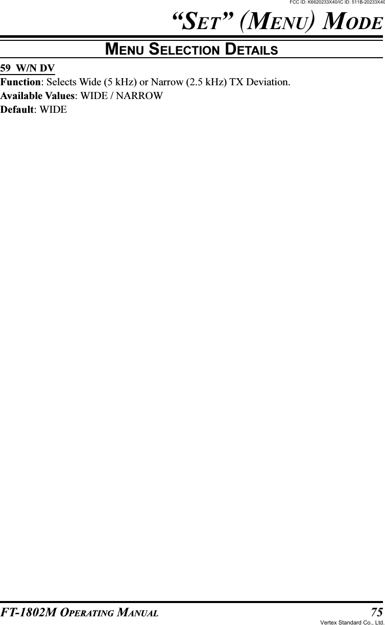
![25FT-1802M OPERATING MANUALYour repeater may or may not re-transmit a CTCSS tone - some systems just useCTCSS to control access to the repeater, but don’t pass it along when transmit-ting. If the S-Meter deflects, but the FT-1802M is not passing audio, repeat steps “1”through “3” above, but rotate the DIAL knob so that “T ENC” appears - this will allowyou to hear all traffic on the channel being received.You may use the Menu to re-program one of the Microphone’s programmable keys forquick access to Menu #52 (TN FRQ), from which you can perform the above setup pro-cedure. See page 45 for details on the setup of the programmable keys.DCS OPERATIONAnother form of tone access control is Digital Code Squelch, or DCS. It is a newer, moreadvanced tone system which generally provides more immunity from false paging than doesCTCSS. The DCS Encoder/Decoder is built into your FT-1802M, and operation is verysimilar to that just described for CTCSS. Your repeater system may be configured for DCS;if not, it is frequently quite useful in Simplex operation if your friend(s) use transceiversequipped with this advanced feature.Just as in CTCSS operation, DCS requires that you set the Tone Mode to DCS andthat you select a Tone Code.1. Press and hold in the [MHz(SET)] key for one second, then rotate the DIAL knob toselect “49 SQ TYP.”2. Press the [MHz(SET)] key, then rotate the DIAL knob until “DCS” appears on the dis-play; this activates the DCS Encoder/Decoder.3. Now press the [MHz(SET)] key momentarily, then rotate the DIAL knob to select Menu“14 DCS CD.”4. Press the [MHz(SET)] key momentarily toenable the adjustment of the DCS code.5. Rotate the DIAL knob to select the desiredDCS Code (a three-digit number).6. When you have made your selection, pressand hold in the [MHz(SET)] key for onesecond to save the new setting and exit tonormal operation.Remember that the DCS is an Encode/Decode system, so your receiver will re-main muted until a matching DCS code is re-ceived on an incoming transmission. Switch the DCS off when you’re just tuning aroundthe band!CTCSS OPERATIONCTCSS/DCS/EPCS OPERATIONDCS CODE023 025 026 031 032 036 043 047 051 053054 065 071 072 073 074 114 115 116 122125 131 132 134 143 145 152 155 156 162165 172 174 205 212 223 225 226 243 244245 246 251 252 255 261 263 265 266 271274 306 311 315 325 331 332 343 346 351356 364 365 371 411 412 413 423 431 432445 446 452 454 455 462 464 465 466 503506 516 523 526 532 546 565 606 612 624627 631 632 654 662 664 703 712 723 731732 734 743 754 – – – – – –FCC ID: K6620233X40/IC ID: 511B-20233X40Vertex Standard Co., Ltd.](https://usermanual.wiki/Yaesu-Musen/20233X40/User-Guide-601500-Page-27.png)
![26 FT-1802M OPERATING MANUALTONE SEARCH SCANNINGIn operating situations where you don’t know the CTCSS tone or DCS code being used byanother station or stations, you can command the radio to listen to the incoming signal andscan in search of the tone being used. Two things must be remembered in this regard:You must be sure that your repeater uses the same tone type (CTCSS vs. DCS).Some repeaters do not pass the CTCSS tone or DCS code; you may have to listen to thestation(s) transmitting on the repeater uplink (input) frequency in order to allow ToneSearch Scanning to work.To scan for the tone in use:1. Set the radio up for either CTCSS or DCS Decoder operation (see the previous discus-sion). In the case of CTCSS, “TSQ” will appear on the display; in the case of DCS,“DCS” will appear on the display.2. Press the Microphone’s [P3] key momentarily to start scanning for the incoming CTCSSor DCS tone/code.3. When the radio detects the correct tone or code, it will halt on that tone/code, and audiowill be allowed to pass.4. Press and hold in the [MHz(SET)] key for one second to lock in that tone/code and exitto normal operation.If the Tone Scan feature does not detect a tone or code, it will continue to scanindefinitely. When this happens, it may be that the other station is not sending anytone. You can press the Microphone’s [P3] key to halt the scan at any time.You may listen to the (muted) signal from the other station during Tone Scanning when SetMode Item “54 TS MUT” is set to “OFF.” See page ?? for details. You can also change theTone Search scanning speed, using Set Mode Item “55 TS SPD.” See page ?? for details.Tone Scanning works either in the VFO or Memory modes.CTCSS/DCS/EPCS OPERATIONFCC ID: K6620233X40/IC ID: 511B-20233X40Vertex Standard Co., Ltd.](https://usermanual.wiki/Yaesu-Musen/20233X40/User-Guide-601500-Page-28.png)
![27FT-1802M OPERATING MANUALEPCS (ENHANCED PAGING & CODE SQUELCH) OPERATIONThe FT-1802M includes an Enhanced CTCSS tone encoder/decoder and a dedicated micro-processor providing paging and selective calling features. This allows you to place a call to aspecific station (Paging), and to receive calls of your choice directed only to you (Code Squelch).The paging and code squelch systems use two pairs of (alternately switched) CTCSS toneswhich are stored in the pager memories. Basically, your receiver remains silent until it re-ceives the CTCSS tone pair that matches those stored in the Receiving Pager Memory. Thesquelch then opens so the caller is heard, and the paging ringer immediately sounds, ifactivated. When you close the PTT switch to transmit, the CTCSS tone pair which is storedin the Transmitting Pager Memory will be transmitted automatically.On the paged radio, the squelch will close automatically after the incoming page ends.Storing the CTCSS Tone Pairs for EPCS Operation1. Press and hold in the [MHz(SET)] key for one second to enter the Set mode.2. Rotate the DIAL knob to select “34 PAG.CDR” for the Receiving CTCSS Tone Pair or“35 PAG.CDT“34 for the Transmitting CTCSS Tone Pair.3. Press the [MHz(SET)] key momentarily to enable adjustment of this Set Mode Item.4. Rotate the DIAL knob to set the CTCSS Tone number which corresponds to the first toneof the CTCSS Tone Pair.5. Press the [REV(DW)] or [LOW(A/N)] key, then rotate the DIAL knob to set the CTCSSTone number which corresponds to the second tone of the CTCSS Tone Pair.6. Press and hold in the [MHz(SET)] key for one second to lock in that tone/code and exitto normal operation.The FT-1802M does not recognize the order of the 1st tone and the 2nd tone. Inother words, for example, the FT-1802M considers both CTCSS pairs “10, 35”and “35, 10” to be identical.CTCSS/DCS/EPCS OPERATIONHz67.069.371.974.477.079.782.585.488.591.5No.01020304050607080910Hz94.897.4100.0103.5107.2110.9114.8118.8123.0127.3No.11121314151617181920Hz131.8136.5141.3146.2151.4156.7159.8162.2165.5167.9No.21222324252627282930Hz171.3173.8177.3179.9183.5186.2189.9192.8196.6199.5No.31323334353637383940Hz203.5206.5210.7218.1225.7229.1233.6241.8250.3254.1No.41424344454647484950CTCSS TONE NUMBERFCC ID: K6620233X40/IC ID: 511B-20233X40Vertex Standard Co., Ltd.](https://usermanual.wiki/Yaesu-Musen/20233X40/User-Guide-601500-Page-29.png)
![28 FT-1802M OPERATING MANUALActivating the Enhanced Paging & Code Squelch System1. Press and hold in the [MHz(SET)] key for one second, then rotate the DIAL knob toselect “32 PAGER.”2. Press the [MHz(SET)] key, then rotate the DIAL knob to set this Menu item to “ON.”3. Press and hold in the [MHz(SET)] key for one second to save the new setting and exit tonormal operation.4. To disable the Enhanced Paging & Code Squelch, just repeat the above procedure, rotat-ing the DIAL knob to select “OFF” in step 2 above.When the Enhanced Paging & Code Squelch feature is activated, the “P”notation will ap-pear at the 100 MHz digit of the frequency display.Paging Anser BackWhen you press the PTT switch to respond to a page call, the FT-1802M transmits theTranmitting CTCSS Tone pair. This tone pair will open the Code Squelch of the callingstation. If you prefer, you can have the FT-1802M respond to page calls automatically(“transpond”).To enable this feature:1. Press and hold in the [MHz(SET)] key for one second, then rotate the DIAL knob toselect “33 PAG.ABK.”2. Press the [MHz(SET)] key, then rotate the DIAL knob to set this Menu item to “ON.”3. Press and hold in the [MHz(SET)] key for one second to save the new setting and exit tonormal operation.4. To disable the Paging Anser Back feature, just repeat the above procedure, rotating theDIAL knob to select “OFF” in step 2 above.EPCS (ENHANCED PAGING & CODE SQUELCH) OPERATIONCTCSS/DCS/EPCS OPERATIONFCC ID: K6620233X40/IC ID: 511B-20233X40Vertex Standard Co., Ltd.](https://usermanual.wiki/Yaesu-Musen/20233X40/User-Guide-601500-Page-30.png)
![29FT-1802M OPERATING MANUALCTCSS/DCS/EPCS BELL OPERATIONDuring CTCSS Decode, DCS, or EPCS operation, you may set up the FT-1802M such thata ringing “bell” sound alerts you to the fact that a call is coming in. Here is the procedure foractivating the CTCSS/DCS/EPCS Bell:1. Set the transceiver up for CTCSS Decode (“Tone Squelch”), DCS, or EPCS operation,as described previously.2. Adjust the operating frequency to the desired channel.3. Press and hold in the [MHz(SET)] key for one second, then rotate the DIAL knob toselect “7 BELL.”4. Rotate the DIAL knob to set the desired number of rings of the Bell. The availablechoices are 1, 3, 5, or 8 rings, CNTNUE (continuous ringing), or OFF.5. Press and hold in the [MHz(SET)] key for one second to save the new setting and exit tonormal operation.When you are called by a station whose transceiver is sending a CTCSS tone, DCS code, orCTCSS code pair which matches that set into your Decoder, the Bell will ring in accordancewith this programming.When the CTCSS/DCS/EPCS Bell is activeted, the “ ” icon will appear on the display.CTCSS/DCS/EPCS OPERATIONFCC ID: K6620233X40/IC ID: 511B-20233X40Vertex Standard Co., Ltd.](https://usermanual.wiki/Yaesu-Musen/20233X40/User-Guide-601500-Page-31.png)
![30 FT-1802M OPERATING MANUALSPLIT TONE OPERATIONThe FT-1802M can be operated in a “Split Tone” configuration, to enable operation onrepeaters using a mix of both CTCSS and DCS control via the Set mode.1. Press and hold in the [MHz(SET)] key for one second, then rotate the DIAL knob toselect “48 SPLIT.”2. Press the [MHz(SET)] key, then rotate the DIAL knob to set this Menu item to “ON” (toenable the Split Tone feature).3. Press and hold in the [MHz(SET)] key for one second to save the new setting and exit tonormal operation.When the Split Tone feature is activated, you can see the following additional parametersfollowing the “RV TN” parameter (while selecting the tone mode by Set mode item “49SQL.TYP”):T CODE: DCS Encode only (the “DCS” icon will blink during operation)T DCS: Encodes a CTCSS Tone and Decodes a DCS code(the “T” icon will blink and the “DCS” icon will appear during operation)D TONE: Encodes a DCS code and Decodes a CTCSS Tone(the “T SQ” icon will appear and “DC” icons will blink during operation)Select the desired operating mode from the selections shown above.CTCSS/DCS/EPCS OPERATIONFCC ID: K6620233X40/IC ID: 511B-20233X40Vertex Standard Co., Ltd.](https://usermanual.wiki/Yaesu-Musen/20233X40/User-Guide-601500-Page-32.png)
![32 FT-1802M OPERATING MANUALDTMF AUTODIALER OPERATIONDTMF AUTODIALER OPERATIONNine DTMF Autodialer memories are available on the FT-1802M. These DTMF Autodialermemories can store up to 16 digits of a telephone number for repeater autopatch or otheruse.To load DTMF Autodialer memories, use the following procedure:1. Press and hold in the [MHz(SET)] key for one second, then rotate the DIAL knob toselect “19 DT SET.”2. Press the [MHz(SET)] key, then rotate the DIAL knob to select the DTMF Autodialermemory channel number into which you wish store a telephone number (“C0” to “C9”).3. Press the [REV(DW)] key momentarily, then rotate the DIAL knob to select the firstdigit of the telephone number you wish to store.4. When you have selected the correct digit, press the [LOW(A/N)] key momentarily. Now,rotate the DIAL knob to select the second of 16 available numbers in the current DTMFAutodialer memory register.5. Repeat this procedure for each digit in the telephone number. If you a mistake, press the[REV(DW)] key to move back to the first digit, then re-enter the correct number.6. When entry of all digits is complete, press the [MHz(SET)] key.7. If you wish to store another DTMF string, repeat steps 2 through 6 above.8. Press and hold in the [MHz(SET)] key for one second to save the new setting and exit tonormal operation.To transmit the memorized telephone number, use the following procedure:1. Press and hold in the [MHz(SET)] key for one second, then rotate the DIAL knob toselect “17 DT A/M.”2. Press the [MHz(SET)] key, then rotate the DIAL knob to set this Set Mode Item to“AUTO.”3. Press and hold in the [MHz(SET)] key for one second to save the new setting and exitto normal operation.4. In the Autodialer mode, which you just engaged, first press the PTT switch, then pressthe microphone’s numeric key ([0] through [9]) corresponding to the DTMF memorystring you wish to send. Once the string begins, you may release the PTT switch, as thetransmitter will be held “on the air” until the DTMF string is completed.FCC ID: K6620233X40/IC ID: 511B-20233X40Vertex Standard Co., Ltd.](https://usermanual.wiki/Yaesu-Musen/20233X40/User-Guide-601500-Page-34.png)
![33FT-1802M OPERATING MANUALDTMF AUTODIALER OPERATIONTo disable the Autodialer function mode, select “MANUAL” in step 2 above.The speed at which the DTMF digits are sent can be changed. Two speed levels are avail-able: Low (10 digits per second) and High (20 digits per second: default). To toggle betweenLow and High speed, use the following procedure:1. Press and hold in the [MHz(SET)] key for one second, then rotate the DIAL knob toselect “20 DT SPD.”2. Press the [MHz(SET)] key, then rotate the DIAL knob to select the desired speed (“50”:High speed or “100”: Low speed).3. Press and hold in the [MHz(SET)] key for one second to save the new setting and exit tonormal operation.You can also set a longer delay between the time your transmitter is keyed and the firstDTMF digit is sent. To set the delay time, use the following procedure:1. Press and hold in the [MHz(SET)] key for one second, then rotate the DIAL knob toselect “18 DT DLY.”2. Press the [MHz(SET)] key, then rotate the DIAL knob to select the desired speed (50/250/450/750/1000 ms).3. Press and hold in the [MHz(SET)] key for one second to save the new setting and exit tonormal operation.DTMF AUTODIALER OPERATIONFCC ID: K6620233X40/IC ID: 511B-20233X40Vertex Standard Co., Ltd.](https://usermanual.wiki/Yaesu-Musen/20233X40/User-Guide-601500-Page-35.png)
![34 FT-1802M OPERATING MANUALMEMORY STORAGEA wide array of memory resources are available on the FT-1802M. A total of 221 memoriesare available, and each may be appended with an alpha-numeric label of up to six characters,for quick channel recognition.The “basic” memory bank for the FT-1802M consists of 200 memories. Let’s learn thesimple procedure for storing and recalling a frequency, then we can move on to some of themore advanced memory features.To store a frequency into memory:1. In the VFO mode, select the desired frequency, repeater shift, CTCSS/DCS tone, andTX power level.2. Press and hold in the [D/MR(MW)] key for one second. A memory number will appearin the bottom right-hand corner of the display. If the channel number is blinking, therecurrently is no data stored on that channel; if the channel number is not blinking, thatchannel is currently “occupied” by other frequency data, and you won’t want to use thatchannel unless the data is no longer of interest.3. Within five seconds of pressing the [D/MR(MW)] key, use the DIAL knob to select thedesired memory into which you wish to store the frequency.4. Press the [D/MR(MW)] key again, this time momentarily, to store the displayed datainto the selected memory channel slot. The memory label will disappear (since you arestill operating in the VFO mode).5. To store other frequencies, repeat steps 1 through 4, remembering to set the repeatershift, CTCSS/DCS tone, and TX power level, as appropriate.The above procedure will be used for virtually all memory storage circumstances.If you need to program a frequency pair that uses a non-standard shift (“oddsplit”), use the procedure described on page 23.MEMORY OPERATIONFCC ID: K6620233X40/IC ID: 511B-20233X40Vertex Standard Co., Ltd.](https://usermanual.wiki/Yaesu-Musen/20233X40/User-Guide-601500-Page-36.png)
![35FT-1802M OPERATING MANUALMEMORY OPERATIONMEMORY RECALLOnce you have stored the memory or memories desired, you must now switch from the“VFO” mode to the “Memory Recall” mode, so you can operate on the just-stored memorychannels.1. Press the [D/MR(MW)] key, repeatedly if necessary, until the “MR” icon and a memorychannel number appear on the display; this indicates that the “Memory Recall” mode isnow engaged.2. When more than one memory has been stored, use the DIAL knob to select any pf theprogrammed memories for operation. Alternatively, the microphone’s [UP] or [DWN]button may be used to step or scan through the available memories. When using themicrophone’s buttons, press the button momentarily to move one step up or down; pressand hold in the [UP] or [DWN] button for one second to begin memory scanning.Memory Recall from the Microphone’s Keypad:While operating in the Memory Recall mode, the keypad of the MH-48A6J Microphone maybe used for direct recall of memory channels.To do this, press the Channel Number you wish to recall, then press the [#] key. For ex-ample, to recall Memory Channel “5,” press [5] []. To recall Memory Channel “118,”press [1] [1] [8].You may also recall Programmable Memory Scan (PMS) channels (“L0/U0” through “L9/U9.”) using the following numbers: Programmable Memory channels #L0 = “200,” U0 =“201,” L9 = “218,” and U9 = “219.”FCC ID: K6620233X40/IC ID: 511B-20233X40Vertex Standard Co., Ltd.](https://usermanual.wiki/Yaesu-Musen/20233X40/User-Guide-601500-Page-37.png)
![36 FT-1802M OPERATING MANUALLABELING MEMORIESYou may wish to append an alpha-numeric “Tag” (label) to a memory or memories, to aid inrecollection of the channel’s use (such as club name, etc.). This is easily accomplished usingthe Set (Menu) mode.1. Recall the memory channel on which you wish to append a label.2. Press and hold in the [MHz(SET)] key for one second, then rotate the DIAL knob toselect “30 MN SET.”3. Press the [MHz(SET)] key. You will notice the first character location blinking, indicat-ing that you are now in the Alpha-Numeric (“A/N”) entry mode. Within the A/N entrymode, rotate the DIAL knob to select characters; pressing the [LOW(A/N)] key willmove the character’s entry location to the right.4. Rotate the DIAL knob to select the desired number, letter, or symbol, then press the[LOW(A/N)] key to move the next character’s location. Move two slots if you want toput in a space.5. Repeat step 4, as necessary, to complete the name tag (up to six characters) for yourmemory, then press the [MHz(SET)] key momentarily to save the A/N name just entered.6. Press and hold in the [MHz(SET)] key for one second to exit to normal operation.While operating in the Memory Recall mode, press and hold in the [LOW(A/N)] key for onesecond to toggle the display between indication of the frequency and the channel’s Alpha/Numeric label.MEMORY OPERATIONFCC ID: K6620233X40/IC ID: 511B-20233X40Vertex Standard Co., Ltd.](https://usermanual.wiki/Yaesu-Musen/20233X40/User-Guide-601500-Page-38.png)
![37FT-1802M OPERATING MANUALMEMORY OPERATIONMEMORY TUNINGOnce you have recalled a particular memory channel, you may easily tune off that channel,as though you were in the VFO mode.1. With the FT-1802M in the Memory Recall mode, select the desired memory channel.2. Press the [MHz(SET)] key momentarily. The “MR” indicator will blink and disapperthe Memory Channel Number; these indicates that the “Memory Tuning” mode has beenengaged.3. Rotate the DIAL knob, or press the [UP] or [DWN] keys, to tune to a new frequency. Thesynthesizer steps you have selected for “VFO” operation will be the steps used duringMemory Tuning.4. If you wish to return to the original memory frequency, press the [D/MR(MW)] keymomentarily. The “MR” indicator will stop blinking and the Memory Channel Numberwill be appears.5. If you wish to store into memory a new frequency set during Memory Tuning, just pressand hold in the [D/MR(MW)] key for one second, then complete the normal memorystorage procedure. Be sure to select an open memory channel when doing so.MASKING MEMORIESThere may be situations where you want to “Mask” memories so they are not visible duringmemory selection or scanning. For example, several memories used only in a city you visitinfrequently may be stored, then “Masked” until you visit that city, at which time you can“Unmask” them for normal use. (except the Memory Channel “0,” Priority Channel, andHome Channel).1. With the FT-1802M in the Memory Recall mode, press and hold in the [D/MR(MW)]key for one second, then rotate the DIAL knob to select the memory channel you wish todelete.2. Press the [LOW(A/N)] key momentarily. The display will revert to memory channel “0.”The previously-selected memory will be deleted.3. To Unmask the hidden memory, repeat the above procedure: press and hold in the [D/MR(MW)] key for one second, rotate the DIAL to select the masked memory’s number,then press the [LOW(A/N)] key to restore the memory channel’s data.Watch out! You can manually store data over a “Masked” memory, deleting pre-vious data, if you’re not careful. Use the “next available memory” technique (lookfor the blinking memory channel number) storage technique to avoid over-writing amasked memory.FCC ID: K6620233X40/IC ID: 511B-20233X40Vertex Standard Co., Ltd.](https://usermanual.wiki/Yaesu-Musen/20233X40/User-Guide-601500-Page-39.png)
![38 FT-1802M OPERATING MANUALMEMORY BANK OPERATIONThe large number of memories available in the FT-1802M could be difficult to utilize with-out some means of organizing them. Fortunately, the FT-1802M includes provision fordividing the memories into as many as eight Memory Banks, so you can categorize thememories in a manner convenient to you. You may enter and exit the “Memory Bank” modeby a single press of the [BAND(SCN)BND DN] key, as we shall see below.Assigning Memories to a Memory Bank1. Recall the memory channel to be assigned to a Memory Bank.2. Press and hold in the [D/MR(MW)] key for one second, then rotate the DIAL knob toselect the Memory Bank number (“b1” ~ “b8”) you want as the Memory Bank for thischannel.3. Press the [D/MR(MW)] key momentarily to copy the memory channel data into the MemoryBank.1) You may assign one memory channel into several Memory Banks.2) The PMS memory channels (L1/U1 through L50/U50) may not be assigned to a MemoryBank.Memory Bank Recall1. Press the [D/MR(MW)] key, if needed, to enter the Memory mode.2. Press the Microphone’s [] key to activate the “Memory Bank” mode. The MemoryBank number will appear on the display.3. Press the [#] key to increment the Memory Bank (“b1” through “b8”).4. Rotate the DIAL knob to select memories, you will observe that you can only selectmemory channels in the current memory bank. The small memory bank number willappear at the above of the frequency display while operating within a Memory Bank.5. To change to another Memory Bank, press the [#] key to increase the Memory Bank tonext-highest bank.6. To exit from Memory Bank operation, just press the Microphone’s [] key. The MemoryChannel number will appear on the display, indicating that you are now in the “standard”Memory Recall mode, without utilization of the Memory Banks. The memories stored inthe various Banks will remain in those banks, however; you do not need to store themagain.MEMORY OPERATIONFCC ID: K6620233X40/IC ID: 511B-20233X40Vertex Standard Co., Ltd.](https://usermanual.wiki/Yaesu-Musen/20233X40/User-Guide-601500-Page-40.png)
![39FT-1802M OPERATING MANUALRemoving Memories from a Memory Bank1. Recall the memory channel to be removed from a Memory Bank.2. Press and hold in the [F/W] key for one second, then press the [ ] key to remove thememory channel data from the Memory Bank.Changing a Memory Bank’s NameYou may change the default Memory Bank Name which is indicates on the display whileselecting the Memory Bank to your desired name.1. Press and hold in the [MHz(SET)] key for one second, then rotate the DIAL knob toselect “9 BNK NM.”2. Press the [MHz(SET)] key momentarily, then rotate the DIAL knob to recall the memorybank on which you wish to change a label.4. Press the [A/N(LOW)] key to enable changing of the name tag.5. Rotate the DIAL knob to select the first digit of the desired label.6. Press the [A/N(LOW)] key to move to the next character.7. If you make a mistake, press the [REV(DW)] key to back-space the cursor, then re-enterthe correct letter, number, or symbol.8. Repeat steps 5 through 7 to program the remaining letters, numbers, or symbols of thedesired label. A total of six characters may be used in the creation of a label.9. When you have programmed a name which is under 6 characters, press and hold in the[MHz(SET)] key for one second to confirm the label and exit to normal operation.MEMORY BANK OPERATIONMEMORY OPERATIONFCC ID: K6620233X40/IC ID: 511B-20233X40Vertex Standard Co., Ltd.](https://usermanual.wiki/Yaesu-Musen/20233X40/User-Guide-601500-Page-41.png)
![40 FT-1802M OPERATING MANUALHOME CHANNEL MEMORYA Convenient one-touch “Home” channel memory is available to simplify return to yourmost-often-used frequency. This memory does not appear in the regular memory bank, tosimplify operation and speed recall of this important channel.To recall the Home channel, just press the [D/MR(MW)] key, repeatedly if necessary, untilthe “HM” icon appears on the display; this indicates that the Home Channel has been re-called.The factory default frequency for the Home channel is 146.520 MHz (USA version, EXPversion: 144.000 MHz). You can re-program the Home channel in a manner identical to thatused for the regular memories:1. From the VFO mode, tune in the frequency you wish to store, and set all repeater shiftsand other data just the way you do for “normal” memory channel storage.2. Press and hold in the [D/MR(MW)] key for one second, then press the [REV(DW)] keyto store the displayed data into the Home channel. The memory label will disappear(since you are still operating in the VFO mode).You may also append an alpha-numeric “Tag” (label) to a Home channel, as described pre-viously. be sure to recall the Home channel first, then enter the Menu (selection “30 NMSET”) to program the label’s contents.From the Home channel, you may tune off (as in the Memory Tune mode) with-out doing anything more than rotating the main DIAL knob. This automaticallyshifts control to the VFO, making it a good idea to program in your area’s “CallingFrequency” as the Home channel. Once contact is established, you may then tune off theCalling Frequency to an open simplex frequency to carry on your QSO.MEMORY OPERATIONFCC ID: K6620233X40/IC ID: 511B-20233X40Vertex Standard Co., Ltd.](https://usermanual.wiki/Yaesu-Musen/20233X40/User-Guide-601500-Page-42.png)
![41FT-1802M OPERATING MANUALMEMORY-ONLY MODEOnce memory channel programming has been completed, you may place the radio in a“Memory Only” mode, whereby VFO and Home Channel operation are impossible. Thismay be particularly useful during public-service events where a number of operators may beusing the radio for first time, and ultimate simplicity of channel selection is desired.To place the radio into the Memory Only mode, turn it off. Now press and hold in the [D/MR(MW)] key while turning the radio on. The VFO and Home Channel will now be dis-abled.To return to normal operation, repeat the above power-on procedure.MEMORY OPERATIONFCC ID: K6620233X40/IC ID: 511B-20233X40Vertex Standard Co., Ltd.](https://usermanual.wiki/Yaesu-Musen/20233X40/User-Guide-601500-Page-43.png)
![42 FT-1802M OPERATING MANUALThe FT-1802M’s scanning capability provides the operator with many convenient methodsof rapid frequency navigation.BASIC SCANNER OPERATIONBefore activating the scanner, make sure that the Squelch is set to silence the backgroundnoise when no signal is present. Scanning is not possible while the Squelch is open (if noiseor signals are being heard).Scanning may be started or stopped using the microphone’s [UP] or [DWN] button. Thefollowing techniques are used for scanning:Pressing and holding in either the [UP] or [DWN] button for one second in the VFOmode will cause upward or downward band scanning, respectively, to begin.Pressing and holding in either the [UP] or [DWN] button for one second in the Memorymode will cause memory channel scanning toward a higher- or lower-numbered memorychannel, respectively.Scanning pauses when a signal opens the squelch, and the decimal point on the displaywill blink. You can choose one of three scan-resume modes (described later).To halt the scan manually, the easiest way is to push the PTT switch on the microphonemomentarily (no transmission will occur while you are scanning). The scan may also behalted manually by pressing the microphone’s [UP] or [DWN] button, or the [D/MR(MW)] key.In the factory default setting, the scanner sweep all frequencies while the VFOmode and all memory channels while the Memory mode. You may change thesweep range of the VFO mode to •}1 MHz, •}2 MHz, or •}5 MHz, and sweeps onlythose Memory Channels with the same "first" digit of the alpha/numeric tag or same"first" and "second" digits of the alpha/numeric tag as the first channel on which scan-ning started.SCANNINGFCC ID: K6620233X40/IC ID: 511B-20233X40Vertex Standard Co., Ltd.](https://usermanual.wiki/Yaesu-Musen/20233X40/User-Guide-601500-Page-44.png)
![43FT-1802M OPERATING MANUALSCAN-RESUME OPTIONSThree scan-resume modes are available on the FT-1802M:In the “BUSY” mode, the scanner will remain halted for as long as there is carrier presenton the channel; after the carrier drops at the end of the other station’s transmission,scanning will resume.In the “HOLD” mode, the scanner will halt on a signal it encounters. It will not restartautomatically; you must manually re-initiate scanning if you wish to resume.In the “3SEC/5SEC/10SEC” mode, the scanner will halt for selected resume time, afterwhich scanning will resume (whether or not the other station is still transmitting).The default scan-stop mode is “BUSY.” To change the scan-resume mode, use the followingprocedure:1. Press and hold in the [MHz(SET)] key for one second, then rotate the DIAL knob toselect “41 RESUME.”2. Press the [MHz(SET)] key, then rotate the DIAL knob to select the desired scan-resumemode.3. Press and hold in the [MHz(SET)] key for one second to save the new setting and exit tonormal operation.SCANNINGFCC ID: K6620233X40/IC ID: 511B-20233X40Vertex Standard Co., Ltd.](https://usermanual.wiki/Yaesu-Musen/20233X40/User-Guide-601500-Page-45.png)
![44 FT-1802M OPERATING MANUALMEMORY SKIP SCANNINGWhen you have some continuously-active channels in memories, you may wish to skip themfor scanning, but still have them available for manual selection.To mask a memory to be skipped during scanning, use the following procedure:1. Set the radio to Memory Recall mode by pressing the [D/MR(MW)] key repeatedly, asnecessary, until “MR” and a channel number appear on the right side of the display.2. Rotate the DIAL knob to select the Memory Channel to be skipped during scanning.3. Press and hold in the [MHz(SET)] key for one second, then rotate the DIAL knob toselect “47 SKIP.”4. Press the [MHz(SET)] key, then rotate the DIAL knob so as to select “SKIP”. The cur-rent Memory Channel will now be ignored during scanning. The “ONLY” selection isused for “Preferential Memory Scan,” described in the next section.5. Press and hold in the [MHz(SET)] key for one second to save the new setting and exit tonormal operation.A “SKIP” icon will appear when you recall the “skipped” memory channel manually.To re-institute a channel into the scanning loop, select “OFF” in step 4 above, after firstrecalling the currently-blocked channel (the “Skipped” channel is accessible via manualchannel selection methods using the DIAL knob in the Memory mode, whether or not it islocked out of the scanning loop).SCANNINGFCC ID: K6620233X40/IC ID: 511B-20233X40Vertex Standard Co., Ltd.](https://usermanual.wiki/Yaesu-Musen/20233X40/User-Guide-601500-Page-46.png)
![45FT-1802M OPERATING MANUALPREFERENTIAL MEMORY SCANThe FT-1802M also allows you to set up a “Preferential Scan List” of channels which youcan “flag” within the memory system. These channels are designated by a blinking “SKIP”icon when you have selected them, one by one, for the Preferential Scan List.When you initiate memory scanning, beginning on a channel with the Blinking “SKIP”icon appended, only those channels bearing the Blinking “SKIP” icon will be scanned. Ifyou initiate scanning on a channel which does not have the Blinking “SKIP” icon appended,you will scan all channels including those with the Blinking “SKIP” icon appended.Here is the procedure for setting up and using the Preferential Scan List:1. Set the radio to the Memory Recall mode by pressing the [D/MR(MW)] key repeatedly,if necessary.2. Rotate the DIAL knob to select the Memory Channel which you wish to add to thePreferential Scan List.3. Press and hold in the [MHz(SET)] key for one second, then rotate the DIAL knob toselect “47 SKIP.”4. Press the [MHz(SET)] key, then rotate the DIAL knob so as to select “ONLY.”5. Press and hold in the [MHz(SET)] key for one second to save the new setting and exit tonormal operation.To initiate Preferential Memory Scanning:1. Set the radio to the Memory Recall mode by pressing the [D/MR(MW)] key repeatedly,if necessary.2. Rotate the DIAL knob to select any memory channel which has a Blinking “SKIP” iconappended to the channel number.3. Press and hold either the microphone’s [UP] or [DWN] button for one second to initiatePreferential Memory Scanning. Only the channels which have a Blinking “SKIP” iconappended to the channel number will be scanned.SCANNINGFCC ID: K6620233X40/IC ID: 511B-20233X40Vertex Standard Co., Ltd.](https://usermanual.wiki/Yaesu-Musen/20233X40/User-Guide-601500-Page-47.png)
![46 FT-1802M OPERATING MANUALMEMORY BANK LINK SCANWhen the Memory Bank feature is engaged, the scanner sweeps only memory channels inthe current Memory Bank. However, if the Memory Bank Link Scan feature is enabled, youmay sweep the memory channels in several Memory Banks which you have selected.To enable the Memory Bank Link Scan feature:1. Set the radio to the Memory mode by pressing the [D/MR(MW)] key, if necessary.2. Press and hold in the [MHz(SET)] key for one second, then rotate the DIAL knob toselect “8 BNK.LNK.”3. Press the [MHz(SET)] key momentarily, then rotate the DIAL knob to select the firstMemory Bank (“b1” ~ “b8”) you wish to sweep using Memory Bank Link Scan.4. Press the [D/MR(MW)] key momentarily. A “SKIP” icon will appear at the above theMemory Bank number, indicating this Memory Bank will now be swept during MemoryBank Scan.5. Repeat steps 3 and 4 above, to append the “SKIP” icon to any other Memory Banks youwish to sweep.6. Now, press and hold in the [MHz(SET)] key for one second to initiate the Memory BankLink Scan.7. To remove a Memory Bank from the Memory Bank Link Scan, repeat steps 2 - 4 above,to delete the “SKIP” icon from the Memory Bank number indication.PROGRAMMABLE BAND-SCAN LIMITSBesides band and memory scanning, this transceiver can be set to tune or scan only thefrequencies between user-defined lower and upper limits. For example, you may wish tolimit tuning/scanning to 144.3 - 148.0 MHz, to avoid encroachment on the SSB/CW sub-band between 144.0 and 144.3 MHzThese scanning limits are stored in special “Sub-Band Limit Memories,” labeled L0/U0through L9/U9, with “L” and “U” designations representing the Lower and Upper limits,respectively.To utilize this feature, use the following steps:1. Store the lower edge of the desired scanning/tuning range in memory “L0”, and theupper edge in memory “U0” (or, alternatively, in memories “L1/U1” through “L9/U9”).2. With any of these memories recalled, press the [MHz(SET)] key momentarily to acti-vate the Programmable Band-Scan Limits. The “PMS” icon will appear. Tuning andscanning will now be limited within the just-programmed range.To cancel the Sub-Band Limits and return to normal memory operation, press the [D/MR(MW)] key momentarily.SCANNINGFCC ID: K6620233X40/IC ID: 511B-20233X40Vertex Standard Co., Ltd.](https://usermanual.wiki/Yaesu-Musen/20233X40/User-Guide-601500-Page-48.png)
![47FT-1802M OPERATING MANUALPRIORITY CHANNEL SCANNING (DUAL WATCH)The FT-1802M’s scanning features include a two-channel scanning capability which allowsyou to operate on a VFO, Memory channel, or Home channel, while periodically checking auser-defined Memory Channel for activity. If a station is received on the Memory Channelwhich is strong enough to open the Squelch, the scanner will pause on that station in accor-dance with the Scan-Resume mode set via Menu mode “41 RESUME.” See page 34.Here is the procedure for activating Priority Channel Dual Watch operation:1. Set the radio to the Memory Recall mode by pressing the [D/MR(MW)] key repeatedly,if necessary.2. Press and hold in the [D/MR(MW)] key for one second (the Memory Channel numberwill blink), then select the memory channel you wish to be the “Priority” channel.3. Press the [ ] key momentarily.The “PRI” icon will appear to the upper right corner onthe display; indicating it is the Priority channel.4. Now set the FT-1802M for operation on another memory channel, Home channel, or ona VFO frequency.5. Press and hold in the [REV(DW)] key for one second. The display will remain on theVFO, selected memory channel, or Home channel, but every five seconds the FT-1802Mwill check the Priority Channel for activity.6. To cancel Dual Watch operation, press the [D/MR(MW)] key momentarily.Priority Revert ModeDuring Priority channel operation (Dual Watch), a special feature is available which willallow you to move to the Priority Channel instantly, without waiting for activity to appear onthe Priority Channel.When this feature is enabled, and priority monitoring is engaged, just press the microphone’sPTT switch. Operation will instantly revert to the Priority Channel.To enable Priority Revert operation:1. Press and hold the [MHz(SET)] key for one second, then rotate the DIAL knob to select“44 RVRT.”2. Press the [MHz(SET)] key, then rotate the DIAL knob to select “ON.”3. Press and hold the [MHz(SET)] key for one second to save the new setting and exit tonormal operation.To disable Priority Revert operation, select “OFF” in step 2 above.SCANNINGFCC ID: K6620233X40/IC ID: 511B-20233X40Vertex Standard Co., Ltd.](https://usermanual.wiki/Yaesu-Musen/20233X40/User-Guide-601500-Page-49.png)
![48 FT-1802M OPERATING MANUALWEATHER ALERT SCANThis feature allows you to check the Weather Broadcast Memory Channels for the presenceof the NOAA Alert Tone while operating using VFO scan or Memory channel scan.When the Weather Alert Scan feature is engaged, the FT-1802M will check the WeatherBroadcast Memory Channels for activity every five seconds while scanning. If you watchthe display carefully, you’ll observe the scanner periodically shifting to the Weather Broad-cast bank, scanning the Weather channels quickly in search of the Alert Tone, after whichregular scanning will resume for another five seconds.To enable the Weather Alert Scan feature:1. Press and hold in the [MHz(SET)] key for one second, then rotate the DIAL knob toselect “57 WX ALT.”2. Press the [MHz(SET)] key, then rotate the DIAL knob to set this Menu item to “ON.”3. Press and hold in the [MHz(SET)] key for one second to save the new setting and exit tonormal operation.4. To disable the Weather Alert Scan feature, select “OFF” in step 2 above.You can change the Weather Alert Tone volume level to maximum regardless the VOL knobsetting, using Set Mode Item “58 WX VOL.” See page ?? for details.1) When the Weather Alert Scan feature is engaged, the Scan-Resume mode isfixed to “HOLD.”2) If you are just scanning the Weather Broadcast Channels, the FT-1802M’s receiverwill remain muted indefinitely unless the Alert Tone is received. This yields a long periodof monitoring time, as no power will be consumed via audio output while scanning forthe Alert Tone is in progress.BAND EDGE BEEPERThe FT-1802M will automatically “beep” when the receiver’s band edge is encounteredduring scanning (either in standard VFO scanning or during PMS operation). You may ad-ditionally enable this feature (band edge beeper) when the frequency reaches the band edgewhile selecting the VFO frequency manually, using the DIAL knob.The procedure for enabling the Band-Edge Beeper (during manual tuning) is:1. Press and hold in the [MHz(SET)] key for one second, then rotate the DIAL knob toselect “21 EDG.BEP.”2. Press the [MHz(SET)] key, then rotate the DIAL knob to set this Menu item to “ON.”3. Press and hold in the [MHz(SET)] key for one second to save the new setting and exit tonormal operation.SCANNINGFCC ID: K6620233X40/IC ID: 511B-20233X40Vertex Standard Co., Ltd.](https://usermanual.wiki/Yaesu-Musen/20233X40/User-Guide-601500-Page-50.png)
![49FT-1802M OPERATING MANUALSMART SEARCH OPERATIONThe Smart Search feature allows you to load frequencies automatically according to whereactivity is encountered by your radio. When Smart Search is engaged, the transceiver willsearch above and below your current frequency, storing active frequencies as it goes (with-out stopping on them even momentarily); these frequencies are stored into a special SmartSearch memory band, consisting of 31 memories (15 above the current frequency, 15 belowthe current frequency, plus the current frequency itself).Two basic operating modes for Smart Search are available:SINGLE: In this mode, the transceiver will sweep the current band once in each directionstarting on the current frequency. All channels where activity is present will beloaded into the Smart Search memories; whether or not all 31 memories are filled,the search will stop after one sweep in each direction.CONT: In this mode, the transceiver will make one pass in each direction as with One-Shotsearching; if all 31 channels are not filled after the first sweep, however, the radiowill continue sweeping until they are all filled.Setting the Smart Search Mode1. Press and hold in the [MHz(SET)] key for one second, then rotate the DIAL knob toselect “45 S SRCH.”2. Press the [MHz(SET)] key, then rotate the DIAL knob to select the desired Smart Searchmode (see above).3. Press and hold in the [MHz(SET)] key for one second to save the new setting and exit tonormal operation.Storing Smart Search Memories1. Set the radio to the VFO mode. Be sure that you have the Squelch adjusted properly (sothat band noise is quieted).2. Press the Microphone’s [P2] key to enter the Smart Search mode. The “S.S” icon willappear at the bottom left corner of the display.3. Press the Microphone’s [A] key to begin Smart Search scanning.4. As active channels are detected, they will automatically be stored into the Smart Searchmemory bank without causing the sweep to halt.5. Depending on the mode you set for Smart Search operation (“SINGLE” or “CONT”), theSmart Search scan will eventually terminate, and the LCD will revert to Smart SearchMemory Channel “C.”6. To recall the Smart Search memories, just rotate the DIAL knob to choose from amongthe Smart Search memories.7. To return to normal operation, press the [D/MR(MW)] key.Smart Search is a great tool when visiting a city for the first time. You don’t needto spend hours looking up repeater frequencies from a reference guidebook…justask your FT-1802M where the action is!FCC ID: K6620233X40/IC ID: 511B-20233X40Vertex Standard Co., Ltd.](https://usermanual.wiki/Yaesu-Musen/20233X40/User-Guide-601500-Page-51.png)
![50 FT-1802M OPERATING MANUALThe FT-1802M can be used to access a “node” (repeater or base station) which is tied intothe Vertex Standard WIRES™ (Wide-Coverage Internet Repeater Enhancement System)network. Details may be found at the WIRES-II Web site: http://www.vxstd.com/en/wiresinfo-en/. This feature may also be used to access other systems, as described below.SRG (“SISTER RADIO GROUP”) MODE1. Press the [ ] key momentarily to activate the Internet Connection feature. The “Int”notation will appear at the right of the frequency.2. Rotate the DIAL knob while pressing the [ ] key to select the access number (DTMF“0” ~ “9,” “A,” “B,” “C,” “D,” “E (),” “F (#),”) corresponding to the WIRES™ nodeto which you wish to establish an Internet link (ask the node or repeater owner/operatorif you don’t know the access number in the network). Now press the PTT switch to exitfrom the selection mode.3. With the Internet Connection feature activated (as in step 1 above), the FT-1802M willgenerate a brief (0.1 second) DTMF tone according to your selection in step 2. ThisDTMF tone is sent at the beginning of every transmission to establish or maintain thelink to the local WIRES™ node operating in the SRG mode.4. To disable the Internet Connection feature, press the [ ] key momentarily (the “Int”notation will disappear from the display).If other users report that you always have a DTMF “beep” at the beginning of eachtransmission, and you are not operating in conjunction with Internet access, disable thisfunction via step (4) above.INTERNET CONNECTION FEATUREFCC ID: K6620233X40/IC ID: 511B-20233X40Vertex Standard Co., Ltd.](https://usermanual.wiki/Yaesu-Musen/20233X40/User-Guide-601500-Page-52.png)
![51FT-1802M OPERATING MANUALFRG (“FRIENDLY RADIO GROUP”) MODEYou may access other Internet Link Systems (including WIRES™ in the “FRG” mode) thatuse a DTMF string for access.Programming the FRG codeLoad the DTMF tones which you wish to use for Internet-link access into a Internet Memoryregister. For purposes of this example, we will use “#(F)1101D” as the access code (the “#”key is denoted by the letter “F”).1. Press and hold in the [MHz(SET)] key for one second, then rotate the DIAL knob toselect “25 INT.SET.”4 Press the [0(SET)] key, then rotate the DIAL knob to select the Internet Memory register(F0 ~ F9) into which you wish to store the access code.6. Press the [LOW(A/N)] key momentarily. The first digit will blink.7. Rotate the DIAL knob to select “F” (representing DTMF “#”: the first digit of the DTMFstring).8. Press the [LOW(A/N)] key momentarily to accept the first digit and move to the seconddigit of the DTMF string.9. Repeat the previous steps until you have completed the access code (“#(F)1101D”).10. If you attach an alpha/numeric name “Tag” to the Internet Memory, proceed to the nextstep; otherwise press and hold in the [MHz(SET)] key for one second to save the setting.11. Press the [MHz(SET)] key twice to enable programming of the name tag (The InternetMemory register number will blink).12. Press the [LOW(A/N)] key momentarily. The first digit will blink.13. Rotate the DIAL knob to select the first digit of the desired label.14. Press the [LOW(A/N)] key to move to the next character.15. If you make a mistake, press the [REV(DW)] key to back-space the cursor, then re-enterthe correct letter, number, or symbol.15. Repeat steps 13 and 14 to program the remaining letters, numbers, or symbols of thedesired label. A total of six characters may be used in the creation of a label.16. When you have programmed a label which is under 6 characters, press and hold in the[MHz(SET)] key for one second to confirm the label.17. Repeat steps 1 through 16 to store other access codes, if so desired.18. Press the PTT switch to save the setting and exit to normal operation.INTERNET CONNECTION FEATUREFCC ID: K6620233X40/IC ID: 511B-20233X40Vertex Standard Co., Ltd.](https://usermanual.wiki/Yaesu-Musen/20233X40/User-Guide-601500-Page-53.png)
![52 FT-1802M OPERATING MANUALOperation (Accessing an FRG Node)1. Press and hold in the [MHz(SET)] key for one second, then rotate the DIAL knob toselect “23 INT MD.”2. Press the [0(SET)] key, then rotate the DIAL knob to set this Set Mode Item to “FRG”(thus activating the “Other Internet Link System” mode).3. Press and hold in the [MHz(SET)] key for one second to save the new settings.4. Press the [ ] key momentarily to activate the Internet Connection feature. The “Int”notation will appear in the upper right corner of the display.5. Rotate the DIAL knob while pressing the [ ] key to select the Internet Memory registernumber (F0 ~ F9) (or Name) corresponding to the Internet link repeater to which youwish to establish an Internet link, then press the PTT switch momentarily to lock in theselected access number.6. Once the Internet Connection feature is activated per step 4 above, you may now pressthe [ ] key, while you are transmitting, to send out the selected DTMF string (to estab-lish the link to the desired Internet-link mode).7. To return to the WIRES™ mode, repeat steps 1 - 3 above, selecting “SRG” in step 4.INTERNET CONNECTION FEATUREFRG (“FRIENDLY RADIO GROUP”) MODEFCC ID: K6620233X40/IC ID: 511B-20233X40Vertex Standard Co., Ltd.](https://usermanual.wiki/Yaesu-Musen/20233X40/User-Guide-601500-Page-54.png)
![53FT-1802M OPERATING MANUALCW TRAINING FEATUREThe FT-1802M provides a CW Training feature, which sends random Morse Code via thesidetone (heard in the speaker), so you can inprove your CW proficiency.1. Press and hold in the [MHz(SET)] key for one second, then rotate the DIAL knob toselect “12 CWTRNG.”3. Press the [MHz(SET)] key momentarily to enable adjustment of this Set Mode Item.4. Press the [LOW(A/N)] key to select the Trainig mode (displayed in fine print at theupper edge of the LCD):1A: Sends five Alphabet charactors onlyA: Sends Alphabet charactors only (Repeatedly)1n: Sends five Numeric charactors onlyn: Sends Numeric charactors only (Repeatedly)1An:Sends five Alphabet, Numeric, “?,” and “/” charactors (Mixed)An: Send Alphabet, Numeric, “?,” and “/” charactors (Mixed, Continuously in groupof five)5. Rotate the DIAL knob to select the Morse speed. You may select the units of the codespeed between “WPM (Words per minute)” and “CPM: characters per minute)” by press-ing the [D/MR(MW)] key.6. Press the [REV(DW)] key to bigin generation of the code characters (CW sidetone only,the radio does not transmit); the transmitted characters will appear on the display. If oneof the “1” modes is selected in step 4 above, press the [F/W] key to send another codegroup.7. To disable the CW Training feature, press the [MHz(SET)] key momentarily.8. Press and hold in the [MHz(SET)] key for one second to exit to normal operation.The “CPM” selection is based on the international “PARIS” standard, which stipu-lates five characters per word.FCC ID: K6620233X40/IC ID: 511B-20233X40Vertex Standard Co., Ltd.](https://usermanual.wiki/Yaesu-Musen/20233X40/User-Guide-601500-Page-55.png)
![55FT-1802M OPERATING MANUALPASSWORDThe FT-1802M provides a password feature which can minimize the chance that your trans-ceiver could be used by an unauthorized party.When the password feature is activated, the radio will ask for the four digit password to beentered when the radio is first turned on. You must enter the four digit password from theMicrophone’s keypad. If the wrong password is entered, the microprocessor will shut downthe radio automatically.To enter the password and activating this feature, use the following procedure:1. Press and hold in the [MHz(SET)] key for one second, then rotate the DIAL knob toselect “40 PSWD.”3. Press the [MHz(SET)] key momentarily to enable adjustment of this Set Mode Item.4. Press the [LOW(A/N)] key momentarily to display any previously-stored password.5. Rotate the DIAL knob to select the first digit of the desired number/letter (0-9, A, B, C,D, E (substitute for “”), and F (substitute for “#”).6. Press the [LOW(A/N)] key to move to the next digit.7. Repeat steps 5 and 6 to program the remaining numbers/letters of the desired password.8. If you make a mistake, press the [REV(DW)] key to move back to the previous digit,then re-select the correct number/letter.9. When you have finished entering the password, press and hold in the [MHz(SET)] keyfor one second to save the new setting and exit to normal operation.10. If you wish to disable the Password feature, repeat steps 1 - 3 above, now rotate theDIAL knob to select “OFF,” then press and hold in the [MHz(SET)] key for one second.1) We recommend that you to write down the password number, and keep it in a safe placeyou can easily find if you forget your password.2) If you forget the password number, you may turn on the transceiver by performing the“Microprocessor Resetting” procedure (see page 85). However, the FT-1802M will clearthe password, as well as all memories, and will restore all other settings to factory de-faults.MISCELLANEOUS SETTINGSFCC ID: K6620233X40/IC ID: 511B-20233X40Vertex Standard Co., Ltd.](https://usermanual.wiki/Yaesu-Musen/20233X40/User-Guide-601500-Page-57.png)
![56 FT-1802M OPERATING MANUALTIME-OUT TIMER (TOT)The “Time-Out Timer” (TOT) feature is designed to force the transceiver into the “receive”mode after a preset time period of continuous transmission (the default is 6 minutes). Thisfeature prevents your transceiver from transmitting a “dead carrier” for a long period of timein the event that the microphone PTT switch is accidentally locked in the “TX” condition.The Time-Out Timer’s “switch-to-receive” time may be adjusted, in one minute increments,for any period between 1 and 60 minutes.To change the default (6 minutes) time setting:1. Press and hold in the [MHz(SET)] key for one second, then rotate the DIAL knob toselect “53 TOT.”2. Press the [MHz(SET)] key, then rotate the DIAL knob to select the desired interval (1/3/5/10 minutes), or OFF.3. Press and hold in the [MHz(SET)] key for one second to save the new setting and exit tonormal operation.AUTOMATIC POWER-OFF (APO)The “Automatic Power-Off” (APO) feature will turn the radio completely off after a user-defined period of PTT or key/button inactivity. If you do not press any front panel keys orbuttons, rotate the DIAL knob, use the microphone’s keys and buttons, or transmit, and solong as the transceiver is not scanning or engaged in priority monitoring, the radio will shutitself off after the specified time period. The available selections for the time before power-off are 0.5/1/3/5/8 hours, as well as APO Off. This feature is useful in minimizing batterydrain in a mobile installation if you forget to turn the transceiver off when you leave yourvehicle.To activate the APO feature:1. Press and hold in the [MHz(SET)] key for one second, then rotate the DIAL knob toselect “1 APO.”2. Press the [MHz(SET)] key, then rotate the DIAL knob to select the desired “switch-off”time or OFF.3. Press and hold in the [MHz(SET)] key for one second to save the new setting and exit tonormal operation.MISCELLANEOUS SETTINGSFCC ID: K6620233X40/IC ID: 511B-20233X40Vertex Standard Co., Ltd.](https://usermanual.wiki/Yaesu-Musen/20233X40/User-Guide-601500-Page-58.png)
![57FT-1802M OPERATING MANUALBUSY CHANNEL LOCK-OUT (BCLO)The BCLO feature prevents the radio’s transmitter from being activated if a signal strongenough to break through the “noise” squelch is present. On a frequency where stations usingdifferent CTCSS or DCS codes may be active, BCLO prevents you from disrupting theircommunications accidentally (because your radio may be muted by its own Tone Decoder).The default setting for the BCLO is OFF, and here is how to change that setting:1. Press and hold in the [MHz(SET)] key for one second, then rotate the DIAL knob toselect “5 BCLO.”3. Press the [MHz(SET)] key momentarily to enable adjustment of this Set Mode Item.4. Rotate the DIAL knob to set this Set Mode Item to “ON” (thus activating the BCLOfeature).5. When you have made your selection, press and hold in the [MHz(SET)] key for onesecond to save the new setting and exit to normal operation.Remember that BCLO is controlled by the Noise Squelch; if you have DCS or TSQ en-gaged, BCLO will inhibit transmission if a station is on frequency but not transmittingthe proper tone; BCLO will thus prevent you from interfering with the other station'stransmission.MISCELLANEOUS SETTINGSFCC ID: K6620233X40/IC ID: 511B-20233X40Vertex Standard Co., Ltd.](https://usermanual.wiki/Yaesu-Musen/20233X40/User-Guide-601500-Page-59.png)
![58 FT-1802M OPERATING MANUALMISCELLANEOUS SETTINGSPROGRAMMING THE KEY ASSIGNMENTSDefault FT-1802M key functions have been assigned to the Microphone’s [P1]/[P2]/[P3]/[P4] buttons at the factory. These may be changed by the user, if you wish to assign quickaccess to another function.To change the assignments for the programmable keys:1. Press and hold in the [MHz(SET)] key for one second, then rotate the DIAL knob toselect the Menu Item to be configured (“36 PRG P1,” “37 PRG P2,” “38 PRG P3,” or“39 PRG P4”).2. Press the [MHz(SET)] key, then rotate the DIAL knob to select the function you wish toassign to the button you selected in the previous step. The available choices are:ARTS: Engages the ARTS™ operation.SQLOFF: Opens the Squelch to allow un-muted reception.WX CH: Switches operation to the Weather channels bank.S SRCH: Engages the Smart Search operation.C SRCH: Engages the Tone Search Scanning feature.SCAN: Engages the Scan operationT CALL: Activates 1750 Hz Tone Burst3. Press the [MHz(SET)] key momentarily to save the new setting, then rotate the DIALknob to select another programmable button to modify, if desired, and repeat the abovesteps.4. Press and hold in the [MHz(SET)] key for one second to exit to normal operation.You may assigne the Set Mode item to the Microphone’s [P1]/[P2]/[P3]/[P4] buttons, aswell, to do this:1. Press and hold in the [MHz(SET)] key for one second to enter the Set mode.2. Rotate the DIAL knob to select the Set Mode Item which you wish to assign to the key asa Menu short-cut.3. Press and hold in the Microphone’s [P1], [P2], [P3], or [P4] button for one second toassign the Set Mode Item to the [P1], [P2], [P3], or [P4] button.4. Now you can recall this preferred Set Mode Item by simply pressing the Microphone’sbutton momentarily.FCC ID: K6620233X40/IC ID: 511B-20233X40Vertex Standard Co., Ltd.](https://usermanual.wiki/Yaesu-Musen/20233X40/User-Guide-601500-Page-60.png)
![59FT-1802M OPERATING MANUALCHANGING THE TX DEVIATION LEVELYou can reduce the microphone input level when operating on tightly-clustered frequencies(channel spacing of 12.5 or 15 kHz). This will reduce the transmitter deviation, thus mini-mizing interference to other users.To configure for the narrower bandwidth, use the following procedure:1. Press and hold in the [MHz(SET)] key for one second, then rotate the DIAL knob toselect “59 W/N DV.”2. Press the [MHz(SET)] key, then rotate the DIAL knob to change the display to “NAR-ROW.”3. Press and hold the [MHz(SET)] key for one second to save the new setting and exit tonormal operation.4. To return to wide deviation, repeat the above procedure, selecting “WIDE” in step 2above.In some instances of erratic or unpredictable operation, the cause may be corruption of datain the microprocessor (due to static electricity, etc.). If this happens, resetting of the micro-processor may restore normal operation. Note that all memories will be erased if you do acomplete microprocessor reset, as described below.MISCELLANEOUS SETTINGSFCC ID: K6620233X40/IC ID: 511B-20233X40Vertex Standard Co., Ltd.](https://usermanual.wiki/Yaesu-Musen/20233X40/User-Guide-601500-Page-61.png)
![60 FT-1802M OPERATING MANUALDCS CODE INVERSIONThe DCS system was first introduced in the commercial LMR (Land Mobile Radio) service,where it is now in widespread use. DCS is sometime referred to by its different proprietarynames, such as DPL® (Digital Private Line®, a registered trademark of Motorola, Inc.).DCS uses a codeword consisting of a 23-bit frame, transmitted (subaudible) at a data rate of134.4 bps (bit/sec). Occasionally, signal inversion can result in the complement of a code tobe sent or received. This prevents the receiver’s squelch from opening with DCS enabled, asthe decoded bit sequence would not match that selected for operation.Typical situations that might cause inversion to occur are:Connection of an external receiver preamplifier.Operating through a repeater.Connection of an external linear amplifier.Note that code inversion does not mean that any of the above listed equipment is defective!In certain amplifier configurations, the output signal (phase) is inverted from the input.Small signal or power amplifiers having an odd number (1, 3, 5, etc.) of amplification stagesmay result in inversion of a transmitted or received DCS code.While under most circumstances this should not occur (amplifier designs and industry stan-dards take this into account), if you find that your receiver squelch does not open when bothyou and the other station are using a common DCS code, you or the other station (but notboth) can try the following:1. Press and hold in the [MHz(SET)] key for one second, then rotate the DIAL knob toselect “15 DCS RV.”3. Press the [MHz(SET)] key momentarily, then rotate the DIAL knob to set this Set ModeItem to “ENABLE” (thus inverting the DCS Code).4. When you have made your selection, press and hold the [MHz(SET)] key for one sec-ond to save the new setting and exit to normal operation.5. Remember to restore the default setting to “DISABLE” when done.MISCELLANEOUS SETTINGSFCC ID: K6620233X40/IC ID: 511B-20233X40Vertex Standard Co., Ltd.](https://usermanual.wiki/Yaesu-Musen/20233X40/User-Guide-601500-Page-62.png)
![61FT-1802M OPERATING MANUALMICROPROCESSOR RESETTINGTo clear all memories and other settings to factory defaults:1. Turn the radio off.2. Press and hold in the [REV(DW)], [LOW(A/N)], and [D/MR(MW)] keys while turningthe radio on. The “ALL RESET PUSH D/MR KEY” notation will scroll on the display.3. Press the [D/MR(MW)] key momentarily to reset all settings to their factory defaults(press any other key to cancel the Reset procedure).SET MODE RESETTINGTo reset the Set (Menu) mode settings to their factory defaults, while leaving other settingsunchanged:1. Turn the radio off.2. Press and hold in the [LOW(A/N)] and [D/MR(MW)] keys while turning the radio on.The “SET MODE RESET PUSH D/MR KEY” notation will scroll on the display.3. Press the [D/MR(MW)] key momentarily to reset the Set (Menu) mode settings to theirfactory defaults (press any other key to cancel the Reset procedure).RESET PROCEDUREFCC ID: K6620233X40/IC ID: 511B-20233X40Vertex Standard Co., Ltd.](https://usermanual.wiki/Yaesu-Musen/20233X40/User-Guide-601500-Page-63.png)
![62 FT-1802M OPERATING MANUALThe FT-1802M includes a convenient “Clone” feature, which allows the memory and con-figuration data from one transceiver to be transferred to another FT-1802M. This can beparticularly useful when configuring a number of transceivers for a public service operation.Here is the procedure for Cloning one radio’s data to another:1. Turn both radios off.2. Connect the user-constructed cloning cable between the MIC jacks of the two radios.3. Press and hold in the [LOW(A/N)] key while turning the radios on. Do this for bothradios (the order of switch-on does not matter). “CLONE” will appear on the displays ofboth radios when the Clone mode is successfully activated in this step.4. On the Destination radio, press the [LOW(A/N)] key (“- -WAITE- -” will appear on theLCD).5. Press the [MHz(SET)] key on the Source radio; “----TX----” will appear on the Sourceradio, and the data from this radio will be transferred to the other radio.6. If there is a problem during the cloning process, “ERROR” will be displayed. Check yourcable connections and battery voltage, and try again.7. If the data transfer is successful, “CLONE” will appear on both displays.8. Press any key to exit to normal operation.9. Turn both radios off and disconnect the cloning cable.CLONINGPin 6: PTT/CLONEPin 6: PTT/CLONEPin 4: GNDPin 4: GNDFCC ID: K6620233X40/IC ID: 511B-20233X40Vertex Standard Co., Ltd.](https://usermanual.wiki/Yaesu-Musen/20233X40/User-Guide-601500-Page-64.png)
![64 FT-1802M OPERATING MANUALThe FT-1802M Set (Menu) mode, already described in parts of many previous chapters, iseasy to activate and set. It may be used for configuration of a wide variety of transceiverparameters, some of which have not been detailed previously. Use the following procedureto activate the Set (Menu) mode:1. Press and hold in the [MHz(SET)] key for one second to enter the Set mode.2. Rotate the DIAL knob to select the Menu Item to be adjusted.3. Press the [MHz(SET)] key momentarily to enable adjustment of the selected Menu item,then rotate the DIAL knob to perform the actual adjustment.4. After completing your selection and adjustment, press and hold in the [MHz(SET)] keyfor one second to exit the Set mode and exit to normal operation.“SET” (MENU) MODEMENU ITEM1 APO2 AR BEP3 AR INT4 ARS5 BCLO6 BEEP7 BELL8 BNK.LNK9 BNK NM10 CLK.SFT11 CW ID12 CWTRNG13 DC VLT14 DCS CD15 DCS RV16 DIMMER17 DT A/M18 DT DLY19 DT SET20 DT SPD21 EDG.BEP22 INT CD23 INT MD24 INT.A/M25 INT.SET26 LOCK27 MCGAIN28 MEM.SCNAVAILABLE VALUES30MIN / 1HOUR / 3HOUR /5HOUR / 8HOUR / OFFIN RNG / ALWAYS / OFF25SEC / 15SECON / OFFON / OFFKY+SCN / KEY / OFF1 / 3 / 5 / 8 / CNTNUE / OFF------ON / OFFON / OFF4WPM - 13WPM / 15WPM /17WPM / 20WPM / 24WPM /30WPM / 40WPM / OFF(20CPM - 65CPM (5CPM multiples)/ 75CPM / 85CPM / 100CPM /120CPM / 150CPM / 200CPM)-104 standard DCS codesENABLE / DISABLE0 (OFF) - 10MANUAL / AUTO50 / 250 / 450 / 750 / 1000 (ms)---50 / 100 (ms)ON / OFFDTMF 0 - DTMF 9 /DTMF A -DTMF FSRG / FRGMANUAL / AUTO---KEY / DIAL / K+D / PTT /K+P / D+P / ALL / OFF1 - 9TAG1 / TAG2 / ALL CHFUNCTIONEnables/Disables the Automatic Power Off feature.Selects the Beep option during ARTS operation.Selects the Polling Interval during ARTS operation.Activates/Deactivates the Automatic Repeater Shift feature.Enables/Disables the Busy Channel Lock-Out feature.Enables/Disables the key beeper.Selects the CTCSS/DCS Bell Ringer repetitions.Select the Memory Bank for the Memory Bank Link Scan.Programming an Alpha/Numeric label for a Memory Bank.Shifting of the CPU clock frequency.Enables/Disables the CW identifier during ARTS Operation.Enables/Disables the CW Training feature and selects the sendingspeed of the morse Code.Indicates the DC Supply Voltage.Setting of the DCS code.Enables/Disables “Inverted” DCS code decoding.Setting of the front panel display’s illumination level.Enables/Disables the DTMF Autodialer feature.Setting of the DTMF Autodialer’s TX Delay Time.Loading of the DTMF Autodialer Memories.Setting of the DTMF Autodialer Sending Speed.Enables/disable the Band-edge beeper while scanning.Selects the Access Number (DTMF digit) for WIRES operation.Selects the Internet Link Connection mode.Enables/Disables DTMF Autodialer feature while operating on theInternet Connection feature.Selects the memory register for an Access Number (DTMF code) fornon-WIRES Internet Link System access.Selects the Control Locking Lockout combination.Adjust the microphone gain level.Selects the Memory Scan mode.DEFAULTOFFIN RNG25SECONOFFKY+SCNOFF------OFFOFFOFF-023DISABLE5MANUAL450 (ms)---50 (ms)ONDTMF 1SRGMANUAL---OFF5ALL CHFCC ID: K6620233X40/IC ID: 511B-20233X40Vertex Standard Co., Ltd.](https://usermanual.wiki/Yaesu-Musen/20233X40/User-Guide-601500-Page-66.png)
![65FT-1802M OPERATING MANUAL“SET” (MENU) MODEMENU ITEM29 MW MD30 NM SET31 OPN.MSG32 PAGER33 PAG.ABK34 PAG.CDR35 PAG.CDT36 PRG P137 PRG P238 PRG P339 PRG P440 PSWD41 RESUME42 RF SQL43 RPT44 RVRT45 S SRCH46 SHIFT47 SKIP48 SPLIT49 SQ TYP50 STEP51 TEMP52 TN FRQ53 TOT54 TS MUT55 TS SPD56 VFO.SCN57 WX ALT58 WX VOL59 W/N DVFUNCTIONSelects the method of selection of channels for Memory Storage.Programming an Alpha/Numeric label for a Memory Channel.Selects the Opening Message that appears when the radio is pow-ered on.Enables/Disables the Enhanced CTCSS Paging & Code Squelch func-tion.Enables/Disables the Answer Back function of the Enhanced CTCSSPaging & Code Squelch function.Setting the Receiver Pager Code for the Enhanced CTCSS Paging &Code Squelch function.Setting the Transmitting Pager Code for the Enhanced CTCSS Pag-ing & Code Squelch function.Programming the function assigned to Microphone’s [P1] key.Programming the function assigned to Microphone’s [P2] key.Programming the function assigned to Microphone’s [P3] key.Programming the function assigned to Microphone’s [P4] key.Programs and activates the Password feature.Selects the Scan Resume mode.Adjusts the RF Squelch threshold level.Sets the Repeater Shift direction.Enables/disables the “Priority Channel Revert” feature.Selects the Smart Search Sweep mode.Sets the magnitude of the Repeater Shift.Selects the Memory Scan mode.Enables/Disables the split CTCSS/DCS coding.Selects the Tone Encoder and/or Decoder mode.Sets the Synthesizer steps.Indicats the current temperature inside the transceiver’s case.Setting of the CTCSS Tone Frequency.Sets the Time-Out Timer.Enables/Disables the receiver audio output during the Tone SearchScanner is activated.Selects the Tone Search Scanner speed.Select the VFO Scanner Width.Enables/disables the Weather Alert feature.Selects the audio output level of the Weather Alert.Selects Wide (5 kHz) or Narrow (2.5 kHz) TX Deviation.AVAILABLE VALUESNEXT / LOWER---DC / MSG / OFFON / OFFON / OFF------ARTS / DC VLT / DIMMER /MCGAIN / SKIP / SQL OFF /WX CH / S SRCH / C SRCH / SCAN / T CALL-BUSY / HOLD / 3SEC / 5SEC /10SECS1 - S9 or OFF-RPT / +RPT / SIMPON / OFFSINGLE / CNTNUE0.00-99.95 (MHz)SKIP / ONLY / OFFON / OFFTONE / TSQL / DCS / RV TN / OFF5k / 10k / 12.5k / 15k / 20k /25k / 50k / 100k (Hz)---50 standard CTCSS tones1MIN / 3MIN / 5MIN / 10MIN / OFFON / OFFFAST / SLOW±1MHz / ±2MHz / ±5MHz / ALLON / OFFNOR.VOL / MAX.VOLWIDE / NARROWDEFAULTNEXT---DCOFFOFF05_4705_47DC VLTDIMMERMCGAINSKIPOFFBUSYOFFSIMPOFFSINGLE0.60 (MHz)OFFOFFOFF------100.0 (Hz)3MINONFASTALLOFFNOR.VOLWIDEFCC ID: K6620233X40/IC ID: 511B-20233X40Vertex Standard Co., Ltd.](https://usermanual.wiki/Yaesu-Musen/20233X40/User-Guide-601500-Page-67.png)

![67FT-1802M OPERATING MANUAL8 BNK.LNKFunction: Select the Memory Bank for the Memory Bank Link Scan.See page ?? for details.9 BNK NMFunction: Programming an Alpha/Numeric label for a Memory Bank.See page ?? for details.10 CLK.SFTFunction: Shifting of the CPU clock frequency.Available Values: ON / OFFDefault: OFFThis function is only used to move a spurious response “birdie,” should it fall on a desiredfrequency.11 CW IDFunction: Enables/Disables the CW identifier during ARTS Operation.Available Values: ON / OFFDefault: OFF12 CWTRNGFunction: Enables/Disables the CW Training feature and selects the sending speed of themorse Code.Available Values: 4 / 5 / 6 / 7 / 8 / 9 / 10 / 11 / 12 / 13 / 15 / 17 / 20 / 24 / 30 / 40 WPM / OFFor 20 / 25 / 30 / 35 / 40 / 45 / 50 / 55 / 60 / 65 / 75 / 85 / 100 / 120 / 150 / 200 CPMDefault: OFFNote: To switch units between “WPM” and “CPM,” just press the [MHz(SET)] key.13 DC VLTFunction: Indicates the DC Supply Voltage.14 DCS CDFunction: Setting of the DCS code.Available Values: 104 standard DCS codesDefault: 02315 DCS RVFunction: Enables/Disables “Inverted” DCScode decoding.Available Values: ENABLE / DISABLEDefault: DISABLE“SET” (MENU) MODEMENU SELECTION DETAILSDCS CODE023 025 026 031 032 036 043 047 051 053054 065 071 072 073 074 114 115 116 122125 131 132 134 143 145 152 155 156 162165 172 174 205 212 223 225 226 243 244245 246 251 252 255 261 263 265 266 271274 306 311 315 325 331 332 343 346 351356 364 365 371 411 412 413 423 431 432445 446 452 454 455 462 464 465 466 503506 516 523 526 532 546 565 606 612 624627 631 632 654 662 664 703 712 723 731732 734 743 754 – – – – – –FCC ID: K6620233X40/IC ID: 511B-20233X40Vertex Standard Co., Ltd.](https://usermanual.wiki/Yaesu-Musen/20233X40/User-Guide-601500-Page-69.png)
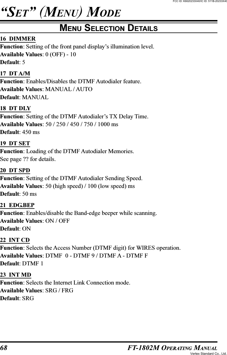

![70 FT-1802M OPERATING MANUAL“SET” (MENU) MODEMENU SELECTION DETAILS30 NM SETFunction: Programming an Alpha/Numeric label for a Memory Channel.See page ?? for details.31 OPN.MSGFunction: Selects the Opening Message that appears when the radio is powered on.Available Values: DC / MSG / OFFDefault: DCDC: DC supply voltageMSG: Set by user. See below.OFF: No Opening MessageHere’s how to program the Opening Message:1. Set this Set Mode Item to “MSG.”2. Press the [LOW(A/N)] key momentarily to enable programming of the opening mes-sage. You will notice the first character entry’s location blinking.3. Rotate the DIAL knob to select the first letter/number of the message, then press the[LOW(A/N)] key momentarily to save the first letter/number and move on to the nextcharacter.4. Repeat the previous step as necessary to complete the message (up to six characters).5. If you make a mistake, press the [DW(REV)] key to back-space the cursor; now re-enterthe correct letter/number.6. When you have entered the desired opening message, press the [MHz(SET)] key mo-mentarily to confirm the message, then press and hold in the [MHz(SET)] key for onesecond to save the settings and exit to normal operation.32 PAGERFunction: Enables/Disables the Enhanced CTCSS Paging & Code Squelch function.Available Values: ON / OFFDefault: OFF33 PAG.ABKFunction: Enables/Disables the Answer Back function of the Enhanced CTCSS Paging &Code Squelch function.Available Values: ON / OFFDefault: OFF34 PAG.CDRFunction: Setting the Receiver Pager Code for the Enhanced CTCSS Paging & Code Squelchfunction.See page ?? for details.FCC ID: K6620233X40/IC ID: 511B-20233X40Vertex Standard Co., Ltd.](https://usermanual.wiki/Yaesu-Musen/20233X40/User-Guide-601500-Page-72.png)
![71FT-1802M OPERATING MANUAL“SET” (MENU) MODEMENU SELECTION DETAILS35 PAG.CDTFunction: Setting the Transmitting Pager Code for the Enhanced CTCSS Paging & CodeSquelch function.See page ?? for details.36 PRG P1Function: Programming the function assigned to Microphone’s [P1] key.Available Values: ARTS / SQL OFF / WX CH / S SRCH / C SRCH / SCAN / T CALL orall Set mode items (except Set mode item #36 through 39).Default: Set mode item #13 DC VLT37 PRG P2Function: Programming the function assigned to Microphone’s [P2] key.Available Values: ARTS / SQL OFF / WX CH / S SRCH / C SRCH / SCAN / T CALL orall Set mode items (except Set mode item #36 through 39).Default: Set mode item #16 DIMMER38 PRG P3Function: Programming the function assigned to Microphone’s [P3] key.Available Values: ARTS / SQL OFF / WX CH / S SRCH / C SRCH / SCAN / T CALL orall Set mode items (except Set mode item #36 through 39).Default: Set mode item #27 MCGAIN39 PRG P4Function: Programming the function assigned to Microphone’s [P4] key.Available Values: ARTS / SQL OFF / WX CH / S SRCH / C SRCH / SCAN / T CALL orall Set mode items (except Set mode item #36 through 39).Default: Set mode item #47 SKIP40 PSWDFunction: Programs and activates the Password feature.Available Values: ON / OFFDefault: OFFFCC ID: K6620233X40/IC ID: 511B-20233X40Vertex Standard Co., Ltd.](https://usermanual.wiki/Yaesu-Musen/20233X40/User-Guide-601500-Page-73.png)