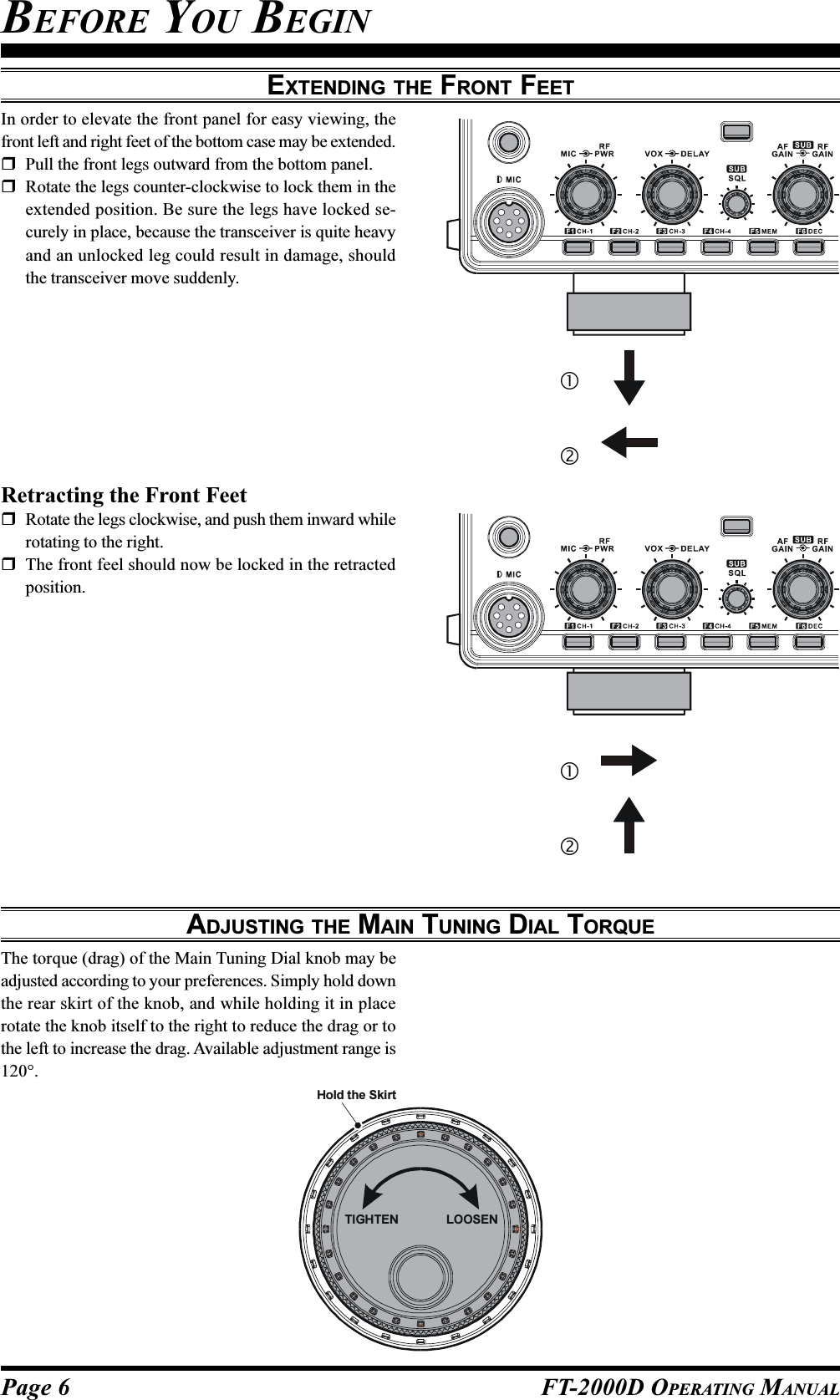
Yaesu Musen 20251X70 HF Transceiver with Scanning Receiver User Manual P65
Yaesu Musen Co., Ltd. HF Transceiver with Scanning Receiver P65
UserManual.wiki
>
Yaesu Musen
>
20251X70 User Manual
>
Users Manual 1
Contents
1.
Users Manual 1
2.
Users Manual 2
Users Manual 1
Navigation menu
Upload a User Manual
Namespaces
Wiki Guide
HTML
PDF
Info
Views
User Manual
Discussion / Help
Navigation


![Page 2 FT-2000D OPERATING MANUALTABLE OF CONTENTSGeneral Description ..................................................... 1Accessories & Options ................................................. 4Supplied Accessories ............................................... 4Available Options ..................................................... 4Before You Begin ......................................................... 6Extending the Front Feet .......................................... 6Adjusting the Main Tuning Dial Torque .................. 6Resetting the Microprocessor .................................. 7Resetting Memories (Only) ................................ 7Menu Resetting................................................... 7Full Reset ............................................................ 7Installation and Interconnections ............................... 8Antenna Considerations ........................................... 8About Coaxial Cable ................................................ 8Grounding ................................................................ 9Connection of Antenna and Power Cables ............. 10Connection of Microphone and Headphone .......... 11Key, Keyer, and Computer-Driven KeyingInterconnections ..................................................... 12VL-1000 Linear Amplifier Interconnections.......... 13Interfacing to Other Linear Amplifiers ................... 14Plug/Connector Pinout Diagrams ............................ 15Front Panel Controls & Switches ............................. 16Display Indications .................................................... 28Rear Panel .................................................................. 31FP-2000 Switches & Jacks ........................................ 34Basic Operation: Receiving on Amateur Bands ...... 35Operation on 60-Meter (5 MHz) Band(U.S. version only) ................................................. 38CLAR (Clarifier) Operation on Main (VFO-A) ..... 39LOCK ..................................................................... 40DIM ........................................................................ 40Convenience Features................................................ 42Dual Receive .......................................................... 42Using Headphones for Dual Receive ............... 43Sideband Diversity Reception .......................... 43Bandwidth Diversity Reception ....................... 44P.BACK (Audio Playback) fromMain (VFO-A) Receiver ........................................ 45P.BACK feature fromthe optional FH-2 Remote Control Keypad ..... 45“MY Bands” Operation .......................................... 46Band Stack Operation ............................................ 47C.S (Custom Switch) .............................................. 47Rotator Control Functions ...................................... 48More Frequency Navigation Techniques ............... 49Keyboard Frequency Entry .............................. 49Using the [SUB VFO-B] knob ......................... 49Using the UP/DOWN switches ofthe supplied MH-31B8 Hand Microphone ........ 49Receiver Operation (Front End Block Diagram) ... 50IPO (Intercept Point Optimization) ........................ 51ATT ........................................................................ 51RF Gain (SSB/CW/AM Modes) ............................ 52Advanced Interference-Suppression Features:RF Front End ............................................................. 53Using the VRF (Variable RF Front-end Filter) ...... 53Interference Rejection(Signals Off Frequency by Just a Few kHz) ............ 54R.FLT (Roofing Filters) ......................................... 54Interference Rejection (Signals within 3 kHz) ........ 55CONTOUR Control Operation .............................. 55IF SHIFT Operation ............................................... 56WIDTH (IF DSP Bandwidth) Tuning .................... 57Using IF Shift and Width Together................... 57IF Notch Filter Operation....................................... 58Digital Noise Reduction (DNR) Operation ............ 59Digital Notch Filter (DNF) Operation ................... 59NARROW (NAR) One-Touch IF Filter Selection . 60IF Noise Blanker (NB) Operation .......................... 61Tools for Comfortable and Effective Reception ...... 62AGC (Automatic Gain Control) ............................. 62SLOPED AGC Operation................................. 63Mute Feature (Main (VFO-A) Band) ..................... 63SSB/AM Mode Transmission .................................... 64Using the Automatic Antenna Tuner ........................ 66ATU Operation ....................................................... 66About ATU Operation ...................................... 67Lithium Battery Replacement ................................ 68Enhancing Transmit Signal Quality ......................... 69Adjusting the SSB Transmitted Bandwidth ........... 69Parametric Microphone Equalizer ......................... 70Using the Speech Processor ................................... 72Low- Distortion CLASS-A Operation .................... 74Transmitter Convenience Features .......................... 76Voice Memory ........................................................ 76Voice Memory Operation fromthe optional FH-2 Remote Control Keypad ..... 77VOX (Automatic TX/RX Switching using Voice Control) ............. 78MONITOR ............................................................. 78Split Operation Using the TX Clarifier .................. 79Split-Frequency Operation ..................................... 80VFO Tracking Feature ...................................... 80Quick Split Operation ....................................... 81CW Mode Operation ................................................. 82Setup for Straight Key(and Straight Key emulation) Operation ................ 82Using the Built-in Electronic Keyer ....................... 83Full Break-in (QSK) Operation ........................ 83Setting the Keyer Weight(Dot/Space:Dash) Ratio .................................... 84Selecting the Keyer Operating Mode ............... 84](https://usermanual.wiki/Yaesu-Musen/20251X70.Users-Manual-1/User-Guide-738937-Page-4.png)
![Page 7FT-2000D OPERATING MANUALRESETTING THE MICROPROCESSORRESETTING MEMORIES (ONLY)Use this procedure to reset (clear out) the Memory chan-nels previously stored, without affecting any configura-tion changes you may have made to the Menu settings.1. Press the front panel’s [POWER] switch to turn thetransceiver off.2. Press and hold in the [AM] button; while holding itin, press and hold in the front panel’s [POWER] switchto turn the transceiver on. Once the transceiver comeson, you may release the [AM] button.MENU RESETTINGUse this procedure to restore the Menu settings to theirfactory defaults, without affecting the memories you haveprogrammed.1. Press the front panel’s [POWER] switch to turn thetransceiver off.2. Press and hold in the [MENU] button; while holding itin, press and hold in the front panel’s [POWER] switchto turn the transceiver on. Once the transceiver comeson, you may release the [MENU] button.FULL RESETUse this procedure to restore all Menu and Memory set-tings to their original factory defaults. All Memories willbe cleared out by this procedure.1. Press the front panel’s [POWER] switch to turn thetransceiver off.2. Press and hold in the [FAST] and [LOCK] buttons;while holding them in, press and hold in the frontpanel’s [POWER] switch to turn the transceiver on.Once the transceiver comes on, you may release theother two switches.IMPORTANT NOTEWhen the optional DMU-2000 is connected and is turnedon the [POWER] switch, the DMU-2000’s data is alsoreset when perform the full reset of the FT-2000D.[POWER] button [AM] button[POWER] button [MENU] buttonBEFORE YOU BEGIN[POWER] button [LOCK] button[FAST] button](https://usermanual.wiki/Yaesu-Musen/20251X70.Users-Manual-1/User-Guide-738937-Page-9.png)

![Page 10 FT-2000D OPERATING MANUALANTENNA "1”ANTENNA "2”CONNECTION OF ANTENNA AND FP-2000 POWER SUPPLYPlease follow the outline in the illustration regarding the proper connection of antenna coaxial cables, as well as the FP-2000D Power Supply.ADVICE:Do not position this apparatus in a location with direct exposure to sunshine.Do not position this apparatus in a location exposed to dust and/or high humidity.Ensure adequate ventilation around this apparatus, so as to prevent heat build-up and possible reduction of performancedue to high heat.Do not install this apparatus in a mechanically-unstable location, or where objects may fall onto this product fromabove.To minimize the possibility of interference to home entertainment devices, take all precautionary steps including sepa-ration of TV/FM antennas from Amateur transmitting antennas to the greatest extent possible, and keep transmittingcoaxial cables separated from cables connected to home entertainment devices.Ensure that the AC power cord is not subject to undue stress or bending, which could damage the cable or cause it to beaccidentally unplugged from the rear panel AC input jack.Be absolutely certain to install your transmitting antenna(s) such that they cannot possibly come in contact with TV/FMradio or other antennas, nor with outside power or telephone lines.Use a short, thick, braided cableto connect your station equipmentto the buried ground rod (or alter-native earth ground system).INSTALLATION AND INTERCONNECTIONSNOTEPlease be sure that the FT-2000D’s [POWER]switch and the FP-2000’s [POWER] switch areboth turned off any time you plug in or unplug anypower cable to/from the FP-2000. This will avoidthe possibility of potentially-damaging spikes and/or electrical shock.](https://usermanual.wiki/Yaesu-Musen/20251X70.Users-Manual-1/User-Guide-738937-Page-12.png)
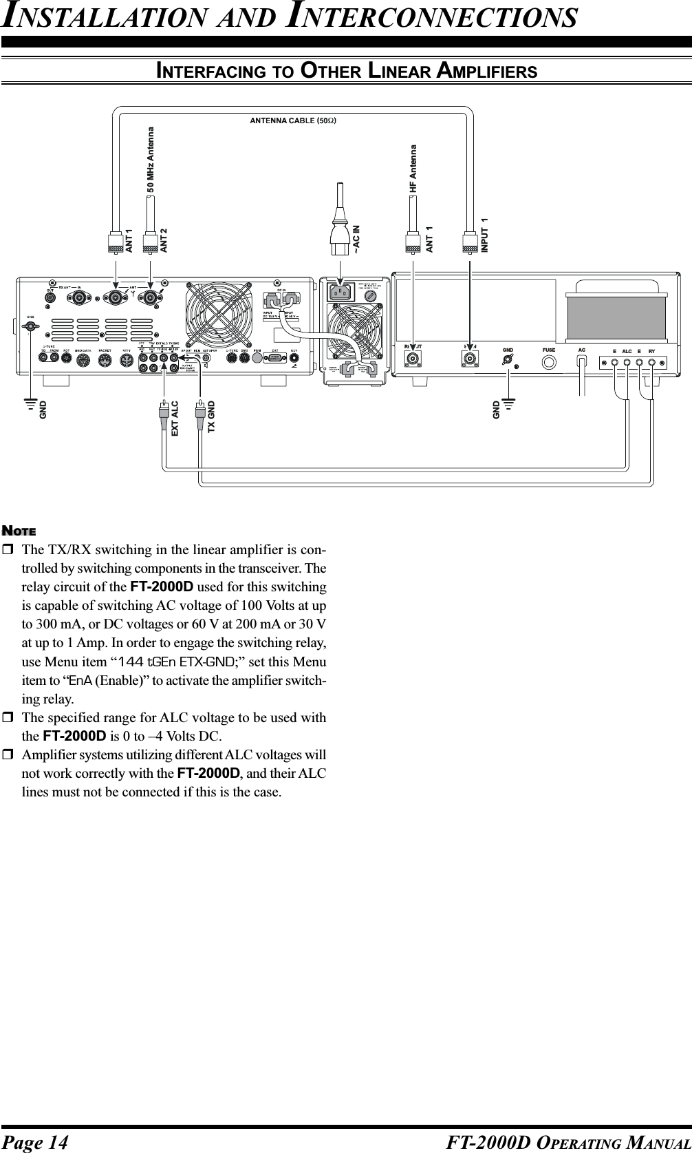
![Page 13FT-2000D OPERATING MANUALVL-1000 LINEAR AMPLIFIER INTERCONNECTIONSBe sure that both the FT-2000D and VL-1000 are turned off, then follow the installation recommendations contained inthe illustration.Please set the “ATT” switch to the “ON” position on the front panel of the VL-1000. The 200-Watt poweroutput from the FT-2000D is far in excess of what is required to drive the VL-1000 to its full rated output.NOTE:Please refer to the VL-1000 Operating Manual for details regarding amplifier operation.Please do not attempt to connect or disconnect coaxial cables when your hands are wet.INSTALLATION AND INTERCONNECTIONSTo link the FT-2000D and VL-1000 Powerswitches, set the VL-1000 REMOTE switch tothe “ON” position.About the CONTROL CableThe VL-1000 may be operated with the FT-2000D whether or not the CONTROL Cable isconnected; however, the CONTROL Cable al-lows you to tune up the amplifier automaticallyby just pressing the [F SET] or [TUNE] key onthe VL-1000, so as to transmit a carrier for tun-ing purposes.ANT 1ANT 2ANT 3ANT 4REMOTEONOFFBAND DATA 1BAND DATA 2GNDALC 2ALC 1PTT 2PTT 1INPUT 1INPUT 2CONTROLDC48V INANT 1~AC INANT 1HF Vertical AntennaHF Dipole AntennaHF Beam Antenna50 MHz AntennaANT 2ANT 3ANT 2INPUT 1TX REQEXT ALCBAND DATABAND-DATA 1BAND-DATA 2GNDDC 48V INCONTROLALC 1ALC CABLE (Supplied w/VL-1000)BAND DATA CABLE Supplied w/VL-1000 ()ANTENNA CABLE (Not Supplied) CONTROL CABLE (Supplied w/VL-1000)VP-1000VP-1000](https://usermanual.wiki/Yaesu-Musen/20251X70.Users-Manual-1/User-Guide-738937-Page-15.png)
![Page 16 FT-2000D OPERATING MANUALPOWER SwitchPress and hold in this switch for one second to turn thetransceiver on, after first setting the FP-2000’s[POWER] switch to the “I” position. Press and holdin this switch for one second, similarly, to turn the trans-ceiver off. If the FP-2000’s [POWER] switch is setto the “O” position, this switch will not function.ADVICE:The main power switch for the system is locatedon the front panel of the FP-2000 Power Supply.When the FP-2000 main power switch is pusheddown on the “I” side, the FP-2000 is turned on,and the FT-2000 is placed in the “standby” state.If the FP-2000 main power switch is not pressedin this manner, it is not possible to turn on the trans-ceiver. For more details about the main powerswitch location on the FP-2000, please see the dis-cussion on page 34.If you press this switch momentarily while the trans-ceiver is turned on, the transceiver’s audio will bemuted for three seconds.MOX SwitchPressing this button engages the PTT (Push to Talk)circuit, to activate the transmitter (the LED inside thisbutton will glow red). It must be turned off (the redLED will be off) for reception. This button replicatesthe action of the Push to Talk (PTT) switch on the mi-crophone. When engaging the [MOX] button (the LEDinside this button glows red) or otherwise causing atransmission to be started, be certain you have eitheran antenna or 50-Ohm dummy load connected to theselected Antenna jack.FRONT PANEL CONTROLS & SWITCHES](https://usermanual.wiki/Yaesu-Musen/20251X70.Users-Manual-1/User-Guide-738937-Page-18.png)
![Page 17FT-2000D OPERATING MANUALTUNE SwitchThis is the on/off switch for the FT-2000D’s Auto-matic Antenna Tuner.Pressing this button momentarily places the antennatuner in line between the transmitter final amplifier andthe antenna jack (“ ” icon will appear in the dis-play). Reception is not affected.Pressing and holding in this button for 1/2 second, whilereceiving in an amateur band, activates the transmitterfor a few seconds while the automatic antenna tunerrematches the antenna system impedance for minimumSWR. The resulting setting is automatically stored inone of the antenna tuner’s 100 memories, for instantautomatic recall later when the receiver is tuned nearthe same frequency.Pressing this button momentarily, while the Tuner isengaged, will take the Automatic Antenna tuner out ofthe transmit line.NOTE:When the Automatic Antenna Tuner is tuning itself, asignal is being transmitted. Therefore, be absolutelycertain that an antenna or dummy load is connected tothe selected antenna jack before pressing and holdingin the [TUNE] button to start antenna tuning.PHONES JackA 1/4-inch, 3-contact jack accepts either monaural orstereo headphones with 2- or 3-contact plugs. When aplug is inserted, the loudspeaker is disabled. With ste-reo headphones such as the optional YH-77STA, youcan monitor both Main (VFO-A) and Sub (VFO-B)receiver channels at the same time during Dual Re-ceive operation.NOTE:When wearing headphones, we recommend that youturn the AF Gain levels down to their lowest settingsbefore turning power on, to minimize the impact onyour hearing caused by audio “pops” during switch-on.KEY JackThis 1/4-inch, 3-contact jack accepts a CW key or keyerpaddles (for the built-in electronic keyer), or outputfrom an external electronic keyer. Pinout is shown onpage 15. Key up voltage is 5 V, and key down currentis 1 mA. This jack may be configured for keyer, “Bug,”“straight key,” or computer keying interface operationvia Menu item “052 A1A F-TYPE” (see page 121).There is another jack with the same name on the rearpanel, and it may be configured independently for In-ternal Keyer or pseudo-straight-key operation.NOTE:You cannot use a 2-contact plug in this jack (to do soproduces a constant “key down” condition).Microphone ConnectorThis 8-pin jack accepts input from a microphone uti-lizing a traditional YAESU HF-transceiver pinout.DIM SwitchPress this button to lower the illumination intensity ofthe analog meter and the frequency display. Press itonce more to restore full brightness.ADVICE:Menu Items “008 diSP DIM MTR” and “009 diSPDIM VFD” allow you to configure the dimming levelsfor the analog meter and the frequency display inde-pendently, so you can customize the brightness levels.VOX SwitchThis button enables automatic voice-actuated transmit-ter switching in the SSB, AM, and FM modes. Whileactivated, the LED inside this button glows red. Thecontrols affecting VOX operation are the front panel’s[VOX] and [DELAY] knobs. By proper adjustment ofthese controls, hands-free voice-actuated operation ispossible.ANTENNA Select Switch[1/2]: Pressing this selects either the ANT 1 or 2 jackon the rear panel, and allows convenient antennaswitching at the press of button. The selected antennajack is indicated at the upper left corner of the display.[RX]: Normally, the antenna connected to the ANT 1or 2 jack is used for receive (and always used for trans-mit). When the [RX] switch is pressed, an antenna con-nected to the RX ANT will be used during receive.MONI (Monitor) SwitchThis button enables the transmit monitor in all modes.While activated, the “ ” icon appears in the dis-play. Adjustment of the Monitor level is accomplishedusing the [MONI] knob.ADVICE:When using headphones, the Monitor is highly usefulfor making adjustments to the Parametric Equalizer orother voice quality adjustments, because the voice qual-ity heard in the headphones is such a “natural” repro-duction of the transmitted audio quality.FRONT PANEL CONTROLS & SWITCHES](https://usermanual.wiki/Yaesu-Musen/20251X70.Users-Manual-1/User-Guide-738937-Page-19.png)
![Page 18 FT-2000D OPERATING MANUALFRONT PANEL CONTROLS & SWITCHESPROC (Processor) SwitchThis button enables the Parametric Microphone Equal-izer and Speech Processor for SSB/AM transmission.While activated the Parametric Microphone Equalizer,the “ ” icon appears in the display.While activated the Speech Processor, the “ ”and “ ” icons appears in the display. Adjustmentof the Processor level is accomplished using the[PROC] knob.ADVICE:The Speech Processor is a tool for increasing theaverage power output through a compression tech-nique. However, if the [PROC] knob is advancedtoo far, the increase in compression becomescounter-productive, as intelligibility will suffer. Werecommend that you monitor the sound of your sig-nal using the Monitor (with headphones).When the optional DMU-2000 Data ManagementUnit is connected, you may use the Audio Scope/Oscilloscope page to help you adjust the setting ofthe compression level of the Speech Processor foroptimum performance using your voice and micro-phone.KEYER SwitchThis button toggles the internal CW keyer on and off.While activated, the “ ” icon appears in the dis-play. The Keyer sending speed and the CW Hang Timeare adjusted via the front panel’s [SPEED] and [DE-LAY] knobs.ATT SwitchThis button selects the degree of attenuation, if any, tobe applied to the receiver input.Available selections are –6 dB, –12 dB, –18 dB, orOFF, and the selected attenuation level appears in theATT column of the Receiver Configuration Indicatoron the display.ADVICE:The Attenuator affects both the Main (VFO-A) andSub (VFO-B) receivers.The Attenuator may be used in conjunction withthe [IPO] switch to provide two stages of signalreduction when an extremely strong signal is beingreceived.](https://usermanual.wiki/Yaesu-Musen/20251X70.Users-Manual-1/User-Guide-738937-Page-20.png)
![Page 19FT-2000D OPERATING MANUALFRONT PANEL CONTROLS & SWITCHESIPO (INTERCEPT POINT OPTIMIZATION) SwitchThis button may be used to set the optimum front endcharacteristics of the receiver circuit for a very strong-signal environment. Available selections are AMP 1(low distortion amplifier), AMP 2 (2-stage low-distor-tion RF amplifier), or ON (bypasses the front end RFamplifier), and the selected receiver RF amplifier ap-pears at the IPO column of the Receiver ConfigurationIndicator in the display.ADVICE:The IPO switch affects both the Main (VFO-A) andSub (VFO-B) receivers.R.FLT SwitchThis button selects the bandwidth for the Main Band(VFO-A) receiver’s first IF Roofing Filter. Availableselections are 3 kHz, 6 kHz, 15 kHz, or Auto, and theselected bandwidth appears in the FLT column of theReceiver Configuration Indicator on the display.ADVICE:The Roofing Filter selection applies to the Mainband (VFO-A) only.Because the roofing filter is in the first IF, the pro-tection it provides against interference is quite sig-nificant. When set to AUTO, the SSB bandwidth is6 kHz, while CW is 3 kHz and FM/RTTY are 15kHz. On a crowded SSB band, however, you maywish to select the 3 kHz filter, for the maximumpossible interference rejection.AGC SwitchThis button selects the AGC characteristics for the re-ceiver. Available selections are FAST, MID, SLOW,or AUTO, and the “AGC” icon will change accordingto the AGC characteristics selected.Press the [AGC] button repeatedly to select the de-sired receiver-recovery time constant. Press and holdin the [AGC] button for two seconds to disable theAGC (for testing or weak-signal reception).When the [AGC] button is pressed independently, itapplies to the Main band (VFO-A) receiver.When you press the [B] button, followed by the [AGC]button (within five seconds of pressing the [B] switch),it affects the Sub band (VFO-B) receiver.ADVICE:If the AGC receiver-recovery time is set to “Off” bypressing and holding in the [AGC] button, the S-meterwill no longer deflect. Additionally, you will likely en-counter distortion on stronger signals, as the IF ampli-fiers and the following stages are probably being over-loaded.NB SwitchThis button turns the IF Noise Blanker on and off.Press this button momentarily to reduce a short-dura-tion pulse noise; the “ ” icon will appear in the dis-play.Press and hold in this button for one second to reducea longer-duration man-made pulse noise; the “ ”icon will blink for three seconds, then will appear con-tinuously in the display.Press this button again to disable the noise blanker;the “ ” icon will disappear.ADVICE:When you press (or press and hold) the [NB] buttonmomentarily, it affects the Main band (VFO-A) re-ceiver. When you press the [B] button, then press (orpress and hold in) the [NB] button (within five sec-onds of pressing the [B] button), it affects the Sub band(VFO-B) receiver.METER SwitchThis control switch determines the function of the meterduring transmission.COMP: Indicates the speech compressor level (SSBmode only).ALC: Indicates the relative ALC voltage.PO: Indicates the power output level.SWR: Indicates the Standing Wave Ratio (Forward:Reflected).ID: Indicates the final amplifier drain current.VDD: Indicates the final amplifier drain voltage.MONI PROC KnobsMONI KnobThe inner [MONI] knob adjust the audio level of thetransmit RF monitor during transmission (relative tothe AF GAIN control), when activated by the [MONI]button.PROC KnobThe outer [PROC] knob sets the compression (input)level of the transmitter RF Speech Processor in the SSBand AM modes, when activated by the [PROC] but-ton.BK-IN SwitchThis button turns the CW break-in capability on andoff. While the CW break-in is activated, the “ ”icon appears in the display.SPOT SwitchThis button turns on the CW receiver spotting tone; bymatching the SPOT tone to that of the incoming CWsignal (precisely the same pitch), you will be “zerobeating” your transmitted signal on to the frequency ofthe other station.The Sub (VFO-B) frequency display will indicate theoffset tone frequency when this button is pressed.](https://usermanual.wiki/Yaesu-Musen/20251X70.Users-Manual-1/User-Guide-738937-Page-21.png)
![Page 20 FT-2000D OPERATING MANUALFRONT PANEL CONTROLS & SWITCHESSPEED PITCH KnobsSPEED KnobThe inner [SPEED] knob adjusts the keying speed ofthe internal CW keyer (4 ~ 60 WPM). Clockwise rota-tion increases the sending speed.When turning this knob while pressing the [KEYER]button, the Sub (VFO-B) frequency display shows thekeying speed.PITCH KnobThe outer [PITCH] knob selects your preferred CWtone pitch (from 300 ~ 1050 Hz, in 50 Hz increments).The Tx sidetone, receiver IF passband, and displayoffset from the BFO (carrier) frequency are all affectedsimultaneously. The Pitch control setting also affectsthe operation of the CW Tuning Indicator, as the cen-ter frequency of the CW Tuning Indicator will followthe setting of this control.NB SQL KnobsNB KnobThe inner [NB] knob adjusts the noise blanking levelwhen the (analog) IF noise blanker is activated by press-ing the [NB] button.SQL KnobThe outer [SQL] knob sets the signal level thresholdat which the Main (VFO-A) receiver audio is muted,in all modes. It is very useful during local rag-chews,to eliminate noise between incoming transmissions.This control is normally kept fully counter-clockwise(off), except when scanning and during FM operation.](https://usermanual.wiki/Yaesu-Musen/20251X70.Users-Manual-1/User-Guide-738937-Page-22.png)
![Page 21FT-2000D OPERATING MANUALFRONT PANEL CONTROLS & SWITCHESMIC RF PWR KnobsMIC KnobThe inner [MIC] knob adjusts the microphone inputlevel for (non-processed) SSB transmission.ADVICE:If you adjust the MIC Gain while speaking in a some-what-louder-than-normal voice level, watch the ALClevel and adjust the MIC Gain so that the ALC reachesjust to the right edge of the ALC scale. Then, whenyou speak in a more normal voice level, you’ll be cer-tain not to be over-driving the mic amplifier stage.RF PWR KnobThe outer [RF PWR] knob is the main RF Power out-put control for the transceiver, active in all operatingmodes. Clockwise rotation increases the power out-put. Adjust this control for the desired power outputfrom the FT-2000D.VOX DELAY KnobsVOX KnobThe inner [VOX] knob sets the gain of the VOX cir-cuit, to set the level of microphone audio needed toactivate the transmitter during voice operation whilethe [VOX] switch is engaged. The [VOX] switch mustbe switched “ON” to engage the VOX circuit.DELAY KnobThe outer [DELAY] knob sets the hang time of theVOX circuit for voice operation and keying delay forCW operation.During voice operation, this knob sets the hang time,between the moment you stop speaking, and the auto-matic switch from transmit back to receive. Adjust thisfor smooth VOX operation, so the receiver is only ac-tivated when your transmission is ended and you wishto receive.For CW operation, this knob sets the keying delay,between the moment you stop sending, and the auto-matic switch from transmit back to receive during“Semi-break-in” operation. Adjust this just long enoughto prevent the receiver from being restored during wordspaces at your preferred sending speed.SUB SQL KnobThis knob sets the signal level threshold at which Sub(VFO-B) receiver audio is muted, in all modes. It isvery useful during local rag-chews, to eliminate noisebetween incoming transmissions. This control is nor-mally kept fully counter-clockwise (off), except whenscanning and during FM operation.SUB AF GAIN SUB RF GAINAF GAIN KnobThe inner [SUB AF GAIN] knob sets the Sub (VFO-B) receiver’s audio volume level. Typically, you willoperate with this control set between the 9 o’clock and10 o’clock positions.RF GAIN KnobThe outer [SUB RF GAIN] knob is the Sub (VFO-B)receiver’s RF gain control, which adjusts the gain ofthe Sub (VFO-B) receiver’s RF and IF amplifier stages.This control is normally left in the fully clockwise po-sition.AF GAIN RF GAIN KnobsAF GAIN KnobThe inner [AF GAIN] knob sets the Main (VFO-A)receiver’s audio volume level. Typically, you will op-erate with this control set between the 9 o’clock and10 o’clock positions.RF GAIN KnobThe outer [RF GAIN] knob is the Main (VFO-A)receiver’s RF gain control, which adjusts the gain ofthe Main (VFO-A) receiver’s RF and IF amplifierstages. This control is normally left in the fully clock-wise position.MODE Switches[A], [B] SwitchPressing the [A] or [B] button will illuminate the re-spective indicator imbedded within the switch, allow-ing adjustment of the operating mode on the Main(VFO-A) or Sub (VFO-B) band. Usually, the [A] but-ton glow Red, signifying that the Main band (VFO-A)is being adjusted. Similarly, pressing the [B] buttonwill cause its indicator to blink Orange for five sec-onds, signifying Sub band (VFO-B) adjustment.ADVICE:When changing bands, confirm the [A] or [B] buttonillumination status at first, then press the appropriate[BAND] button, so as to change operating frequencieson the proper (Main or Sub) band.[LSB], [USB], [CW], [AM/FM], [RTTY], [PKT] SwitchPressing the [LSB], [USB], [CW], [AM/FM],[RTTY], or [PKT] button will select the operatingmode. Pressing the [CW], [AM/FM], [RTTY], or[PKT] button multiple times will switch between thealternate operating features that can be used on thesemodes (covered later).](https://usermanual.wiki/Yaesu-Musen/20251X70.Users-Manual-1/User-Guide-738937-Page-23.png)
![Page 22 FT-2000D OPERATING MANUALFRONT PANEL CONTROLS & SWITCHESF1 - F7 / DISPLAY KeysThese keys can be used to control the Voice Memorycapability for the SSB/AM/FM modes, and the Con-test Keyer for the CW mode. You can also play backup to 15 seconds of incoming received audio, as well,for verification of a missed callsign or other purposes.When the optional DMU-2000 Data Management Unitis connected, you can also use the “Function” keys forthe various functions associated with each “page” ofthe external display’s capability.[F1(CH 1)] - [F4(CH 4)] keyIn the case of Voice Memory, up to 20 seconds of au-dio may be stored on each channel. For CW messages,up to 50 characters (“PARIS” specification) may bestored into each channel. See page 76 (Voice Memory)or page 88 (Contest Keyer) for details.[F5(MEM)] keyThis key is pressed for the purpose of storing either aVoice Memory or a Contest Keyer Memory channel’scontents. See page 76 (Voice Memory) or page 88(Contest Keyer) for details.[F6(DEC)] keyWhen utilizing the sequential contest number capabilityof the Contest Keyer, press this key to decrement (backup) the current Contest Number by one digit (i.e. to backup from #198 to #197, etc.). See page 91 for details.[F7(P.BACK)] keyPress and hold in this button for 2 seconds to activatethe recording feature of the internal Digital Voice Re-corder. The Voice Recorder allows you to record theMain band (VFO-A) receiver audio for the most-re-cent 15 seconds. While you’re recording the receiveraudio, the “ ” icon will appear in the display.Press this button momentarily to stop the recording,then press this button momentarily again to play backthe receiver audio for the most-recent 15 seconds ofreception before you stopped the recording.While playing back the receiver audio, the “ ” iconwill appear in the display.Press and hold in this button for 2 seconds again toresume recording.[DISPLAY] keyPress and hold in this key for two seconds to cause the[F1(CH 1)] - [DISPLAY] keys to act as “Function”keys for the optional DMU-2000 Data ManagementUnit if connected.](https://usermanual.wiki/Yaesu-Musen/20251X70.Users-Manual-1/User-Guide-738937-Page-24.png)
![Page 23FT-2000D OPERATING MANUALFRONT PANEL CONTROLS & SWITCHESQMB (Quick Memory Bank) SwitchesSTO (Store) ButtonPressing this button copies operating information (fre-quency, mode, bandwidth, and also repeater direction/shift frequency and CTCSS functions on the FM mode)into consecutive QMB Memories.RCL (Recall) ButtonPressing this button recalls one of up to five QuickMemory Bank memories for operation.NAR (Narrow) SwitchIn the SSB/CW modes on the Main band (VFO-A), thisbutton is used to set the bandwidth of the DSP (digital)IF filters to a user-programmed bandwidth (defaultvalues are SSB: 1.8 kHz and CW/RTTY/PSK: 300 Hz).ADVICE:When [NAR] has been engaged, the [WIDTH] knobwill be disabled, although the [SHIFT] knob still worksnormally.In the SSB/CW modes on the Sub Band (VFO-B), thisbutton is used to toggle the receiver’s bandwidth be-tween wide (2.4 kHz) and narrow (1.0 kHz).ADVICE:When the Sub Band’s (VFO-B) optional YF-122C (500Hz) or YF-122CN (300 Hz) CW narrow filter is in-stalled, the optional narrow filter will be activated whenthe [NAR] switch has been engaged on the CW/RTTY/PSK modes.In the AM mode, this button is used to toggle thereceiver’s bandwidth between wide (9 kHz) and nar-row (6 kHz).In the FM mode on the 28 MHz and 50 MHz bands,this button is used to toggle the FM deviation/band-width between wide (±5.0 kHz Dev./25.0 kHz BW)and narrow (±2.5 kHz Dev./12.5 kHz BW).Pressing the [A] or [B] button (located above the[MODE] selection buttons) will select either the Mainband (VFO-A) or Sub band (VFO-B) for individualbandwidth setting.SPLIT SwitchPressing this button to activate split frequency opera-tion between the Main band (VFO-A), used for recep-tion, and the Sub band (VFO-B), used for transmis-sion. If you press and hold in the [SPLIT] button fortwo seconds, the “Quick Split” feature will be engaged,whereby the Sub band VFO (VFO-B) will automati-cally be set to a frequency 5 kHz higher than the Mainband (VFO-A) frequency with same operating mode,and the transceiver will be placed in the Split mode.TXW “TX Watch” SwitchPressing this button lets you monitor the transmit fre-quency when split frequency operation is engaged.Release the button to return to normal operation.C.S SwitchPress this button momentarily to recall a favorite MenuSelection directly.To program a Menu selection as the short-cut, pressthe [MENU] button to enter the Menu, then select theMenu item you want to set as the short-cut. Now pressand hold in the [C.S] button for two seconds; this willlock in the selected Menu item as the short-cut.RX Indicator/SwitchThis button, when pressed, engages the Main band(VFO-A) receiver; the LED inside this button will glowGreen when the Main receiver is active.When the Main (VFO-A) receiver is active, pressingthis button momentarily will mute the receiver, and theindicator will blink. Pressing the button once more willrestore receiver operation, and the indicator will glowGreen steadily.TX Indicator/SwitchWhen this button is pushed, the LED inside this buttonwill glow Red, and the transmitter will be engaged onthe same frequency and mode as set up for the Mainband (VFO-A) (subject to any Clarifier offset, ofcourse).ADVICE:If this indicator is not illuminated, it means that theSub (VFO-B) TX indicator has been selected (it willbe glowing Red). In this case, transmission will be ef-fected on the frequency and mode programmed for theSub (VFO-B) band.Main Tuning Dial KnobThis large knob adjusts the operating frequency of theMain band (VFO-A) or a recalled memory. Clockwiserotation of this knob increases the frequency. Defaulttuning increments are 10 Hz (100 Hz in AM and FMmodes); when the [FAST] button is pressed, the tun-ing steps increase. The available steps are:OPERATING MODELSB/USB/CW/RTTY/PKT(LSB)AM/FM/PKT(FM)Numbers in parentheses indicate steps when the [FAST] button is On.1 STEP10 Hz (100 Hz)100 Hz (1 kHz)1 DIAL ROTATION10 kHz (100 kHz)100 kHz (1 MHz)ADVICE:The tuning steps for the Main Tuning Dial knob areset, at the factory, to 10 Hz per step. Via Menu item“116 tun DIALSTP,” however, you may change thissetting from 10 Hz to 1 Hz instead. When 1 Hz basicsteps are selected, the action of the [FAST] button willbe changed to 1/10 of the values listed above.FAST SwitchPressing this button will increase or decrease the tun-ing rate of the Main Tuning Dial knob by a factor often, as mentioned in the previous section.When this function is activated, the “ ” icon ap-pears in the display.](https://usermanual.wiki/Yaesu-Musen/20251X70.Users-Manual-1/User-Guide-738937-Page-25.png)
![Page 24 FT-2000D OPERATING MANUAL+CLARLOCK SwitchThis button toggles locking of the Main Tuning Dialknob, to prevent accidental frequency changes. Whenthe button is active, the Main Tuning Dial knob canstill be turned, but the frequency will not change, andthe “ ” icon appears in the display.[AB] SwitchPress this button momentarily to transfer data from theMain band (VFO-A) frequency (or a recalled memorychannel) to the Sub band (VFO-B), overwriting anyprevious contents in the Sub band (VFO-B). Use thiskey to set both Main band (VFO-A) and Sub band(VFO-B) receivers to the same frequency and mode.[AB] SwitchPressing this button momentarily exchanges the con-tents of the Main band (VFO-A) (or a recalled memorychannel) and the Sub band (VFO-B).[V/M] SwitchThis button toggles Main band (VFO-A) receiver op-eration between the memory system and the VFO. Ei-ther “ ” or “ ” will be displayed to the underthe main frequency display field to indicate the cur-rent selection. If you have tuned off of a Memory chan-nel frequency (MT), pressing this button returns thedisplay to the original memory contents (MR), andpressing it once more returns operation to the MainVFO (no icon).[MA] SwitchPressing this button momentarily displays the contentsof the currently-selected memory channel for three sec-onds.Holding this button in for 2 seconds copies the datafrom the currently-selected memory to the Main VFO(VFO-A), as two beeps sound. Previous data in theMain VFO will be overwritten.FRONT PANEL CONTROLS & SWITCHES](https://usermanual.wiki/Yaesu-Musen/20251X70.Users-Manual-1/User-Guide-738937-Page-26.png)
![Page 25FT-2000D OPERATING MANUAL[AM] SwitchPressing and holding in this key for 1/2 second (untilthe double beep) copies the current operating data fromthe Main band (VFO-A) into the currently selectedmemory channel, overwriting any previous data storedthere.Also, pressing and holding in this button after recall-ing a memory, without first retuning, causes the memorychannel to be “masked,” and repeating the process re-stores the masked memory.MENU SwitchThis button is used for gaining access to the Menu sys-tem, for configuring various transceiver characteris-tics. Menu operation is described in detail, in thismanual, beginning on page 112.IMPORTANT NOTE:Pressing this button momentarily activates the Menu,and the Menu items will appear on the display; onceyou are finished, you must press and hold in the[MENU] button for two seconds to save any configu-ration changes (momentarily pressing the [MENU]button to exit will not save the changes).BAND KeysThese keys allow one-touch selection of the desiredAmateur band (1.8 ~ 50 MHz).What’s more, these keys may be used for direct entryof a desired operating frequency during VFO opera-tion.RX CLAR SwitchPressing this button activates the RX Clarifier, to al-low offsetting the Main (VFO-A) receiving frequencytemporarily. Press this button once more to return theMain receiver to the frequency shown on the main fre-quency display field; the Clarifier offset will still bepresent, though, in case you want to use it again. Tocancel the Clarifier offset, press the [CLEAR] button.TX CLAR SwitchPressing this button activates the TX Clarifier, to al-low offsetting the Main (VFO-A) transmit frequencytemporarily.Press this button once more to return the transmitter tothe Main (VFO-A) frequency shown on the main fre-quency display field; the Clarifier offset will still bepresent, though, in case you want to use it again. Tocancel the Clarifier offset, press the [CLEAR] button.CLEAR SwitchPressing this button clears out any frequency offset youhave programmed into the Clarifier register (therebysetting the offset to “Zero”).CLAR KnobThis knob tunes the Clarifier offset frequency up to9.99 kHz.VRF KnobThis knob tunes the passband of the VRF (Variable RFFilter) preselector circuit for maximum receiver sensi-tivity (and out-of-band interference rejection).ADVICE:The relative position of the VRF passband can beobserved on the Tuning Offset Indicator of the dis-play via Menu item “010 diSP BAR SEL.”When the optional RF µTuning Kit is connected,this knob allows adjustment of the center frequencyof the µ-Tuning filter passband (which is muchnarrower than that of the VRF).VRF SwitchThis button turns the VRF filter on and off. While ac-tivated, the “ ” icon will appear in the FLT columnof the Receiver Configuration Indicator on the display.ADVICE:When the optional RF µTuning Kit is connected, press-ing this button will engage the µ-Tuning filter. TheµTuning Kit provides much better RF selectivity thanany other RF filter in the Amateur industry, yieldingoutstanding protection from high RF levels not far re-moved from the current operating frequency.NOTCH SwitchThis button turns the Main band (VFO-A) receiver’sIF Notch Filter on and off.When the IF Notch Filter is activated, the peak posi-tion of the IF Notch Filter is depicted graphically inthe display. The IF Notch Filter center frequency isadjusted via the [NOTCH] knob.DNF SwitchThis button turns the Main band (VFO-A) receiver’sDigital Notch Filter on and off. When the Digital NotchFilter is activated, the “ ” icon appears in the dis-play. This is an automatic circuit, and there is no ad-justment knob for the DNF.NOTCH KnobThis knob adjusts the center frequency of the Mainband (VFO-A) receiver’s IF Notch Filter. The NotchFilter is engaged via the [NOTCH] button.Initially, the approximate center frequency of the IFNotch Filter is adjusted by the outer [COARSE] knob;then, fine tuning of the center frequency is adjusted bythe inner [FINE] knob.FRONT PANEL CONTROLS & SWITCHES](https://usermanual.wiki/Yaesu-Musen/20251X70.Users-Manual-1/User-Guide-738937-Page-27.png)
![Page 26 FT-2000D OPERATING MANUAL+CLARSHIFT WIDTH Knobs (EXCEPT ON FM MODE)SHIFT KnobThe inner [SHIFT] knob provides adjustment of theIF DSP passband, using 20 Hz steps for precise ad-justment and easy reduction of interference on eitherside of your operating frequency. The total adjustmentrange is ±1 kHz. The normal operating setting for thisknob is straight up, in the 12 o’clock position.ADVICE:You may shift the Sub band (VFO-B) filter passbandvia Menu item “042 S-iF LSB SET” through “049 S-iF PKT-USB.”WIDTH KnobThe outer [WIDTH] knob sets the overall bandwidthof the IF DSP filter for the Main (VFO-A) receiver.The center (12 o’clock) position establishes the “de-fault” bandwidth (for example, 2.4 kHz for SSB);clockwise rotation of this knob increases the bandwidth(out to a maximum of 4 kHz), while counter-clock-wise rotation reduces the bandwidth.When the NAR (Narrow) filter selection is engaged,the [WIDTH] knob is disabled.The [SHIFT] knob may be used to re-center the pass-band response on the incoming signal, and you mayfind that the CONTOUR and IF Notch Filter may alsohelp improve intelligibility and/or reduce interference.See also the discussions of the [CONTOUR] knob and[NOTCH] knob.ADVICE:When the [NAR] button has been pushed, the [WIDTH]knob no longer functions. The IF SHIFT system is stillfully operational, however.FRONT PANEL CONTROLS & SWITCHES](https://usermanual.wiki/Yaesu-Musen/20251X70.Users-Manual-1/User-Guide-738937-Page-28.png)
![Page 27FT-2000D OPERATING MANUALCONT SwitchThis button turns the Main band (VFO-A) receiver’sCONTOUR filter on and off. When the CONTOURFilter is activated, the peak position of the CONTOURFilter is depicted graphically in the display. Adjustmentof the CONTOUR filter’s center frequency is providedby the [CONTOUR] knob.NOTE:There are times, when you’re trying to remove inter-ference with a sharp DSP filter, that the remaining sig-nal has a somewhat unnatural sound. This is caused bythe cutting of some frequency components, leavingother components in excess. The CONTOUR filter al-lows you (especially) to roll off certain frequency com-ponents inside the remaining passband, but in a smoothmanner that helps restore a natural sound and/or raiseintelligibility.DNR SwitchThis button turns the Main band (VFO-A) receiver’sDigital Noise Reduction circuit on and off. When theDigital Noise Reduction is activated, the “ ” iconappears in the display. Adjustment of the Noise Re-duction level is provided by the [DNR] knob.CONTOUR DNR KnobCONTOUR KnobThe inner [CONTOUR] knob selects the desired Mainband (VFO-A) receiver’s CONTOUR filter response.The CONTOUR filter is engaged via the [CONTOUR]button.DNR KnobThe outer [DNR] knob selects the Main band (VFO-A) receiver’s optimum Digital Noise Reduction re-sponse. The Noise Reduction circuit is engaged viathe [DNR] button.RX Indicator/SwitchThis is the button that turns the Sub (VFO-B) receiverOn and Off. When this button is pressed to make theSub (VFO-B) receiver active, the Green LED imbed-ded within the button will light up. Pressing the buttonagain will disable this receiver, and the imbedded GreenLED will turn off.TX Indicator/SwitchThis is the button that turns the Sub (VFO-B) trans-mitter On and Off. When this button is pressed to trans-fer transmitter control to the Sub (VFO-B) frequencyand mode, the Red LED imbedded within the buttonwill light up. Pressing this button once more will trans-fer frequency/mode control back to the Main (VFO-A) side, and the Red LED imbedded within this buttonwill turn off.SUB VFO-B KnobDepending on the status of the [A/B] button located atthe right bottom of the [SUB VFO-B] knob, the [SUBVFO-B] knob is used for functions associated with theMain (VFO-A) or Sub (VFO-B) frequency control reg-isters.(VFO-A) BAND SwitchPressing this button allows you to select the Main(VFO-A) operating band (Amateur bands) using the[SUB VFO-B] knob.(VFO-A) MHz SwitchPressing this button allows you to tune the Main band(VFO-A) frequency down or up in 1 MHz increments,using the [SUB VFO-B] knob.GRP SwitchPressing this button allows you to select the memorygroup using the [SUB VFO-B] knob.M CH SwitchPressing this button allows you to select the memorychannel using the [SUB VFO-B] knob.(VFO-B) BAND SwitchWhen the [A/B] button is pressed, and the Orange lampto the right of the [SUB VFO-B] knob lights up, press-ing this button allows you to select the Sub (VFO-B)operating band (Amateur bands) using the [SUB VFO-B] knob.(VFO-B) MHz SwitchWhen the [A/B] button is pressed, and the Orange lampto the right of the [SUB VFO-B] knob lights up, press-ing this button allows you to tune the Sub band (VFO-B) frequency down or up in 1 MHz increments, usingthe [SUB VFO-B] knob.FAST SwitchWhen the [A/B] button is pushed, and the Orange lampto the right of the [SUB VFO-B] knob lights up, the[SUB VFO-B] knob will be controlling the Sub band(VFO-B) frequency; pressing the [FAST] button willincrease the tuning rate by a factor of 10.A/B SwitchThe [A/B] button determines whether the actions ofthe [SUB VFO-B] knob will be applied to the Mainband (VFO-A) or the Sub band (VFO-B).Pressing this button once causes the Orange lamp tothe right of the [SUB VFO-B] knob to light up; in thiscase, rotation of the [SUB VFO-B] knob affects op-eration on the Sub band (VFO-B). Pressing the [A/B]button once more causes the Orange lamp to turn off;in this instance, rotation of the [SUB VFO-B] knobaffects operations associated with the Main band (VFO-A).FRONT PANEL CONTROLS & SWITCHES](https://usermanual.wiki/Yaesu-Musen/20251X70.Users-Manual-1/User-Guide-738937-Page-29.png)
![Page 28 FT-2000D OPERATING MANUALReceiver Configuration IndicatorsANT (1, 2, RX):Indicates the antenna selected for operation by the frontpanel [1/2] and [RX] antenna switches.ATT (OFF, –6 dB, –12 dB, –18 dB):Indicates the attenuation level selected for operationby the front panel [ATT] button.FLT (VRF, µ-TUNE, THRU):Indicates the RF filter selected for operation by thefront panel [VRF] button.ADVICE:The µ-TUNE filter is an option. The “ ” icon willnot appear when the optional µ-TUNE unit is not con-nected.IPO (AMP 1, AMP 2, ON):Indicates the front end RF amplifier selected for op-eration by the front panel [IPO] button.R.FLTIndicates the 1st IF Roofing Filter selected: AUTO(mode-determined), 3 kHz, 6 kHz, or 15 kHz.AGC (AUTO, FAST, MID, SLOW):Indicates the AGC decay time selected for Main band(VFO-A) operation by the front panel [AGC] switch.DNRThis indicator appears whenever the Digital Noise Re-duction feature is activated.DNFThis indicator appears whenever the Digital Notch Fil-ter is activated.CONTOURThe peak position of the CONTOUR Filter is depictedgraphically here when the CONTOUR Filter is acti-vated.NOTCHThe null position of the IF Notch Filter is depictedgraphically here when the IF Notch Filter is activated.WIDTHIndicates the bandwidth of the DSP IF filter.SHIFTIndicates the peak position of the DSP IF filter.NBThis indicator appears when the Main band (VFO-A)receiver’s (short duration) Noise Blanker is activated.This indicator will blink for three seconds, and there-after appears continuously, when the Main band (VFO-A) receiver’s longer-pulse Noise Blanker is activated.NARThis indicator appears whenever the Main band (VFO-A) receiver’s narrow IF DSP filter is engaged.PROCThis indicator appears whenever the DSP Speech Pro-cessor is activated.MONIThis indicator appears whenever the transmit monitorcircuit is activated.KEYERThis indicator appears whenever the internal CW keyeris activated.BK-INThis indicator appears whenever CW break-in opera-tion is activated.TUNERThis indicator appears when the internal Automatic An-tenna Tuner is activated.HI SWRThis indicator appears if the directional coupler andmicroprocessor detect an abnormally high SWR con-dition (over 3.0:1) that cannot be resolved by the Au-tomatic Antenna Tuner.NOTE:If this indicator appears, check to be sure that you havethe correct antenna selected on the current operatingband. If so, you will need to check the condition of theantenna, its coaxial cable, and/or the connectors on thecable so as to locate and correct the fault.DISPLAY INDICATIONS (LEFT SIDE & CENTER)](https://usermanual.wiki/Yaesu-Musen/20251X70.Users-Manual-1/User-Guide-738937-Page-30.png)
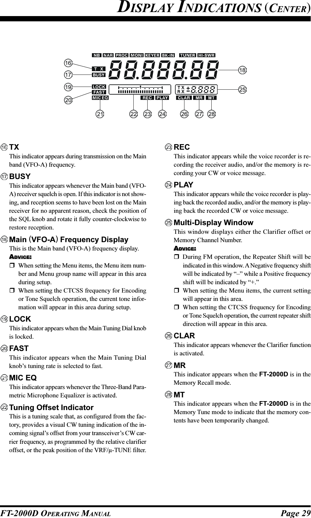
![Page 30 FT-2000D OPERATING MANUALSub (VFO-B) Receiver S-MeterDisplays the strength of signals received on the Subband (VFO-B).TXThis indicator appears during transmission on the Subband (VFO-B) frequency.BUSYThis indicator appears whenever the Sub band (VFO-B) receiver squelch is open. If this indicator is not show-ing, and reception seems to have been lost on the Subreceiver for no apparent reason, check the position ofthe Sub [SQL] knob and rotate it fully counter-clock-wise to restore reception.Sub (VFO-B) Frequency DisplayThis is the Sub band (VFO-B) frequency display.ADVICE:When setting the Menu items, the Menu item namewill appear in this area during setup.When setting the CTCSS frequency for Encodingor Tone Squelch operation, the current tone fre-quency will appear in this area during setup.When activating the CW Spot Tone, the current tonefrequency will appear in this area.LSB, USB, CW, AM, FM, RTTY, PKTDisplays the currently-selected operating mode for theSub (VFO-B) receiver.FASTThis indicator appears when the [SUB VFO-B] knob’stuning rate is selected to fast.AGC A, F, M, SDisplays the currently-selected AGC decay time forthe Sub (VFO-B) receiver.A: Auto, F: Fast, M: Medium, S: SlowNBThis indicator appears when the Sub (VFO-B)receiver’s (short duration) Noise Blanker is activated.This indicator will blink for three seconds, and there-after appears continuously, when the Sub (VFO-B)receiver’s longer-pulse Noise Blanker is activated.NARThis indicator appears whenever the optional Sub(VFO-B) receiver’s narrow filter is selected.DISPLAY INDICATIONS (RIGHT SIDE)](https://usermanual.wiki/Yaesu-Musen/20251X70.Users-Manual-1/User-Guide-738937-Page-32.png)
![Page 31FT-2000D OPERATING MANUALREAR PANELRX ANT OUT JackThis BNC jack provides output of the receiver signallines from the Antenna jacks which are connected to“RX” side of the transceiver’s main T/R switching cir-cuitry.RX ANT IN JackThis type-M jack is for a separate receive-only antenna.An antenna connected here can be used when the [RX]antenna button on the front panel is pressed.If you want to use some special kind of externalbandpass filter or preamplifier, you may connect itbetween the RX ANT OUT and RX ANT IN jacks.ANT 1/2 JacksConnect your main antenna(s) here, using a type-M(PL-259) plug and coaxial feedline for each. These an-tenna ports are always used for transmission, and alsoare used for reception unless a separate receive an-tenna is also used for the receiver. The internal antennatuner affects only the antenna(s) connected here, andonly during transmission.COOLING FANThis is a cooling fan for cooling down the internalpower supply unit.Usually, this cooling fan does not rotation. However,when the temperature begins to rise, a cooling fan be-gins a rotation.DC 13.8 V ...– IN JackConnect this 6-pin connector to the DC 13.8 V OutputJack on the FP-2000 AC Power Supply, using the sup-plied DC Power Cord. This connector provides +13.8V DC supply voltage for the FT-2000D.DC 50 V ...– IN JackConnect this 2-pin connector to the DC 50 V OutputJack on the FP-2000 AC Power Supply, using the sup-plied DC Power Cord. This connector provides +50 VDC supply voltage for the power amplifier of the FT-2000D.GNDUse this terminal to connect the transceiver to a goodearth ground, for safety and optimum performance. Usea large diameter, short braided cable for making groundconnections, and please refer to page 9 for other notesabout proper grounding.µ-TUNE JacksThese jacks are used for signal input/output of the op-tional RF µTuning Kit.ANTENNA (1/2) SWITCHANT “1”ANT “2”RX ANT “IN”RX ANT “OUT”ANTENNA (RX) SWITCHTX/RX RELAYTransmitter SectionRece iver Se ction](https://usermanual.wiki/Yaesu-Musen/20251X70.Users-Manual-1/User-Guide-738937-Page-33.png)
![Page 32 FT-2000D OPERATING MANUALROT (ROTATOR) JackThis 5-pin MINI-DIN Jack accepts a cable connectedto a YAESU G-800DXA/-1000DXA/-2800DXA An-tenna Rotator (listed models are current as of early2006). You may control the antenna azimuth rotation(and rotation speed) using the Function buttons on thefront panel.BND (BAND) DATA JackThis 8-pin output jack provides band selection datawhich may be used for control of optional accessoriessuch as the VL-1000 Solid-state Linear Amplifier.PACKET JackThis 5-pin input/output jack provides receiver audioand squelch signals, and accepts transmit (AFSK) au-dio and PTT control, from an external Packet TNC.Pinout is shown on page 15. The receiver audio levelat this jack is approximately 100 mVp-p (@600 Ohms).RTTY JackThis 4-pin input/output jack provides connections foran RTTY terminal unit. Pinout is shown on page 15.The receiver audio level at this jack is at a constant100-mV (@600 Ohms) level. FSK keying at this jackis accomplished by a closure of the SHIFT line toground by the terminal unit.PTT JackThis RCA input jack may be used to provide manualtransmitter activation using a footswitch or otherswitching device. Its function is identical to the [MOX]button on the front panel. The same line is available atthe PACKET and RTTY jacks for TNC control. Open-circuit voltage is +13.5 VDC, and closed-circuit cur-rent is 5 mA.MIC (PATCH) JackThis RCA input jack accepts transmitter audio - eitherAFSK or voice - for transmission. This line is mixedwith the microphone audio input line, so the micro-phone should be disconnected if using this jack andmixing is not desired. The optimum impedance is 500~ 600 Ohms, and the nominal input level should be 5mV.TRV JackThis RCA jack provides a low level RF output for usewith a transverter. Maximum output is approximately–10 dBm (0.1 mW) at 50 Ohms.REC JackThis RCA jack provides low-level receiver audio out-put and transmit audio, for recording or external am-plification. Peak signal level is 30 mVp-p at 10 kOhms.EXT ALC JackThis RCA input jack accepts negative-going externalALC (Automatic Level Control) voltage from a linearamplifier, to prevent over-excitation by the transceiver.Acceptable input voltage range is 0 to –4 VDC.REAR PANEL](https://usermanual.wiki/Yaesu-Musen/20251X70.Users-Manual-1/User-Guide-738937-Page-34.png)
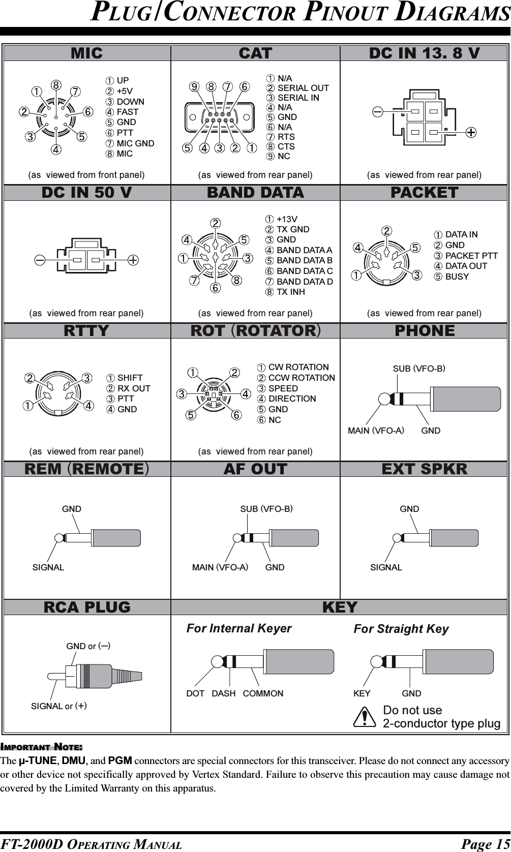
![Page 33FT-2000D OPERATING MANUALTX REQ JackWhen this RCA jack shorted to ground, it puts the FT-2000D into the transmit mode, and sends out a steadyCW carrier, for linear amplifier or manual antenna tuneradjustment.TX GND JackThis RCA jack’s center pin is closed to ground whilethe transceiver’s transmitter is engaged. It may be usedfor control of a peripheral device, most typically a lin-ear amplifier. To enable this jack, please set Menu item“144 tGEn ETX-GND” to the “EnA” (Enable) selec-tion.The relay circuit of the FT-2000D used for this jack iscapable of switching AC voltage of 100 Volts at up to300 mA, or DC voltages or 60 V at 200 mA or 30 V atup to 1 Amp.+13.8 V JackThis RCA output jack provides regulated, separatelyfused 13.8 VDC at up to 200 mA, to power an externaldevice such as a packet TNC. Make sure your devicedoes not require more current (if it does, use a separatepower source).AF OUTThis gold-plated 3-contact jack provides dual-channellow-level receiver output, for recording or external am-plification. Peak signal level is 300 mVp-p at 10 k-Ohms. Main band (VFO-A) receiver audio is on theleft channel (tip), and sub band (VFO-B) receiver au-dio is on the right channel (ring). A stereo amplifier orrecorder is recommended, to record each receiver’saudio separately when dual reception is enabled (au-dio from either receiver, or both, may be used via thisjack). The front panel [AF GAIN] knobs do not affectthe signals at this jack.REM (REMOTE) JackBy plugging in the optional FH-2 Remote Control Key-pad to this gold-plated jack, direct access to the FT-2000D CPU is provided for control functions such ascontest memory keying, plus frequency and functioncontrol.EXT SPKRThis gold-plated two-contact output jack provides re-ceiving audio from the Main (VFO-A) and Sub (VFO-B) receivers for an external loudspeaker or speakers,such as the SP-2000. Inserting a plug into this jackdisables the internal loudspeaker. Impedance is 4 ~ 8Ohms.µ-TUNE JackThis 10-pin MINI-DIN jack used for control of theoptional RF µTuning Kit.DMU JackThis 8-pin MINI-DIN jack accepts a cable connectedto an optional DMU-2000 Data Management Unit.PGM (PROGRAM) JackThis coverd 9-pin MINI-DIN jack is used at the fac-tory. Please do not connect any equipment to this jack.CAT JackThis 9-pin serial DB-9 jack allows external computercontrol of the FT-2000D. Connect a serial cable hereand to the RS-232C COM port on your personal com-puter (no external interface is required).KEY JackThis 1/4-inch phone jack accepts a CW key or keyerpaddle. A 2-contact plug cannot be used in this jack.Key-up voltage is +5 V, and key-down current is 1 mA.Plug wiring is shown on page 15, and this jack may beconfigured for keyer, “Bug,” “straight key,” or com-puter keying interface operation via Menu item “054A1A R-TYPE.”REAR PANEL](https://usermanual.wiki/Yaesu-Musen/20251X70.Users-Manual-1/User-Guide-738937-Page-35.png)
![Page 34 FT-2000D OPERATING MANUALFP-2000 SWITCHES & JACKSPOWER SwitchThis is the FP-2000’s main ON (I)/OFF (O) switch.When turn on the FP-2000, the LED indicator willglow red several seconds later.If this main switch is not set to the “(I)” position, theFT-2000D’s [POWER] switch will not function.AC IN JackConnect the supplied 3-wire AC line cord to this socket.Cooling FanThis is a cooling fan for cooling down the internalpower supply unit.Usually, this cooling fan does not rotation. However,when the temperature begins to rise, a cooling fan be-gins a rotation.OUTPUT DC 13.8 V JackConnect this 6-pin connector to the DC 13.8 V InputJack on the FT-2000D, using the supplied DC PowerCord. The DC output is 13.8 Volts, with maximumcurrent of 6 Amps.OUTPUT DC 50 V JackConnect this 2-pin connector to the DC 50 V InputJack on the FT-2000D, using the supplied DC PowerCord. The DC output is 50 Volts, with maximum cur-rent of 12 Amps.FUSEThis holder requires a 15-A fuse. Always use the 10Amp fuse, whether operating on 100 - 120 VAC or200 - 240 VAC.NOTERarely, when a rush current flowed, the FP-2000is buzzed faintly. This is normal condition.](https://usermanual.wiki/Yaesu-Musen/20251X70.Users-Manual-1/User-Guide-738937-Page-36.png)
![Page 35FT-2000D OPERATING MANUALBefore turning on main power, please verify the following items once more.Have you made all ground connections securely? See page 9 for details.Do you have your antenna(s) connected to the rear-panel Antenna jack(s)? See page 10 for details.Is your microphone (and/or key or paddle) connected? See pages 11 and 12 for details.If using a linear amplifier, have all interconnections been successfully completed? See pages 13 and 14 for details.Please rotate both [AF GAIN] controls to their fully counter-clockwise positions, to avoid a loud blast of audio whenthe transceiver turns on. See page 21 for details.Rotate the [RF PWR] control fully counter-clockwise, to set minimum power at first. See page 21 for details.If your AC mains power should suffer a significant fluctuation or interruption, we recommend that you go through acomplete power-up cycle, in order to ensure that all circuits are properly initialized. To do this, be sure the FT-2000D’s[POWER] switch is turned off, then set the FP-2000’s [POWER] switch to the “O” position. Now unplug the ACcable from the rear panel of the FP-2000, and wait ten seconds before proceeding with the start-up procedure describedon next page.BASIC OPERATION:RECEIVING ON AMATEUR BANDS](https://usermanual.wiki/Yaesu-Musen/20251X70.Users-Manual-1/User-Guide-738937-Page-37.png)
![Page 36 FT-2000D OPERATING MANUAL+CLARMain Tuning Dial knob[ANTENNA] Button[MODE] Button[SQL] KnobSub [SQL] Knob [A/B] Button(VFO-A) [BAND] Button(VFO-A) [MHz] Button[FAST] Button(VFO-B) [BAND] Button(VFO-B) [MHz] Button[SUB VFO-B] Knob1. Set the FP-2000’s [POWER]switch to “I” position.2. Press and hold in the FT-2000D’s[POWER] switch for one secondto turn the transceiver on.3. The transceiver will start up on 7.000.00MHz LSB, and normal operation may begin.NOTE:To turn power off, press and hold in the FT-2000D’s[POWER] switch for one second.4. Rotate the [AF GAIN] knob to seta comfortable audio level on incom-ing signals or noise. Clockwise ro-tation of the [AF GAIN] knob in-creases the volume level.NOTE:When using headphones, start by rotating the [AFGAIN] knob counter-clockwise, then bring the volumelevel up after you put the headphones on. This willminimize the chance of damage to your hearing causedby an unexpectedly-high audio level.5. Press the Main [RX] but-ton to engage the Main(VFO-A) receiver; theimbedded LED will glowGreen.ADVICE:If you press the Main[RX] button when the imbedded LED is alreadyglowing Green, the LED will now blink on and off;this indicates that the Main (VFO-A) receiver istemporarily muted. Just press the Main [RX] but-ton once more to restore Main (VFO-A) receiveroperation.Press the Sub [RX] button toengage Dual Reception (us-ing the Sub (VFO-B) re-ceiver in addition to theMain (VFO-A) receiver).When you press the Sub[RX] button, its imbedded LEDwill glow green; pressing thisbutton once more will turn offthe Sub (VFO-B) receiver, andthe imbeded LED will go dark.Use the Sub receiver’s Sub [AFGAIN] knob to adjust the Sub(VFO-B) receiver volume level.6. Press the [BAND] but-ton corresponding tothe Amateur band onwhich you wish to be-gin operation.ADVICE:One-touch selec-tion of each Ama-teur band between1.8 and 50 MHz is provided.The FT-2000D utilizes a triple band-stack VFOselection technique, which permits you to store upto three favorite frequencies and modes onto eachband’s VFO register. For example, you may storeone frequency each on 14 MHz CW, RTTY, andUSB, then recall these VFOs by successive, mo-mentary presses of the [14] MHz band button. EachAmateur band button may similarly have up to threefrequency/mode settings applied.[POWER] SwitchMain [RX] Button[AF GAIN] KnobSub [AF GAIN] Knob[BAND] ButtonSub [RX] ButtonBASIC OPERATION:RECEIVING ON AMATEUR BANDSHere is the typical start-up procedure for normal operation:](https://usermanual.wiki/Yaesu-Musen/20251X70.Users-Manual-1/User-Guide-738937-Page-38.png)
![Page 37FT-2000D OPERATING MANUALIf you press the (VFO-A) [BAND] button, the[SUB VFO-B] knob may be used as a band selec-tion knob. If you press the (VFO-A) [MHz] but-ton, rotation of the [SUB VFO-B] knob allows fre-quency navigation in 1 MHz steps. Depending onthe setting of the (VFO-A) [BAND], (VFO-A)[MHz], and [A/B] buttons, the function of the [SUBVFO-B] knob will change.When operating on the FMmode, rotate the [SQL](Squelch) knob clockwise justto the point where the back-ground noise is just silenced.This is the point of maximumsensitivity to weak signals. Excessiveadvancement of the [SQL] knob willdegrade the ability of the receiver todetect weak signals. Adjustment of theSub band (VFO-B) Squelch is accom-plished using the Sub [SQL] knob.9.Rotate the Main Tuning Dial knob to tune around theband, and begin normal operation.ADVICE:Clockwise rotation of the Main Tuning Dial knobincreases the operating frequency, one “step” of thesynthesizer at a time; similarly, counter-clockwiserotation of the Main Tuning Dial knob will decreasethe frequency.Two steps, one “normal”and one “fast,” are availableon each operating mode.Pressing the [FAST] buttonengages the “Fast” tuningselection.It is possible to separate the frequency change overone dial rotation, only while operating solely onthe CW mode, using the Menu items “116 tunDIALSTP,” and “117 tun CW FINE.” See page 127.If you want to navigate quickly, so as to effect rapidfrequency change, there are several techniquesavailable:Direct keyboard entry of the frequency (see page49).Use the [SUB VFO-B] knob to tune in 1 MHzsteps (see page 49).Use the microphone’s [UP]/[DWN] scanningkeys, if your microphone is so equipped (seepage 49).7. Press the [ANTENNA 1/2] button to select the appro-priate antenna for the band in use; alternatively, if oneis connected, you may also press the[ANTENNA RX] antenna selectionbutton. Two TX/RX antennas may beconnected, or one RX-only antenna.ADVICE:Once you have made your antenna selection, that an-tenna is “remembered” by the microprocessor in con-junction with the VFO register (frequency and mode)in use when you chose that particular antenna.8. Press the appropriate [MODE] but-ton to select the desired operatingmode.ADVICE:By convention in the Amateurbands, LSB is used on the 7 MHzand lower bands (with the excep-tion of 60 meters), while USB isutilized on the 14 MHz andhigher bands.When changing modes from SSBto CW, you will observe a fre-quency shift on the display. This shift representsthe BFO offset between the “zero beat” frequencyand the audible CW pitch (tone) you can hear (thepitch is programmed by the [PITCH] knob), eventhough the actual tone that you hear is not chang-ing. If you do not want this frequency shift to ap-pear when changing modes from (for example) USBto CW, use the Menu item “061 A1A FRQDISP,”described on page 122.BASIC OPERATION:RECEIVING ON AMATEUR BANDSMAIN TUNING DIAL KNOB TUNING RATEOPERATING MODE 1 STEP 1 DIAL ROTATIONLSB, USB, CW, 10Hz 10kHzRTTY, PKT(LSB)[100Hz][100kHz]AM, FM, PKT(FM)100Hz [1kHz]100kHz [1MHz][ ] : [FAST] switch set to “ON”](https://usermanual.wiki/Yaesu-Musen/20251X70.Users-Manual-1/User-Guide-738937-Page-39.png)
![Page 38 FT-2000D OPERATING MANUALOPERATION ON 60-METER (5 MHZ) BAND (U.S. VERSION ONLY)The FT-2000D includes the capability for transmission and reception on the five spot frequencies assigned to the Ama-teur Service in the United States. To operate on the 5 MHz band:1. Press the [V/M] button once to enter the “Memory”mode (a memory channel number “USx” will appearon the Multi-Display Window in the display.2. Press the [M CH] button. The LED imbedded in thebutton will glow red to signify that rotation of the [SUBVFO-B] knob will allow selection the memory chan-nel.ADVICE:If the memory channel selection seems not to be oper-ating, check see if the orange lamp to the right of the[SUB VFO-B] knob is illuminated. If so, pressing the[A/B] button will cause the orange lamp to the right ofthe [SUB VFO-B] knob to go out. Now, press the [MCH] button to begin memory channel selection.3. Memory channels “US1” through “US5” are pre-pro-grammed, at the factory, with the permitted frequen-cies in the 5 MHz band, and the USB mode is auto-matically selected on these channels.4. To exit from 60-meter operation and return to the VFOmode, just press the [V/M] button.NOTE:The frequencies and operating mode for 5 MHz band op-eration are both fixed, and may not be changed.Main Tuning Dial Knob[SUB VFO-B] Knob[V/M] Button[M CH] Button[A/B] ButtonBASIC OPERATION:RECEIVING ON AMATEUR BANDS](https://usermanual.wiki/Yaesu-Musen/20251X70.Users-Manual-1/User-Guide-738937-Page-40.png)
![Page 39FT-2000D OPERATING MANUALBASIC OPERATION:RECEIVING ON AMATEUR BANDSCLAR (CLARIFIER) OPERATION ON MAIN (VFO-A)The [TX CLAR], [RX CLAR], [CLEAR] buttons and [SUB VFO-B] knob are used to offset either the receive, transmit,or both frequencies from their settings on the Main band (VFO-A) frequency (the Clarifier does not affect the Sub band(VFO-B), however). The four small numbers on the Multi-Display Window show the current Clarifier offset. The Clarifiercontrols on the FT-2000D are designed to allow you to preset an offset (up to ±9.990 kHz) without actually retuning, andthen to activate it via the Clarifier’s [RX CLAR] and [TX CLAR] buttons. This feature is ideal for following a driftingstation, or for setting small frequency offsets sometimes utilized in DX “Split” work.Here is the technique for utilizing the Clarifier:1. Press the [RX CLAR] button. In the Multi-DisplayWindow, the “RX” notation willappear, and the programmed off-set will be applied to the receivefrequency.2. Rotation of the [CLAR] knob will allow you to modifyyour initial offset on the fly. Offsets of up to ±9.990kHz may be set using the Clarifier.To cancel Clarifier operation, press the [RX CLAR] but-ton. The “RX” notation will disappear from the display.ADVICE:Turning the Clarifier Off simply cancels the application ofthe programmed offset from the receive and/or transmitfrequencies. To clear out the programmed Clarifier offsetaltogether, and reset it to “zero,” press the [CLEAR] but-ton. The programmed offset is displayed in the small multi-channel window of the frequency display.[RX CLAR] Button[TX CLAR] Button[CLEAR] Button[CLAR] KnobTX CLARWithout changing the receive frequency, you mayalternatively apply the Clarifier offset to the trans-mit frequency (typically, for “split” DX pile-ups).See page 79 for details.The Tuning Offset Indicator provides a graphical representation of the Clarifier offset.On CW, the Tuning Offset Indicator is used for CW Center Tuning, instead of Clarifier Offset, as the transceiver isconfigured at the factory. If you wish to change this, so that the Clarifier Offset is also displayed on CW, use thefollowing procedure:+CLA RMain Tuning Dial knob [SUB VFO-B] knob[MENU] Button1. Press the [MENU] button to enter the Menu mode.2. Rotate the Main Tuning Dial knob to select Menuitem “010 diSP BAR SEL.”3. Rotate the [SUB VFO-B] knob to select “CLAr(Clarifier)” (replacing the default “C-tn (CW TUN-ING)” selection).4. Press and hold inthe [MENU] but-ton for two secondsto save the new set-ting and exit to nor-mal operation.(TX Frequency < RX Frequency)(TX Frequency = RX Frequency)(TX Frequency > RX Frequency)](https://usermanual.wiki/Yaesu-Musen/20251X70.Users-Manual-1/User-Guide-738937-Page-41.png)
![Page 40 FT-2000D OPERATING MANUALLOCKYou may lock the setting of the Main Tuning Dial knob, to prevent accidental frequency change.To lock out the Main Tuning Dialknob, just press the [LOCK] but-ton that is located to the right of theDial. To unlock the Dial setting, andrestore normal tuning, just press the[LOCK] button once more.DIMThe illumination level of the analog meter and frequency display may be reduced, if you are using the transceiver in a darkenvironment where high brightness is not desired.To reduce the illumina-tion level, press the[DIM] button, locatedto the left of the analogmeter. To restore fullbrightness, press the[DIM] button oncemore.You may also customize the amount of brightness reduc-tion engaged by the pressing of the [DIM] button, and mayuse different brightness levels for different front panel ar-eas. Menu item “008 diSP DIM MTR” adjusts the bright-ness level of the analog meter; while menu item “009 diSPDIM VFD” sets the brightness levels of the frequency dis-play (these settings are effective only when the [DIM] but-ton is pressed).BASIC OPERATION:RECEIVING ON AMATEUR BANDS[DIM] Button[LOCK] Button](https://usermanual.wiki/Yaesu-Musen/20251X70.Users-Manual-1/User-Guide-738937-Page-42.png)

![Page 42 FT-2000D OPERATING MANUALADVICE:When operating in Dual Receive, the manner in whichthe audio is fed to the left and right sides of your head-phones (Stereo, Monaural, or Mixed) may be config-ured using Menu item “089 rout HEADPHN” (seepage 124).When changing modes from SSB to CW, you will ob-serve a frequency shift on the display. This shift repre-sents the BFO offset between the “zero beat” frequencyand the audible CW pitch (tone) you can hear (the pitchis programmed by the [PITCH] knob), even thoughthe actual tone that you hear is not changing. If you donot want this frequency shift to appear when changingmodes from (for example) USB to CW, use the Menuitem “061 A1A FRQDISP,” described on page 122.When operating on the FM mode on the Sub band(VFO-B), rotate the Sub [SQL] knob clockwise justto the point where the background noise is just silenced.This is the point of maximum sensitivity to weak sig-nals. Excessive advancement of the Sub [SQL] knobwill degrade the ability of the receiver to detect weaksignals. Adjustment of the Main band (VFO-A) Squelchis accomplished using the Main [SQL] knob.The frequency ranges of the various fixed bandpassfilters are shown in the chart below. You may operateon Dual Receivewith both receiversset within the samerange, even if theyare not on the sameAmateur band (forexample, the 14 and18 MHz, or 21 and24.9 MHz bands).Of course, a suitablemultiband antenna isrequired.DUAL RECEIVEThe FT-2000D is capable of simultaneous reception on the same amateur band, using the Main (VFO-A) and Sub (VFO-B) receivers, in what is called the Dual Receive mode. Especially useful for DX work, here is the operating procedure forDual Receive operation.CONVENIENCE FEATURES1. While receiving on the Main band (VFO-A), engagethe Sub (VFO-B) receiver by pressing the Sub [RX]button, located to the upper left of the [SUB VFO-B]knob. You will now be receiving on the two frequen-cies shown on the frequency display.2. Adjusting the volume:To adjust the Main (VFO-A) audio level, rotate theMain [AF GAIN] knob. To adjust the Sub (VFO-B)audio level, rotate the Sub [AF GAIN] knob. In bothcases, clockwise rotation of the knob will increase thevolume level.3. Press the [B] button. Within five seconds of pressingthe [B] button, while the orange LED is blinking, youmay now change the operating mode for the Sub (VFO-B) band by pressing the appropriate Mode selectionbutton.4. Having pressed the [B] button in the previous step,you may also press the [BAND] buttons to select theoperating band on which you want to set up the Sub(VFO-B) receiver.5. Rotate the Main Tuning Dial knob to adjust the Main(VFO-A) frequency, and rotate the [SUB VFO-B]knob to adjust the Sub (VFO-B) frequency.6. To cancel Dual Receive operation, and receive just onthe Main (VFO-A) receiver, press the Sub [RX] but-ton; the imbedded green LED will go out, andmonoband operation on the Main (VFO-A) receiverwill resume.NOTE:Please remember that, while the [B] mode button is blink-ing (for five seconds), any mode or band changes will stillbe applied to the Sub band (VFO-B), whether or not DualReceive is engaged.QUICK POINT:By convention in the Amateur bands, LSB is used on the 7MHz and lower bands (with the exception of 60 meters),while USB is utilized on the 14 MHz and higher bands.Main Tuning Dial Knob[SUB VFO-B] Knob[BAND] ButtonSub [RX] Button[SQL] Knob[B] Button[AF GAIN] KnobSub [AF GAIN] KnobSub [SQL] KnobRF BPF FREQUENCY DIVISION0.03000 MHz ~ 0.49999 MHz0.50000 MHz ~ 1.69999 MHz1.70000 MHz ~ 2.49999 MHz2.50000 MHz ~ 3.39999 MHz3.40000 MHz ~ 4.69999 MHz4.70000 MHz ~ 6.89999 MHz6.90000 MHz ~ 9.89999 MHz9.90000 MHz ~ 13.89999 MHz13.90000 MHz ~ 20.89999 MHz20.90000 MHz ~ 30.09999 MHz30.10000 MHz ~ 44.99999 MHz45.99999 MHz ~ 59.99999 MHz](https://usermanual.wiki/Yaesu-Musen/20251X70.Users-Manual-1/User-Guide-738937-Page-44.png)
![Page 43FT-2000D OPERATING MANUALCONVENIENCE FEATURESDUAL RECEIVEUsing Headphones for Dual ReceiveTo take advantage of dual reception, you will want to con-nect stereo headphones to the PHONES jack. Like theAF GAIN control, headphone audio mixing can also beconfigured as desired from Menu item “089 routHEADPHN.” Three audio mixing schemes are selectableas follows:SEP: Audio from the Main band (VFO-A) receiver isheard only in the left ear, and Sub band (VFO-B)receiver audio solely in the right ear.Con1: Audio from both Main band (VFO-A) and Subband (VFO-B) receivers can be heard in both ears,but Sub band (VFO-B) audio is attenuated in theleft ear and Main band (VFO-A) audio is attenu-ated in the right ear.Con2: Audio from both Main band (VFO-A) and Subband (VFO-B) receivers are combined and heardequally in both ears “Monaural” mode).Sideband Diversity ReceptionHere you receive a single AM signal through the two re-ceivers, each receiving the opposite sideband. Skywave-propagated signals often show phase distortion in thismode, but it gives you a view of the entire passband, fromwhich you can then select the best sideband for listening(or for SWL Dx’ing, you may want to listen to both side-bands at the same time, to get the best copy). Ongroundwave signals, where the phase of the sidebands islikely to be the same, there is an interesting sense of depthto the signal.To tune in a signal using this mode, you should have ste-reo headphones connected to the front panel PHONESjack.Set the Main band (VFO-A) to either LSB or USBmode, and tune for zero beat on the desired signal.Press the [AB] button to copy this mode and fre-quency into the Sub band (VFO-B), then press the modebutton to select the opposite sideband for the Main band(VFO-A).If using headphones, set the headphone mixing schemeto the “Con1” mode via the Menu item “089 routHEADPHN,” and activate dual reception.Adjust the [AF GAIN] knob(s) to balance the volumeof the two receivers.If interference is present on one of the channels, youmay have to turn its [AF GAIN] knob to suppress thatchannel (or press the green [RX] LED/button to dis-able the receiver with the sideband experiencing inter-ference). Otherwise, try changing the headphone au-dio mixing scheme to “Con2” or “SEP” in the Menuitem “089 rout HEADPHN,” for different effects (ortry settings with similar effects on your external am-plifier). Although you don’t get the “stereophonic” ef-fect in the monaural mode, the two signals are stillmixed, offering the potential for much better copy thanin regular AM or even single-sideband ECSS modes.](https://usermanual.wiki/Yaesu-Musen/20251X70.Users-Manual-1/User-Guide-738937-Page-45.png)
![Page 44 FT-2000D OPERATING MANUALBandwidth Diversity ReceptionThis mode involves receiving the same signal through twodifferent bandpass filters. The frequency and mode of boththe Main band (VFO-A) and Sub band (VFO-B) are thesame. The Main band (VFO-A) can be set up for a widebandpass, using the [WIDTH] knobs, and the Sub band(VFO-B) for a narrow bandpass, resulting in a spatial per-ception of the channel. Although any mode (except FM)can be used, CW offers the widest array of choices, andperhaps the most startling effects on crowded channels.Stereo headphones or an external stereo speaker are rec-ommended for this mode. To set up the transceiver forbandwidth diversity reception:Select the desired mode on the Main band (VFO-A).Tune to the signal of interest.Press the [AB] button to copy this mode and fre-quency into the Sub band (VFO-B).If using headphones, set the headphone mixing schemeto the “Con1” mode via the Menu item “089 routHEADPHN,” and activate dual reception.Adjust the [AF GAIN] knob(s) to balance the volumeof the two receivers.Now try manipulating the [SHIFT] and [WIDTH]knobs to observe the interesting effects of bandwidthdiversity.CONVENIENCE FEATURESDUAL RECEIVE](https://usermanual.wiki/Yaesu-Musen/20251X70.Users-Manual-1/User-Guide-738937-Page-46.png)
![Page 45FT-2000D OPERATING MANUALCONVENIENCE FEATURESP.BACK (AUDIO PLAYBACK) FROM MAIN (VFO-A) RECEIVEROnce engaged by the operator, the FT-2000D begins the automatic recording of the last 15 seconds of incoming receiveraudio on the Main band (VFO-A). This capability is especially useful for confirming a callsign that may have been difficultto copy due to noise or QRM, etc.RecordingPress and hold in the [F7(P.BACK)] button for two sec-onds to initiate record-ing; the “ ” iconwill appear in the displayto confirm that recordingis in progress. The re-corder will store up to 15seconds of the Mainband (VFO-A) receivedaudio, and will retain the most-recent 15 seconds of audioon a running basis.Pressing the [F7(P.BACK)] button once more will haltthe recording, and the “ ” icon will go out.NOTE:When the transceiver isturned off, the contents ofthe recording memory willbe erased!P.BACK feature from the optional FH-2 Remote Control KeypadThe [P/B] key of the optional FH-2 Remote Control Keypad can also serve as a remote-control recording/playbackswitch. Operation is described below.RecordingPress and hold in the FH-2’s [P/B] key for two sec-onds to initiate recording.The “ ” icon will appearin the display to confirm that re-cording is in progress.Press the FH-2’s [P/B] key mo-mentarily to halt recording; the“” icon will go out.You may also press the frontpanel’s [F7(P.BACK)] button(momentarily) to halt recording,as well.When the transceiver is turnedoff, the contents of the record-ing memory will be erased.[F7(P.BACK)] ButtonLOC KOFFONPlaybackPress the FH-2’s [P/B] key momentarily, after record-ing has been halted, to begin playback of the recordedaudio; the “ ” icon will appear in the display toconfirm that playback is in progress.. The last 15 sec-onds of audio will be heard in the speaker or head-phones. If you do not intervene, the entire 15 secondswill be played back, after which the playback will stopautomatically. To halt playback at any time, just pressthe [P/B] key momentarily again. The next time youpress the [P/B] key, it will pick up the playback whereyou left off. You may also press the front panel’s[F7(P.BACK)] button (momentarily) to play back therecorded audio, as well.ADVICEYou may adjust the playback level of the recording bythe main [AF GAIN] knobPlaybackPress the [F7(P.BACK)] button momentarily, after record-ing has been halted, to begin playback of the recordedaudio; the “ ” icon will appear in the display to con-firm that playback is in progress. The last 15 seconds ofaudio will be heard in the speaker or headphones. If youdo not intervene, the entire 15 seconds will be played back,after which the playback will stop automatically. To haltplayback at any time, just press the [F7(P.BACK)] buttonmomentarily again. The next time you press the[F7(P.BACK)] button, it will pick up the playback whereyou left off.ADVICEYou may adjust the playback level of the recording by themain [AF GAIN] knobStartStop15 Seconds[AF GAIN] Knob](https://usermanual.wiki/Yaesu-Musen/20251X70.Users-Manual-1/User-Guide-738937-Page-47.png)
![Page 46 FT-2000D OPERATING MANUAL“MY BANDS” OPERATIONWhen operating on an Amateur Band, it is possible to use the [BAND] buttons to engage the use of the [SUB VFO-B] knobfor Amateur band selection. The “My Bands” feature allows you to select several Amateur bands, and make only thosebands available for selection via the [SUB VFO-B] knob.This feature can be very useful in a contest, where the 10/18/24 MHz band are not used, or if you do not have antennas forsome bands.“My Bands” Setup1. Press the [MENU] button to engage the Menu mode.2. Rotate the Main Tuning Dial knob to select Menu item“122 tun MY BAND.”3. Rotate the [SUB VFO-B] knob to choose a band thatyou wish to skip (omit) from the band-selection loop(when using the [SUB VFO-B] knob for band selec-tion). The available choices are 1.8/3.5/5/7/10/14/18/21/24/28/50/GE (General Band)/AU (Transverter).4. Press the [ENT] button to set the omission commandto ON. The “E” (Enable) notation at the right of theband notation will change to “d” (disable).5. Repeat steps 3 and 4 to select/deselect as many bandsas you like.NOTE:The “ON” command sets the selected band to beskipped, while the “OFF” command sets the selectedband to be included in the band-selection list. Returnthe “d” notation to “E” to restore operation on a previ-ously-deleted band.6. Press and hold in the [MENU] button for two secondsto lock in the new configuration and exit to normaloperation.CONVENIENCE FEATURESMain Tuning Dial knob[SUB VFO-B] Knob[MENU] Button[ENT] Button[SUB VFO-B] Knob(VFO-A)[BAND] Button[A/B] Button(VFO-B)[BAND] Button14 MHz14 MHz18 MHz50 MHz21 MHz21 MHz7 MHz7 MHz5 MHz1.8 MHz28 MHz28 MHz24 MHz3.5 MHz3.5 MHz10 MHz14 MHz21 MHz7 MHz28 MHz3.5 MHzADVICE:The “My Band” feature affects both the Main (VFO-A)and Sub (VFO-B) bands.“My Band” Operation1. Press the (VFO-A) [BAND] button; the imbedded LEDwill glow Red, if you operate the “My Band” featureon the Main band (VFO-A).ADVICE:If the “My Band” feature on the Main band (VFO-A)seems not to be operating, check see if the orange lampto the right of the [SUB VFO-B] knob is illuminated.If so, pressing the [A/B] key will cause the orange lampto the right of the [SUB VFO-B] knob to go out. Now,press the (VFO-A) [BAND] button to begin “My Band”feature.2. Press the (VFO-B) [BAND] button; the imbedded LEDwill glow Orange, if you operate the “My Band” fea-ture on the Sub band (VFO-B).3. Rotate the [SUB VFO-B] knob to choose the Ama-teur band on which you wish to operate. Only thoseAmateur bands that have not been skipped will appearas you scroll through the bands.](https://usermanual.wiki/Yaesu-Musen/20251X70.Users-Manual-1/User-Guide-738937-Page-48.png)
![Page 47FT-2000D OPERATING MANUALCONVENIENCE FEATURESBAND STACK OPERATIONThe FT-2000D utilizes a triple band-stack VFO selection technique, that permits you to store up to three favorite frequen-cies and modes onto each band’s VFO register. For example, you may store one frequency each on 14 MHz CW, RTTY, andUSB, then recall these VFOs by successive, momentary presses of the [14] MHz band button. Each Amateur band key maysimilarly have up to three frequency/mode settings applied. Both the Main (VFO-A) and Sub (VFO-B) systems have theirown, independent, band stacks.A typical setup, for the 14 MHz band, might be arranged like this:1. Program 14.025 MHz, CW Mode, then press the [14]MHz band button;2. Program 14.080 MHz, RTTY Mode, then press the [14]MHz band button;3. Program 14.195 MHz, SSB Mode, then press the [14]MHz band button.With this configuration, successive momentary presses ofthe [14] MHz band button will allow you to toggle se-quentially through these three VFOs.C.S (CUSTOM SWITCH)An often-used Menu mode selection may be brought out to the front panel’s [C.S] button.[BAND] SwitchUSBRTTYCWC.S Setup1. Press the [MENU] button to engage the Menu mode;the Menu list will appear on the display.2. Rotate the Main Tuning Dial knob to select the Menuitem you want to be able to access via the [C.S] but-ton.3. Press and hold in the [C.S] button for two seconds tolock in your selection.4. Press and hold in the [MENU] button for two secondsto save the new configuration and exit to normal op-eration.Menu Selection Recall via [C.S] buttonPress the [C.S] button.The programmed Menu item will appear on the display.You may now rotate the [SUB VFO-B] knob to changethe setting of this menu item. Press the [MENU] buttonfor two seconds, when you are done, to save the new con-figuration and exit to normal operation.Main Tuning Dial Knob[C.S] Button[MENU] Button[SUB VFO-B] Knob[MENU] Button[C.S] Button](https://usermanual.wiki/Yaesu-Musen/20251X70.Users-Manual-1/User-Guide-738937-Page-49.png)
![Page 48 FT-2000D OPERATING MANUALROTATOR CONTROL FUNCTIONSWhen using a YAESU model G-800DXA, G-1000DXA, or G-2800DXA rotator (not supplied), it is possible to control itfrom the front panel of the FT-2000D.1 Press and hold in the [ENT] button (one of the [BAND]button) for two seconds. The frequency display areawill change over to the “Rotator Control” configura-tion.2 Press either the [F2(CH-2)] button or the [F3(CH-3)]button to rotate the antenna. Pressing the [F2(CH-2)]button will cause rotation to the left (counter-clock-wise), while pressing the [F3(CH-3)] button will causerotation to the right (clockwise).3 Press the [F5(MEM)] button or the [F6(DEC)] buttonto control the speed of rotation. Pressing the[F5(MEM)] button will cause slower rotation, whilepressing the [F6(DEC)] button will speed up rotation.Usually, you will be using the “100%” setting.When you are through exercising rotator control, press the[ENT] button momentarily. The frequency display willreturn to the main display field.[F2(CH-2)], [F3(CH-3)] Button[F5(MEM)], [F6(DEC)] Button [ENT] ButtonCONVENIENCE FEATURESCounter-clockwise RotationClockwise Rotation Speed DownSpeed UpSpeed (0 % ~ 100 %)Direction (0° ~ 360°)“Overlap” Indicator~AC INANT 1ANT 2EXT CONTROLREMOTECONTROLROTEXTCONTROLSELECTSWITCHPRESETADJOPERATIONMODEADJ. MODE FULLSCALEADJOVERLAPLED ADJOUT VOLADJABOPTIONAL CONNECTION CA BLE ()T9101556](https://usermanual.wiki/Yaesu-Musen/20251X70.Users-Manual-1/User-Guide-738937-Page-50.png)
![Page 49FT-2000D OPERATING MANUALMORE FREQUENCY NAVIGATION TECHNIQUESKeyboard Frequency EntryYou may enter operating frequencies, for either the Main(VFO-A) or Sub (VFO-B) bands, using the front panelband/frequency selection keys.Example 1:Enter 14.250.00 MHz into the Main band (VFO-A):1. Press the [ENT] buttonto engage the direct fre-quency entry process.Now, beginning withthe “10 MHz” digit ofthe frequency (theleftmost digit), we willenter the required dig-its of the frequency.2. Press, in order, the digits of the operating frequency,using the [BAND] buttons (which have the frequency-entry digit or decimal point on the right side of theslash bar). In this example, enter[1.8/1] [10/4] [GEN/.] [3.5/2] [14/5] [50/0] [50/0] [50/0] [50/0]The decimal point after the “MHz” portion of the fre-quency must be entered, but no decimal point is re-quired after the “kHz” portion.3. Press the [ENT] button once more. A short “beep” willconfirm that the frequency entry was successful, andthe new operating frequency will appear on the Main(VFO-A) frequency display fields.Example 2:Enter 7.100.000 MHz into the Sub band (VFO-B):1. Press the [B] button.2. Within five seconds (blinking theimbedded orange LED) of pressingthe [B] button, press the [ENT] but-ton to engage the direct frequency entry process. Now,beginning with the “10 MHz” digit of the frequency(the leftmost digit), we will enter the required digits ofthe frequency to be entered into the Sub band (VFO-B) register.3. Press, in order, the digits of the operating frequency,using the [BAND] buttons (which have the frequency-entry digit or decimal point on the right side of theslash bar). In this example, enter[21/7] [GEN/.] [1.8/1] [50/0] [50/0] [50/0] [50/0] [50/0]4. Press the [ENT] button once more. A short “beep” willconfirm that the frequency entry was successful, andthe new operating frequency will appear on the Sub(VFO-B) frequency display fields.ADVICE:If you attempt to enter a frequency outside the operat-ing range of 30 kHz ~ 60 MHz, the microprocessorwill ignore the attempt, and you will be returned toyour previous operating frequency. If this happens,please try again, taking care not to repeat the error inthe frequency entry process.Using the [SUB VFO-B] knobYou may change the Main band (VFO-A) frequency in 1MHz steps. If you press the (VFO-A) [BAND] button, the1 MHz steps will be applied to the Main band (VFO-A)frequency. The imbedded LED in the (VFO-A) [BAND]button will glow Red in the latter case.When tuning in 1 MHz steps, clockwise rotation of the[SUB VFO-B] knob will increase the frequency, whilecounter-clockwise rotation will decrease the frequency.Using the UP/DOWN Switches of the Supplied MH-31B8 Hand MicrophoneThe [UP]/[DWN] switches onthe supplied MH-31B8 HandMicrophone may also be usedfor manually scanning upward ordownward in frequency, respec-tively.The microphone’s [UP]/[DWN]switches utilize the tuning steps ofthe Main Tuning Dial knob; moreover,when the microphone’s [FAST] key ispressed, the tuning rate increases by afactor of ten, in a manner similar to theeffect of the transceiver’s front-panel[FAST] button.ADVICE:In the AM and FM modes, you may independently set thetuning steps when using the [UP]/[DWN] switches. To setnew tuning steps, use Menu items “119 tun AM STEP”and “120 tun FM STEP.”CONVENIENCE FEATURESDYNAMIC MICROPHONEMH-31DWN FST UP[DWN] Button[FST] Button[UP] Button](https://usermanual.wiki/Yaesu-Musen/20251X70.Users-Manual-1/User-Guide-738937-Page-51.png)

![Page 51FT-2000D OPERATING MANUALIPO (INTERCEPT POINT OPTIMIZATION)The IPO feature allows the operator to optimize the characteristics of the receiver front end, depending on the current noiselevel and the strength of incoming signals.Press the [IPO] button several times to set thedesired characteristic of the receiver front end,per the chart below.AMP1: Amplifies the incoming signal path using alow distortion RF preamplifier (gain: approx.10 dB).AMP2: Amplifies incoming signal path using a 2-stage low-distortion RF preamplifier (totalgain: approx. 17 dB).ON: Bypasses the RF preamplifier, yielding di-rect feed to the first mixer.The selected receiver RF preamplifier will be indicated inthe IPO columnof the ReceiverConfigurationIndicator on the display.ADVICE:On the 10 MHz and lower bands, it generally is not necessary to use any preamplifier at all; selecting the “ON” positiondescribed above will increase the strong-signal-handling capability of the receiver, and generally will result in more pleas-ant reception due to reduced noise. If you can hear band noise with the preamplifiers disengaged, then a preamplifier isgenerally not needed.ATTEven with the IPO function on, extremely strong local signals or high noise can still degrade reception. In such situations,you can use the [ATT] button to insert 6, 12, or 18-dB of RF attenuation in front of the RF amplifier.Receiver Configuration Indicator[IPO] Button1. Press the [ATT] button several times to setthe desired attenuation level, per the chartbelow.OFF: Attenuator is Off–6 dB: The incoming signal power is reduced by 6dB (Signal voltage reduced by 1/2)–12 dB: The incoming signal power is reduced by 12dB (Signal voltage reduced by 1/4)–18 dB: The incoming signal power is reduced by 18dB (Signal voltage reduced by 1/8)The selectedattenuationlevel will beindicated in the ATT column of the Receiver Configu-ration Indicator on the display.Receiver Configuration Indicator[ATT] ButtonCONVENIENCE FEATURESADVICE:The Attenuator affects both the Main (VFO-A) and Sub (VFO-B) bands.If background noise causes the S-meter to deflect on clear frequencies, press the [ATT] button until the S-meter drops toabout “S-1.” This setting optimizes the trade-offs between sensitivity, noise, and interference immunity. Also, once you havetuned in a station you want to work, you may want to reduce sensitivity further (or add more attenuation) by pressing the[ATT] button to a more setting. This reduces the strength of all signals (and noise) and can make reception more comfort-able, important especially during long QSOs. When looking for weak signals on a quiet band, you will want maximumsensitivity, so the IPO should be disabled and the [ATT] button should be set to “OFF.” This situation is typical during quiettimes on frequencies above 21 MHz, and when using a small or negative-gain receiving antenna on other bands.2. To restore full signal strength through the Attenuatorcircuit area, press the [ATT] button to restore the ATTdisplay to the “OFF” position.AMP1AMPAMPAMP2ON](https://usermanual.wiki/Yaesu-Musen/20251X70.Users-Manual-1/User-Guide-738937-Page-53.png)
![Page 52 FT-2000D OPERATING MANUALRF GAIN (SSB/CW/AM MODES)The RF Gain controls provide manual adjustment of the gain levels for the receiver RF and IF stages, to account for noiseand/or signal strength conditions at the moment.1. The Main [RF GAIN] knob should, initially, be ro-tated to the fully clockwise position. This is the pointof maximum sensitivity, and counter-clockwise rota-tion will gradually reduce the system gain.2. The Sub [RF GAIN] knob operates identically to theMain [RF GAIN] knob. The fully clockwise positionof the Sub [RF GAIN] knob should always be utilizedas a starting point for operation.ADVICE:As the [RF GAIN] knob is rotated counterclockwiseto reduce the gain, the S-meter reading will rise. Thisindicates that the AGC voltage being applied to thereceiver is increasing (which causes a reduction in re-ceiver gain).Rotating the [RF GAIN] knob control to the fullycounter-clockwise position will essentially disable thereceiver, as the gain will be greatly reduced. In thiscase, as well, the S-meter will appear to be “pegged”against the right edge of the analog S-meter scale.The Sub [RF GAIN] knob operates identically to theMain [RF GAIN] knob. The effects of counter-clock-wise rotation of the Sub (VFO-B) receiver’s RF Gaincontrol may be observed visually on the Sub band(VFO-B) S-meter.QUICK POINT:Reception frequently can be optimized by rotating the[RF GAIN] knob slightly counter-clockwise to thepoint where the incoming noise level is just about thesame as the “stationary” meter needle position as setby the adjustment of the [RF GAIN] knob. This set-ting ensures that excessive gain is not being utilized,without so much gain reduction that incoming signalscannot be heard.The RF Gain control, along with the IPO and Attenua-tor features, all affect the system receiver gain in dif-ferent ways. As a first step in dealing with high noiseor a crowded, high-level signal environment, the IPOgenerally should be the first feature engaged, if the fre-quency is low enough to allow the preamplifier to bebypassed. Thereafter, the RF Gain and Attenuator fea-tures may be employed to provide precise, delicateadjustment of the receiver gain so as to optimize per-formance fully.CONVENIENCE FEATURESMain [RF GAIN] KnobSub [RF GAIN] Knob](https://usermanual.wiki/Yaesu-Musen/20251X70.Users-Manual-1/User-Guide-738937-Page-54.png)