Yaesu Musen 20305X30 Amateur Radio with Scanning Receiver User Manual Front Panel Controls Switches
Yaesu Musen Co., Ltd. Amateur Radio with Scanning Receiver Front Panel Controls Switches
UserManual.wiki
>
Yaesu Musen
>
20305X30 User Manual
users manual
Navigation menu
Upload a User Manual
Namespaces
Wiki Guide
HTML
PDF
Info
Views
User Manual
Discussion / Help
Navigation
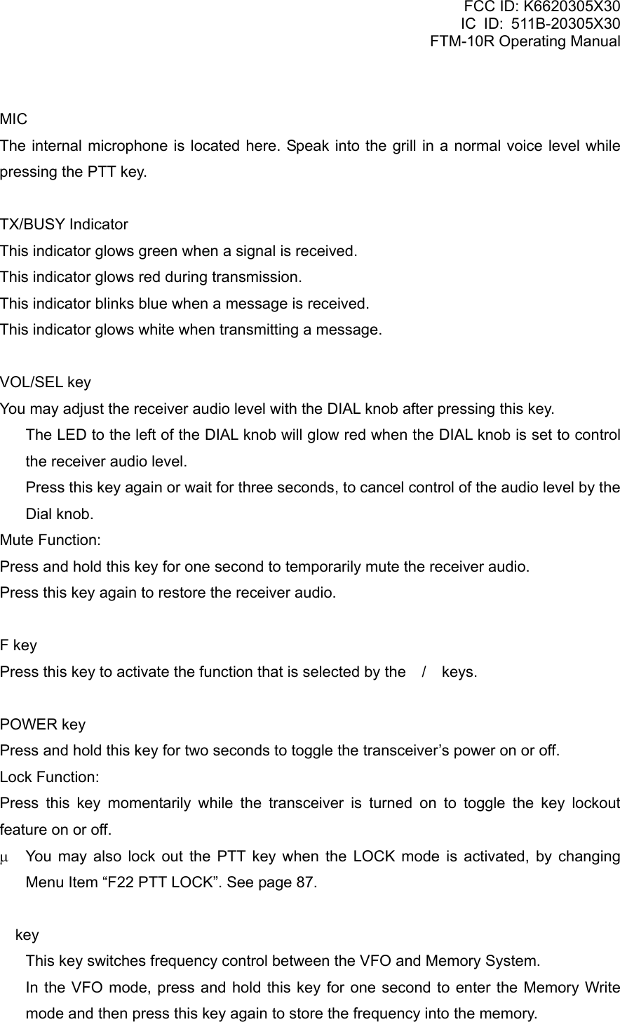
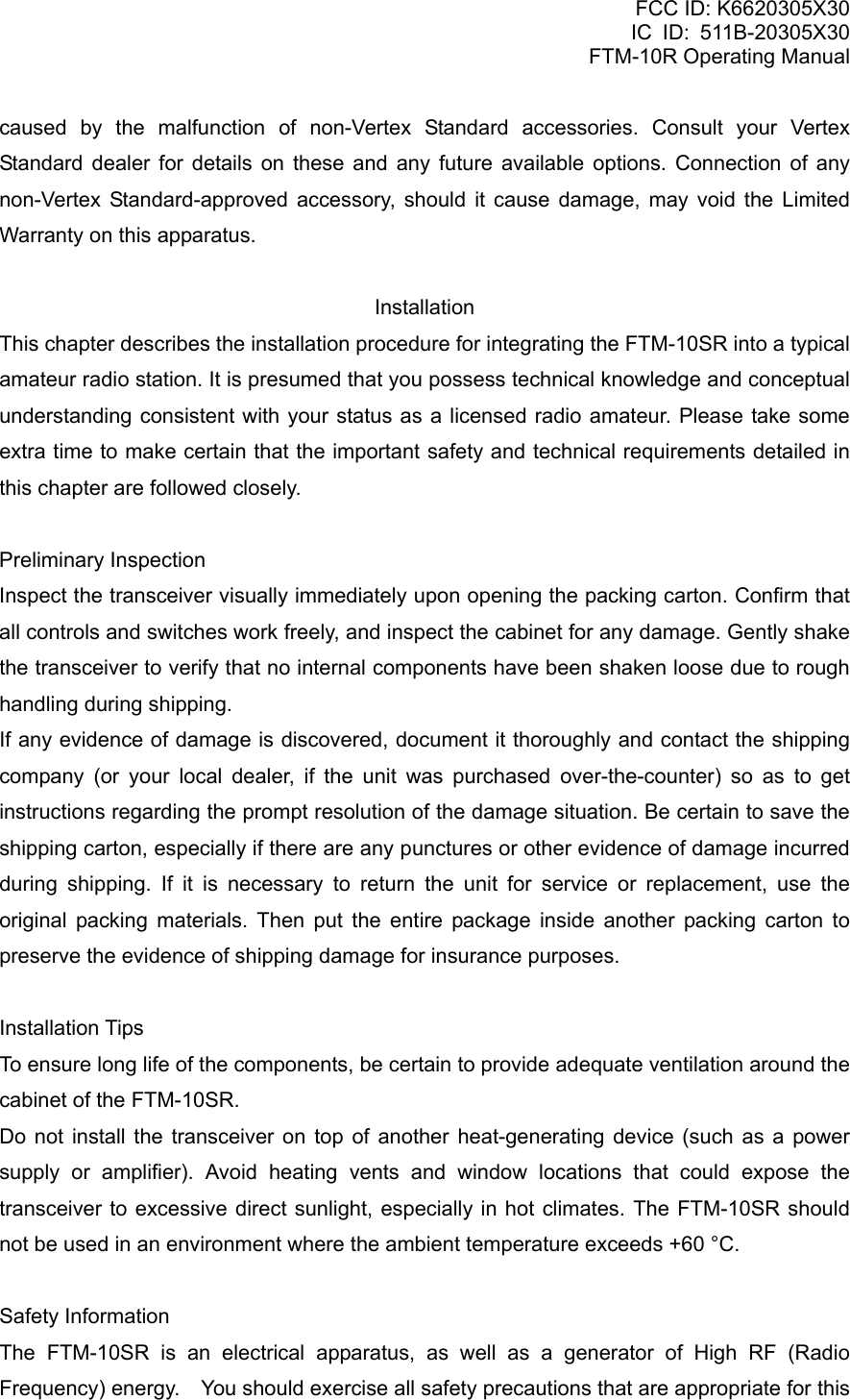
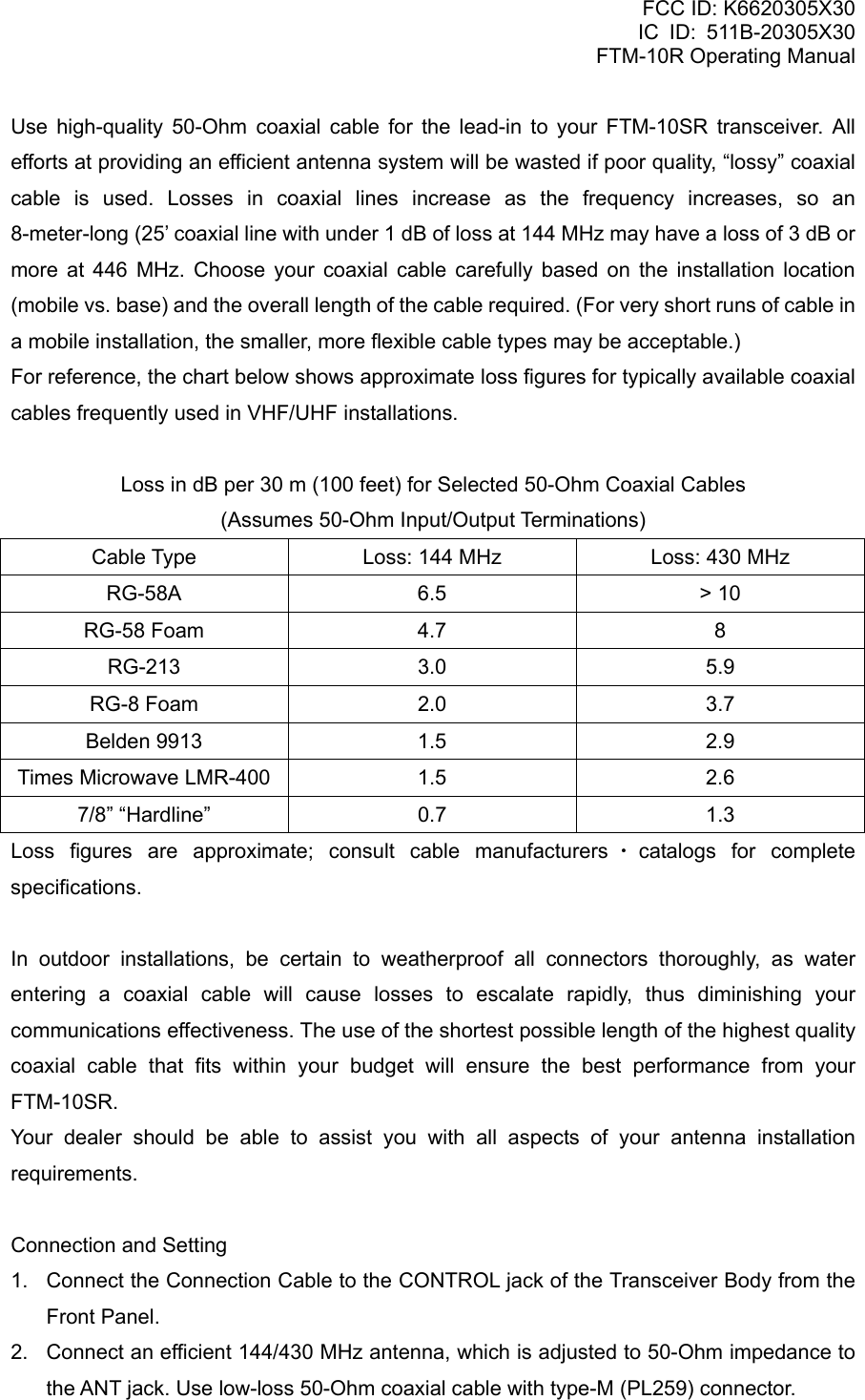
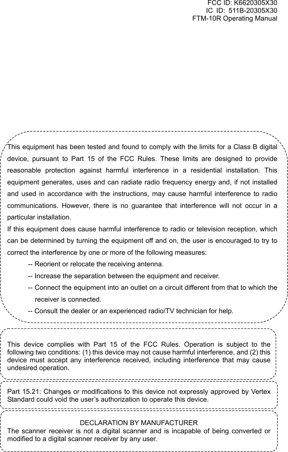
![FCC ID: K6620305X30 IC ID: 511B-20305X30 FTM-10R Operating Manual 1. Remove the four screws securing the Front Panel and then remove the panel from the transceiver body (Figure 1). 2. Disconnect the 8-pin modular plug from the transceiver (Figure 2). 3. Remove the screw affixing the Straight Sub Panel, and then remove the Straight Sub Panel from the Front Panel (Figure 3). 4. Attach the supplied Angle Sub Panel to the Front Panel, using the previously removed screw. You may set this up in a “look-up” or “look-down” configuration depending on the mounting position of the Sub Panel. 5. Connect the 8-pin modular plug to the transceiver’s body. 6. Attach the Front Panel (with Angle Sub Panel) to the transceiver’s body, using the previously removed four screws (Figure 5). Basic Operation Receive 1. To turn the transceiver on, press and hold in the top panel [POWER] key for two seconds. When you turn the transceiver on, the applied DC voltage is displayed on the LCD for 2 seconds. Then the operating frequency will be displayed. To turn the transceiver off, press and hold in the [POWER] key for two seconds. 2. Press the front panel / keys to switch the operating band as follows: Key Æ 2 m Amateur Band (H-V) Æ 430 MHz Amateur Band (H-U) Æ FM BC Band (FM) Æ AM BC Band (AM) Æ WX Band (WX) Æ Audio Line Æ Group Memory (GRP) Æ 2 m Amateur Band (H-V) Æ Key 2 m Amateur Band (H-V) Æ Group Memory (GRP) Æ Audio LineÆ WX Band (WX) Æ AM BC Band (AM) Æ FM BC Band (FM) Æ 430 MHz Amateur Band (H-U) Æ 2 m Amateur Band (H-V) Æ * When external audio equipment, like an iPod®, is connected, an after-market cable is required. When external audio equipment is connected, the input audio level must be adjusted on the external audio equipment. H-U 430 MHz Amateur Band H-V 144 MHz Amateur Band Vertex Standard Co., Ltd. 15](https://usermanual.wiki/Yaesu-Musen/20305X30/User-Guide-805828-Page-15.png)
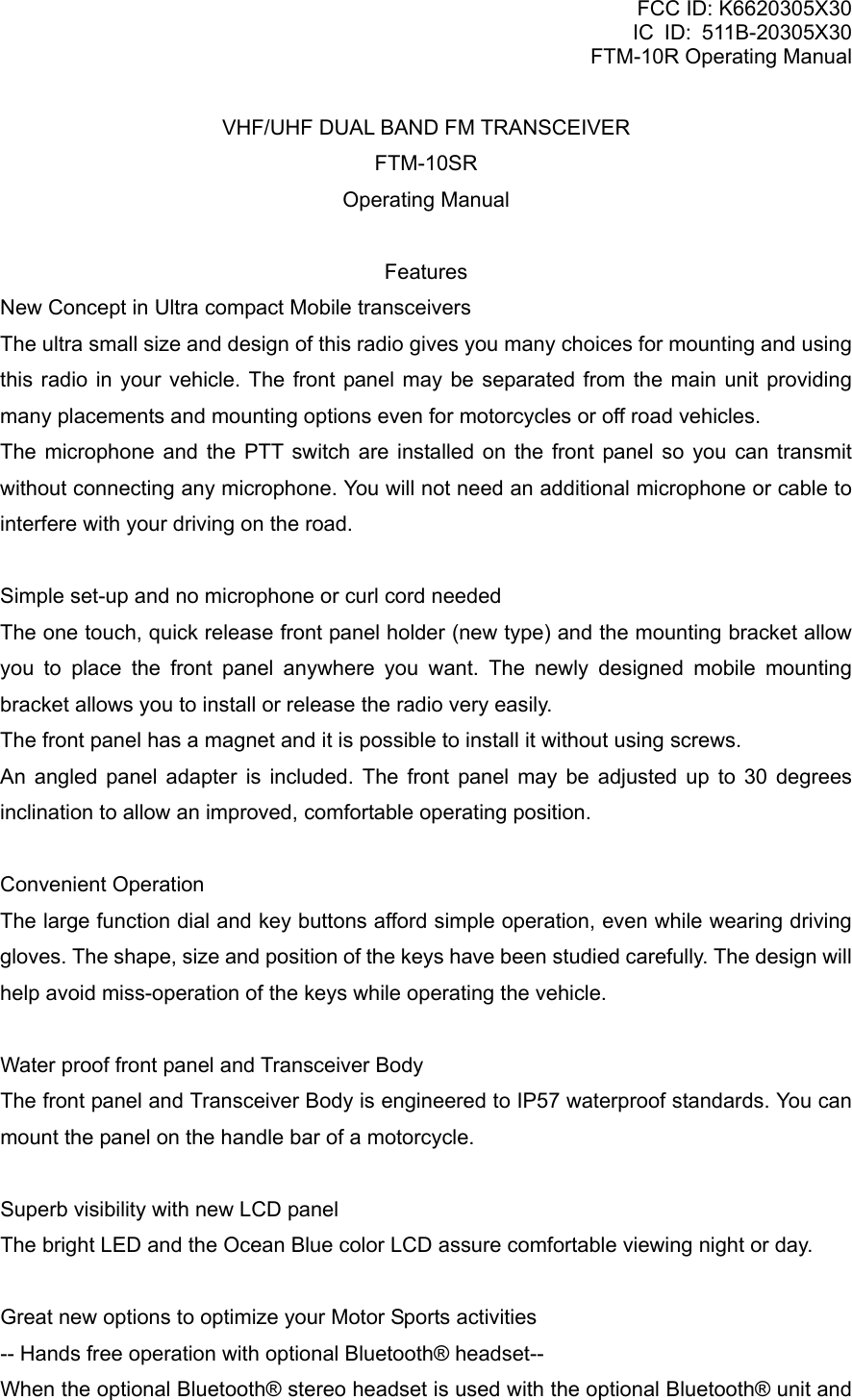
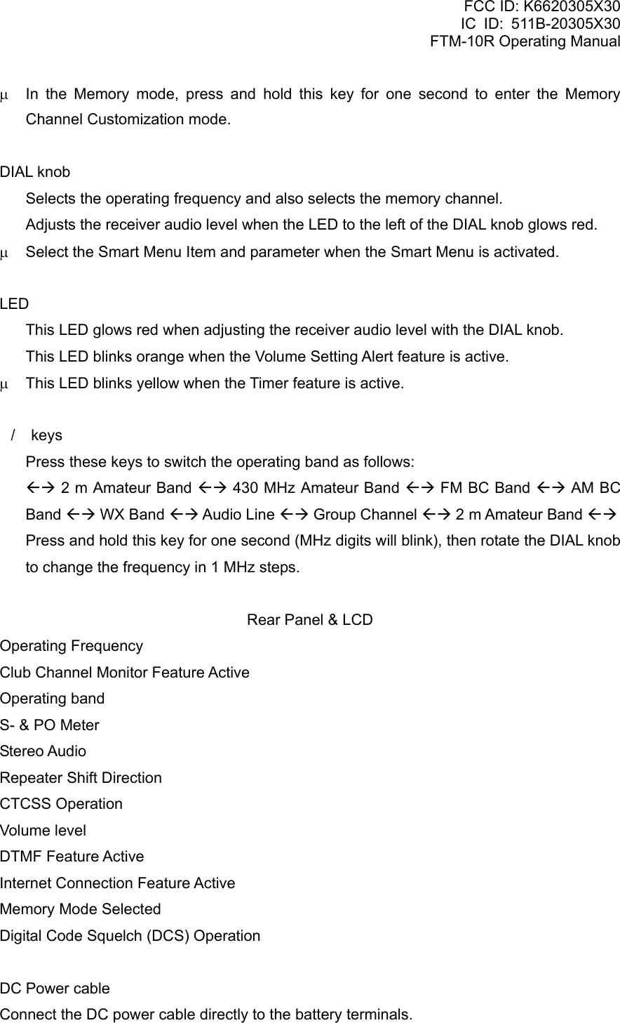
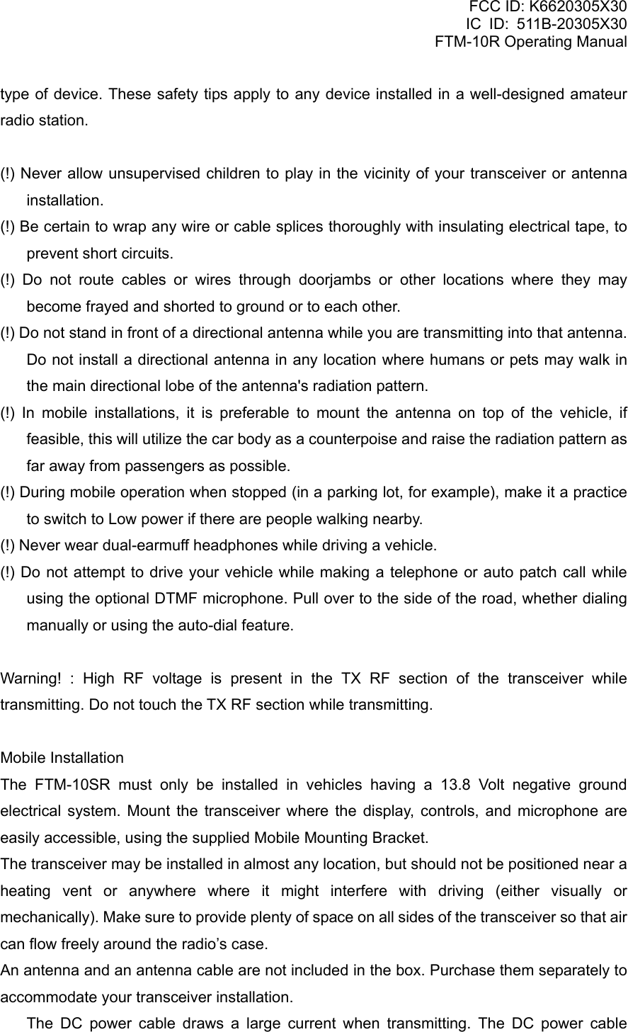
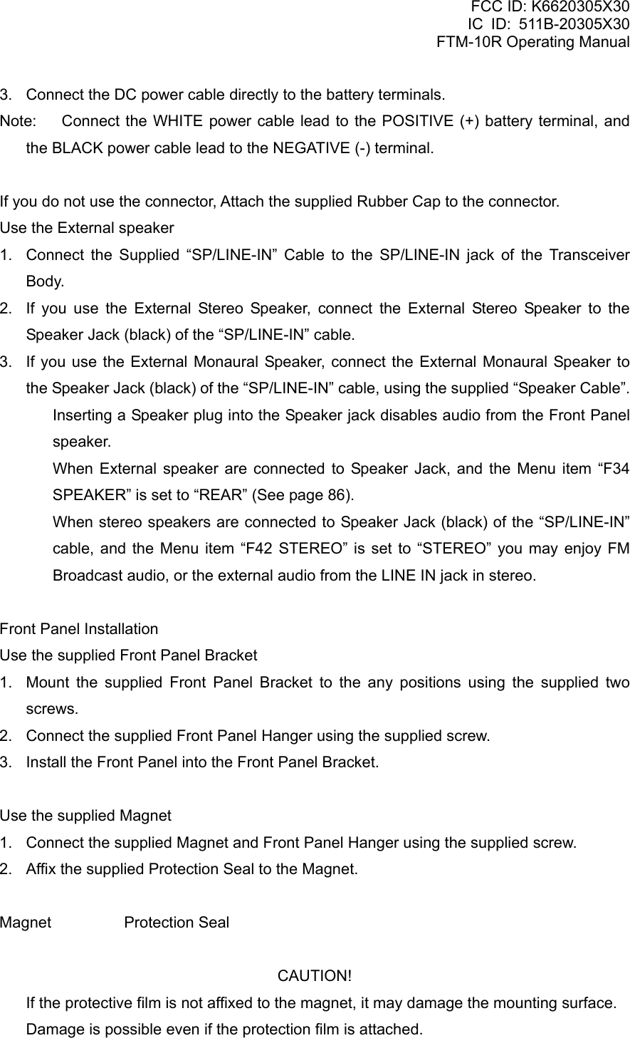
![FCC ID: K6620305X30 IC ID: 511B-20305X30 FTM-10R Operating Manual GRP Group Memory -- Audio Line WX WX Band AM AM BC Band FM FM BC Band 3. Rotating the DIAL knob tunes the frequency in pre-programmed steps. Clockwise rotation of the DIAL knob will increase the frequency; counter-clockwise rotation will lower the operating frequency. 4. Press and hold in one of the front panel / keys for one second (the 1 MHz digit will blink). Then rotate the DIAL knob to change the frequency at 1 MHz per step. This feature is extremely useful for making rapid frequency excursions over the wide tuning range of the FTM-10SR. 5. Press the [VOL/SEL] key until the red LED to the left of the DIAL knob illuminates and the volume level is displayed on the LCD. Now, the DIAL knob becomes the volume knob. 6. Rotate the DIAL knob to adjust the receiver volume. Clockwise rotation increases the audio output level. Transmission 1. Press the front panel / keys to switch the operating band to 144 MHz or 430 MHz band. 2. Press the PTT (Push To Talk) key on the front panel when the frequency is clear. Speak into the microphone on the front panel (upper left corner of the front panel) in a normal voice level. When talking around 3 feet away from the front panel microphone, the modulation may not be enough and the transmitted audio level may be lower. 3. When your transmission is complete, release the PTT key. The transceiver will revert to the receive mode. Smart Menu Features The FTM-10SR top panel / keys, and the [F] key select and enable operation of the following features: Select the function Vertex Standard Co., Ltd. 16](https://usermanual.wiki/Yaesu-Musen/20305X30/User-Guide-805828-Page-16.png)
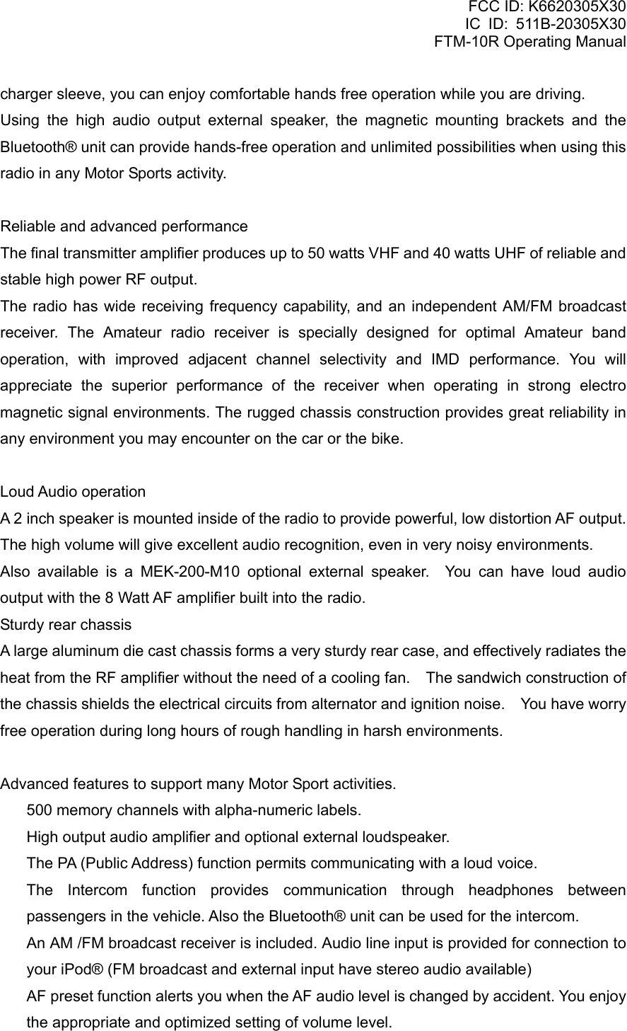
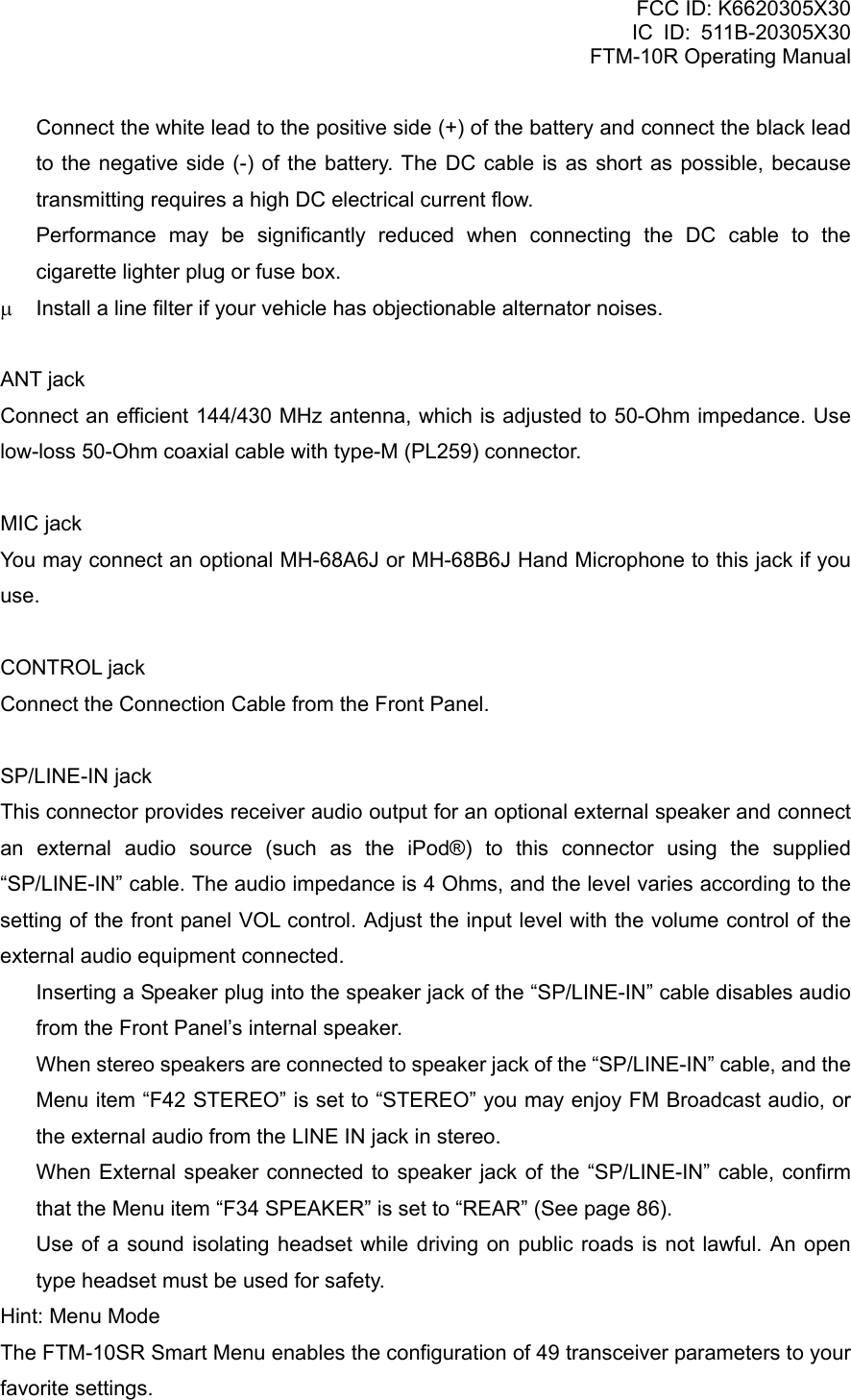
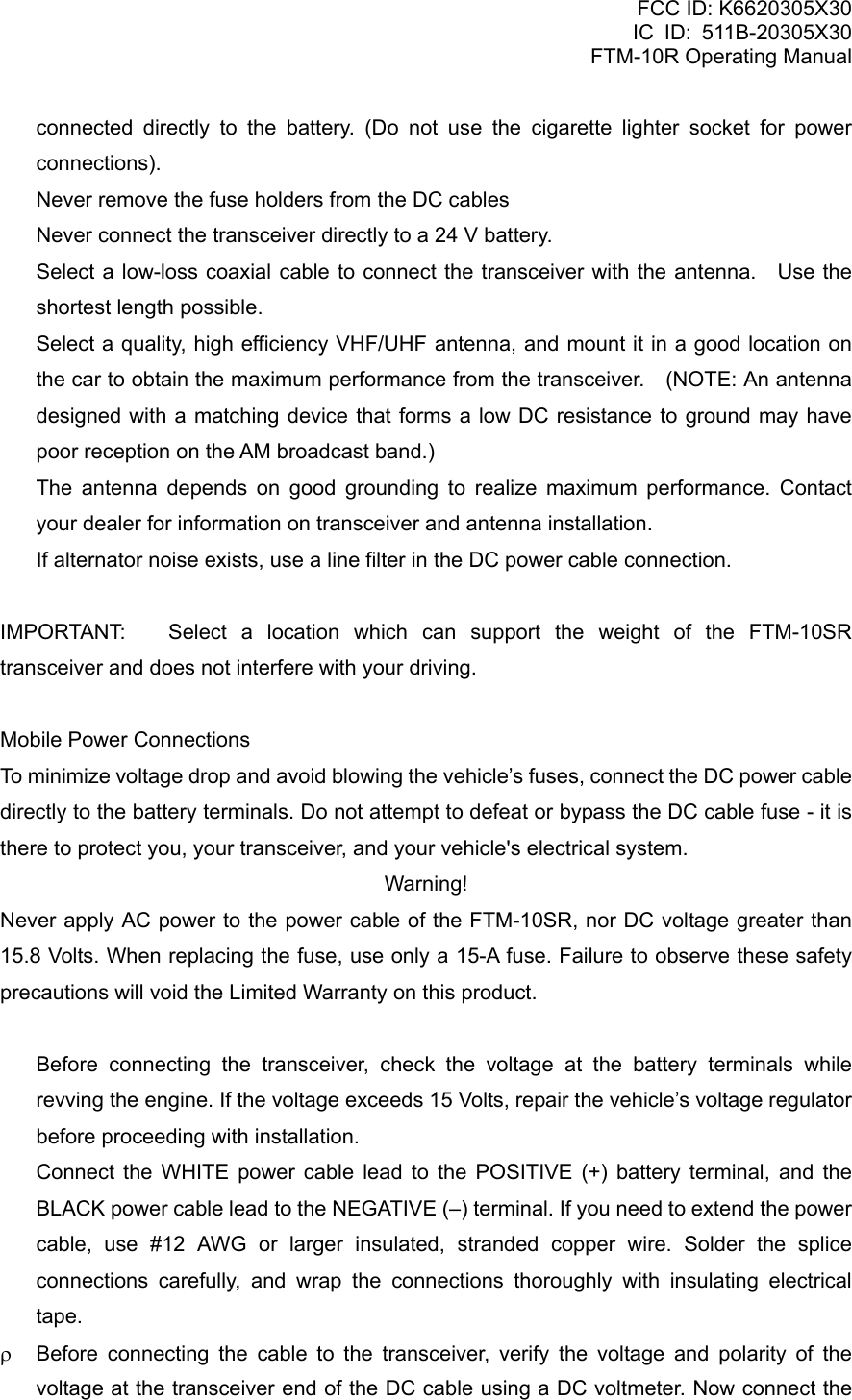
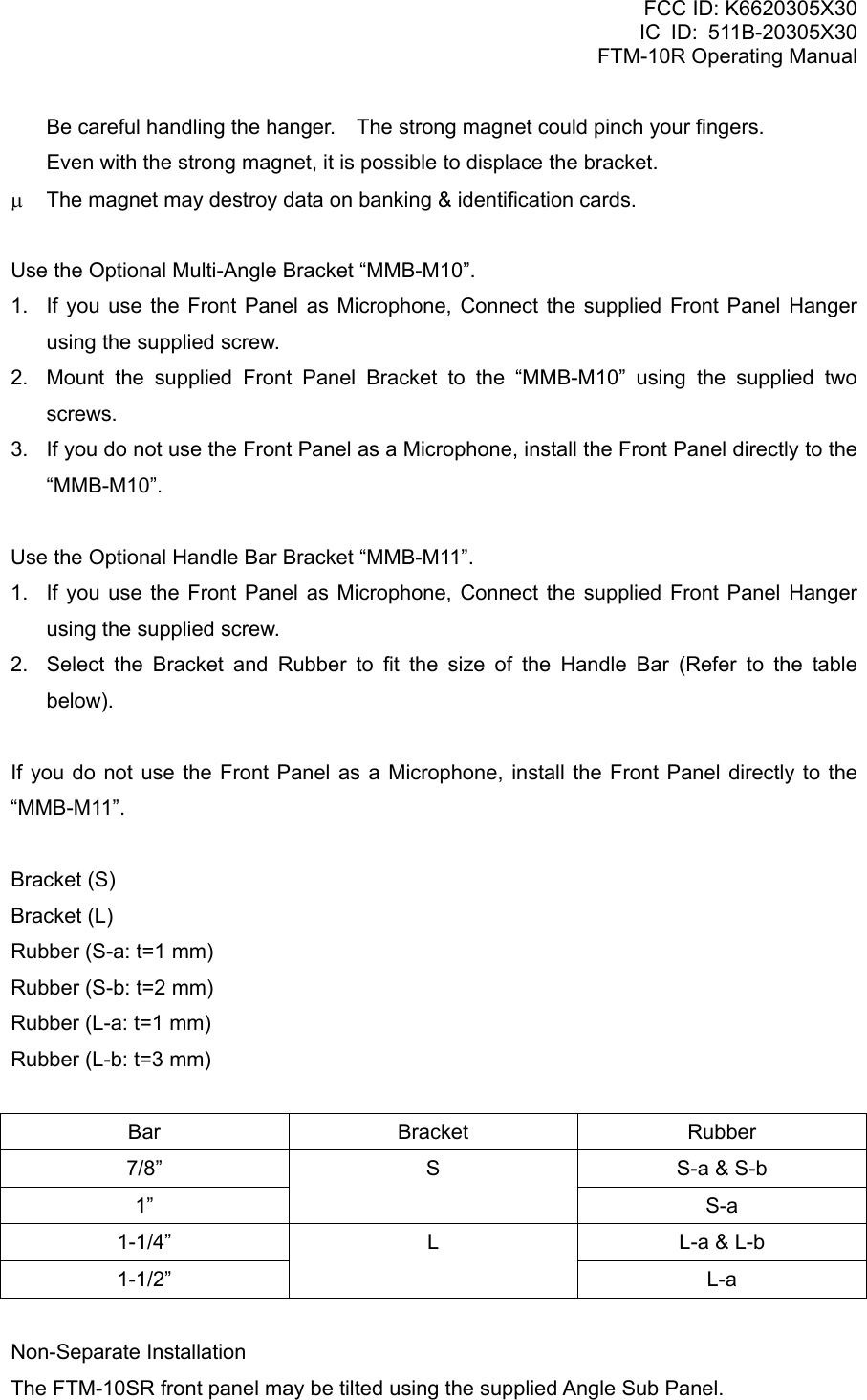
![FCC ID: K6620305X30 IC ID: 511B-20305X30 FTM-10R Operating Manual Display Function AF DUAL Press the [F] key to activate the AF Dual function which enables receiving an Amateur Band signal while listening to the signal of an FM Broadcast Station at the same time. ARTS Press the [F] key to activate the ARTS feature. DIMMER Press the [F] key to enable adjustment of the display illumination level by the DIAL knob. HORN 1 Press the PTT switch to activate the sound of a Gong Bell. HORN 2 Press the PTT switch to activate the sound of a UFO in flight. HORN 3 Press the PTT switch to activate the sound of a klaxon. HORN 4 Press the PTT switch to activate the sound of a siren. INTERCOM Press the [F] key to activate the Intercom mode. MONI Press the [F] key to disable noise and tone squelch. PA Press the PTT switch to route your amplified voice through the PA speaker. REVERSE Press the [F] key to activate the Reverse feature. SCAN Press the [F] key to activate the scanner. SQL LEVL Press the [F] key to enable adjustment of the noise squelch threshold level by the DIAL knob. SSCH Press the [F] key to activate the Smart Search. TCALL Press the [F] key to activate the 1750 Hz Tone Burst. TX POWER Press the [F] key to change the transmit power level. VOL.ITCOM Press the [F] key to change the receiver Vertex Standard Co., Ltd. 17](https://usermanual.wiki/Yaesu-Musen/20305X30/User-Guide-805828-Page-17.png)
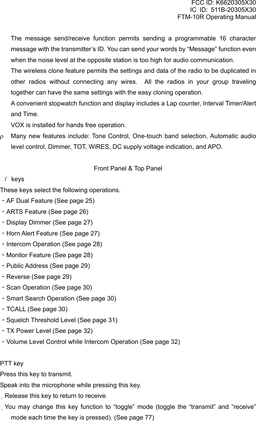
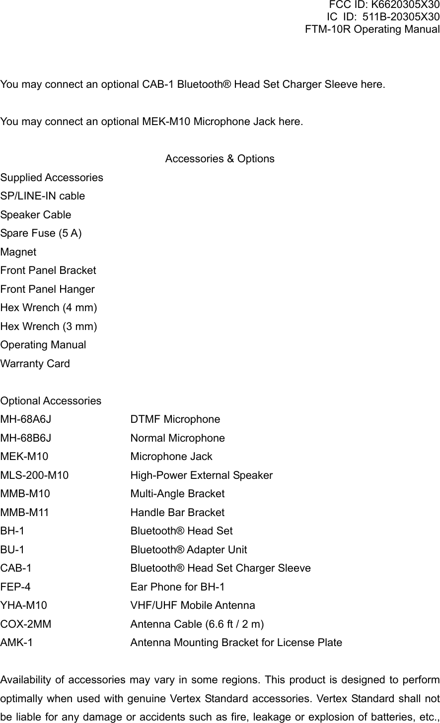
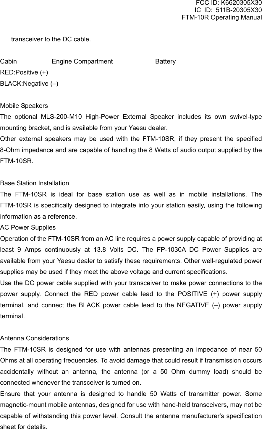
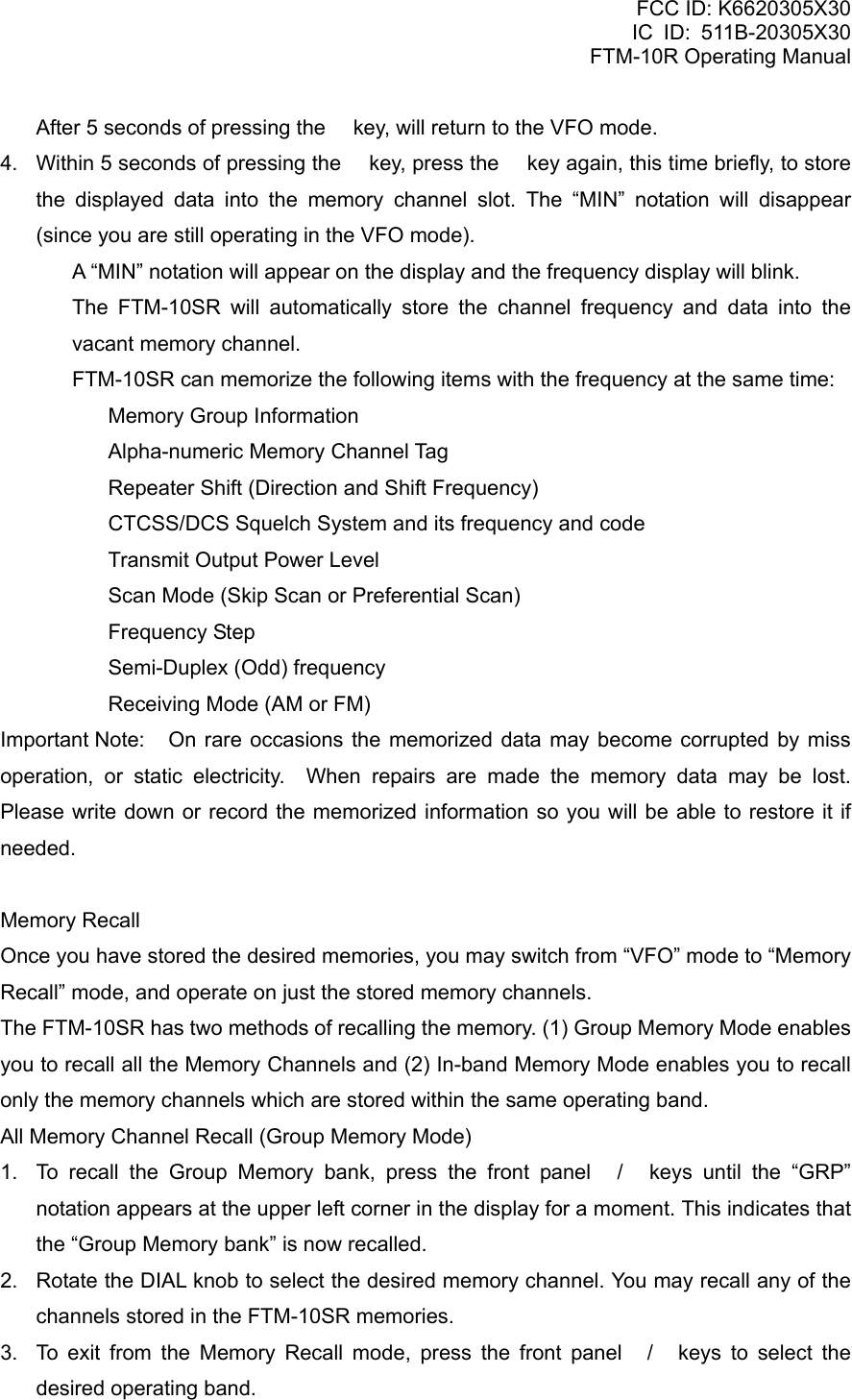
![FCC ID: K6620305X30 IC ID: 511B-20305X30 FTM-10R Operating Manual audio level of the intercom receiver. Advice: When one of the above features does not appear in the list, it is because that feature is not assigned to the top panel / keys. Please insure the Menu “F14 FKEY MOD” is set to “FNC” or “FNC+MSG”. AF Dual Function With the “AF DUAL” function, it is possible to monitor your desired amateur band frequency while receiving AM, FM broadcast or Audio from the external input jack. You may select: AM broadcast, FM broadcast, Club Channel or external line input, by changing the Menu Item “F2 AF DUAL” (The factory default is AM broadcast receiving). 1. Set the FTM-10SR to the desired amateur band frequency by the VFO or Memory channel selection. 2. Press the top panel / key to select “AF DUAL”. 3. Press the [F] key to activate the AF Dual function. By first setting the desired VFO or memory channel in step #1 above, and then starting “AF DUAL” function, both the amateur signals and the AM broadcast station will be received. 4. Rotate the DIAL knob to select the desired AM Broadcast station. You may switch the AM Broadcast Band frequency control between the VFO and Memory channel by pressing the key. When a signal is received in the amateur band, the AM Broadcast audio is muted. When the amateur band signal drops, the AF Dual function is resumed (monitor the amateur band frequency while receiving the AM broadcast). You may transmit on the frequency set in step1 by pressing the PTT key, even if the AF Dual function is activated. To disable the AF Dual function, press the front panel / keys. When the [F] key function is set to “AF DUAL” via the top panel / key, the [F] key may be used to toggle the “AF DUAL” on/off. ARTSTM The ARTS feature uses DCS signaling to inform both parties when you and another ARTS equipped station are within communications range. This may be particularly useful during Search and Rescue situations, where it is important to stay in contact with other members of your group. Both stations must set up their DCS codes to the same code number, then activate their Vertex Standard Co., Ltd. 18](https://usermanual.wiki/Yaesu-Musen/20305X30/User-Guide-805828-Page-18.png)
![FCC ID: K6620305X30 IC ID: 511B-20305X30 FTM-10R Operating Manual ARTS feature using the command appropriate for their radio. Alert ringers may be activated, if desired. Whenever you push the PTT key, or every 25 seconds after ARTS is activated, your radio will transmit a signal which includes a (subaudible) DCS code for about 1 second. If the other radio is in range, the beeper will sound (if enabled) and the display will show “IN.RANGE” otherwise the out of range display “OUT.RANGE” will be display during ARTS operation. Whether you talk or not, the polling every 25 seconds will continue until you de-activate ARTS. When ARTS is de-activated, DCS will also be deactivated (if you were not using it previously in non- ARTS operation). If you move out of range for more than one minute (four pollings), your radio will sense that no signal has been received. Three beeps will sound, and the display will revert to “OUT.RANGE” If you move back into range, your radio will again beep, and the display will change back to the “IN.RANGE” indication. During ARTS operation, your operating frequency will continue to be displayed, but no changes may be made to it or other settings. You must terminate ARTS in order to resume normal operation. This is a safety feature designed to prevent accidental loss of contact due to channel change, etc. 1. Set the FTM-10SR to the desired amateur band frequency by the VFO or Memory channel selection. 2. Set your radio and the other radio(s) to the same DCS code number per the discussion on page 65. 3. Press the top panel / key to select “ARTS”. 4. Press the [F] key. You will observe the “OUT.RANGE” display on the LCD. The ARTS operation has now commenced. 5. Every 25 seconds, your radio will transmit a “polling” call to the other station. When that station responds with its own ARTS polling signal, the display will change to “IN.RANGE” to confirm that the other station’s polling code was received in response to yours. 6. When the [F] key function is set to “ARTS” via the top panel / key, the [F] key may be used to toggle the “ARTS” on/off. Dimmer function You may adjust the display dimmer level. 1. Press the top panel / key to select “DIMMER”. 2. Press the [F] key. Vertex Standard Co., Ltd. 19](https://usermanual.wiki/Yaesu-Musen/20305X30/User-Guide-805828-Page-19.png)
![FCC ID: K6620305X30 IC ID: 511B-20305X30 FTM-10R Operating Manual 3. Rotate the DIAL knob to select a comfortable brightness level. DIMMER 1 ÅÆ DIMMER 2 ÅÆ DIMMER 3 ÅÆ DIMMER 4 ÅÆ DIMMER 5 ÅDim BrightÆ 4. Within two seconds of selecting the brightness level, save the new setting and return to the VFO or Memory Channel mode. When the [F] key function is set to “DIMMER” via the top panel / key, the [F] key is used as the Dimmer Level control key. Horn Alert feature (Default “OFF”) The Horn Alert feature outputs one of four unique sounds to the transceiver’s speaker. When an optional MLS-200-M10 External Speaker is connected, the FTM-10SR transceiver may be used as an 8 watt Horn Alert. 1. Press the top panel / key to select one of the four functions described below: HORN 1: Sounds a Gong Bell. HORN 2: Sounds a flight sound of a UFO. HORN 3: Sounds a klaxon. HORN 4: Sounds an ambulance siren. 2. Press the [F] key to activate the Horn Alert feature. When the Horn Alert function is activated, the volume level graphic will be displayed on LCD. 3. Press the PTT key. You may change the PTT key function via Menu Item “F24 PTT MODE”. MOMENT: While pressing the PTT key, the audio is output from the speaker (factory default). TOGGLE: Once the PTT key is pressed the audio is output from the speaker, and when the PTT key is pressed once again, the audio output is off. The unique sound, which was selected in step 1 above, will be output from the speaker. The “HORN OUT” notation appears in the display while the Horn Alert is activated. Press the [VOL/SEL] key to adjust the volume (AF level) of the Horn Alert output. While the RED LED is on, the volume level can be adjusted with the dial knob. To disable the Horn Alert feature, repeat steps 1 and 2 above. Intercom Function Intercom operation is possible with the FT-10R, by installing the optional Bluetooth ョ Adapter unit “BU-1” in the radio and using the optional Bluetooth® Headset “BH-1” When Vertex Standard Co., Ltd. 20](https://usermanual.wiki/Yaesu-Musen/20305X30/User-Guide-805828-Page-20.png)
![FCC ID: K6620305X30 IC ID: 511B-20305X30 FTM-10R Operating Manual operating in a very noisy environment, (for example, a loud exhaust or engine noise, or inside an off-road vehicle) communication with a fellow passenger is possible using the Bluetooth® intercom feature. 1. Press the top panel / key to select “INTERCOM”. 2. Press the [F] key to activate the Intercom function. When the Intercom function is activated, the volume level graphic will be displayed on LCD. You may switch the receiver audio volume level between “High” and “Low” via the “VOL.ITCOM” function described below. When the Intercom function is activated, the internal speakers (front panel and main chassis) are disabled. To disable the Intercom function, repeat steps 1 and 2 above. When set the [F] key function to “INTERCOM” via the top panel / key, the [F] key to be used as the Intercom feature on/off key. Important Notice! Use of a sound-isolating headset while driving on public roads is not lawful and hazardous. An open type headset must be used for safety. Monitor feature The Monitor permits disabling the noise and tone squelch systems temporarily. When the received signal is weak and the sound from the speaker is intermittent, use this function to over-ride the squelch and hear the received signal. 1. Press the top panel / key to select “MONI”. 2. Press the [F] key. The noise and tone squelch are disabled while pressing the [F] key. When the [F] key function is set to “MONI” via the top panel / key, the [F] key may be used as the “Monitor” key. Public Address feature The Public Address feature enables the output of your voice to the transceiver’s speaker. When an optional MLS-200-M10 External Speaker is connected, the FTM-10SR allows the transceiver to be used as an 8 W Public Address system. 1. Press the top panel / key to select “PA”. 2. Press the [F] key to activate the Public Address feature. 3. Press the PTT key, and speak into the microphone in a normal voice level. Vertex Standard Co., Ltd. 21](https://usermanual.wiki/Yaesu-Musen/20305X30/User-Guide-805828-Page-21.png)
![FCC ID: K6620305X30 IC ID: 511B-20305X30 FTM-10R Operating Manual You may select the PTT key function via Menu Item “F24 PTT MODE”. MOMENT: While pressing the PTT key, the audio is output from the speaker (factory default). TOGGLE: Once the PTT key is pressed the audio is output from the speaker, and when the PTT key is pressed once again, the audio output is off. Your voice is output to the speaker. The “P A” notation appears in the display while the Public Address is activated. Press the [VOL/SEL] key to adjust the volume (AF level) of the PA output. While the RED LED is on, the volume level can be adjusted with the dial knob. CAUTION! When the function is changed to the radio mode, the volume level remains the same. Please be careful about the volume level setting. You may adjust the audio output level by rotating the DIAL knob. To disable the Public Address feature, repeat steps 1 and 2 above. Note: Please be careful that the PA function does not cause any inconvenience or disturbance for others in your area. Reverse feature The Reverse feature reverses transmit and receive frequencies while working through a repeater. It is often helpful to be able to check the uplink (input) frequency of a repeater, to see if the calling station is within direct (“Simplex”) range. 1. Press the top panel / key to select “REVERSE”. 2. Press the [F] key to activate the Reverse feature. The “–” or “+” or “–+” icon will blink while “Reverse” shift is activated. 3. Press the [F] key again to revert to the “Normal” shift direction. Scan feature 1. Press the top panel / key to select “SCAN”. 2. Press the [F] key to initiate upward scanning. When the scanner encounters a signal strong enough to open the squelch, the scanner will halt for five seconds, and then resume scanning. 3. To stop the scanner, press the [F] or PTT key. Vertex Standard Co., Ltd. 22](https://usermanual.wiki/Yaesu-Musen/20305X30/User-Guide-805828-Page-22.png)
![FCC ID: K6620305X30 IC ID: 511B-20305X30 FTM-10R Operating Manual When the [F] key function is set to “SCAN” via the top panel / key, the [F] key may be used as the scan start/stop command key. If you want to change the direction of the scan while it is underway, rotate the DIAL knob one click in the opposite direction (in this case, one click counter-clockwise). You will see the scanner reverse direction and scan down in frequency. The decimal point of the frequency display while the Scan is activated. You may select the Scan Resume mode via the Menu Item “F26 RESUME”. When you start the scanner in the memory mode, only the memorized memory channels will be scanned Smart SearchTM Operation The Smart Search feature allows you to load frequencies automatically according to where activity is encountered by your radio. When Smart Search is engaged, the transceiver will search above and below your current frequency, storing active frequencies as it goes (without stopping on them even momentarily). These frequencies are stored into a special Smart Search memory bank, consisting of 31 memories (15 above the current frequency, 15 below the current frequency, plus the current frequency itself). All channels where activity is present will be loaded into the Smart Search memories. The search will stop after one sweep in each direction, whether or not all 31 memories are filled. Storing Smart Search Memories 1. Set the radio to the VFO mode. Be sure that you have the Squelch adjusted properly (so that band noise is quieted). 2. Press the top panel / key to select “SSCH”. 3. Press the [F] key to initiate upward scanning. 4. As active channels are detected, they will automatically be stored into the Smart Search memory bank without causing the sweep to halt. If you want to change direction of the Smart Search while it is underway, rotate the DIAL knob one click in the opposite direction (in this case, one click counter-clockwise). You will see the scanner reverse direction and Smart Search down in frequency. 5. The Smart Search scan will eventually terminate, and the LCD will revert to Smart Search Memory Channel “<C>”. 6. To recall the Smart Search memories, just rotate the DIAL knob (or press the microphone’s [UP]/[DWN] key) to choose from among the Smart Search memories. 7. Press the front panel key to return to VFO mode with the current frequency of the Smart Search memory. Note: 1) Smart Search is a great tool when visiting a city for the first time. You don’t Vertex Standard Co., Ltd. 23](https://usermanual.wiki/Yaesu-Musen/20305X30/User-Guide-805828-Page-23.png)
![FCC ID: K6620305X30 IC ID: 511B-20305X30 FTM-10R Operating Manual need to spend hours looking up repeater frequencies from a reference guidebook. Just ask your FTM-10SR where the action is! 2) The Smart Search memories are so-called “soft” memories. They will be lost if you initiate a new Smart Search sweep of the band, or if you switch to the VFO or Memory mode. Squelch Level Adjust Adjust the squelch level to mute the noise from the speaker when no signal is being received. 1. Press the top panel / key to select “SQL LEVL”. The current squelch level will be displayed. 2. Press the [F] key. 3. Rotate the DIAL knob just to the point where the noise is silenced and the front panel green “BUSY” indicator turns off. Available selections are: Amateur Bands: OFF ÅÆ MIN ÅÆ 01 ~ 06 ÅÆ MAX (Default: 01) AM/FM Broadcast Bands: OFF ÅÆ MIN ÅÆ 01 ~ 03 ÅÆ MAX (Default; AM: 01, FM: 02) If the DIAL knob is set further clockwise, sensitivity to weak signals is reduced. 4. Press the [F] key to save the new setting and return to the VFO or Memory Channel mode. When the [F] key function is set to “SQL LEVL” via the top panel / key, the [F] key may be used as the Squelch Level control key. TCALL (Default “OFF”) You may enable TCALL if the repeaters in your country require a 1750-Hz burst tone for access. 1. Press the top panel / key to select “TCALL”. 2. Press the [F] key. The transmitter will automatically be activated, and a 1750-Hz audio tone will be superimposed on the carrier. 3. You may release the [F] key, and use the PTT key for activating the transmitter thereafter. TX Power Select Vertex Standard Co., Ltd. 24](https://usermanual.wiki/Yaesu-Musen/20305X30/User-Guide-805828-Page-24.png)
![FCC ID: K6620305X30 IC ID: 511B-20305X30 FTM-10R Operating Manual Set the TX Power level to reduce battery drain and use the lowest power necessary to maintain reliable communications. 1. Press the top panel / key to select “TX POWER”. 2. Press the [F] key repeatedly to select the desired transmit power level. You may set the transmit power level for the 144 MHz and 430 MHz band individually. HIGH MID LOW 144 MHz 10 W 3 W 0.5 W 430 MHz 7 W 3 W 0.5 W 3. Two seconds after selecting the transmitter power level, the new setting is automatically saved and the radio returns to the VFO or Memory Channel mode. When the [F] key function is set to “TX POWER” via the top panel / key, the [F] key may be used as the Transmit Power Level control key. Intercom Volume Control 1. Press the top panel / key to select “VOL.ITCOM”. 2. Press the [F] key to change the Intercom receiver audio volume level between “HIGH” and “LOW”. 3. Two seconds after selecting the Intercom receiver audio volume level, the new setting is automatically saved and the radio returns to the VFO or Memory Channel mode. When the [F] key function is set to “VOL.ITCOM” via the top panel / key, the [F] key may be used as the Transmit Power Level control key. Memory Operation Many memory resources are available on the FTM-10SR. A total of 500 memories are available, and each may be appended with an alphanumeric label of up to eight characters, for quick channel recognition. The FTM-10SR has two methods of the Memory Mode; (1) Group Memory Mode enables the recall of all memory channels, and (2) In-band Memory Mode enables the recall of memory channels, which are stored in the same operating band. Memory Storage To store a frequency into memory: 1. Press the front panel / keys to select the desired operating band. 2. Rotate the DIAL knob to select the desired operating frequency. 3. Press and hold in the key for one second. A “MIN” notation will appear on the display and the frequency display will blink. Vertex Standard Co., Ltd. 25](https://usermanual.wiki/Yaesu-Musen/20305X30/User-Guide-805828-Page-25.png)
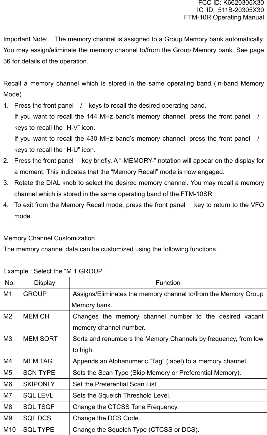
![FCC ID: K6620305X30 IC ID: 511B-20305X30 FTM-10R Operating Manual M11 TX SHIFT Stores an independent (in band) transmit frequency (Odd Split). M12 TX POWER Change the Transmitter Power Level. M13 DELETE Deletes memorized data (except CLUB memory channel). Memory Group Bank In the FTM-10SR, the memory channel is assigned to the Group Memory Bank automatically. The Group Memory Bank can be recalled by pressing the front panel / key (A “GRP” notation appears at the upper left corner in the display for a moment.). You may observe the Group Memory Bank between the Audio Line and 2 m Amateur Band. You may assign/eliminate the memory channel to/from the Group Memory Bank. The eliminated memory channel is only recalled by recalling the memory channel, which is stored in the same operating band. To eliminate the memory channel from the Group Memory bank: 1. Recall the memory channel you wish to delete from the Group Memory Bank. 2. Press and hold the key for one second to enter the Memory Channel Customization mode. 3. Rotate the DIAL knob to select Menu Item “M1 GROUP”. Press the key briefly, then rotate the DIAL knob to select “OFF”; this deletes the current memory channel from the Group Memory bank. 4. Press the [VOL/SEL] key to save the new setting and return to the memory recall mode. To re-assign the eliminated memory channel into the Group Memory bank: 1. Press the front panel key to switch the VFO mode, if needed. 2. Press the front panel / keys to recall the operating band which is the same band as the eliminated memory channel. 3. Press the front panel key again to switch the “Memory Recall” mode, and then rotate the DIAL knob to select the memory channel you wish to re-assign into the Group Memory bank. 4. Press and hold the key for one second to enter the Memory Channel Customization mode. 5. Rotate the DIAL knob to select Menu Item “M1 GROUP”. 6. Press the key briefly, then rotate the DIAL knob to select “ON”; the current memory channel will be assigned into the Group Memory bank. 7. Press the [VOL/SEL] key to save the new setting and return to the memory recall mode. Vertex Standard Co., Ltd. 28](https://usermanual.wiki/Yaesu-Musen/20305X30/User-Guide-805828-Page-28.png)
![FCC ID: K6620305X30 IC ID: 511B-20305X30 FTM-10R Operating Manual Memory Channel Number Change You may change the memory channel number to a desired vacant memory channel manually. 1. Recall the memory channel on which you wish to change the Memory Channel number. 2. Press and hold the key to enter the Memory Channel Customization mode. 3. Rotate the DIAL knob to select Menu Item “M2 MEM CH”. 4. Press the key briefly. The current memory channel number will appear in the display. 5. Press and hold the key for one second. 6. Rotate the DIAL knob to select the desired memory channel number. If you decide to cancel the Memory Channel Number Change, press the [VOL/SEL] key. If the channel number is blinking, that channel is currently “occupied” by other frequency data, and you should not select that channel. 7. Press and hold the key to change the Memory Channel Number. 8. Press the [VOL/SEL] key to save the new setting and return to the memory recall mode. Memory Channel Sort You may sort and renumber the Memory Channels by frequency, from low to high: 1. Press the front panel key to switch the Memory Recall mode, if needed. 2. Press and hold the key for one second to enter the Memory Channel Customization mode. 3. Rotate the DIAL knob to select Menu Item “M3 MEM SORT”. 4. Press the key briefly, to display the confirmation message (“SORT Y”) on the LCD. If you decide to cancel the Memory Channel Sort, press the [VOL/SEL] key. 5. Press and hold the key for one second to display the message (“SORTING”) on the LCD, then the FTM-10SR is reset automatically and sorting is complete. Labeling Memory You may wish to append an Alphanumeric “Tag” (label) to a memory or memories, to aid in recollection of the channel’s use (such as a club name, etc.). This is easily accomplished using the Set (Menu) mode. 1. Recall the memory channel on which you wish to append a label. 2. Press and hold the key for one second to enter the Memory Channel Customization mode. 3. Rotate the DIAL knob to select Menu Item “M4 MEM TAG”. 4. Press the key briefly, then rotate the DIAL knob to select “ALPHA”. 5. Press and hold the key for one second to display the previous label. Vertex Standard Co., Ltd. 29](https://usermanual.wiki/Yaesu-Musen/20305X30/User-Guide-805828-Page-29.png)
![FCC ID: K6620305X30 IC ID: 511B-20305X30 FTM-10R Operating Manual 6. Press the PTT key to clear any previous label, if needed. 7. Rotate the DIAL knob to select the first digit of the desired label. 8. Press the key to move to next character. 9. Repeat steps 6 and 7 to program the remaining letters, numbers, or symbols of the desired label. A total of eight characters may be used in the creation of a label. 10. If you make a mistake, press the key to backspace the cursor, then re-enter the correct letter, number, or symbol. Press the PTT key to delete all data after the cursor that may have been previously stored erroneously. 11. When you have programmed a label that is under eight characters, press and hold in the key for one second, until the “ALPHA” notation appears. 12. Press the [VOL/SEL] key to save the label and return to the memory recall mode. The label (Alpha-Numeric Tag) will now be displayed. To disable the Alpha-Numeric Tag (enabling the frequency display): 1. Recall the memory channel on which you wish the frequency to display. 2. Press and hold the key for one second to enter the Memory Channel Customization mode. 3. Rotate the DIAL knob to select Menu Item “M4 MEM TAG”. 4. Press the key briefly. Then, rotate the DIAL knob to select “FREQ”. 5. Press the [VOL/SEL] key to return to the memory recall mode. The memory channel frequency will now be displayed. Scan Type The FTM-10SR has two methods of performing Memory Channel Scan; (1) All Memory Channel Scanning and (2) Scanning only memory channels which are selected via the Skip/Preferential memory setting (see next step). 1. Press the front panel key to switch the Memory mode, if needed. 2. Press and hold the key for one second to enter the Memory Channel Customization mode. 3. Rotate the DIAL knob to select Menu Item “M5 SCN TYPE”. 4. Press the key briefly. 5. Rotate the DIAL knob to select desired Scan Type: ALL MEM: The FTM-10SR scans on all Memory Channels. ONLY MEM: The FTM-10SR scans only the memory channels that are appended with the “ONLY” flag via the Skip/Preferential memory setting. Vertex Standard Co., Ltd. 30](https://usermanual.wiki/Yaesu-Musen/20305X30/User-Guide-805828-Page-30.png)
![FCC ID: K6620305X30 IC ID: 511B-20305X30 FTM-10R Operating Manual 6. Press the [VOL/SEL] key to return to the memory recall mode. The memory channel frequency will now be displayed. Skip/Preferential Scan Setting The FTM-10SR allows you to set up a “Preferential Scan List”. You can “flag” channels within the memory system. When you initiate the Preferential Memory Scan, only “flagged” channels will be scanned. 1. Recall the memory channel that you wish to skip. (or Preferential Memory Channel). 2. Press and hold the key for one second to enter the Memory Channel Customization mode. 3. Rotate the DIAL knob to select Menu Item “M6 SKIPONLY”. 4. Press the key briefly. 5. Rotate the DIAL knob to select the desired Scan Type: SKIP: This memory channel is skipped during memory channel scans. ONLY: This memory channel scans during preferential memory scans. OFF: This memory channel scans during memory channel scan. 6. Press the [VOL/SEL] key to return to the memory recall mode. The memory channel frequency will now be displayed. Squelch Level The FTM-10SR allows setting the squelch threshold level. 1. Press the front panel key to switch the Memory mode, if needed. 2. Press and hold the key for one second to enter the Memory Channel Customization mode. 3. Rotate the DIAL knob to select Menu Item “M7 SQL LEVL”. 4. Press the key briefly. Then rotate the DIAL knob to select the desired squelch threshold level (“SQL OFF” ~ “SQL MAX”). 5. Press the [VOL/SEL] key to save the new setting and return to the memory recall mode. CTCSS frequency The FTM-10SR enables you to change the CTCSS Tone frequency. 1. Recall the memory channel on which you wish to change the CTCSS Tone Frequency. 2. Press and hold the key for one second to enter the Memory Channel Customization mode. 3. Rotate the DIAL knob to select Menu Item “M8 SQL TSQF”. 4. Press the key to display the current CTCSS Tone Frequency. Vertex Standard Co., Ltd. 31](https://usermanual.wiki/Yaesu-Musen/20305X30/User-Guide-805828-Page-31.png)
![FCC ID: K6620305X30 IC ID: 511B-20305X30 FTM-10R Operating Manual 5. Rotate the DIAL knob to select desired CTCSS Tone Frequency. 6. Press the [VOL/SEL] key to save the new setting and return to the memory recall mode. CTCSS Tone Frequency (Hz) DCS code The FTM-10SR enables you to change the DCS Tone Code. 1. Recall the memory channel on which you wish to change the DCS code. 2. Press and hold the key for one second to enter the Memory Channel Customization mode. 3. Rotate the DIAL knob to select Menu Item “M9 SQL DCS”. 4. Press the key to display the current DCS Code. 5. Rotate the DIAL knob to select desired DCS Tone Code. 6. Press the [VOL/SEL] key to save the new setting and return to the memory recall mode. DCS Code CTCSS/DCS Operation The FTM-10SR enables you to change the CTCSS/DCS operation (CTCSS/DCS mode, CTCSS Tone frequency, and DCS Tone Code) that was set previously. 1. Recall the memory channel on which you wish to change the CTCSS/DCS operation. 2. Press and hold the key for one second to enter the Memory Channel Customization mode. 3. Rotate the DIAL knob to select Menu Item “M10 SQL TYPE”. 4. Press the key to display the current CTCSS/DCS operation mode. 5. Rotate the DIAL knob to select desired CTCSS/DCS operation mode. TONE ENC: Activates the CTCSS Encoder TONE SQL: Activates the CTCSS Encoder/Decoder REV TONE: Activates the Reverse CTCSS Decoder (Mutes receiver when matching tone is received) DCS: Activates the Digital Coded Encoder/Decoder OFF: Disable the CTCSS/DCS operation 6. Press the [VOL/SEL] key to save the new setting and return to the memory recall mode. Storing Independent Transmit Frequency (Odd Split) All memories can store an independent (in band) transmit frequency. The FTM-10SR has two methods of the Storing Independent Transmit Frequency; (1) Using the Standard Repeater Shift and (2) Using the Odd Split Memory for operation on repeaters Vertex Standard Co., Ltd. 32](https://usermanual.wiki/Yaesu-Musen/20305X30/User-Guide-805828-Page-32.png)
![FCC ID: K6620305X30 IC ID: 511B-20305X30 FTM-10R Operating Manual with non-standard shift. Using the Standard Repeater Shift 1. Recall the memory channel on which you wish to store the Independent Transmit Frequency. 2. Press the key to enter the memory mode. Then recall the memory channel on which you wish to store the Independent Transmit Frequency. 3. Press and hold the key for one second to enter the Memory Channel Customization mode. 4. Rotate the DIAL knob to select Menu Item “M11 TX SHIFT”. 5. Press the key briefly. 6. Rotate the DIAL knob to select desired shift direction. Available selections are “RPTR –”, “RPTR +”, and “SIMPLEX”. 7. Press the [VOL/SEL] key to save the new setting and return to the memory recall mode. Whenever you recall a memory which contains independently stored transmit and receive frequencies, the “-+” indication will appear on the display. Using the Odd Split Memory 1. In VFO mode, tune to your desired transmit frequency. (Your transmit frequency should be in the same band as the receive frequency). 2. Press the key to enter the memory mode. Then recall the memory channel on which you wish to store the Independent Transmit Frequency. 3. Press and hold the key for one second to enter the Memory Channel Customization mode. 4. Rotate the DIAL knob to select Menu Item “M11 TX SHIFT”. 5. Press the key briefly. 6. Rotate the DIAL knob to select “S-DUPLEX”. 7. Press the [VOL/SEL] key to save the new setting and return to the memory recall mode. Whenever you recall a memory which contains independently stored transmit and receive frequencies, the “–+” indication will appear on the display. Transmitter Power Level The FTM-10SR enables you to set the Transmitter Power Level for each memory channel individually. 1. Recall the memory channel on which you wish to set the Transmitter Power Level. 2. Press and hold the key for one second to enter the Memory Channel Customization Vertex Standard Co., Ltd. 33](https://usermanual.wiki/Yaesu-Musen/20305X30/User-Guide-805828-Page-33.png)
![FCC ID: K6620305X30 IC ID: 511B-20305X30 FTM-10R Operating Manual mode. 3. Rotate the DIAL knob to select Menu Item “M12 TX POWER”. 4. Press the key briefly to display the current Transmitter Power Level. 5. Rotate the DIAL knob to the select desired Transmitter Power Level (“LOW”, “MID”, or “HIGH”). 6. Press the [VOL/SEL] key to save the new setting and return to the memory recall mode. HIGH MID LOW 144 MHz 10 W 3 W 0.5 W 430 MHz 7 W 3 W 0.5 W Deleting Memory You may delete the memorized data (except CLUB memory channel) of the FTM-10SR memories. 1. Recall the memory channel on which you wish to delete. 2. Press and hold the key for one second to enter the Memory Channel Customization mode. 3. Rotate the DIAL knob to select Menu Item “M13 DELETE”. 4. Press the key briefly to display the confirmation message (“DELETE Y”) on the LCD. If you decide to cancel the Memory Channel Number Change, press the [VOL/SEL] key. 5. Press and hold the key for one second. The display will revert to memory mode. Note: Once deleted, the channel data can not be recovered. Club Channel Operation The FTM-10SR has a special memory channel called “Club Channel” and the following features can be handy. The “Club Channel” is displayed at the first of the Group Memory Bank and “CLB” is indicated when the channel is recalled. The Club Channel can also be reprogrammed. Monitoring the “Club Channel” periodically. (Club Channel Monitor function) There are two (2) methods for this feature. 1. While monitoring the other memory channel, periodically checking the “Club Channel”. (See below) 2. While listening to the AM or FM broadcast stations or the external audio input signal, periodically checks the “Club Channel” (See page 62) Message transmission function (See page 46) Duplicate the memorized messages and the ID of the members registered in the radio. (Message Clone function. See page 48) Vertex Standard Co., Ltd. 34](https://usermanual.wiki/Yaesu-Musen/20305X30/User-Guide-805828-Page-34.png)
![FCC ID: K6620305X30 IC ID: 511B-20305X30 FTM-10R Operating Manual Duplicate the memory channel and other setting information to other radios. (Clone function. See page 50) Recalling the Club Channel 1. Press the front panel / key to recall the Group Memory Bank (“GRP” notation will appear at the upper left corner in the display for a moment). When the display indicates the Clock, Stop Watch Timer, or Temperature, press the [VOL/SEL] key to change to the VFO or memory mode, then perform the above selection. 2. Rotate the DIAL knob to select the Club Channel (The “CLB” notation will appear at the upper left corner in the display for a moment, then change to “GRP” notation). You may change the Club channel frequency to your desired frequency. Activating the Club Channel Monitor This function monitors the “Club Channel” periodically once each 3 seconds while listening to another memory channel or a VFO frequency. Once a signal is received on the “Club Channel” the FTM-10SR automatically receives the “Club Channel” signal continuously until the signal disappears. Note: The “Club Channel” is only watched once per 3 seconds, and a signal sent on the “Club Channel” may be missed. If the “Club Channel” needs to be monitored with higher priority, this mode is not recommended. Please note that while listening to the AM or FM broadcast band or the external audio input signal, the “Club Channel” is watched periodically, and the signal on the “Club Channel” is received. When “Club Channel” function is activated, a noise may be heard every time the “Club Channel” is watched (once per 3 seconds). This noise is caused by checking the “Club Channel” for any signals. This is not a problem or defect of the radio. 1. Press and hold the [VOL/SEL] key for one second to activate the Menu mode. If the display indicates the Clock, Stop Watch Timer, or Temperature, press the [VOL/SEL] key and change to the VFO or memory mode, then perform above step. 2. Rotate the DIAL knob to select Menu Item “F10 CLUB PRI”. 3. Press the key to enable selection of this Menu Item. 4. Rotate the DIAL knob to select the desired operating mode: AUTO: The FTM-10SR checks the “Club Channel” each 3 seconds. When a signal is received on the “Club Channel” the FTM-10SR will monitor the channel until the signal drops. When the signal drops, the FTM-10SR will resume checking the “Club Channel” each 3 seconds. Vertex Standard Co., Ltd. 35](https://usermanual.wiki/Yaesu-Musen/20305X30/User-Guide-805828-Page-35.png)
![FCC ID: K6620305X30 IC ID: 511B-20305X30 FTM-10R Operating Manual HOLD: When a signal is received on the “Club Channel” the FTM-10SR receives the “Club Channel” continuously, and will not restart the “Club Channel” monitor. OFF: Disables the Club Channel Monitor feature. 5. Press the [VOL/SEL] key for one second to save the new setting and activate Club Channel Monitor. When the Club Channel Monitor is activated, the “PRI” icon will appear (if receiving on the VFO or memory channel) or blink (if receiving on the “Club Channel”) on the display. When the PTT key is pressed, the FTM-10SR will transmit on the “Club Channel”. You may change the VFO frequency or memory channel while Club Channel Monitor is active. 6. To disable the Club Channel Monitor, select “OFF” as in step 4 above. Return to the VFO or Memory Channel mode. When the “AUTO” mode is selected in step 4 above, press the key to return to the VFO or Memory Channel mode while receiving the “Club Channel”. The difference between “Club Channel Monitor” and “AF DUAL” feature. (1) “Club Channel Monitor” feature watches a club channel each 3 seconds while listening to the AM/FM broadcast, audio and an amateur band signal is received. (2) “AF DUAL” feature always receives the club channel, even if listening to the AM/FM broadcast, audio and an amateur band signal is received. Two receivers are included. One is for AM/FM receiving, audio and the other is for the amateur bands. You cannot miss a signal on the Club Channel, anytime. Message Feature While operating on the Club Channel, a message (up to 16 characters) can be sent, instead of sending a voice. 20 kinds of messages can be programmed, and one of them can be selected and transmitted with your ID. Note: The Message Feature requires that all members (1) use the FTM-10SR transceiver, (2) store the same messages into the message slot, (3) store the same member list into the member box, and (4) store the desired coordination frequency into the “Club Channel”. The Message Feature does not send the Message through the repeater. The Message Feature is not active when the CTCSS, DCS, or Pager is activated. Programming a Message (Requires all members to set the same message into the same message slot in the same order.) Vertex Standard Co., Ltd. 36](https://usermanual.wiki/Yaesu-Musen/20305X30/User-Guide-805828-Page-36.png)
![FCC ID: K6620305X30 IC ID: 511B-20305X30 FTM-10R Operating Manual The FTM-10SR has 20 message slots, including a factory-programmed message (EMERGENCY). The factory-programmed message of course can be overwritten at any time with personalized messages. 1. Press and hold the [VOL/SEL] key for one second to activate the Menu mode. When the display indicates the Clock, Stop Watch Timer, or Temperature, press the [VOL/SEL] key to change to the VFO or memory mode, then perform the above. 2. Rotate the DIAL knob to select Menu Item “F18 MESSAGE”. 3. Press the key to enable selection of this Menu Item. 4. Rotate the DIAL knob to select the desired Message slot into which you wish to store a message. The LCD displays the previously stored message. 5. Press and hold the key for one second. Press the PTT key to clear the previously stored message, if desired. 6. Rotate the DIAL knob to select the first character of the message you wish to store, and then press the key briefly to save the first character of the message and move on to the next place. 7. Repeat the previous step to complete the message (up to 16 characters). If you make a mistake, press the key to move back to the incorrect character, then re-enter the correct character. Press the PTT key to delete all data after the cursor that may have been previously stored erroneously. 8. When the Message entry is complete, press and hold in the key for one second. If you decide to cancel programming a message, press the [VOL/SEL] key to exit to normal operation. 9. If you wish to store another message, repeat steps 4 through 8 above. 10. Press the [VOL/SEL] key to save the new setting and exit to normal operation. Programming a Member List (Requires all members set the same member list (includes own ID) into the same member box in the same order.) It is possible to register a maximum of 20 persons, in order to identify the sender. When you receive a message transfer, you can know who sent the message by the ID in the register. In addition, your ID can be sent to the members when you transmit any messages to them. If all the members share the register information (ID), the message sender ID will be shown on the display when receiving the message. Even if no IDs are registered, the function can work. In this case “MEMBER 1” though Vertex Standard Co., Ltd. 37](https://usermanual.wiki/Yaesu-Musen/20305X30/User-Guide-805828-Page-37.png)
![FCC ID: K6620305X30 IC ID: 511B-20305X30 FTM-10R Operating Manual “MEMBER 20” will be displayed, when receiving a message. We recommend that you use your call sign for the member list. 1. Press and hold the [VOL/SEL] key for one second to activate the Menu mode. When the display indicates the Clock, Stop Watch Timer, or Temperature, press the [VOL/SEL] key to change to the VFO or memory mode, then perform the above step. 2. Rotate the DIAL knob to select Menu Item “F16 ID LIST”. 3. Press the key to enable selection of this Menu Item. 4. Rotate the DIAL knob to select the desired member box (1 ~ 20) into which you wish to store a member ID. The LCD will display the previously stored member ID. 5. Press and hold the key for one second. Press the PTT key to clear the previously stored message, if desired. 6. Rotate the DIAL knob to select the first character of the personal ID you wish to store, and then press the key briefly to save the first character of the personal ID and move on to the next place. 7. Repeat previous step to complete the personal ID (up to 8 characters). If you make a mistake, press the key to move back to the incorrect character, then re-enter the correct character. Press the PTT key to delete all data after the cursor that may have been previously stored erroneously. 8. When the personal ID entry is complete, press and hold in the key for one second. If you decide to cancel programming a message, press the [VOL/SEL] key, exit to normal operation. 9. If you wish to store another personal ID, repeat steps 4 through 8 above. 10. Press the [VOL/SEL] key to save the new setting and exit to normal operation. Cloning the Message It is possible to copy/duplicate the programmed messages, and all the IDs of the members, when using the “Message” function. If messages (max 20 messages) and IDs (max 20 persons) are programmed in only one transceiver (FTM-10SR), the information can be copied to the transceivers of all members at once, without connecting any cables. Note: This message clone function will only operate using the Club Channel frequency in the 440 MHz amateur band. Recall and monitor the Club Channel frequency. If the channel is busy and any signal is heard, the message clone function cannot work correctly. Change the Club Channel to a frequency not in use, and clone the messages and the IDs. Vertex Standard Co., Ltd. 38](https://usermanual.wiki/Yaesu-Musen/20305X30/User-Guide-805828-Page-38.png)
![FCC ID: K6620305X30 IC ID: 511B-20305X30 FTM-10R Operating Manual Preparations (Source Transceiver) 1. Turn the transceiver off. 2. Press and hold the PTT key while turning the power on again. 3. The “TX CLONE” notation and the Club Channel frequency appear on the display alternately. Preparations (Destination Transceiver) 1. Turn the transceiver off. 2. Press and hold the [VOL/SEL] key while turning the power on again. 3. Rotate the DIAL knob to select the “SF2 COPY MSG”. Cloning 1. Bring the Source Transceiver and the Destination Transceiver as close as possible. 2. Press the top panel [F] key on the Source Transceiver. The Destination Transceiver does not require any set up operation. When receiving clone data from the “Source Transceiver” the “Destination Transceiver” automatically stores all the data. The LED blinks for 3 seconds with a blue color, then displays “MSG” and “RECEIVED” on the LCD. The “Destination Transceiver” automatically turns off and on, then returns to normal operation and mode set before the Clone operation began. The copy/clone procedure is completed. After completion of the copy/cloning, set your “MY ID” (see page 49). By setting the “MY ID” your ID will be displayed with the messages you send. If “ERROR” is displayed on the LCD screen during the Clone procedure, the cloning has not completed correctly. In this case, first turn the radio off and back on, then try the cloning procedure again. In this case, please be aware of the following advice. The distance between the source transceiver and destination transceiver must be close. Signals on the Club Channel frequency may interrupt the data transfer. Any equipment that generates electrical noise may interrupt the data transfer. Set your Personal ID To choose your personal ID from the member list. 1. Press and hold the [VOL/SEL] key for one second to activate the Menu mode. When the display indicates the Clock, Stop Watch Timer, or Temperature, press the [VOL/SEL] key to change to the VFO or memory mode, then perform the above step. 2. Rotate the DIAL knob to select Menu Item “F17 ID REG”. Vertex Standard Co., Ltd. 39](https://usermanual.wiki/Yaesu-Musen/20305X30/User-Guide-805828-Page-39.png)
![FCC ID: K6620305X30 IC ID: 511B-20305X30 FTM-10R Operating Manual 3. Press the key to enable selection of this Menu Item. 4. Rotate the DIAL knob to select the member box (1 ~ 20) where your ID is stored. 5. Press the [VOL/SEL] key to save the new setting and exit to normal operation. Sending a Messages The registered message can be sent to the members who are receiving the Club Channel. When a message is sent, the transmitter’s ID will be sent also, and the receiver can identify who sent the message. Note: This “Message” function is only available on the Club Channel. The “MY ID” setting (see above) is required for the transmitter’s ID to be shown with the received message. 1. Press and hold the [VOL/SEL] key for one second to activate the Menu mode. When the display indicates the Clock, Stop Watch Timer, or Temperature, press the [VOL/SEL] key to change to the VFO or memory mode, then perform above step. 2. Rotate the DIAL knob to select Menu Item “F14 FKEY MOD”. 3. Press the key to enable selection of this Menu Item. 4. Rotate the DIAL knob to set this Menu Item to “FNC+MSG” or “MSG” (this will enable the selection of the transmit message with the top panel keys). 5. Press the [VOL/SEL] key to save the new setting and exit to normal operation. To send a message: 1. Press the front panel / to recall the Group Memory Bank (the “GRP” notation will appear at the upper left corner in the display for a moment). 2. Rotate the DIAL knob to select the Club Channel (The “CLB” notation will appear at the upper left corner in the display for a moment). When the Club Channel monitor feature is activated, steps 1 and 2 above are not necessary. 3. Press the top panel or key to select the message you wish to send. 4. Press the top panel [F] key to transmit the selected message on the Club channel frequency. The “TXM” notation will appear on the display, and the message will be transmitted. It takes approximately 8 seconds to transmit the message. When the message transmission is completed, the TX/BUSY indicator glows white for one second. Receiving a Message 1. To receive a message, press the front panel or key to recall the Club channel or Vertex Standard Co., Ltd. 40](https://usermanual.wiki/Yaesu-Musen/20305X30/User-Guide-805828-Page-40.png)
![FCC ID: K6620305X30 IC ID: 511B-20305X30 FTM-10R Operating Manual activate the Club Channel monitor feature (see page 44). 2. When you receive a message: a beep sounds, the TX/BUSY indicator blinks blue, and [“Message” from “sending station’s ID”] scrolls on the display. Press the , , or [F] key to clear the received message, and wait for a new message. Cloning You can transfer messages or all data stored in one FTM-10SR to another FTM-10SR by utilizing the handy “Cloning” feature. The FTM-10SR’s Clone feature uses the radio link. No hardwire connection is needed. Note: The clone function is realized only by using the Club Channel frequency of 440 MHz amateur band. Recall and monitor the frequency of the Club Channel. If the channel is busy (some person is using the frequency and any signal is heard), the message clone function will not work correctly. In this case, change the Club Channel frequency. See page 52 for details. Preparations (Source Transceiver) 1. Turn the transceiver off. 2. Press and hold the PTT key while turning the power on again. The “TX CLONE” notation and the Club Channel frequency appear on the display alternately. Preparations (Destination Transceiver) 1. Turn the transceiver off. 2. Press and hold the [VOL/SEL] key while turning the power on again. 3. Rotate the DIAL knob to select the “SF1 COPY ALL”. Cloning 1. Bring the Source Transceiver and the Destination Transceiver as close to each other as possible. 2. Press the top panel’s PTT key on the Destination Transceiver. While transmitting the clone data, the Source Transceiver’s LED blinks red and blinks the “SENDING” notation on the LCD. When clone data has finished transmitting, the Source Transceiver’s LED blinks white for around 3 seconds and then displays “ALL” and “SENT OUT” on the LCD. Then, the “TX CLONE” notation and the Club Channel frequency appears on the display alternately again. Vertex Standard Co., Ltd. 41](https://usermanual.wiki/Yaesu-Musen/20305X30/User-Guide-805828-Page-41.png)
![FCC ID: K6620305X30 IC ID: 511B-20305X30 FTM-10R Operating Manual To finish the Cloning, turn the radio off by pressing and holding the [POWER] key for two seconds. 3. The Destination Transceiver does not require any set -up operation. 4. When receiving cloning data from the “Source Transceiver” the “Destination Transceiver” automatically stores all the data, and the LED blinks white for 3 seconds, then displays “ALL” and “RECEIVED” on the LCD. Then, the “Destination Transceiver” turns off automatically, and turns on again. The radio returns to normal operation in the VFO or memory mode, as before the Clone operation began. The copy/clone procedure is completed. If “ERROR” is displayed on the LCD screen while doing the Clone procedure, the cloning process was not successful. In this case, turn the radio off and retry the cloning procedure. In the case of repeated cloning failures, see the following information. The distance of the transceivers (source transceiver and Destination Transceiver) has to be close. Check any equipment in the area that may be generating electrical noise. This may interrupt data transfer. Changing the Club Channel frequency By factory default, the 433.500 MHz frequency is stored in the Club Channel. If you wish to change the Club Channel, perform the following steps. ADVICE: For the “Club Channel” any frequency in the 144 MHz or 440 MHz amateur bands can be programmed. However, the Message Clone function and the Clone function can work only on the 440 MHz band. When these functions are used, select the 440 MHz band. 1. Press the front panel / key to recall the Group Memory Bank (“GRP” notation appears at the upper left corner in the display for a moment). When the display indicates the Clock, Stop Watch Timer, or Temperature, press the [VOL/SEL] key to change the VFO or memory mode, then perform the above selection. 2. Rotate the DIAL knob to select the Club Channel (The “CLB” notation appears at the upper left corner in the display for two seconds, then changes to the “GRP” notation). 3. Press and hold the key for one second to enter the Club Channel Customization mode. 4. Rotate the DIAL knob to select Menu Item “C1 CLUB FRQ”. 5. Press the key momentarily, to display the current memorized frequency of the Club Channel and the “SET” notation will be blinking. 6. Press and hold the key for one second to enable the changing of the Club Channel Vertex Standard Co., Ltd. 42](https://usermanual.wiki/Yaesu-Musen/20305X30/User-Guide-805828-Page-42.png)
![FCC ID: K6620305X30 IC ID: 511B-20305X30 FTM-10R Operating Manual frequency. The blinking “SET” notation changes to the blinking “CLB” notation. 7. Rotate the DIAL knob to select the desired Club Channel frequency. You may change the operating band (430 MHz to 144 MHz, or vice versa) by pressing the front panel / keys. 8. Press and hold the key for one second to save the new Club Channel frequency. The blinking “CLB” notation returns to the blinking “SET” notation. 9. Press the [VOL/SEL] key to save the new setting and exit to normal operation. Clock/Timer Operation The FTM-10SR has a 24-hour clock (accuracy: ±30 sec/month). With the Clock/Timer, you may operate the following features: Clock feature: Display the current time. Stop Watch Timer feature. Set up the Clock 1. Press and hold the [VOL/SEL] key for one second to activate the Menu mode. 2. Rotate the DIAL knob to select Menu Item “F9 CLOCK ON”. 3. Press the key to enable selection of this Menu Item. 4. Rotate the DIAL knob to select “ON”. 5. Press the [VOL/SEL] key to save the new setting and exit to normal operation. 6. Press the [VOL/SEL] key repeatedly to display the Clock, Stop Watch Timer, or Thermometer. 7. Rotate the DIAL knob to select the Clock. When the Clock is displayed in above step, this step is unnecessary 8. Press and hold the [VOL/SEL] key for one second to activate the Clock/Timer Customization mode. 9. Rotate the DIAL knob to select Menu Item “T1 TIME ADJ”. 10. Press the key to display the current time. 11. Press and hold the key. You will notice the “hour” column blinking. Rotate the DIAL knob to set the exact current hour. 12. Press the key to move the blinking column to “minute” Rotate the DIAL knob to set the exact current minute. 13. Press the key to save the new setting. When the key is pressed in accordance with the time signal from a radio station etc, the FTM-10SR’s clock may be set more precisely. Vertex Standard Co., Ltd. 43](https://usermanual.wiki/Yaesu-Musen/20305X30/User-Guide-805828-Page-43.png)
![FCC ID: K6620305X30 IC ID: 511B-20305X30 FTM-10R Operating Manual 14. Press the [VOL/SEL] key to exit to normal operation. Displays the Current Time Activate the Clock 1. Press and hold the [VOL/SEL] key for one second to activate the Menu mode. 2. Rotate the DIAL knob to select Menu Item “F9 CLOCK ON”. 3. Press the key to enable selection of this Menu Item. 4. Rotate the DIAL knob to select “ON”. Display the Clock 1. Press the [VOL/SEL] key repeatedly to display the Clock, Stop Watch Timer, or Thermometer. 2. Rotate the DIAL knob to display the Clock. When the Clock is already displayed in the above step, this step is unnecessary You may change the setting of the DIAL knob, so it does not return automatically to the Frequency Select dial function. Press and hold the key for one second to reset the “Minute” and “Second” clock display to “00”. Example 1 “XX:00:00” ~ “XX:29:59” to reset to “XX:00:00” “10:29:59” Æ “10:00:00” Example 2 “XX:30:00” ~ “XX:59:59” to reset to “XX+1:00:00” “10:49:49” Æ “11:00:00” You may change the time system via the Menu Item “T4 12H/24H”. Available selections are “12H” and “24H”. You may change the clock format via the Menu Item “T3 T FORMAT”. Available selections are “HH:MM:SS”, “HH:MM”, and “MM:SS”. The accuracy of the clock on this radio is 30 seconds per month under the normal temperature. This accuracy depends on the temperature fluctuations in the place where the radio is used. The clock has a back-up Lithium battery, and will function for around 2 months after disconnecting the power supply cable. Using the Stop Watch Timer The Stop Watch provides several timing functions for your convenience at motor sports and Vertex Standard Co., Ltd. 44](https://usermanual.wiki/Yaesu-Musen/20305X30/User-Guide-805828-Page-44.png)
![FCC ID: K6620305X30 IC ID: 511B-20305X30 FTM-10R Operating Manual rallies. To operate the Stop Watch Timer, first activate a Clock function via the Menu mode “F9 CLOCK”. 1. Press the [VOL/SEL] key repeatedly to display the Clock, Stop Watch Timer, or Thermometer. 2. Rotate the DIAL knob to display the Stop Watch Timer. This step is not necessary if the Stop Watch Timer is displayed in the above step. 3. The Stop Watch Timer is designed to Start and Stop repeatedly whenever you press the key. The LED at the left of the DIAL knob blinks yellow while the Stop Watch Timer is counting. 4. Press and hold the key for one second to reset the Stop Watch Timer. Using the Interval Timer The Interval timer is similar to the Stop Watch Timer. It is synchronized with the Stop Watch Timer. To operate the Interval Timer, First activate a Clock function via the Menu mode “F9 CLOCK”. 1. Press the [VOL/SEL] key repeatedly to display the Clock, Stop Watch Timer, or Thermometer. 2. Rotate the DIAL knob to display the Interval Timer. This step is not necessary if the Stop Watch Timer is displayed in the above step. 3. The Interval Timer (and Stop Watch Timer) is designed to Start and Stop repeatedly whenever you press the key. The LED at the left of the DIAL knob blinks yellow while the Interval Timer is counting. Press and hold the key for one second to reset both the Interval Timer and Stop Watch Timer. Convenience Features MUTE feature Press and hold the [VOL/SEL] key for one second to mute the receiver audio volume temporarily, without touching the volume (DIAL) knob. (The FTM-10SR will shift to the Menu mode) To disable the MUTE feature, press the [VOL/SEL] key momentarily. LOCK Press the [POWER] key momentarily while the transceiver is turned on, the key lockout feature is activated, to prevent accidental frequency change. Vertex Standard Co., Ltd. 45](https://usermanual.wiki/Yaesu-Musen/20305X30/User-Guide-805828-Page-45.png)
![FCC ID: K6620305X30 IC ID: 511B-20305X30 FTM-10R Operating Manual The “LOCK” notation appears on the display for one second. To unlock the key, press the [POWER] key again. The “UNLOCK” notation appears on the display for one second. You may also lock out the PTT key when the LOCK mode is activated via the Menu Item “F22 PTT LOCK”. See page 87. Automatic Audio Volume Controller The FTM-10SR includes an Automatic Audio Volume Controller to allow the most comfortable and/or effective reception in noisy environments. To activate the Automatic Audio Volume Controller: 1. Press and hold the [VOL/SEL] key for one second to activate the Menu mode. 2. Rotate the DIAL knob to select Menu Item “F1 AF AUTO”. 3. Press the key to enable selection of this Menu Item. 4. Rotate the DIAL knob to select the desired effect level. ON MIN: Activates the Automatic Audio Volume Controller with the low effect level. ON MID: Activates the Automatic Audio Volume Controller with the medium effect level. ON MAX: Activates the Automatic Audio Volume Controller with the high effect level. OFF: Disable the Automatic Audio Volume Controller. 5. Press the [VOL/SEL] key to save the new setting and exit to normal operation. AF-VFO feature By default, the volume control (DIAL knob) and Clock display do not return to the frequency control automatically when you leave an interval of approximately three seconds. You may change the status of the DIAL knob so that the display will return automatically to the Frequency select dial function and Frequency display. 1. Press and hold the DIAL key for one second to activate the Menu mode. 2. Rotate the DIAL knob to select Menu Item “F5 AF-VFO”. 3. Press the key to enable selection of this Menu Item. 4. Rotate the DIAL knob to select the desired mode. TOGGLE: Keeps the DIAL knob function and display until the [VOL/SEL] key is pressed once again. AUTOBACK: The DIAL knob function and display comes back to frequency selection and frequency display approximately three seconds after. Press the DIAL key for one second to save the new setting and exit to normal operation. Vertex Standard Co., Ltd. 46](https://usermanual.wiki/Yaesu-Musen/20305X30/User-Guide-805828-Page-46.png)
![FCC ID: K6620305X30 IC ID: 511B-20305X30 FTM-10R Operating Manual VOX Operation The VOX system provides automatic transmit/receive switching based on voice input to the microphone. With the VOX system enabled, you do not need to press the PTT key in order to transmit. 1. Press and hold the [VOL/SEL] key for one second to activate the Menu mode. 2. Rotate the DIAL knob to select Menu Item “F46 VOX MIC”. 3. Press the key to enable selection of this Menu Item. 4. Rotate the DIAL knob to select the one of the following microphone functions. R-HAND: Enable the VOX operation for the microphone which is connected to the rear panel MIC Jack. F-HAND: Enable the VOX operation for the microphone which is connected to the front panel MIC Jack. FRONT: Enable the VOX operation for the front panel microphone. VOX OFF: Disable the VOX operation. 5. Press the [VOL/SEL] key to save the new setting and exit to normal operation. To disable the VOX operation, just repeat the above procedure, rotating the DIAL knob to select “VOX OFF” in step 4 above. If the VOX feature is activated by background noise, adjust the VOX gain via the Menu Item “F47 VOX SENS”. See page 58 for details. When the transceiver audio is output to the speaker, the VOX will not activate the transmitter even if you talk directly into the microphone. VOX Sensitivity You may select the VOX sensitivity. 1. Press and hold the [VOL/SEL] key for one second to activate the Menu mode. 2. Rotate the DIAL knob to select Menu Item “F47 VOX SENS”. 3. Press the key to enable selection of this Menu item. 4. Rotate the DIAL knob to select the desired sensitivity. Available selections are “NORMAL”, “HIGH”, and “MAX”. 5. Press the [VOL/SEL] key to save the new setting and exit to normal operation. Listening the AM/FM Broadcast Station 1. Press the front panel / keys to switch the operating band to AM or FM. 2. Rotate the DIAL knob to select desired Broadcast station. When a signal is weak and difficult to hear, in some cases you may be able to hear better by adjusting the squelch via the Menu Item “F38 SQL LEVL” See page 31 for Vertex Standard Co., Ltd. 47](https://usermanual.wiki/Yaesu-Musen/20305X30/User-Guide-805828-Page-47.png)
![FCC ID: K6620305X30 IC ID: 511B-20305X30 FTM-10R Operating Manual details. When using the optional BH-1 Bluetooth® Headset with the FEP-4 Ear Phone or an after-market stereo speaker, you may enjoy stereo listening from the FM Stereo Broadcast Station or External Audio Input via the Menu Item “F42 STEREO”. See page 87 for details. You may adjust the receiver audio responses via the Menu Item “F3 AF PITCH”. See page 85 for details. You may set the Automatic Audio Volume Controller to allow the most comfortable and/or effective reception in noisy environments via the Menu Item “F1 AF AUTO”. See page 56 for details. You may set the Volume Setting Alert feature via the Menu Item “F4 AF PRESET”. See page 86 for details. Note: When receiving AM Broadcast stations, the receive sensitivity may be poor when using an antenna designed with a matching system that is a low DC impedance between the center and shield of the coax. For better AM reception, use an antenna that does not present a low DC resistance to ground. Time-Out Timer (TOT) The FTM-10SR has the “Time-Out Timer” (TOT) feature that is designed to force the transceiver into the “receive” mode after a preset time of continuous transmission (the default is “OFF”). This feature prevents your transceiver from transmitting a “dead carrier” for a long time if the microphone PTT switch is accidentally locked in the “TX” condition. The Time-Out Timer “switch-to-receive” time may be adjusted from 1 to 30 minutes, or Off via Menu Item. 1. Press and hold the [VOL/SEL] key for one second to activate the Menu mode. 2. Rotate the DIAL knob to select Menu Item “F43 TOT”. 3. Press the key to enable selection of this Menu Item. 4. Rotate the DIAL knob to select the desired interval. Available selections are 1 to 30 minutes, or Off. 5. Press [VOL/SEL] key to save the new setting and exit to normal operation. When your transmission time is within 10 seconds of the Time-Out Timer expiration, an alert bell will provide an audible warning from the speaker. Listening to external audio input The FTM-10SR enables you to output the audio signal from the external audio equipment such as an iPod® to the speaker. You may operate on the amateur band while listening to Vertex Standard Co., Ltd. 48](https://usermanual.wiki/Yaesu-Musen/20305X30/User-Guide-805828-Page-48.png)
![FCC ID: K6620305X30 IC ID: 511B-20305X30 FTM-10R Operating Manual your favorite music. 1. Turn off the FTM-10SR and external audio equipment. 2. Connect the Supplied “SP/LINE-IN” Cable to the “SP/LINE-IN” jack of the Transceiver Body. 3. Connect the external audio equipment to the LINE-IN Jack (black) of the “SP/LINE-IN” cable. The connection cable depends on the external audio equipment you connect. Please ask your dealer. 3. Connect the external audio equipment to the LINE IN Jack on the rear panel of the FTM-10SR. 4. Turn on the FTM-10SR by pressing and holding the [POWER] key for two seconds. 5. Press the front panel / key to select the “LINE-IN” band. 6. Turn on the external audio equipment. Press the [VOL/SEL] key to adjust the volume (AF level) of the audio output level. While the RED LED is on, the volume level can be adjusted with the dial knob. The volume level is displayed on the LCD. Adjust the audio input level at the external audio equipment side. You may monitor the amateur band and external audio signal at the same time when you activate the Club Channel Monitor function. You may enjoy stereo listening from external audio Input. Use the optional BH-1 Bluetooth® Headset with the FEP-4 Ear Phone for BH-1 or an aftermarket stereo speaker, and set the Menu Item “F42 STEREO”. See page 87 for detail. When you have finished listening to the external audio, press front panel / key to select another band. Audio output “L” Audio output “R” GND Bluetooth® Operation When the optional BU-1 Bluetooth® Adapter Unit is installed, the FTM-10SR is enabled to send/receive voice messages with the optional BH-1 Bluetooth® Headset via wireless links. Pairing When using the Bluetooth® Headset for the first time, the Bluetooth® Headset and the FTM-10SR must be paired. Vertex Standard Co., Ltd. 49](https://usermanual.wiki/Yaesu-Musen/20305X30/User-Guide-805828-Page-49.png)
![FCC ID: K6620305X30 IC ID: 511B-20305X30 FTM-10R Operating Manual 1. Turn the transceiver off. 2. Press and hold the [POWER] key while turning the power on again. 3. Press and hold the [VOL/SEL] key for one second to activate the Menu Mode. 4. Rotate the DIAL knob to select the Bluetooth® Adapter Unit you wish to pair. Main Chassis’s Bluetooth® Adapter Unit: Menu Item “SF6 BLTH R”. Front Panel’s Bluetooth® Adapter Unit: Menu Item “SF7 BLTH F”. 5. Press the PTT key. The current PIN code appears. When perform pairing of BH-1 Bluetooth® Headset, skip to the next step. Otherwise, set the PIN number of the Bluetooth® Unit: 1. Following operation of step 4 (press the PTT key), rotate the DIAL knob to set the first digit of the PIN code. 2. Press the key to save the first digit of the PIN code and move on to the next place. 3. Repeat the previous steps to complete the PIN code. If you make a mistake, press the key to move back to the incorrect number, then re-enter the correct number. 6. Press and hold the power switch on the BH-1 Bluetooth® Headset until the BH-1’s indicator blinks red/blue alternately. 7. Press the PTT key on the FTM-10SR to initiate the pairing. 8. If the pairing is successful, “LINK OK” notation will appear on the display. The FTM-10SR will turn off and back on again. When the BH-1 Bluetooth® Headset is correctly recognized by the FTM-10SR, the BH-1’s indicator will blink blue. To activate Bluetooth®: 1. Press and hold the [VOL/SEL] key for one second to activate the Menu Mode. 2. Rotate the DIAL knob to select Menu Item “F8 BLU VOX”. 3. Press the key to enable selection of this Menu item. 4. Rotate the DIAL knob to select the desired Bluetooth® function: OFF: Disable the Bluetooth® function. PTT: Activate Bluetooth® function without the VOX feature. VOX HIGH: Activate Bluetooth® function with the VOX feature (VOX gain: High). VOX LOW: Activate Bluetooth® function with the VOX feature (VOX gain: Low). 5. Press the [VOL/SEL] key to save the new setting and exit to normal operation. About the Bluetooth® Battery Indicator When the BH-1’s battery voltage becomes low, the BH-1’s indicator will blink red and blue Vertex Standard Co., Ltd. 50](https://usermanual.wiki/Yaesu-Musen/20305X30/User-Guide-805828-Page-50.png)
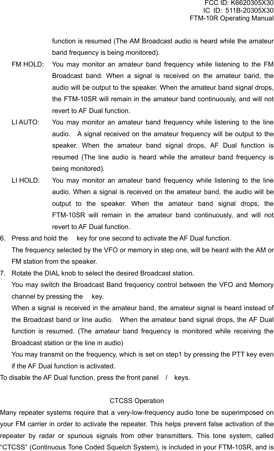
![FCC ID: K6620305X30 IC ID: 511B-20305X30 FTM-10R Operating Manual alternately, and a “LOW BATT” icon will appear in the display. When the BH-1’s battery voltage becomes low, charge the BH-1’s battery as soon as possible by the CAB-1 Bluetooth® Head Set Charger Sleeve. You may reduce the BH-1’s battery consumption via the Menu Item “F7 BLU SAVE”. See page 93 for detail. The BH-1’s approximate battery life is as follows: Operating Band Battery Life (Approx.) AM/FM Broadcast, External Audio Input 3 hours Amateur Band 1:1:8 (TX:RX:Standby) Save ON: 10 hours Save OFF: 3 hours AF Dual Function The AF Dual function allows you to monitor your desired amateur band frequency while listening to an AM broadcast station. You may monitor the FM broadcast station or external line input instead of an AM broadcast station by changing Menu Item “F2 AF DUAL” (The factory default is AM broadcast receiving). 1. Set the FTM-10SR to the desired amateur band frequency while in VFO or Memory channel. 2. Press and hold the [VOL/SEL] key for one second to activate the Menu Mode. 3. Rotate the DIAL knob to select Menu Item “F2 AF DUAL”. 4. Press the key to enable selection of this Menu item. 5. Rotate the DIAL knob to select the band and mode you want to listen to: AM AUTO: You may monitor an amateur band frequency while listening to an AM Broadcast station. A signal received on the amateur frequency will be output to the speaker. When the amateur band signal drops, AF Dual function is resumed (The AM Broadcast audio is heard while the amateur band frequency is being monitored). AM HOLD: You may monitor an amateur band frequency while listening to the AM Broadcast band. When a signal is received on the amateur band the audio will be output to the speaker. When the amateur band signal drops the FTM-10SR remains in the amateur band continuously, and will not revert to AF Dual function. FM AUTO: You may monitor an amateur band frequency while listening to an FM Broadcast station. A signal received on the amateur frequency will be output to the speaker. When the amateur band signal drops, AF Dual Vertex Standard Co., Ltd. 51](https://usermanual.wiki/Yaesu-Musen/20305X30/User-Guide-805828-Page-51.png)
![FCC ID: K6620305X30 IC ID: 511B-20305X30 FTM-10R Operating Manual very easy to activate. CTCSS setup involves setting the Tone Mode and then setting of the Tone Frequency. These actions are set up using Menu Items “F40 SQL TYPE” and “F39 SQL TSQF”. 1. Press and hold the [VOL/SEL] key for one second to activate the Menu Mode. 2. Rotate the DIAL knob to select Menu Item “F40 SQL TYPE”. 3. Press the key to enable selection of this Menu Item. 4. Rotate the DIAL knob so that “TONE SQL” appears on the display. This means that the Tone Squelch system is active, which mutes your FTM-10SR’s receiver until it receives a call from another radio sending out a matching CTCSS tone. This can help keep your radio quiet until a specific call is received, which may be helpful while operating in congested areas. Note: 1) You may notice a “REV TONE” indication on the display while you rotate the DIAL knob in this step. This means that the Reverse Tone Squelch system is active, which mutes your FTM-10SR’s receiver (instead of opening the squelch) when it receives a call from the radio sending a matched CTCSS tone. The “T SQ” icon will blink on the display when the Reverse Tone Squelch system is activated. Note: 2) You may notice a “DCS” indication on the display while you rotate the DIAL knob still more. We’ll discuss the Digital Code Squelch system shortly. 5. When you have made your selection of the CTCSS tone mode, press the key momentarily, then rotate the DIAL knob three clicks counter-clockwise to select Menu Item “F39 SQL TSQF”. This Menu selection allows setting of the CTCSS tone frequency to be used. 6. Press the key to enable adjustment of the CTCSS frequency. 7. Rotate the DIAL knob until the display indicates the Tone Frequency you need to use. 8. Press the [VOL/SEL] key to save the new setting and exit to normal operation. Note: Your repeater may or may not re-transmit a CTCSS tone. Some systems just use CTCSS to control access to the repeater, but don’t pass it along when transmitting. If the S-Meter deflects, but the FTM-10SR is not passing audio, repeat steps “1” through “4” above, but rotate the DIAL knob so that “TONE” appears. This will allow you to hear all traffic on the channel being received. DCS Operation Another form of tone access control is Digital Code Squelch, or DCS. It is a newer, more advanced tone system that generally provides more immunity from false paging than does CTCSS. The DCS Encoder/Decoder is built into your FTM-10SR, and operation is very Vertex Standard Co., Ltd. 53](https://usermanual.wiki/Yaesu-Musen/20305X30/User-Guide-805828-Page-53.png)
![FCC ID: K6620305X30 IC ID: 511B-20305X30 FTM-10R Operating Manual similar to that just described for CTCSS. Your repeater system may be configured for DCS. If not, it is frequently quite useful in Simplex operation if your friend(s) use transceivers equipped with this advanced feature. Note: Just as in CTCSS operation, DCS requires that you set the Tone Mode to DCS and that you select a DCS Code. 1. Press and hold the [VOL/SEL] key for one second to activate the Menu mode. 2. Rotate the DIAL knob to select Menu Item “F40 SQL TYPE”. 3. Press the key to enable selection of this Menu Item. 4. Rotate the DIAL knob so that “DCS” appears on the display. This means that the DCS Encoder/Decoder is active, which mutes your FTM-10SR’s receiver until it receives a call from another radio sending out a matching DCS tone. 5. When you have made your selection of the DCS mode, press the key momentarily, then rotate the DIAL knob two clicks counter-clockwise to select Menu Item “F36 SQL DCS”. This Menu selection allows setting of the DCS code to be used. 6. Press the key to enable adjustment of the DCS code. 7. Rotate the DIAL knob until the display indicates the DCS code (three-digits number) you need to be using. 8. Press the [VOL/SEL] key to save the new setting and exit to normal operation. Note: Remember that DCS is an Encode/Decode system, so your receiver will remain muted until a matching DCS code is received on an incoming transmission. Switch the DCS off when you’re just tuning around the band! EPCS (Enhanced Paging & Code Squelch) Operation The FTM-10SR includes an Enhanced CTCSS tone encoder/decoder and a dedicated microprocessor providing paging and selective calling features. This allows you to place a call to a specific station (Paging), and to receive calls of your choice directed only to you (Code Squelch). The paging and code squelch systems use two pairs of (alternately switched) CTCSS tones, which are stored in the pager memories. Basically, your receiver remains silent until it receives the CTCSS tone pair that matches those stored in the Receiving Pager Memory. The squelch then opens so the caller is heard, and the paging ringer immediately sounds, if activated. When you close the PTT key to transmit, the CTCSS tone pair that is stored in the Transmitting Pager Memory will be transmitted automatically. On the paged radio, the squelch will close automatically after the incoming page ends. Storing the CTCSS Tone Pairs for EPCS Operation Vertex Standard Co., Ltd. 54](https://usermanual.wiki/Yaesu-Musen/20305X30/User-Guide-805828-Page-54.png)
![FCC ID: K6620305X30 IC ID: 511B-20305X30 FTM-10R Operating Manual 1. Press and hold the [VOL/SEL] key for one second to activate the Menu mode. 2. Rotate the DIAL knob to select Menu Item “F21 PAGER”. 3. Press the key to enable selection of this Menu Item. 4. Press and hold the key for one second to display the current Receiving CTCSS Tone Pair. 5. Rotate the DIAL knob to set the CTCSS Tone number that corresponds to the first tone of the Receiving CTCSS Tone Pair. 6. Press the key, then rotate the DIAL knob to set the CTCSS Tone number that corresponds to the second tone of the Receiving CTCSS Tone Pair. 7. Repeat step 6 for setting the Transmitting CTCSS Tone Pair. 8. If you make a mistake, press the key to move the cursor back one space, then re-select the correct number. 9. When you have made your selection of both Receiving and Transmitting CTCSS tone pairs, press the [VOL/SEL] key to save the new setting and exit to normal operation. Note: The FTM-10SR does not recognize the order of the 1st tone and the 2nd tone. In other words, for example, the FTM-10SR considers both CTCSS pairs “10, 35” and “35, 10” to be identical. Activating the EPCS 1. Press and hold the [VOL/SEL] key for one second to activate the Menu mode. 2. Rotate the DIAL knob to select Menu Item “F21 PAGER”. 3. Press the key to enable selection of this Menu Item. 4. Rotate the DIAL knob to change the display to “ON”. 5. Press the [VOL/SEL] key momentarily to save the new setting and exit to normal operation. To disable the EPCS, just repeat the above procedure, rotating the DIAL knob to select “OFF” in step 4 above. When the EPCS is activated, the “T” icon will blink during operation. Internet Connection Feature (WIRESTM) The FTM-10SR can be used to access a “node” (repeater or base station), which is tied into the Vertex Standard WiRESTM (Wide-Coverage Internet Repeater Enhancement System) network. Details may be found at the WiRES-II Web site: http://www.vxstd.com/en/wiresinfo-en/. This feature may also be used to access other systems, as described below. Vertex Standard Co., Ltd. 55](https://usermanual.wiki/Yaesu-Musen/20305X30/User-Guide-805828-Page-55.png)
![FCC ID: K6620305X30 IC ID: 511B-20305X30 FTM-10R Operating Manual SRG (“Sister Radio Group”) mode 1. Press and hold the [VOL/SEL] key for one second to activate the Menu mode. 2. Rotate the DIAL knob to select Menu Item “F48 WIRES”. 3. Press the key to enable selection of this Menu Item. 4. Rotate the DIAL knob until “CODE” appears on the display. This activates WiRESTM in SRG mode. The “INTERNET” icon will appear on the display. 5. Press and hold the key for one second. Then rotate the DIAL knob while to select the access number (“CODE 0” ~ “CODE 9”, “CODE A”, “CODE B”, “CODE C”, “CODE D”, “CODE E (*)”, “CODE F (#))” corresponding to the WiRESTM node to which you wish to establish the WiRESTM connection. (ask the node or repeater owner/operator if you don’t know the access number in the network). 6. Press the [VOL/SEL] key to save the new setting and exit to normal operation. 7. With the Internet Connection feature activated (as in step 4 above), the FTM-10SR will generate a brief (0.1 second) DTMF tone according to your selection in step 5. This DTMF tone is sent at the beginning of every transmission to establish or maintain the link to the local WiRESTM node operating in the SRG mode. 8. To return to the FRG mode, repeat steps 1 - 4 above, selecting “MEM” in step 4, then press the [VOL/SEL] key to save the new setting and exit to normal operation. 9. To disable the Internet Connection feature, just repeat the above procedure, rotating the DIAL knob to select “OFF” in step 4 above, then press the [VOL/SEL] key to save the new setting and exit to normal operation (the “INTERNET” icon will disappear from the display). Note: If other users report that you always have a DTMF “beep” at the beginning of each transmission, and you are not operating in conjunction with Internet access, disable this function via step (4) above. FRG (“Friendly Radio Group”) mode You may access other Internet Link Systems (including WiRESTM in the “FRG” mode) that use a DTMF string for access. Programming the FRG code Load the DTMF tones that you wish to use for Internet-link access into a DTMF memory register. For purposes of this example, we will use “# (F)1101D” as the access code (the “#” key is denoted by the letter “F”). 1. Press and hold the [VOL/SEL] key for one second to activate the Menu mode. Vertex Standard Co., Ltd. 56](https://usermanual.wiki/Yaesu-Musen/20305X30/User-Guide-805828-Page-56.png)
![FCC ID: K6620305X30 IC ID: 511B-20305X30 FTM-10R Operating Manual 2. Rotate the DIAL knob to select Menu Item “F13 DTMF”. 3. Press the key to enable selection of this Menu Item. 4. Rotate the DIAL knob to select the DTMF memory register (D1 ~ D9) into which you wish to store the access code. 5. Press and hold the key for one second. The first digit will blink. 6. Rotate the DIAL knob to select “F” (representing DTMF “#” the first digit of the DTMF string). “E” representing DTMF “*” and “F” representing DTMF “#”. 7. Press the key momentarily to accept the first digit and move to the second digit of the DTMF string. 8. Repeat the previous steps until you have completed the access code (“# (F)1101D”). 9. If you make a mistake, press the key to backspace the cursor, then re-enter the correct number. 10. Press and hold the key for one second to save the new setting. 11. Repeat steps 1 through 10 to store other access codes, if so desired. 12. Press the [VOL/SEL] key to save the setting and exit to normal operation. To accessing an FRG Node 1. Press and hold the [VOL/SEL] key for one second to activate the Menu mode. 2. Rotate the DIAL knob to select Menu Item “F48 WIRES”. 3. Press the key to enable selection of this Menu Item. 4. Rotate the DIAL knob until “MEM” appears on the display. This activates WiRESTM in FRG mode. The “INTERNET” icon will appear on the display. 5. Press and hold the key for one second, then rotate the DIAL knob to select the Internet Memory register number (D1 ~ D9) corresponding to the Internet link repeater to which you wish to establish an Internet link. 6. Press the [VOL/SEL] key to save the new setting and exit to normal operation. 7. Once the Internet Connection feature is activated per step 4 above, you may now press the key, while you are transmitting, to send out the selected DTMF string (to establish the link to the desired Internet-link node). 8. To disable the Internet Connection feature, repeat steps 1 - 4 above, selecting “OFF” in step 4, then press the [VOL/SEL] key to save the new setting and exit to normal operation (the “INTERNET” icon will disappear from the display). DTMF Autodialer Nine Autodialer memories are available on the FTM-10SR. These DTMF Autodialer Vertex Standard Co., Ltd. 57](https://usermanual.wiki/Yaesu-Musen/20305X30/User-Guide-805828-Page-57.png)
![FCC ID: K6620305X30 IC ID: 511B-20305X30 FTM-10R Operating Manual memories can store up to 16 digits of a telephone number for repeater autopatch or other use. To load the DTMF Autodialer memories: 1. Press and hold the [VOL/SEL] key for one second to activate the Menu mode. 2. Rotate the DIAL knob to select Menu Item “F13 DTMF”. 3. Press the key to enable selection of this Menu item. 4. Rotate the DIAL knob to select the DTMF AutoDial memory channel number into which you wish to store a telephone number (“D1” to “D9”). The previously stored telephone number is displayed on the LCD. 5. Press and hold the key for one second. Press the PTT key to clear any previously stored telephone number, if desired. 6. Rotate the DIAL knob to select the first digit of the telephone number you wish to store. Then press the key momentarily to save the first digit of the telephone number and move on to the next digit. “E” representing DTMF “*” and “F” representing DTMF “#”. 7. Repeat previous step for each digit in the telephone number. If you make a mistake, press the key to move the cursor back to the previous digit, then re-enter the correct number. Press the PTT key to delete all data after the cursor that may have been previously stored erroneously. 8. When entries of all digits are complete, press and hold the key for one second. 9. If you wish to store another DTMF string, repeat steps 4 through 8 above. 10. Press the [VOL/SEL] key momentarily to save the new setting and exit to normal operation. To transmit the memorized telephone number: 1. Press the PTT key, then press and hold the key while transmitting. The “DT MEM” indication will appear in the display for a moment (thus enabling the DTMF AutoDial), and “DTMF” icon will appear in the display. 2. Press the key while maintaining a transmission. 3. Rotate the DIAL knob to select the DTMF AutoDial memory channel number you wish to transmit (“D1” to “D9”) while maintaining a transmission. 4. Press the key again while maintaining a transmission. The telephone number is transmitted. If you use the optional DTMF hand Microphone “MH-68A6J” you may send the telephone number using the following steps: Vertex Standard Co., Ltd. 58](https://usermanual.wiki/Yaesu-Musen/20305X30/User-Guide-805828-Page-58.png)
![FCC ID: K6620305X30 IC ID: 511B-20305X30 FTM-10R Operating Manual 1. First press the PTT key, then press the microphone’s numeric keys ([1] through [9]) corresponding to the DTMF memory string you wish to send. 2. Once the string begins, you may release the PTT key, as the transmitter will be held “on the air” until the DTMF string is completed. The transmitter will hold for 1.5 seconds after completion of the DTMF Memory string. When the transmission is completed, press and hold the key while transmitting to eliminate the “DTMF” icon. Repeater Operation The FTM-10SR includes a host of convenient features that makes operation on amateur repeaters both efficient and enjoyable. The FTM-10SR offers three methods of setting up split-frequency operation on repeaters: Manual selection of preset repeater shifts (Standard Repeater Shift); Automatic Repeater Shift (ARS), providing automatic activation of repeater shifts while operating within designated repeater frequency subbands. Independently stored transmit and receive frequencies (typically not corresponding to established repeater frequency shifts). Standard Repeater Shift To activate the standard shift manually, you may use the Menu mode: 1. Press and hold the [VOL/SEL] key for one second to activate the Menu mode. 2. Rotate the DIAL knob to select Menu Item “F25 RPT MODE”. 3. Press the key to enable selection of this Menu Item. 4. Rotate the DIAL knob to select desired shift direction (RPTR–, RPTR+, or RPTR OFF). 5. Press the [VOL/SEL] key momentarily to save the new setting and exit to normal operation. Your FTM-10SR has been configured, at the factory, for the repeater offset customary in your country. For the 144 MHz band offset will be 600 kHz; on the 430 MHz band, the offset may be 1.6 MHz, 7.6 MHz. You can change the offset using the following procedure, if needed for vacation travel or other purposes: 1. Press and hold the [VOL/SEL] key for one second to activate the Menu mode. 2. Rotate the DIAL knob to select Menu Item “F26 RPT SFT”. 3. Press the key to enable selection of this Menu Item. 4. Rotate the DIAL knob to set the desired offset. Note that the resolution of the “Standard” repeater shift is to the nearest 50 kHz multiple. Vertex Standard Co., Ltd. 59](https://usermanual.wiki/Yaesu-Musen/20305X30/User-Guide-805828-Page-59.png)
![FCC ID: K6620305X30 IC ID: 511B-20305X30 FTM-10R Operating Manual 5. Press the [VOL/SEL] key to save the new setting and exit to normal operation. Note: Do not use this procedure for programming of an “odd split” type repeater pair! The process for programming odd splits is shown on page 42. Automatic Repeater Shift The ARS (Automatic Repeater Shift) feature in this transceiver allows easy and convenient repeater operation by automatically activating the repeater shift function whenever you tune to a frequency in a standard repeater sub band. The ARS function is preset at the factory to conform to the standards for the country to which it is exported. The ARS function is enabled at the factory. To disable ARS: 1. Press and hold the [VOL/SEL] key for one second to activate the Menu mode. 2. Rotate the DIAL knob to select Menu Item “F24 RPT ARS”. 3. Press the key to enable selection of this Menu Item. 4. Rotate the DIAL knob to change the display to “OFF”. 5. Press the [VOL/SEL] key to save the new setting and exit to normal operation. To enable the ARS function again, just repeat the above procedure, rotating the DIAL knob to select “ON” in step 4 above. Band Expansion The FTM-10SR can receive the following frequency bands via the Menu Item. AIR: 108 - 137 MHz and 300 - 336 MHz GR1: 174 - 222 MHz and 470 - 800 MHz GR2: 336 - 420 MHz and 800 - 999.9875 MHz (cellular blocked) 1. Press and hold the [VOL/SEL] key for one second to activate the Menu mode. 2. Rotate the DIAL knob to select Menu Item “F27 RX EXP”. 3. Press the key to enable selection of this Menu Item. 4. Rotate the DIAL knob to change the setting to “EXPAND”. 5. Press the [VOL/SEL] key to save your new setting and resume normal operation. When the band is expanded, you can see the “AIR”, “GR1”, and “GR2” additional frequency bands between the “WX Band” and “Audio Line”. Weather Broadcast Channel Operation The VHF Weather Broadcast Station Memory Channel Bank has been pre-programmed at the factory, for quick selection of NOAA weather information stations. 1. Press the front panel / key to recall the Weather Broadcast Station Memory Bank (“WX” notation will appear at the upper left corner in the display for a moment). Vertex Standard Co., Ltd. 60](https://usermanual.wiki/Yaesu-Musen/20305X30/User-Guide-805828-Page-60.png)
![FCC ID: K6620305X30 IC ID: 511B-20305X30 FTM-10R Operating Manual 2. Rotate the DIAL knob to select the desired Weather Broadcast channel. 3. If you wish to scan this bank to search for louder stations, just press the PTT key. When the scanner pauses on a station, press the PTT key once to halt the can, or press it twice to restart the scan. 4. To exit from the Weather Broadcast Station Memory mode, press the front panel / keys to select the desired operating band. CH Frequency CH Frequency 1 162.550 MHz 6 162.500 MHz 2 162.400 MHz 7 162.525 MHz 3 162.475 MHz 8 161.650 MHz 4 162.425 MHz 9 161.775 MHz 5 162.450 MHz 10 163.275 MHz Severe Weather Alert In the event of extreme weather disturbances, such as storms and hurricanes, the NOAA (National Oceanic and Atmospheric Administration) sends a weather alert accompanied by a 1050 Hz tone and subsequent weather report on one of the NOAA weather channels. Miscellaneous Setting Channel Step Selection Tuning steps are factory preset to default increments which are appropriate for the country to which this radio is exported. You may have a reason to use a different step size, however, and here is the procedure for changing the channel steps: 1. Press and hold the [VOL/SEL] key for one second to activate the Menu mode. 2. Rotate the DIAL knob to select Menu Item “F41 STEP”. 3. Press the key to enable selection of this Menu Item. 4. Rotate the DIAL knob to select the desired step size: 5.00, 6.25, 8.33, 10.00, 12.50, 15.00, 20.00, 25.00, 50.00, 100.00, 200.00 kHz or AUTO. 5. Press the [VOL/SEL] key to save the new setting and exit to normal operation. Note: 1) AM BC band only selects 9 kHz or 10 kHz. Note: 2) FM BC band only selects 50 kHz, 100 kHz, or 200 kHz. Note: 3) Steps of 5 kHz, 6.25 kHz, 8.33kHz, and 9 kHz are not available above 470 MHz. Changing the Operating Mode The FTM-10SR provides for automatic mode changing when the radio is tuned to different Vertex Standard Co., Ltd. 61](https://usermanual.wiki/Yaesu-Musen/20305X30/User-Guide-805828-Page-61.png)
![FCC ID: K6620305X30 IC ID: 511B-20305X30 FTM-10R Operating Manual operating frequencies. However, should an unusual operating situation arise in which you need to change between the available operating modes (FM, FM-Narrow, FM-Wide, and AM), here is the procedure for doing so: 1. Press and hold the [VOL/SEL] key for one second to activate the Menu mode. 2. Rotate the DIAL knob to select Menu Item “F29 RX M MOD”. 3. Press the key to enable selection of the operating mode. The current operating mode appears on the LCD. 4. Rotate the DIAL knob to select the desired operating mode. AUTO: Automatic mode setting per default values for the selected frequency range. WIDE FM: Frequency Modulation for receiving an FM Broadcast Station. FM: Frequency Modulation for receiving an Amateur Radio Station and most VHF/UHF Communication. NARR FM: Frequency Modulation for receiving some Amateur Radio Stations and VHF/UHF Communication. AM: Amplitude Modulation for receiving a AM Radio Station and Air Band Communication. Press the [VOL/SEL] key to save the new setting and resume normal operation. PTT key function You can select the PTT key function desired. 1. Press and hold the [VOL/SEL] key for one second to activate the Menu mode. 2. Rotate the DIAL knob to select Menu Item “F23 PTT MODE”. 3. Press the key to enable selection of the PTT key function. The current PTT key function appears on the LCD. 4. Rotate the DIAL knob to select the desired PTT key function. TOGGLE: While pressing the PTT key, the audio is output from the speaker (factory default). MOMENT: Once the PTT key is pressed the audio is output from the speaker, and the PTT key is pressed once again, the audio output is turned off. 5. Press the [VOL/SEL] key to save the new setting and resume normal operation. Key Beeper A key beeper provides useful audible feedback whenever a key is pressed. Follow this procedure to turn the beeper on or off: 1. Press and hold the [VOL/SEL] key for one second to activate the Menu mode. Vertex Standard Co., Ltd. 62](https://usermanual.wiki/Yaesu-Musen/20305X30/User-Guide-805828-Page-62.png)
![FCC ID: K6620305X30 IC ID: 511B-20305X30 FTM-10R Operating Manual 2. Rotate the DIAL knob to select Menu Item “F6 BEEP”. 3. Press the key to enable selection of this Menu Item. 4. Rotate the DIAL knob to change the setting to “OFF”. 5. Press the [VOL/SEL] key to save the new setting and exit to normal operation. 6. To turn the beep back on again, select “KEY” or “KEY+SC (factory default)” in step 4 above. KEY: The beeper sounds when you press the key. KEY+SC: The beeper sounds when you press the key, or when the scanner stops. Smart Key Select You may assign/exclude the functions which recall with the top panels’ / key. 1. Press and hold the [VOL/SEL] key for one second to activate the Menu mode. 2. Rotate the DIAL knob to select Menu Item “F15 FKEY SEL”. 3. Press the key to enable selection of this Menu Item. 4. Rotate the DIAL knob to select the function you wish to assign or exclude. 5. Press and hold the key for one second to toggle the function on (assign) and off (exclude). 6. Press the [VOL/SEL] key to save the new setting and exit to normal operation. Repeater Shift Direction You may select the Repeater Shift Direction. 1. Press and hold the [VOL/SEL] key for one second to activate the Menu mode. 2. Rotate the DIAL knob to select Menu Item “F25 RPT MODE”. 3. Press the key to enable selection of this Menu Item. 4. Rotate the DIAL knob to select desired shift direction (RPTR-, RPTR+, or RPTR OFF). 5. Press the [VOL/SEL] key momentarily to save the new setting and exit to normal operation. The repeater offset is fixed to 600 kHz on the 144 MHz band and 5 MHz on the 430 MHz band from the factory. You can change the offset via the Menu mode “F26 RPT SFT”. Repeater Shift Offset 1. Press and hold the [VOL/SEL] key for one second to activate the Menu mode. 2. Rotate the DIAL knob to select Menu Item “F26 RPT SFT”. 3. Press the key to enable selection of this Menu Item. 4. Rotate the DIAL knob to select desired offset. 5. Available selections are 0.00 - 99.95 MHz (50 kHz increments). Vertex Standard Co., Ltd. 63](https://usermanual.wiki/Yaesu-Musen/20305X30/User-Guide-805828-Page-63.png)
![FCC ID: K6620305X30 IC ID: 511B-20305X30 FTM-10R Operating Manual 6. Press the [VOL/SEL] key momentarily to save the new setting and exit to normal operation. Automatic Repeater Shift The ARS (Automatic Repeater Shift) feature in this transceiver allows easy and convenient repeater operation by automatically activating the repeater shift function whenever you tune to a frequency in a standard repeater sub band. The ARS function is preset at the factory to conform to the standards for the country to which it is exported. The ARS function is enabled at the factory. To disable ARS: 1. Press and hold the [VOL/SEL] key for one second to activate the Menu mode. 2. Rotate the DIAL knob to select Menu Item “F24 RPT ARS”. 3. Press the key to enable selection of this Menu Item. 4. Rotate the DIAL knob to change the display to “OFF”. 5. Press the [VOL/SEL] key to save the new setting and exit to normal operation. To enable the ARS function again, just repeat the above procedure, rotating the DIAL knob to select “ON” in step 4 above. Programming the Key Assignments In the factory default, the optional MH-68A6J/MH-68B6J Microphone’s [PGM] key functions have been assigned to the “WX CH”. This may be changed by the user if you wish to assign quick access to another function. To change the assignments for the MH-68A6J/MH-68B6J Microphone’s [PGM] key: 1. Press and hold the [VOL/SEL] key for one second to activate the Menu mode. 2. Rotate the DIAL knob to select Menu Item “F20 MIC PRGM”. 3. Press the key to enable selection of this Menu item. 4. Rotate the DIAL knob to select the function you wish to assign to the [PGM] key. The available choices are: MONI: Disable the noise and tone squelch systems. T CALL: Activates 1750 Hz Tone Burst SSCH: Engages the Smart Search operation. ARTS: Engages the ARTSTM operation. TAG: Switches the display between indication of the frequency or the channel’s Alpha/Numeric label while receiving on the memory channel. MHz: Allows 1-MHz tuning steps while receiving in VFO mode. Vertex Standard Co., Ltd. 64](https://usermanual.wiki/Yaesu-Musen/20305X30/User-Guide-805828-Page-64.png)
![FCC ID: K6620305X30 IC ID: 511B-20305X30 FTM-10R Operating Manual SCAN: Engages the Scan operation. CLUB: Recall the CLUB channel. WX: Switches operation to the Weather Channel bank. SQLLVL: Selects the Squelch Threshold Level TX LOW: Selects the Transmitter Power Level. RPTR: Sets the Repeater Shift Direction. SQL TYP: Selects the CTCSS/DSC Operation. REV: Reverses the Transmit and receive frequency during split-frequency operation. TSQLF: Selects the CTCSS frequency. DCODE: Selects the DCS code. 5. Press the [VOL/SEL] key to save the new setting and exit to normal operation. Scanning Band By default, the FTM-10SR considers the 144 MHz Amateur Band and 430 MHz Amateur Band to be independent bands while the scanner is activated. You may change scanner operation so that both the 144 MHz Amateur Band and the 430 MHz Amateur Band are scanned as one band. 1. Press and hold the [VOL/SEL] key for one second to activate the Menu mode. 2. Rotate the DIAL knob to select Menu Item “F30 SCN CVRG”. 3. Press the key to enable selection of this Menu Item. 4. Rotate the DIAL knob to select the desire mode. IN BAND: The FTM-10SR considers the 144 MHz Amateur Band and 430 MHz Amateur Band to be an independent band and scans these when the scan mode is engaged. Activate the scanner on the 144 MHz Amateur Band only (or 430 MHz Amateur Band only). HAM BAND: The FTM-10SR considers the 144 MHz Amateur Band and 430 MHz Amateur Band to be one band and scans it when the scan mode is engaged. Activate the scanner across the 144 MHz Amateur Band and 430 MHz Amateur Band. 5. Press the [VOL/SEL] key to save the new setting and exit to normal operation. Scan-Resume Mode Three scan-resume modes are available on the FTM-10SR: BUSY: In this mode, the scanner will remain halted for as long as there is carrier present on the channel. After the carrier drops at the end of the other Vertex Standard Co., Ltd. 65](https://usermanual.wiki/Yaesu-Musen/20305X30/User-Guide-805828-Page-65.png)
![FCC ID: K6620305X30 IC ID: 511B-20305X30 FTM-10R Operating Manual station's transmission, scanning will resume. HOLD: In this mode, the scanner will halt on a signal it encounters. It will not restart automatically; you must manually re-initiate scanning if you wish to resume. TIME 3S/5S/10S: In these modes, the scanner will halt for the selected resume time, after which scanning will resume (whether or not the other station is still transmitting). The default scan-stop mode is “BUSY”. To change the scan-resume mode, use the following procedure: 1. Press and hold the [VOL/SEL] key for one second to activate the Menu mode. 2. Rotate the DIAL knob to select Menu Item “F32 SCN MODE”. 3. Press the key to enable selection of this Menu Item. 4. Rotate the DIAL knob to set the desired scan-resume mode. 5. Press the [VOL/SEL] key to save the new setting and exit to normal operation. Scan Direction By default, the VFO frequency will jump to the low band edge of the current band when the VFO frequency reaches the high band edge. You may change the scanner operation so that the VFO frequency will change to downward scanning when the VFO frequency reaches the high band edge. 1. Press and hold the [VOL/SEL] key for one second to activate the Menu mode. 2. Rotate the DIAL knob to select Menu Item “F31 SCN DRCT”. 3. Press the key to enable selection of this Menu Item. 4. Rotate the DIAL knob to set the desired scan mode. NORMAL: When the VFO frequency reaches the high band edge of the current band, the VFO frequency will jump to the low band edge of the current band (or vice versa). RETURN: When the VFO frequency reaches the high band edge of the current band while scanning upward, the scanner will reverse direction and scan downwards. (or vice versa). 5. Press the [VOL/SEL] key to save the new setting and exit to normal operation. Scan Start Direction By default, the scanner initiates scanning upward when activates the scanner by pressing the top panels’ [F] key. You may change the scan start direction to downward scanning. 1. Press and hold the [VOL/SEL] key for one second to activate the Menu mode. Vertex Standard Co., Ltd. 66](https://usermanual.wiki/Yaesu-Musen/20305X30/User-Guide-805828-Page-66.png)
![FCC ID: K6620305X30 IC ID: 511B-20305X30 FTM-10R Operating Manual 2. Rotate the DIAL knob to select Menu Item “F33 SCN STRT”. 3. Press the key to enable selection of this Menu Item. 4. Rotate the DIAL knob to set the desired direction. UP START: the scanner initiates scanning upward. DWN.TRART: the scanner initiates scanning downward. Press the [VOL/SEL] key to save the new setting and exit to normal operation. Split Tone Operation The FTM-10SR can be operated in a “Split Tone” configuration, to enable operation on repeaters using a mix of both CTCSS and DCS control. 1. Press and hold the [VOL/SEL] key for one second to activate the Menu mode. 2. Rotate the DIAL knob to select Menu Item “F37 SQL.EXP”. 3. Press the key to enable selection of this Menu item. 4. Rotate the DIAL knob to set this Menu item to “ON” (to enable the Split Tone feature) 5. Press the [VOL/SEL] key momentarily to save the new setting and exit to normal operation. When the Split Tone feature is activated, you can see the following additional parameters following the “DCS” parameter (while selecting the tone mode via Menu item “F40 SQL TYPE”): DCS ENC: DCS Encode only (the “DCS” icon will blink during operation). TONE DCS: Encodes a CTCSS Tone and Decodes a DCS code (the “T” icon will blink and the “DCS” icon will appear during operation). DCS TSQL: Encodes a DCS code and Decodes a CTCSS Tone (the “TSQ” icon will appear and the “DCS” icon will blink during operation) CTCSS/DCS/EPCS Bell Operation During CTCSS Decode, DCS, or EPCS operation, you may set up the FTM-10SR so that a ringing “bell” sound alerts you when a call is coming in. 1. Press and hold the [VOL/SEL] key for one second to activate the Menu mode. 2. Rotate the DIAL knob to select Menu Item “F35 SQL BELL”. 3. Press the key to enable selection of this Menu Item. 4. Rotate the DIAL knob to set the desired number of rings of the Bell. The available choices are 1, 3, 5, or 8 rings, CONT (continuous ringing), or OFF. 5. Press the [VOL/SEL] key momentarily to save the new setting and exit to normal operation. When you are called by a station whose transceiver is sending a CTCSS tone, DCS code, or Vertex Standard Co., Ltd. 67](https://usermanual.wiki/Yaesu-Musen/20305X30/User-Guide-805828-Page-67.png)
![FCC ID: K6620305X30 IC ID: 511B-20305X30 FTM-10R Operating Manual CTCSS code pair which matches that set into your Decoder, the Bell will ring in accordance with this programming. Battery Voltage Display You can display the vehicle's battery voltage on the display at any time. 1. Press and hold the [VOL/SEL] key for one second to activate the Menu mode. 2. Rotate the DIAL knob to select Menu Item “F11 DC VOLT”. 3. Press the key to display the vehicle’s battery voltage on the display. 4. Press the [VOL/SEL] key to exit Battery Voltage mode and return to normal operation. Temperature Display You can show the temperature inside the front panel on the display. 1. Press the [VOL/SEL] key repeatedly to display the Clock, Stop Watch Timer, or Thermometer. The display returns to the frequency display automatically if you leave an interval of three seconds without entering the next operation. Please enter the next step within the 3 second interval. 2. Rotate the DIAL knob to display the temperature (TMP XX °C) The display automatically returns to the frequency display in approximately three seconds. You may change the status that the DIAL knob does not return automatically to the Frequency. See the explanation of the Menu Item “F5 AF-VFO”. Clock Format You may select the Clock Format via the Menu mode. Available selections are “HH:MM:SS”, “HH:MM”, and “MM:SS”. 1. Press the [VOL/SEL] key repeatedly to display the Clock, Stop Watch Timer, or Thermometer. The display returns to the frequency display automatically if you leave an interval of approximately three seconds before the next operation. Please operate the next step within the 3 second interval. 2. Press and hold the [VOL/SEL] key for one second. 3. Rotate the DIAL knob to select the Menu Item “T3 T FORMAT”. 4. Press the key momentarily. Then rotate the DIAL knob to select the desired Clock Format. 5. Press the [VOL/SEL] key to save the new setting and exit to normal operation. Vertex Standard Co., Ltd. 68](https://usermanual.wiki/Yaesu-Musen/20305X30/User-Guide-805828-Page-68.png)
![FCC ID: K6620305X30 IC ID: 511B-20305X30 FTM-10R Operating Manual Time System You may select the Time System between “12H” and “24H” via the Menu mode. 1. Press the [VOL/SEL] key repeatedly to display the Clock, Stop Watch Timer, or Thermometer. The display returns to the frequency display automatically if you leave an interval of approximately three seconds before the next operation. Please operate the next step within the 3 second interval. 2. Press and hold the [VOL/SEL] key for one second. 3. Rotate the DIAL knob to select the Menu Item “T4 12H/24H”. 4. Press the key momentarily. Then rotate the DIAL knob to select the desired Time System. 5. Press the [VOL/SEL] key to save the new setting and exit to normal operation. Alarm Set You may set an alarm beep which will sound every “00” minutes via the Menu mode. 1. Press the [VOL/SEL] key repeatedly to display the Clock, Stop Watch Timer, or Thermometer. 2. Press and hold the [VOL/SEL] key for one second. 3. Rotate the DIAL knob to select the Menu Item “T2 CLOCK BP”. 4. Press the key momentarily. Then rotate the DIAL knob to change the setting to “ON”. 5. Press the [VOL/SEL] key to save the new setting and exit to normal operation. To turn the alarm off again, select “OFF” in step 4 above. Interval Beep The FTM-10SR’s Stop Watch Timer allows programming a timed interval when a beep will sound and the white LED will flash. 1. Press the [VOL/SEL] key repeatedly to recall the Clock/Timer mode. 2. Press and hold the [VOL/SEL] key for one second to activate the Clock/Timer Customization mode. 3. Rotate the DIAL knob to select Menu Item “T5 TMR BEEP”. 4. Press the key momentarily to enable selection of this Menu Item. 5. Rotate the DIAL knob to select the desired interval. Available selections are “5 MIN” through “60MIN” (5MIN increment) or “OFF”. 6. Now, press the [VOL/SEL] key to save the new setting and exit to Clock/Timer mode. To disable the interval timer, just repeat the above procedure, rotating the DIAL knob to Vertex Standard Co., Ltd. 69](https://usermanual.wiki/Yaesu-Musen/20305X30/User-Guide-805828-Page-69.png)
![FCC ID: K6620305X30 IC ID: 511B-20305X30 FTM-10R Operating Manual select “OFF” in step 5 above. Automatic Power-Off (APO) The “Automatic Power-Off” (APO) feature will turn the radio completely off after a user-defined period of PTT or key/button inactivity. If you do not press any front panel keys or buttons, rotate the DIAL knob, use the microphone’s keys and buttons, or transmit, and so long as the transceiver is not scanning or engaged in priority monitoring, the radio will shut itself off after the specified time period. The FTM-10SR can operate the Automatic Power-Off feature through the Clock/Timer function. The available selections for the time before power-off are 0.5 - 12.0 hours (0.5 hour increments), as well as APO Off. This feature is useful in minimizing battery drain in a mobile installation if you forget to turn the transceiver off when you leave your vehicle. To activate the APO feature: 1. Press the [VOL/SEL] key repeatedly to display the Clock, Stop Watch Timer, or Thermometer. 2. Press and hold the [VOL/SEL] key for one second. 3. Rotate the DIAL knob to select Menu Item “T8 APO”. 4. Press the key to enable selection of this Menu Item. 5. Rotate the DIAL knob to select desired time, after which the radio will automatically shut down. Available selections are 0.5 to 12.0 hours (0.5 hour increments), or Off. 6. Press the [VOL/SEL] key to save the new setting and exit to Clock/Timer mode. If there is no action by you within the time interval programmed, a ringer sounds 3 minutes before the APO shutdown time. Three minutes thereafter, the microprocessor will shut down the radio automatically. Audio Pitch Control The FTM-10SR includes a feature that lets you choose six special receiver audio responses to allow the most comfortable and effective reception in noisy environments. The effect is similar to that provided by a “Tone Control” in a stereo. 1. Press and hold the [VOL/SEL] key for one second to activate the Menu mode. 2. Rotate the DIAL knob to select Menu Item “F3 AF PITCH”. 3. Press the key to enable selection of this Menu Item. 4. Rotate the DIAL knob to select the desired receiver audio response. Available selections are LOW-3, LOW-2, LOW-1, NORMAL, HIGH-1, and HIGH-2. Vertex Standard Co., Ltd. 70](https://usermanual.wiki/Yaesu-Musen/20305X30/User-Guide-805828-Page-70.png)
![FCC ID: K6620305X30 IC ID: 511B-20305X30 FTM-10R Operating Manual 5. Press the [VOL/SEL] key to save the new setting and exit to normal operation. Volume Setting Alert feature The FTM-10SR provides the Volume Setting Alert feature. 1. Press and hold the [VOL/SEL] key for one second to activate the Menu mode. 2. Rotate the DIAL knob to select Menu Item “F4 AF PREST”. 3. Press the key to enable selection of this Menu item. 4. Rotate the DIAL knob to select the desired effect level. OV ALERT: Activates the Volume Setting Alert feature. A lamp at the left of the DIAL knob blinks orange when volume level is set to the ±3 steps of the preset level. LV ALERT: Activates the Volume Setting Alert feature. A lamp at the left of the DIAL knob blinks orange when volume level is set to the preset level minus 3 steps. HV ALERT: Activates the Volume Setting Alert feature. A lamp at the left of the DIAL knob blinks orange when volume level is set to the preset level plus 3 steps above. OFF: Disable the Volume Setting Alert feature. 5. Press and hold the key for one second, then rotate the DIAL knob to select the desired preset level. 6. Press the [VOL/SEL] key to save the new setting and exit to normal operation. Speaker Selection You may choose the speaker to be used. 1. Press and hold the [VOL/SEL] key for one second to activate the Menu mode. 2. Rotate the DIAL knob to select Menu Item “F34 SPEAKER”. 3. Press the key to enable selection of this Menu item. 4. Rotate the DIAL knob to select the desired effect level. REAR: Outputs the receiving audio from the “SP/LINE-IN” connector (located in the transceiver’s body). F+R: Outputs the receiving audio from both FRONT speaker (located in the front panel) and “SP/LINE-IN” connector. FRONT: Outputs the receiving audio from the FRONT (located in the front panel) speaker. OFF: Disable the FRONT speaker and “SP/LINE-IN” connector. 5. Press the [VOL/SEL] key to save the new setting and exit to normal operation. Vertex Standard Co., Ltd. 71](https://usermanual.wiki/Yaesu-Musen/20305X30/User-Guide-805828-Page-71.png)
![FCC ID: K6620305X30 IC ID: 511B-20305X30 FTM-10R Operating Manual If you use the external speaker, this Menu Item is set to “REAR” or “F+R”. Stereo/Monaural Selection You may enjoy the FM Broadcast and external audio input in stereo output. 1. Press and hold the [VOL/SEL] key for one second to activate the Menu mode. 2. Rotate the DIAL knob to select Menu Item “F42 STEREO”. 3. Press the key to enable selection of this Menu item. 4. Rotate the DIAL knob to select between “STEREO” and “MONO”. 5. Press the [VOL/SEL] key to save the new setting and exit to normal operation. When Stereo Audio Output is selected, an “STEREO” icon appears on the display. MIC Gain Setting At the factory, a microphone gain has been programmed that should be satisfactory for the internal microphone and optional MH-68A6J/ MH-68B6J. If you us an after-market microphone, you may wish to set a different Microphone Gain Level. 1. Press and hold the [VOL/SEL] key for one second to activate the Menu mode. 2. Rotate the DIAL knob to select Menu Item “F19 MIC GAIN”. 3. Press the key to enable selection of this Menu Item. 4. Rotate the DIAL knob to select the desired Microphone Gain Level. Available selections are MIN, LOW, NORMAL, HIGH, and MAX. 5. Press the [VOL/SEL] key to save the new setting and exit to normal operation. PTT Lock You may also lock out the PTT key when the LOCK mode is activated. 1. Press and hold the [VOL/SEL] key for one second to activate the Menu mode. 2. Rotate the DIAL knob to select Menu Item “F22 PTT LOCK”. 3. Press the key to enable selection of this Menu Item. 4. Rotate the DIAL knob to select “ON” (Lock) or “OFF” (unlock). Press the [VOL/SEL] key to save the new setting and exit to normal operation. Menu (“Set”) Mode The FTM-10SR Menu Mode, already described in parts of many previous chapters, is easy to activate and set. It may be used for configuration of a wide variety of transceiver parameters, some of which have not been detailed previously. Use the following procedure to activate the Menu mode: Vertex Standard Co., Ltd. 72](https://usermanual.wiki/Yaesu-Musen/20305X30/User-Guide-805828-Page-72.png)
![FCC ID: K6620305X30 IC ID: 511B-20305X30 FTM-10R Operating Manual 1. Press and hold the [VOL/SEL] key for one second to enter the Menu mode. 2. Rotate the DIAL knob to select the Menu Item to be adjusted. 3. Press the key momentarily to enable adjustment of the Menu Item. 4. Rotate the DIAL knob to adjust or select the parameter to be changed on the Menu Item selected in the above step. 5. After completing your selection and adjustment, press the [VOL/SEL] key to save the new setting and exit to normal operation. Set Mode Item [F1 AF AUTO] Function: Enables/Disables the Automatic Audio Volume Controller. Available Values: OFF/ON MIN/ON MID/ON MAX Default: OFF ON MIN: Activates the Automatic Audio Volume Controller with the low effect level. ON MID: Activates the Automatic Audio Volume Controller with the medium effect level. ON MAX: Activates the Automatic Audio Volume Controller with the high effect level. OFF: Disable the Automatic Audio Volume Controller. Set Mode Item [F2 AF DUAL] Function: Enables/Disables the AF DUAL operation. Available Values: OFF/AM AUTO/AM HOLD/FM AUTO/FM HOLD/LI AUTO/LI HOLD Default: OFF AM AUTO: You may listen to the AM Broadcast station while monitoring an amateur band frequency. When a signal is received on the amateur band, the FTM-10SR will receive the amateur band signal. When the amateur signal drops, the AM station will be heard. The FTM-10SR will return to the AF Dual function. AM HOLD: You may listen to an AM Broadcast station, while monitoring an amateur band frequency. When a signal is received on the amateur band, the FTM-10SR will continuously receive the amateur band, and will not restart the AF Dual function. FM AUTO: You may listen to the FM Broadcast station, while monitoring an amateur band frequency. When a signal is received on the amateur band, the FTM-10SR will receive the amateur band signal. When the amateur signal drops, the FM Broadcast station will be heard. The FTM-10SR will return to the AF Dual function. FM HOLD: You may listen to the FM Broadcast station while monitoring an amateur band frequency. When a signal is received on the amateur band, the Vertex Standard Co., Ltd. 73](https://usermanual.wiki/Yaesu-Musen/20305X30/User-Guide-805828-Page-73.png)
![FCC ID: K6620305X30 IC ID: 511B-20305X30 FTM-10R Operating Manual FTM-10SR will continuously receive the amateur band, and will not restart the AF Dual function. LI AUTO: You may listen to the line audio, while monitoring an amateur band frequency. When a signal is received on the amateur band, the FTM-10SR will receive the amateur band signal. When the amateur signal drops, the line audio will be heard. The FTM-10SR will return to the AF Dual function LI HOLD: You may listen to the line audio, while monitoring an amateur band frequency. When a signal is received on the amateur band, the FTM-10SR will continuously receive the amateur band, and will not restart the AF Dual function Set Mode Item [F3 AF PITCH] Function: Select the Tone Pitch control for the received audio. Available Values: LOW-3/LOW-2/LOW-1/NORMAL/HIGH-1/HIGH-2 Default: NORMAL Set Mode Item [F4 AF PREST] Function: Enable/Disable the Volume Setting Alert feature. Available Values: OFF/OV ALERT/LV ALERT/ HV ALERT Default: OFF OV ALERT: Activates the Volume Setting Alert feature. A lamp at the left of the DIAL knob blinks orange when volume level is set to the ±3 steps of the preset level. LV ALERT: Activates the Volume Setting Alert feature. A lamp at the left of the DIAL knob blinks orange when volume level is set to the preset level minus 3 steps. HV ALERT: Activates the Volume Setting Alert feature. A lamp at the left of the DIAL knob blinks orange when volume level is set to the preset level plus 3 steps above. OFF: Disables the Volume Setting Alert feature. Set Mode Item [F5 AF-VFO] Function: Select the DIAL knob and display function. Available Values: TOGGLE/AUTOBACK Default: AUTOBACK TOGGLE: Keeps the DIAL knob function and display until the [VOL/SEL] key is pressed once again. AUTOBACK: The DIAL knob function and display comes back to frequency selection and frequency display after approximately 3 seconds. Vertex Standard Co., Ltd. 74](https://usermanual.wiki/Yaesu-Musen/20305X30/User-Guide-805828-Page-74.png)
![FCC ID: K6620305X30 IC ID: 511B-20305X30 FTM-10R Operating Manual Set Mode Item [F6 BEEP] Function: Enables/Disables the beeper. Available Values: KEY+SC/KEY/OFF Default: KEY+SC KEY+SC: The beeper sounds when you press any key, or when the scanner stops. KEY: The beeper sounds when you press any key. OFF: Beeper is disabled. Set Mode Item [F7 BLU SAVE] Function: Enable/Disable the battery saver of the optional BH-1 Bluetooth® Headset. Available Values: OFF/ON Default: OFF Set Mode Item [F8 BLU VOX] Function: Enables/Disables the Bluetooth ョ function (requires the optional BU-1 Bluetooth® Unit). Available Values: OFF/PTT/VOX HIGH/VOX LOW Default: PTT OFF: Disable the Bluetooth® function. PTT: Activate Bluetooth® function without the VOX feature. VOX HIGH: Activate Bluetooth® function with the VOX feature (VOX gain: High). VOX LOW: Activate Bluetooth® function with the VOX feature (VOX gain: Low). Set Mode Item [F9 CLOCK] Function: Activates/Disables the Internal Clock/Stop Watch Timer. Available Values: OFF/ON Default: OFF Set Mode Item [F10 CLUB PRI] Function: Activates the Club Channel Monitor. Available Values: OFF/AUTO/HOLD Default: OFF OFF: Disables the Club Channel Monitor feature. AUTO: When the FTM-10SR receives a signal on the Club Channel, the Club Channel audio is heard. Five seconds after the Club Channel signal drops, Club Channel Vertex Standard Co., Ltd. 75](https://usermanual.wiki/Yaesu-Musen/20305X30/User-Guide-805828-Page-75.png)
![FCC ID: K6620305X30 IC ID: 511B-20305X30 FTM-10R Operating Manual Monitor resumes. HOLD: When a signal is received on the Club Channel, the FTM-10SR will receive the Club Channel continuously, and will not restart the Club Channel monitor. Set Mode Item [F11 DC VOLT] Function: Indicates the DC Supply Voltage. Set Mode Item [F12 DIMMER] Function: Setting of the display's illumination level. Available Values: DIMMER 1 - DIMMER 5 Default: 5 Set Mode Item [F13 DTMF] Function: Programming of the DTMF Autodialer. See page 72 for details. Set Mode Item [F14 FKEY MOD] Function: Selects the category which is recalled from the top panel / key. Available Values: FNC/FNC+MSG/MSG Default: FNC FNC: Recalls the Public Address feature, Horn Alert Feature, and other features. FNC+MSG: Recalls the Public Address feature, Horn Alert Feature, Message, and other features. MSG: Recall the message only. Set Mode Item [F15 FKEY SEL] Function: Assigns a function to the Function Key. Available Values: AF DUAL, ARTS, DIMMER, HORN 1, HORN 2, HORN 3, HORN 4, INTERCOM, MONI, PA, REVERSE, SCAN, SQL LEVL, SSCH, TCALL, TX POWER, VOL.ITCOM Default: PA Set Mode Item [F16 ID LIST] Function: Programming a Member List for the Message feature. See page 47 for details. Set Mode Item [F17 ID REG] Function: Sets your Personal ID for the Message feature. See page 49 for details. Vertex Standard Co., Ltd. 76](https://usermanual.wiki/Yaesu-Musen/20305X30/User-Guide-805828-Page-76.png)
![FCC ID: K6620305X30 IC ID: 511B-20305X30 FTM-10R Operating Manual Set Mode Item [F18 MESSAGE] Function: Programming a Message for the Message feature. See page 46 for details.. Set Mode Item [F19 MIC GAIN] Function: Adjust the microphone gain level. Available Values: MIN/LOW/NORMAL/HIGH/MAX Default: NORMAL Set Mode Item [F20 MIC PRGM] Function: Select the function of the microphone's [PGM] key. Available Values: TX LOW/RPTR/SQLTYP/REV/TSQLF/DCODE/MONI/TCALL/SSCH/ ARTS/TAG/MHz/SCAN/CLUB/WX Default: WX Set Mode Item [F21 PAGER] Function: Enables/Disables the Enhanced CTCSS Paging & Code Squelch function and setting the Receiving/Transmitting Pager Code for the Enhanced CTCSS Paging & Code Squelch function. Available Values: OFF/ON Default: OFF Set Mode Item [F22 PTT LOCK] Function: Enables/Disables the locking of the PTT key when the LOCK mode is activated. Available Values: OFF/ON Default: OFF Set Mode Item [F23 PTT MODE] Function: Selects the PTT key function. Available Values: MOMENT/TOGGLE Default: MOMENT Set Mode Item [F24 RPT ARS] Function: Enables/Disables the Automatic Repeater Shift function. Available Values: ON/OFF Default: ON Vertex Standard Co., Ltd. 77](https://usermanual.wiki/Yaesu-Musen/20305X30/User-Guide-805828-Page-77.png)
![FCC ID: K6620305X30 IC ID: 511B-20305X30 FTM-10R Operating Manual Set Mode Item [F25 RPT MODE] Function: Sets the Repeater Shift Direction. Available Values: RPTR OFF/RPTR –/RPTR + Default: Depends on the transceiver version, as well as the setting of Menu Item [F24 RPT ARS]. Set Mode Item [F26 RPT SFT] Function: Sets the magnitude of the repeater Shift. Available Values: 0.00 - 99.95 MHz (50 kHz increments) Default: Depends on the operating band and transceiver version. Set Mode Item [F27 RX EXP] Function: Enables/Disables the band expansion. Available Values: NORMAL/EXPAND Default: NORMAL When this Set Mode Item is set to “EXPAND” you will receive the following additional bands. 108 - 137 MHz 300 - 336 MHz 470 - 800 MHz 174 - 200 MHz 336 - 420 MHz 800 - 999.9875 MHz (cellular blocked) Set Mode Item [F28 RX F CCL] Function: Shifting of the CPU clock frequency. Available Values: OFF/ON Default: OFF This function is only used to move a spurious response “birdie” should it fall on a desired frequency. Set Mode Item [F29 RX M MOD] Function: Selects the receiving mode. Available Values: AUTO/WIDE FM/FMNARR FM/AM Default: AUTO Set Mode Item [F30 SCN CVRG] Function: Selects the Scan range. Available Values: IN BAND/HAM BAND Default: IN BAND Vertex Standard Co., Ltd. 78](https://usermanual.wiki/Yaesu-Musen/20305X30/User-Guide-805828-Page-78.png)
![FCC ID: K6620305X30 IC ID: 511B-20305X30 FTM-10R Operating Manual IN BAND: The FTM-10SR considers the 144 MHz Amateur Band and 430 MHz Amateur Band to be independent bands, and scans only the 144 MHz Amateur Band, or only the 430 MHz Amateur Band. HAM BAND: The FTM-10SR considers the 144 MHz Amateur Band and 430 MHz Amateur Band to be one band and scans it when the scan mode is engaged. Activate the scanner across the 144 MHz Amateur Band and 430 MHz Amateur Band. Set Mode Item [F31 SCN DRCT] Function: Select the Scan type. Available Values: NORMAL/RETURN Default: NORMAL NORMAL: When the VFO frequency reaches the high band edge of the current band, the VFO frequency will jump to the low band edge of the current band (or vice versa). RETURN: When the VFO frequency reaches the high band edge of the current band while scanning upward, the scanner will reverse direction and scan downwards. (or vice versa). Set Mode Item [F32 SCN MODE] Function: Selects the Scan Resume mode. Available Values: BUSY/HOLD/TIME 3S/TIME 5S/TIME 10S Default: BUSY BUSY: The scanner will hold until the signal disappears, then will resume when the carrier drops. HOLD: The scanner will stop when a signal is received, and will not restart. TIME 3S/5S/10S: The scanner will hold for selected resume time, then resume whether or not the other station is still transmitting. Set Mode Item [F33 SCN STRT] Function: Select the scan start direction which initiates the scanner using the scan command by pressing the [F] key. Available Values: UP START/DN.START Default: UP START Set Mode Item [F34 SPEAKER] Function: Select the Speaker to be used. Vertex Standard Co., Ltd. 79](https://usermanual.wiki/Yaesu-Musen/20305X30/User-Guide-805828-Page-79.png)
![FCC ID: K6620305X30 IC ID: 511B-20305X30 FTM-10R Operating Manual Available Values: REAR/F+R/FRONT/OFF Default: FRONT REAR: Outputs the receiving audio from the “SP/LINE-IN” connector (located in the transceiver’s body). F+R: Outputs the receiving audio from both FRONT speaker (located in the front panel) and “SP/LINE-IN” connector. FRONT: Outputs the receiving audio from the FRONT (located in the front panel) speaker. OFF: Disable the FRONT speaker and “SP/LINE-IN” connector. Set Mode Item [F35 SQL BELL] Function: Selects the number of CTCSS/DCS/EPCS Bell ringer repetitions. Available Values: OFF/1T/3T/5T/8T/CONT (Continuous ringing) Default: OFF Set Mode Item [F36 SQL DCS] Function: Setting of the DCS code. Available Values: 104 standard DCS codes Default: DCS (023) Set Mode Item [F37 SQL EXP] Function: Enables/Disables split CTCSS/DCS coding. Available Values: OFF/ON Default: OFF When this Set Mode Item is set to “ON” you will see the following additional parameters after the “DCS” parameter while configuring Menu Item “F40 SQL TYPE”. DCS ENC: DCS Encode only. TONE DCS: Encodes a CTCSS tone and Decodes a DCS code. DCS TSQL: Encodes a DCS code and Decodes a CTCSS tone. Select the desired operating mode from the selections shown above. Set Mode Item [F38 SQL LEVL] Function: Set the squelch threshold level. Available Values: SQL OFF/SQL MIN/SQL 01/SQL 02/ SQL 03/ SQL 04/ SQL 05/ SQL 06/ SQL MAX Default: Amateur Bands: SQL 01, AM: SQL 01, FM: SQL 02 Vertex Standard Co., Ltd. 80](https://usermanual.wiki/Yaesu-Musen/20305X30/User-Guide-805828-Page-80.png)
![FCC ID: K6620305X30 IC ID: 511B-20305X30 FTM-10R Operating Manual Set Mode Item [F39 SQL TSQF] Function: Setting of the CTCSS Tone Frequency. Available Values: 50 standard CTCSS tones Default: 100.0 Hz Set Mode Item [F40 SQL TYPE] Function: Selects the Tone Encoder and/or Decoder mode. Available Values: OFF/TONE ENC/TONE SQL/REV TONE/DCS/ Default: OFF TONE ENC: CTCSS Encoder TONE SQL: CTCSS Encoder/Decoder REV TONE: Reverse CTCSS Decoder (Mutes receiver when matching tone is received) DCS: Digital Coded Encoder/Decoder Note: See also Menu Item “F37 SQL EXP” regarding additional selections available during “Split Tone” operation. Set Mode Item [F41 STEP] Function: Setting of the synthesizer steps. Available Values: 5.00/6.25/8.33/10.00/12.50/15.00/20.00/25.00/50.00/100.00/200.00 kHz, or AUTO Default: AUTO (Step automatically changes according to operating frequency.) Note: 1) AM BC band only selects 9 kHz or 10 kHz. Note: 2) FM BC band only selects 50 kHz, 100 kHz, or 200 kHz. Note: 3) Steps of 5 kHz, 6.25 kHz, 8.33kHz, and 9 kHz are not available above 470 MHz. Set Mode Item [F42 STEREO] Function: Select the audio output. Available Values: STEREO/MONO Default: MONO Set Mode Item [F43 TOT] Function: Setting of the TOT time Available Values: 1MIN - 30MIN or OFF Default: OFF The time-out timer shuts off the transmitter after continuous transmission of the programmed time. Vertex Standard Co., Ltd. 81](https://usermanual.wiki/Yaesu-Musen/20305X30/User-Guide-805828-Page-81.png)
![FCC ID: K6620305X30 IC ID: 511B-20305X30 FTM-10R Operating Manual Set Mode Item [F44 TX POWER] Function: Selects the transmit power output level. Available Values: LOW/MID/HIGH Default: HIGH Set Mode Item [F45 VOL.ITCOM] Function: Sets the volume level of the intercom mode. Available Values: IVOL HI/IVOL LOW Default: IVOL HI Set Mode Item [F46 VOX MIC] Function: Enables/Disables VOX operation. Available Values: VOX OFF/R-HAND/F-HAND/FRONT Default: VOX OFF VOX OFF: Disable the VOX operation R-HAND: Enable the VOX operation for the microphone, which is connected to the rear panel MIC Jack. F-HAND: Enable the VOX operation for the microphone, which is connected to the front panel MIC Jack (requires optional “MEK-M10” Microphone Jack). FRONT: Enable the VOX operation for the front panel microphone. Set Mode Item [F47 VOX SENS] Function: Sets the VOX sensitivity. Available Values: MIN/1/2/3/4/5/6/7/8/MAX Default: 5 Set Mode Item [F48 WIRES] Function: Enable/Disable the Internet Connection feature. Available Values: OFF/CODE/MEM Default: OFF Set Mode Item [F49 WX ALERT] Function: Enables/Disables the Weather Alert Scan feature. Available Values: OFF/ON Default: OFF Vertex Standard Co., Ltd. 82](https://usermanual.wiki/Yaesu-Musen/20305X30/User-Guide-805828-Page-82.png)
![FCC ID: K6620305X30 IC ID: 511B-20305X30 FTM-10R Operating Manual Reset Procedure Static electricity may occasionally cause erratic or unpredictable operation of the microprocessor. If this happens, resetting of the microprocessor may restore normal operation. Note that resetting the microprocessor will erase all memories. 1. Turn the radio off. 2. Press and hold in the [VOL/SEL] key while turning the radio on. 3. Rotate the DIAL knob to one of the following Reset Menu items: SF1 COPY ALL: Transfer all memories and other settings from a transceiver to another FTM-10SR. This is not a reset operation. SF2 COPY MSG: Transfer all messages from a transceiver to another FTM-10SR. This is not a reset operation. SF3 RSET MSG: Resets the messages to factory defaults. SF4 RSET SYS: Resets the Menu Item settings to their factory defaults. (Except F16 ID LIST, F17 ID REG, F18 MESSAGE, F25 RPT MODE, F26 RPT SFT, F28 RX F CCL, F36 SQL DCS, F39 SQL TSQF, F40 SQL TYPE, and F44 TX POWER) SF5 RSET ALL: Clears all memories and other settings to factory defaults. SF6 BLTH R: Set up the Bluetooth® device which is connected to the transceiver. This is not a reset operation. SF7 BLTH F: Set up the Bluetooth® device which is connected to the front panel of the transceiver. This is not a reset operation. 4. Once you have made your selection in step 3, press the PTT key and confirm that (YES) is displayed on the LCD. Press the PTT key once more to complete the reset procedure. (To cancel the reset procedure, turn the transceiver off before pressing the PTT key.) Troubleshooting The LED at the left side of the DIAL knob Blinks in Yellow The Volume Setting Alert feature is turned on. Set the Menu Item “F4 AF PREST”. See Page 86 Receiver audio volume level changes automatically The Automatic Audio Volume Controller is turned on. Set the Menu Item “F1 AF AUTO” to “OFF”. See Page 56 Vertex Standard Co., Ltd. 83](https://usermanual.wiki/Yaesu-Musen/20305X30/User-Guide-805828-Page-83.png)
![FCC ID: K6620305X30 IC ID: 511B-20305X30 FTM-10R Operating Manual No transmit even if pressing the PTT key PA feature or Horn Alert feature is turned on. Turn off these features by the Top panel’s //[F] keys. PTT Lock feature is turned on. Set the Menu Item “F22 PTT LOCK” to “OFF”. See Page 87 Does not revert to receive after releasing the PTT key PTT mode is set to TOGGLE. Set the Menu Item “F23 PTT MODE” to “MOMENT”. See Page 77 Transmission begins automatically without pressing the PTT key VOX feature is set to on. Set the Menu Item “F46 VOX MIC” to “OFF”. See Page 57 Sound is not emitted from the internal or external speaker Speaker selection is set to “Front”. Set the Menu Item “F34 SPEAKER” to “REAR” or “F+R”. See Page 86 Cannot recall the memory channel data on the Group memory The memory channel has been eliminated from the memory group Re-assign the eliminated memory channel via the Menu Item “M1 GROUP”. See Page 36 Vertex Standard Co., Ltd. 84](https://usermanual.wiki/Yaesu-Musen/20305X30/User-Guide-805828-Page-84.png)