Yaesu Musen 20321X70 LINEAR AMPLIFIER User Manual
Yaesu Musen Co., Ltd. LINEAR AMPLIFIER Users Manual
Users Manual
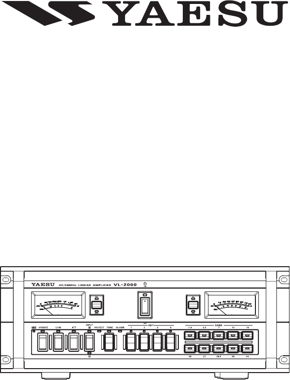
HF/50 MHz Linear aMpLiFire
VL-2000
Operating ManauL
VERTEX STANDARD CO., LTD.
4-8-8 Nakameguro, Meguro-Ku, Tokyo 153-8644, Japan
VERTEX STANDARD
US Headquarters
10900 Walker Street, Cypress, CA 90630, U.S.A.
YAESU UK LTD.
Unit 12, Sun Valley Business Park, Winnall Close
Winchester, Hampshire, SO23 0LB, U.K.
VERTEX STANDARD HK LTD.
Unit 1306-1308, 13F., Millennium City 2, 378 Kwun Tong Road,
Kwun Tong, Kowloon, Hong Kong
VERTEX STANDARD (AUSTRALIA) PTY., LTD.
Tally Ho Business Park, 10 Wesley Court, East Burwood, VIC, 3151
FCC ID: K6620321X70
Vertex Standard Co., Ltd.

Contents
General Description ...................................................................................................................................................................1
Front Panel Controls & Switches ...............................................................................................................................................2
Rear Panel Connectors & Switches ...........................................................................................................................................4
Installation & Interconnections .................................................................................................................................................6
FTDX9000 Series ........................................................................................................................................................... 6
FTDX5000 ......................................................................................................................................................................7
FT-2000/D ......................................................................................................................................................................8
FT-950 .............................................................................................................................................................................9
FT-450/D ...................................................................................................................................................................... 10
FT-897/D ...................................................................................................................................................................... 11
FT-857/D ....................................................................................................................................................................... 12
Multi Connection .......................................................................................................................................................... 13
General Transceiver ..................................................................................................................................................... 14
Operation ................................................................................................................................................................................. 16
Preparations .................................................................................................................................................................. 16
Linear Amplier Operation.......................................................................................................................................... 17
Automatic Antenna Tuner Operation ........................................................................................................................... 18
SO2R (Single Operator Two Radios) Feature .............................................................................................................. 19
ANTENNA DIRECT Feature ...................................................................................................................................... 19
Trouble Shooting...................................................................................................................................................................... 20
Specications ........................................................................................................................................................................... 21
FCC ID: K6620321X70
Vertex Standard Co., Ltd.
1
VL-2000 Operating Manual
Congratulations! You are now the owner of the Yaesu VL-2000 Linear Amplier, which brings you leading-edge technol-
ogy for the ultimate in operating convenience and reliability. We appreciate your investment in Yaesu equipment, and wish
you many years of satisfying operation using your new amplier!
The VL-2000 is an all-solid-state linear amplier operating on the 160 through 6 meter amateur bands at a power output
level of 1500 Watts on all modes*. The VL-2000 includes a built-in antenna tuner with 470 memories for tuning data, and
microprocessor control of the tuning circuitry. The VL-2000 features input jacks for two different exciters, as well as ve
antenna jacks for connection of antennas for different bands.
The separate VP-2000 Power Supply Unit provides the +48 Volts required by the PA transistors, as well as all required
control voltages for the amplier. The VL-2000 normally is powered via 220 Volt AC mains, although it can be operated,
at the 500 Watt level, from 120 Volt AC power.
We encourage you to read this manual thoroughly before beginning installation and operation of your VL-2000 Linear
Amplier. The details regarding proper installation and operating advice contained in these pages will help you derive
maximum satisfaction from your new Yaesu equipment. Be certain to observe all due safety precautions when using this
high-power device!
General Description
Supplied AcceSSorieS
Item QuantIty
Antenna Cable (T9101600) ..................................................................................................................................1
Control Cable (T9101599) ...................................................................................................................................1
RCA Plug (P0091365) .........................................................................................................................................2
8-pin DIN Plug (P0090651) .................................................................................................................................1
Operating Manual ...............................................................................................................................................1
Warranty Card .....................................................................................................................................................1
FCC ID: K6620321X70
Vertex Standard Co., Ltd.
2VL-2000 Operating Manual
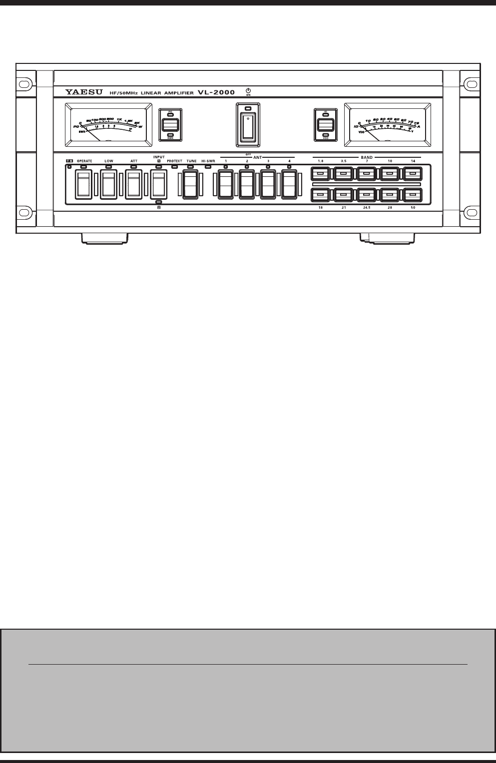
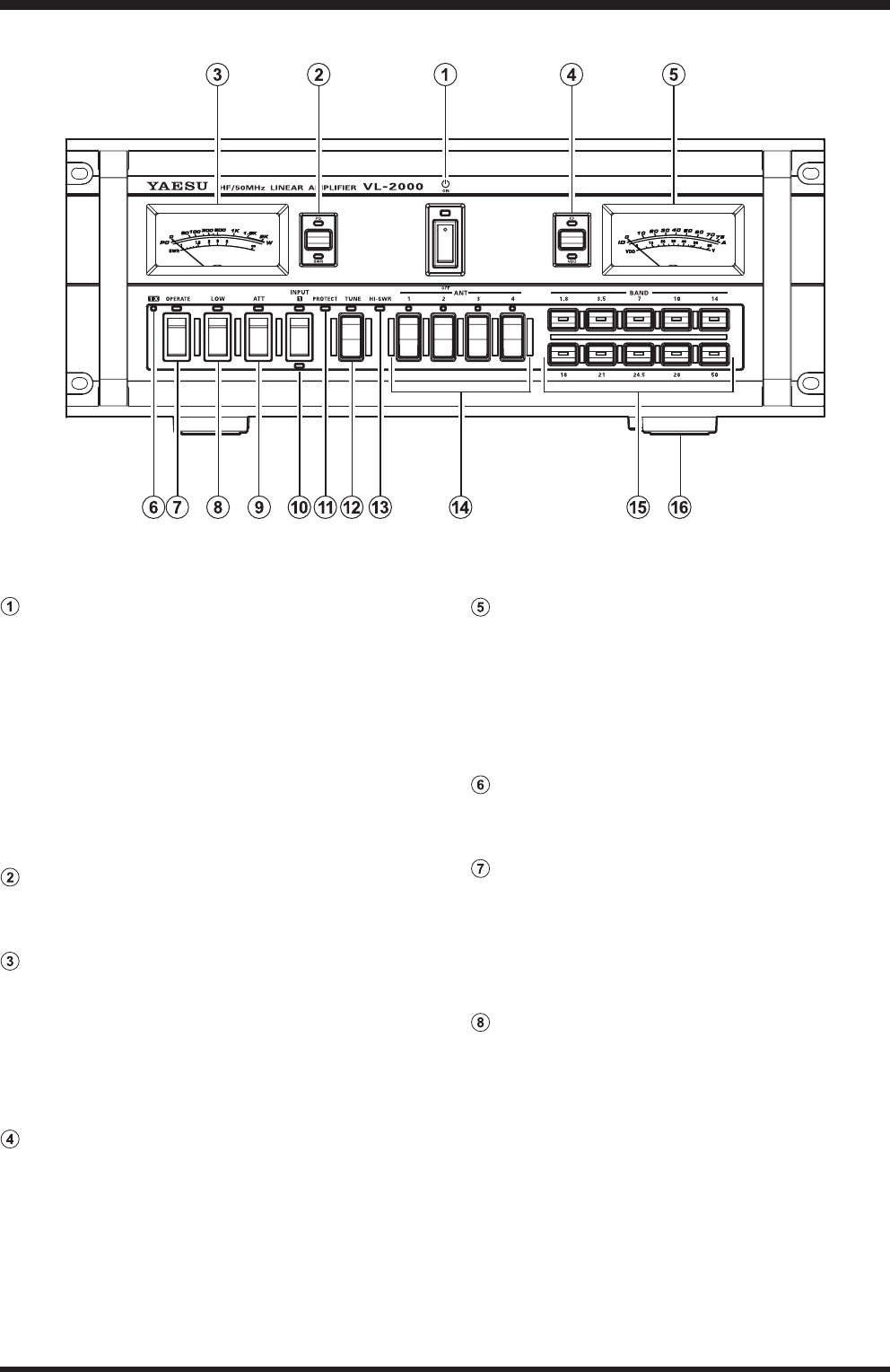
Front Panel Controls & Switches
POWER Switch
This switch turns the VL-2000 “on” and “off”.
When the VP-2000 [POWER] switch is set to the
“off” position, this switch will not function.
If using the Yaesu transceiver with a BAND DATA
Cable, the VP-2000 AC power will be remotely con-
trolled by the transceiver’s power switch when the
REMOTE switch on the rear panel of the VL-2000 is
set to “on”.
Caution: Never turn “off” this switch while transmit-
ting.
METER-1 Switch
Press this switch to toggle the METER-1 function be-
tween “PO” meter and “SWR” meter.
METER-1
This is the two functions (PO/SWR) meter which is
determined by the “METER-1” switch selection.
PO: Indicates the RF Power Output, from 0 to 2k
watts on transmit.
SWR: Indicates the antenna system observed stand-
ing wave ratio (SWR), from 1.0 to 5.0.
METER-2 Switch
Press this switch to toggle the METER-2 function be-
tween “ID” meter and “VDD” meter.
METER-2
This is the two functions (ID/VDD) meter which is
determined by the “METER-1” switch selection.
ID: Indicates the final amplifier drain current,
from 0 to 75 A.
VDD: Indicates the final amplifier drain voltage
(nominal value: 48 V).
TX Indicator
This indicator glows red when the VL-2000 is trans-
mitting.
OPERATE Switch
This switch turns the power amplifier section of the
VL-2000 “on” and “off”.
When the power amplier is activated, the LED will
glow red.
Note: This switch does not effect while transmitting.
LOW Switch
This switch selects the RF output power.
When in the “LOW” position, the RF output power
will be reduced to (approximately) 500 watts PEP, and
the LED will glow red.
Note: This switch does not effect while transmitting.
FCC ID: K6620321X70
Vertex Standard Co., Ltd.
3VL-2000 Operating Manual
Front Panel Controls & Switches
ATT Switch
This switch activates a 3 dB input RF power attenua-
tor, to reduce excessive input power from the exciter.
It should be “on” if exciter output exceeds 100 watt
PEP, as is the case when using the FTDX9000 series
transceiver. The LED will glow red, when this switch
is “on”.
Note: This switch does not effect while transmitting.
INPUT Switch
This switch selects the exciters which connected to
the INPUT1 and INPUT2 jacks on the rear panel.
The “INPUT1” or “INPUT2” LED will glow red to
indicate which exciter is in use.
Note: This switch does not effect while transmitting.
PROTECT LED
This LED blinks red when the Linear Amplier is ab-
normal.
TUNE Button
This is the on/off switch for the VL-2000’s Automatic
Antenna Tuner.
Press this button briey, places the antenna tuner in
line between the transmitter final amplifier and the
antenna connector (The LED will glow red, and re-
ception is not affected).
Press and hold this button for 1/2 second, while re-
ceiving in an a mature band, activates the transmitter
for a few seconds while the Automatic Antenna Tuner
rematches the antenna system impedance for mini-
mum SWR. The LED will blink red when the antenna
tuning is processing.
Pressing this button brief ly, while the Tuner is en-
gaged, will take the Automatic Antenna Tuner out of
the transmit line.
HI-SWR LED
This LED blinks red when the antenna system is ab-
normally high SWR condition (over 3.0:1) that cannot
be resolved by the Automatic Antenna Tuner.
When this LED blinks, the exciter output delivers to
the antenna connector directly without through a lin-
ear amplier.
Note: Check to be sure that you have the correct an-
tenna selected on the current operating band when
this LED blinks red. If so, you will need to check the
condition of the antenna, its coaxial cable and/or the
connectors on the cable so as to locate and correct
fault.
ANT Button
These momentary buttons select the antenna jack on
the rear panel, with the selection indicated by the red
LED in each button.
Note: These buttons does not effect while transmit-
ting.
BAND Button
These momentary buttons select the amateur band for
the operation, with the selection indicated by the LED
in each button.
If using the Yaesu transceiver with a BAND DATA
Cable, the VL-2000 operation band will be remotely
controlled by the transceiver’s BAND switch.
Note: These buttons does not effect while transmit-
ting.
Forefeet
These forefeet enable to extend the length of the fore-
foot for easy viewing by rotating the outer ring of the
forefeet.
FCC ID: K6620321X70
Vertex Standard Co., Ltd.
4VL-2000 Operating Manual
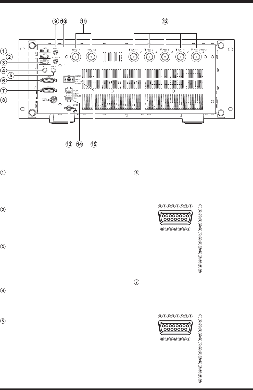
REMOTE Switch
When this switch is set to “on” position, the VL-
2000’s POWER switch will be controlled by the
transceiver’s POWER switch if you using a Yaesu
transceiver with a BAND DATA Cable.
DIRECT Switch
When this switch is set to “on” position, the exciter
power which is connected to the INPUT2 jack de-
liver to the ANTDIRECT connector directly, without
passing the Linear Amplier and Antenna Tuner.
SO2R Switch
When this switch is set to “on” position, the receiving
signal is sent to the both transceivers which is con-
nected to the INPUT1 and INPUT2 jack. This fea-
ture is very useful for the “SO2R” (Shingle Operator,
Two Radio) operation.
ALC-1 Potentiometer
This potentiometer adjusts the maximum output pow-
er of the VL-2000 when operating with the exciter
which is connected to the INPUT1 jack.
ALC-2 Potentiometer
This potentiometer adjusts the maximum output pow-
er of the VL-2000 when operating with the exciter
which is connected to the INPUT2 jack.
ACC-1 Jack
This D-SUB 15-pin Jack is connected to the Yaesu
transceiver which is connected to the INPUT1 jack,
to allow automatic band selection, T/R control, and
power on/off control.
ACC-2 Jack
This D-SUB 15-pin Jack is connected to the Yaesu
transceiver which connected to the INPUT 2 jack,
to allow automatic band selection, T/R control, and
power on/off control.
Rear Panel Connectors & Switches
: +13.5 V (IN)
: TX GND
: GND
: BAND DATA A
: BAND DATA B
: BAND DATA C
: BAND DATA D
: TX INH (OUT)
: F SET COMMON
: F SET 1
: F SET 2
: RX D (TTL Level)
: TX D (TTL Level)
: EXT ALC
: GND
: +13.5 V (IN)
: TX GND
: GND
: BAND DATA A
: BAND DATA B
: BAND DATA C
: BAND DATA D
: TX INH (OUT)
: F SET COMMON
: F SET 1
: F SET 2
: NC
: NC
: EXT ALC
: GND
FCC ID: K6620321X70
Vertex Standard Co., Ltd.

5VL-2000 Operating Manual
Rear Panel Connectors & Switches
BAND-DATA2 Jack
This 8-pin DIN Jack is connected to the Yaesu trans-
ceiver which is connected to the INPUT2 jack, to al-
low automatic band selection.
STBY2 Jack
When this RCA jack is shorted to ground, it put the
VL-2000 into the transmit mode. Connect this jack to
the TXGND jack of the exciter which is connected to
the “INPUT2” jack.
ALCOUT2 Jack
This RCA jack provide the ALC (output) voltage for
control of the exciter’s RF drive level which is con-
nected to the “INPUT2” jack.
INPUT1/2 Jacks
These type M (SO-239) jacks should be connected
through a supplied Antenna Cable to the (transmitting)
antenna jack of the transceivers.
ANT Jacks
Connect these type M (SO-239) jacks to your anten-
nas using large (RG-239 or larger) 50 ohm coaxial
cable with mating plugs (Type M: PL-259).
GND Terminal Post
Connect this terminal to a good earth ground using
the shortest practical length of heavy braided cable.
All other station equipment should be grounded to the
same ground system.
DCIN Connector
Connect this 8-pin connector to the DC OUT con-
nector on the Yaesu VP-2000 AC Power Supply. This
connector provides +48V DC supply voltage for the
power amplier of the VL-2000.
CONTROL Connector
Connect this 8-pin connector to the CONTROL con-
nector on the Yaesu VP-2000 AC Power Supply. This
connector provides ±12V DC supply voltage and con-
trol signals for the VL-2000.
: +13.5 V (IN)
: TX GND
: GND
: BAND DATA A
: BAND DATA B
: BAND DATA C
: BAND DATA D
: TX INH (OUT)
FCC ID: K6620321X70
Vertex Standard Co., Ltd.
6VL-2000 Operating Manual
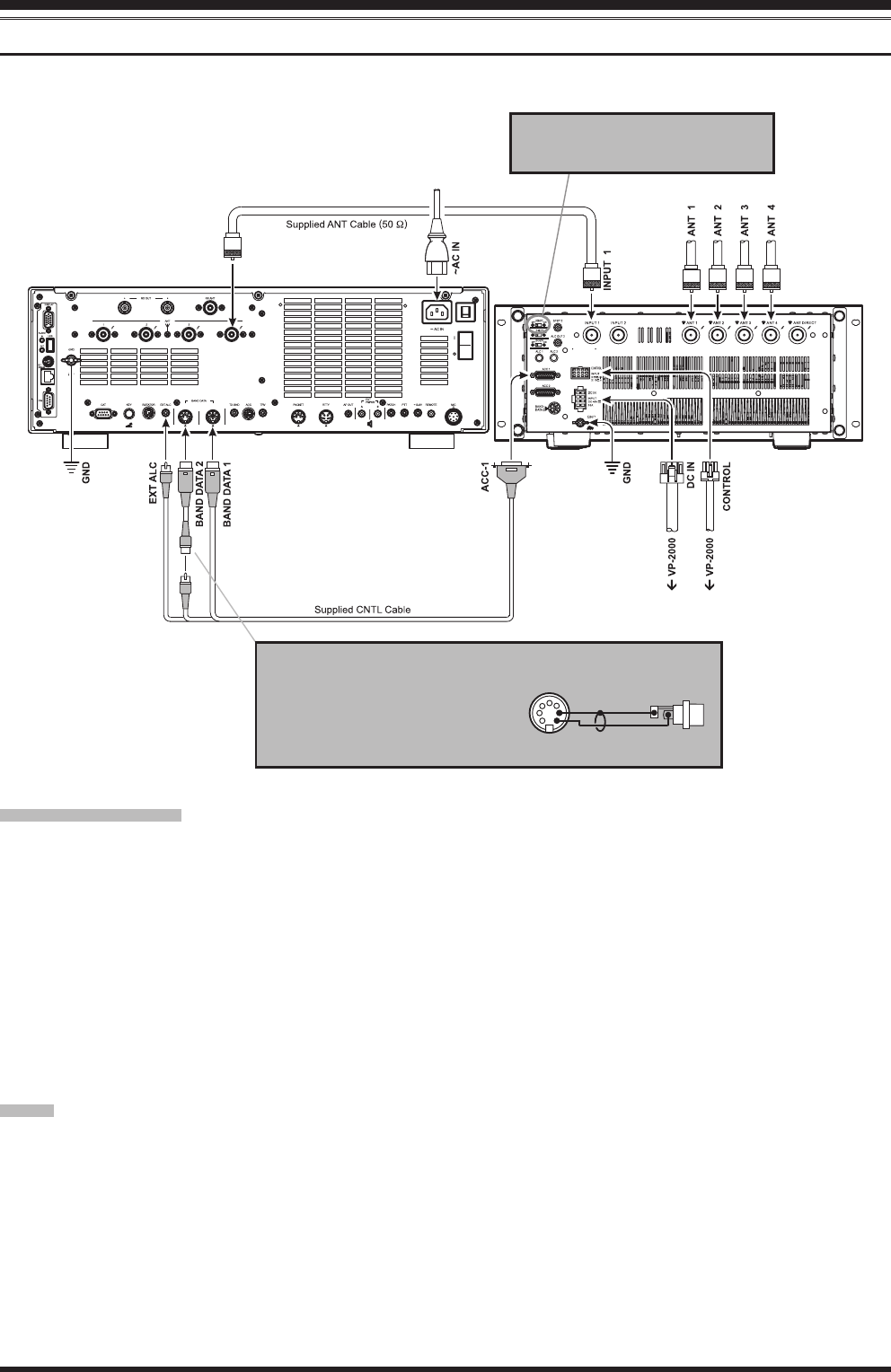
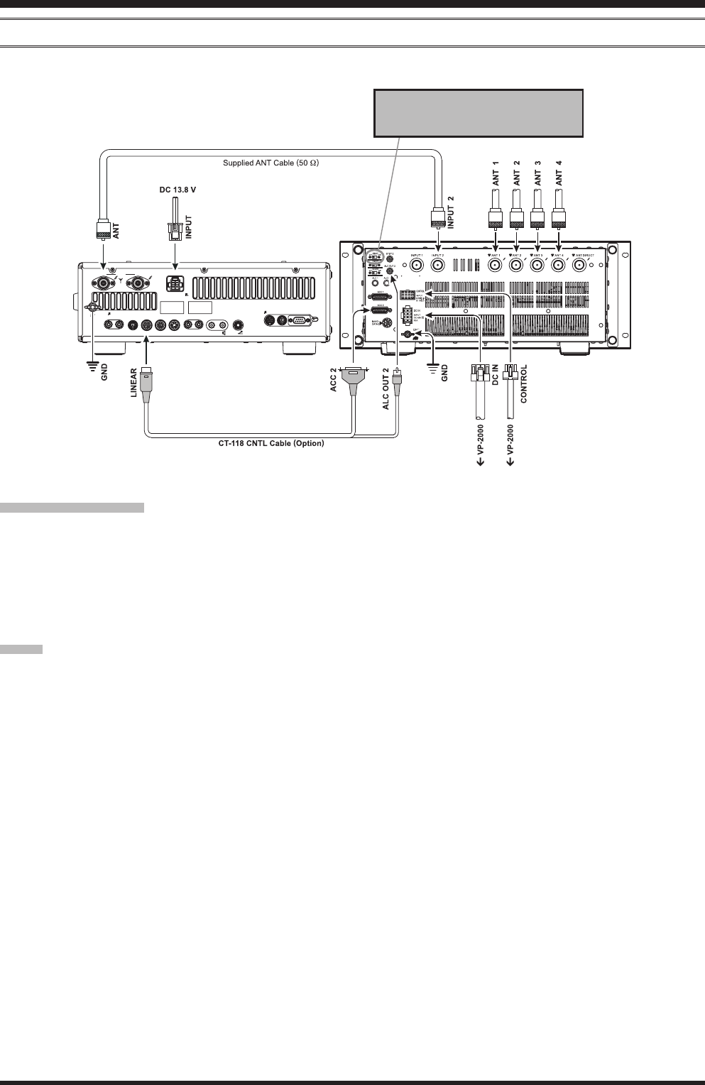
Installation & Interconnections
FTdX9000 SerieS
Be sure both FTDX9000 and VL-2000 are turned off, then follow the installation recommendation contained in the illus-
tration.
imporTAnT noTe !
r When operate the VL-2000 with the FTDX9000MP, should be set the ATT switch on the VL-2000 front panel to “on”
position, and set the maximum RF output power level to “200 W” via menu item “TX GNRL 173 TX MAX POW-
ER” on the FTDX9000MP. The 400 watt power output from the FTDX9000MP is far in excess of what is required to
drive the VL-2000 to its full rated output.
r When operate the VL-2000 with the FTDX9000D or FTDX9000Contest, should be set the ATT switch on the VL-
2000 front panel to “on” position. The 200 watt power output from the FTDX9000D or FTDX9000Contest is far in
excess of what is required to drive the VL-2000 to its full rated output.
r The ALC cable must be connected between the transceiver and VL-2000 to prevent overdrive of the amplier, and
especially to facilitate the proper operation of the protection circuitry if sudden antenna system problems should cause
the SWR to rise to dangerous levels.
r Do not attempt to connect or disconnect coaxial antenna cables when your hands are wet.
noTe
r When the VL-2000 POWER switch is turned “off”, the exciter output is delivered as follows:
¦ INPUT1 exciter: delivers to the ANT1 connector directly.
¦ INPUT2 exciter: delivers to the ANTDIRECT connector directly.
r If you want to link the VL-2000 and FTDX9000 series POWER switches, set the VL-2000 REMOTE switch to the
“on” position.
21
ANT
To link the FTDX9000 and VL-2000
POW ER switch, set the VL-2000
REMOTE switch to the “ON” position.
Make the Conversion Cable to show
illustration at the right with the 7-pin
DIN Plug which is supplied to the
FTDX9000 transceiver and the after
market’s RCA Jack.
Pin 7
Pin 3
TX REQ
GND
7-pin DIN Plug RCA Jack
converSion cAble
FCC ID: K6620321X70
Vertex Standard Co., Ltd.
7VL-2000 Operating Manual
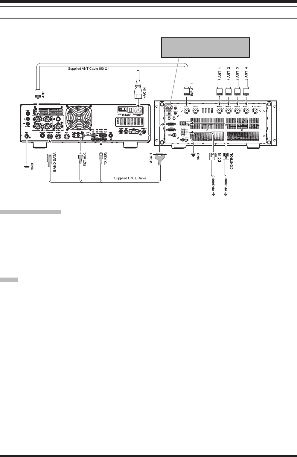
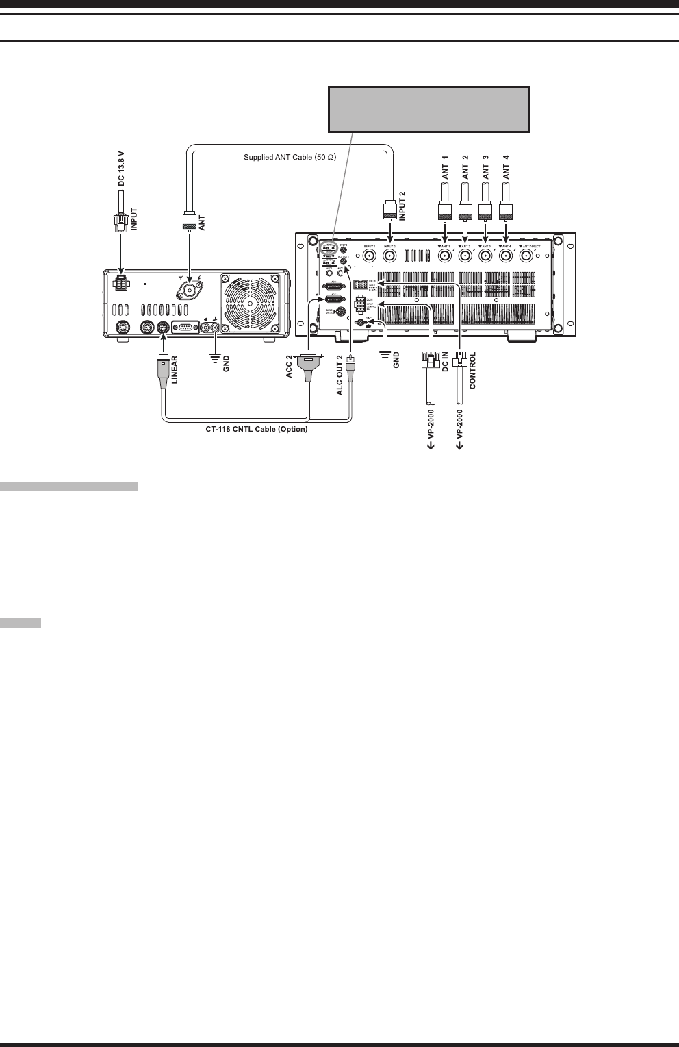
Installation & Interconnections
FTdX5000
Be sure both FTDX5000 and VL-2000 are turned off, then follow the installation recommendation contained in the illus-
tration.
imporTAnT noTe !
r When operate the VL-2000 with the FTDX5000, should be set the ATT switch on the VL-2000 front panel to “on” po-
sition. The 200 watt power output from the FTDX5000 is far in excess of what is required to drive the VL-2000 to its
full rated output.
r The ALC cable must be connected between the transceiver and VL-2000 to prevent overdrive of the amplier, and
especially to facilitate the proper operation of the protection circuitry if sudden antenna system problems should cause
the SWR to rise to dangerous levels.
r Do not attempt to connect or disconnect coaxial antenna cables when your hands are wet.
noTe
r When the VL-2000’s POWER switch is turned “off”, the exciter output is delivered as follows:
¦ INPUT1 exciter: delivers to the ANT1 connector directly.
¦ INPUT2 exciter: delivers to the ANTDIRECT connector directly.
r If you want to link the VL-2000 and FTDX5000 POWER switches, set the VL-2000 REMOTE switch to the “on”
position.
To link the FTDX5000 and VL-2000
POW ER switch, set the VL-2000
REMOTE switch to the “ON” position.
FCC ID: K6620321X70
Vertex Standard Co., Ltd.
8VL-2000 Operating Manual
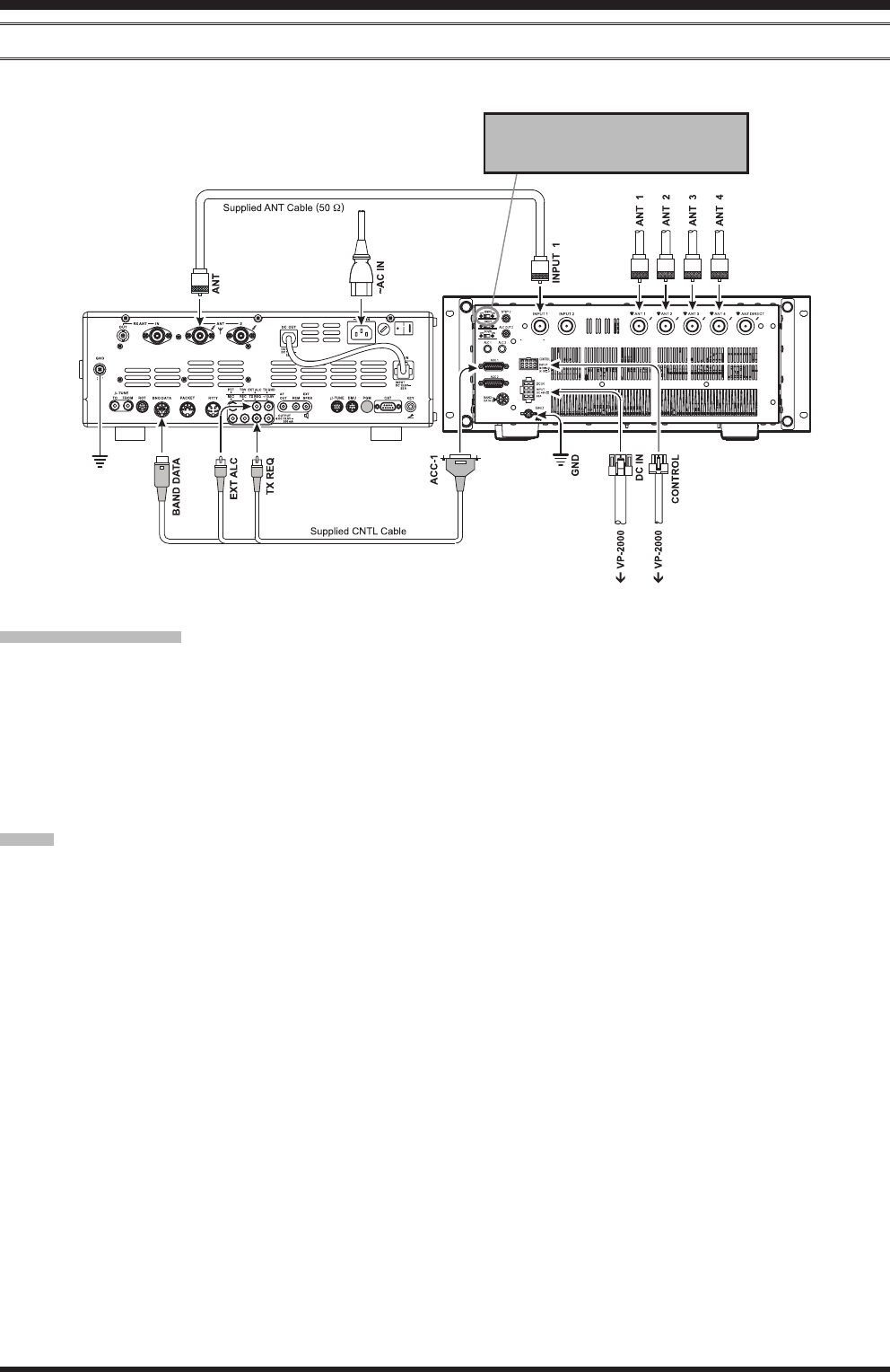
Installation & Interconnections
FT-2000/d
Be sure both FT-2000/D and VL-2000 are turned off, then follow the installation recommendation contained in the illus-
tration.
imporTAnT noTe !
r When operate the VL-2000 with the FT-2000D, should be set the ATT switch on the VL-2000 front panel to “on” po-
sition. The 200 watt power output from the FT-2000D is far in excess of what is required to drive the VL-2000 to its
full rated output.
r The ALC cable must be connected between the transceiver and VL-2000 to prevent overdrive of the amplier, and
especially to facilitate the proper operation of the protection circuitry if sudden antenna system problems should cause
the SWR to rise to dangerous levels.
r Do not attempt to connect or disconnect coaxial antenna cables when your hands are wet.
noTe
r When the VL-2000 POWER switch is turned “off”, the exciter output is delivered as follows:
¦ INPUT1 exciter: delivers to the ANT1 connector directly.
¦ INPUT2 exciter: delivers to the ANTDIRECT connector directly.
r If you want to link the VL-2000 and FT-2000/D POWER switches, set the VL-2000 REMOTE switch to the “on”
position.
To link the FT-2000/D and VL-2000
POW ER switch, set the VL-2000
REMOTE switch to the “ON” position.
FCC ID: K6620321X70
Vertex Standard Co., Ltd.
9VL-2000 Operating Manual
Installation & Interconnections
FT-950
Be sure both FT-950 and VL-2000 are turned off, then follow the installation recommendation contained in the illustra-
tion.
imporTAnT noTe !
r The FT-950 enables to connect only to the INPUT2 connector. Set the INPUT switch to the “INPUT2” side after as-
semble the equipment.
r The ALC cable must be connected between the transceiver and VL-2000 to prevent overdrive of the amplier, and
especially to facilitate the proper operation of the protection circuitry if sudden antenna system problems should cause
the SWR to rise to dangerous levels.
r Do not attempt to connect or disconnect coaxial antenna cables when your hands are wet.
noTe
r When the VL-2000’s POWER switch is turned “off”, the exciter output is delivered as follows:
¦ INPUT1 exciter: delivers to the ANT1 connector directly.
¦ INPUT2 exciter: delivers to the ANTDIRECT connector directly.
r If you want to link the VL-2000 and FT-950 POWER switches, set the VL-2000 REMOTE switch to the “on” posi-
tion.
TO
1ANT DC IN
2
FROM
GND ROT LINEAR TUNER
RTTY / PKT
PTT REC REM KEY
DMU CAT
PGM-SW
EXT
SPKR
INPUT: DC 13.8 V
22 A
-TUNE -TUNE
To link the FT- 9 5 0 and V L-20 00
POW ER switch, set the VL-2000
REMOTE switch to the “ON” position.
FCC ID: K6620321X70
Vertex Standard Co., Ltd.
10 VL-2000 Operating Manual
Installation & Interconnections
FT-450/d
Be sure both FT-450/D and VL-2000 are turned off, then follow the installation recommendation contained in the illus-
tration.
imporTAnT noTe !
r The FT-450/D enables to connect only to the INPUT2 connector. Set the INPUT switch to the “INPUT2” side after
assemble the equipment.
r The ALC cable must be connected between the transceiver and VL-2000 to prevent overdrive of the amplier, and
especially to facilitate the proper operation of the protection circuitry if sudden antenna system problems should cause
the SWR to rise to dangerous levels.
r Do not attempt to connect or disconnect coaxial antenna cables when your hands are wet.
noTe
r When the VL-2000 POWER switch is turned “off”, the exciter output is delivered as follows:
¦ INPUT1 exciter: delivers to the ANT1 connector directly.
¦ INPUT2 exciter: delivers to the ANTDIRECT connector directly.
r If you want to link the VL-2000 and FT-450/D POWER switches, set the VL-2000 REMOTE switch to the “on” po-
sition.
INPUT
DC 13.8V
22A
ANT
GND
EXT
SPKR
CATLIN EARTUN ERDATA
To link the F T- 45 0 an d VL-2000
POW ER switch, set the VL-2000
REMOTE switch to the “ON” position.
FCC ID: K6620321X70
Vertex Standard Co., Ltd.
11VL-2000 Operating Manual
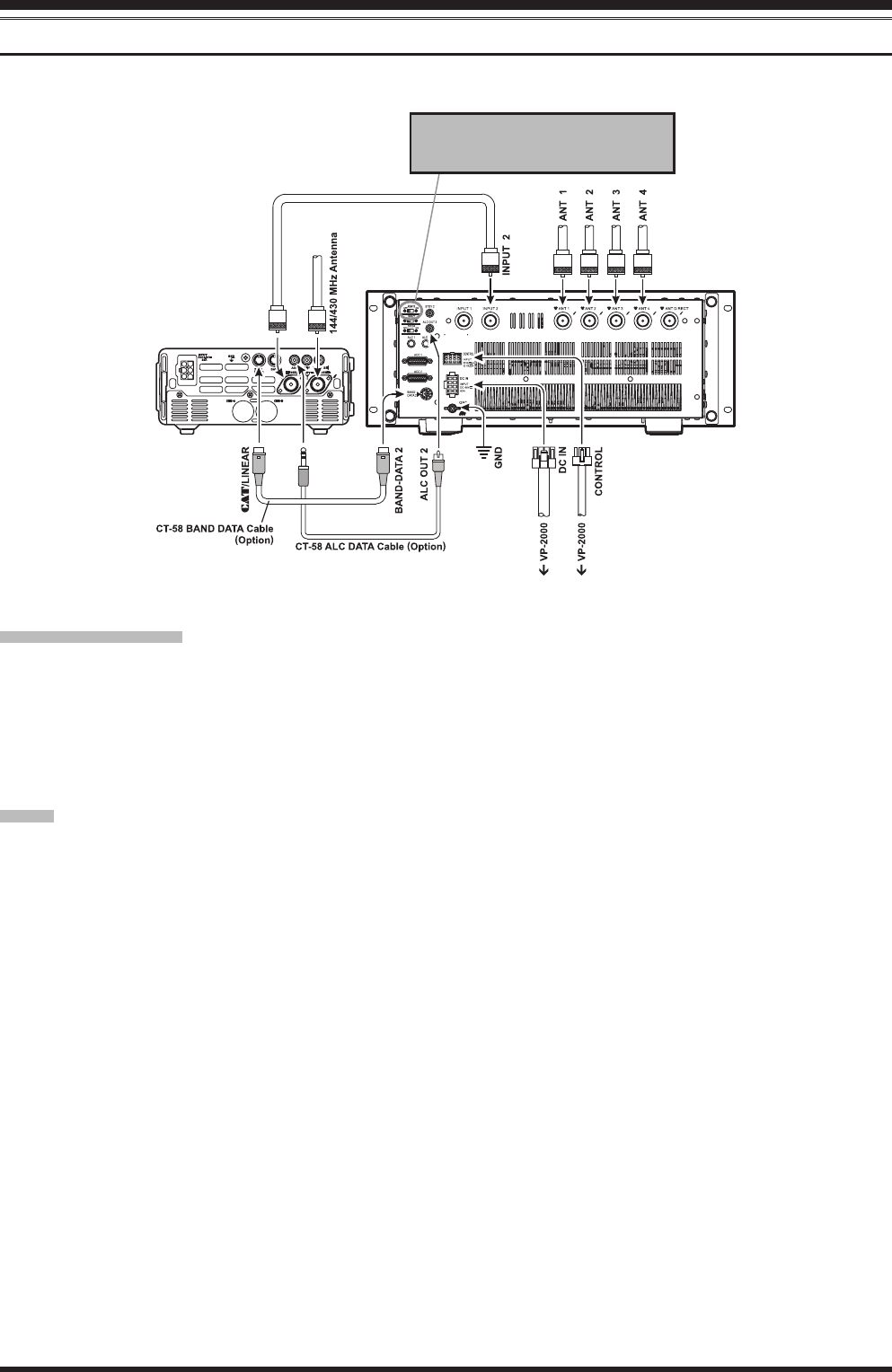
Installation & Interconnections
FT-897/d
Be sure both FT-897/D and VL-2000 are turned off, then follow the installation recommendation contained in the illus-
tration.
imporTAnT noTe !
r The FT-897/D enables to connect only to the INPUT2 connector. Set the INPUT switch to the “INPUT2” side after
assemble the equipment.
r The ALC cable must be connected between the transceiver and VL-2000 to prevent overdrive of the amplier, and
especially to facilitate the proper operation of the protection circuitry if sudden antenna system problems should cause
the SWR to rise to dangerous levels.
r Do not attempt to connect or disconnect coaxial antenna cables when your hands are wet.
noTe
r When the VL-2000’s POWER switch is turned “off”, the exciter output is delivered as follows:
¦ INPUT1 exciter: delivers to the ANT1 connector directly.
¦ INPUT2 exciter: delivers to the ANTDIRECT connector directly.
r If you want to link the VL-2000 and FT-897/D POWER switches, set the VL-2000 REMOTE switch to the “on” po-
sition.
GND
DATA
CAT /
LINEAR
ACC
CHG B
CHG A
HF/50MHz
KEY
144/430MHz
ANT
EXT SPKR
INPUT
22A
DC13.8V
To link the FT-897/D and VL-2000
POW ER switch, set the VL-2000
REMOTE switch to the “ON” position.
FCC ID: K6620321X70
Vertex Standard Co., Ltd.
12 VL-2000 Operating Manual
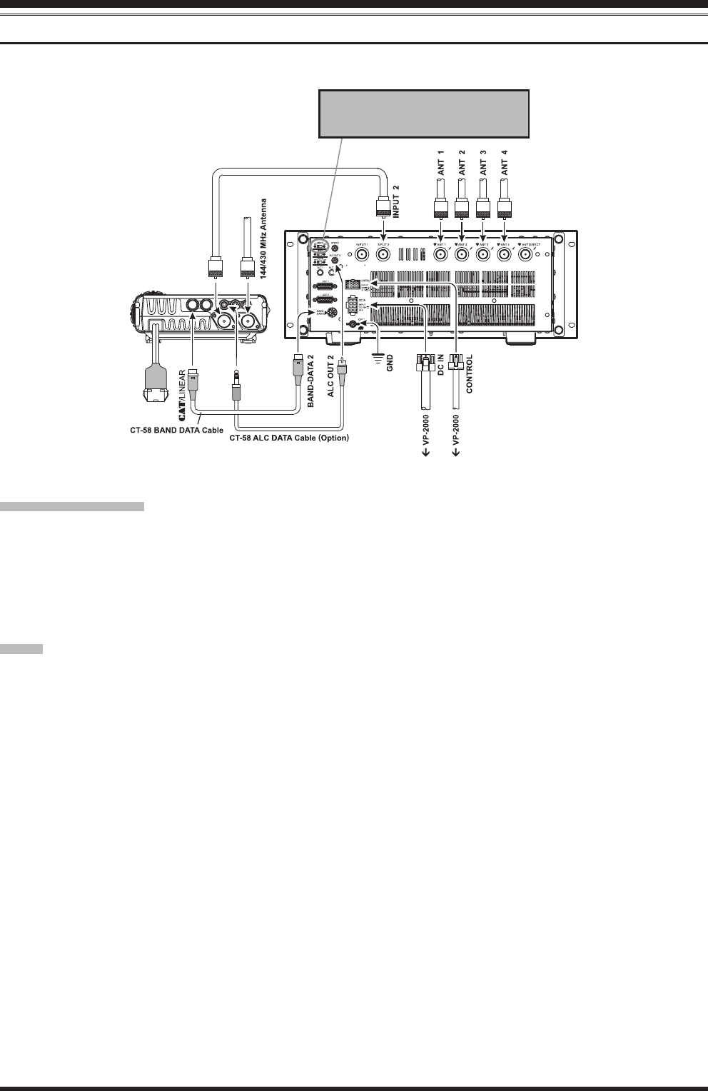
Installation & Interconnections
FT-857/d
Be sure both FT-857/D and VL-2000 are turned off, then follow the installation recommendation contained in the illus-
tration.
imporTAnT noTe !
r The FT-857/D enables to connect only to the INPUT2 connector. Set the INPUT switch to the “INPUT2” side after
assemble the equipment.
r The ALC cable must be connected between the transceiver and VL-2000 to prevent overdrive of the amplier, and
especially to facilitate the proper operation of the protection circuitry if sudden antenna system problems should cause
the SWR to rise to dangerous levels.
r Do not attempt to connect or disconnect coaxial antenna cables when your hands are wet.
noTe
r When the VL-2000 POWER switch is turned “off”, the exciter output is delivered as follows:
¦ INPUT1 exciter: delivers to the ANT1 connector directly.
¦ INPUT2 exciter: delivers to the ANTDIRECT connector directly.
r If you want to link the VL-2000 and FT-857/D POWER switches, set the VL-2000 REMOTE switch to the “on” po-
sition.
To link the FT-897/D and VL-2000
POW ER switch, set the VL-2000
REMOTE switch to the “ON” position.
FCC ID: K6620321X70
Vertex Standard Co., Ltd.
13VL-2000 Operating Manual
Installation & Interconnections
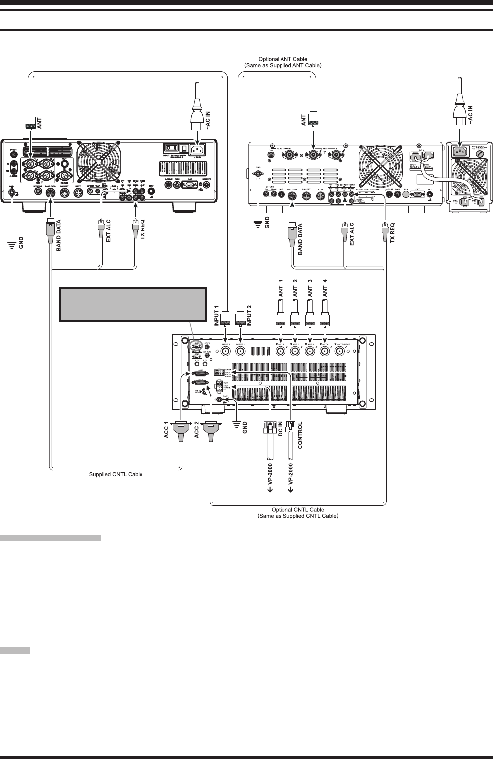
mulTi connecTion (eXAmple: FTdX5000 & FT-2000)
Be sure all equipment are turned off, then follow the installation recommendation contained in the illustration.
imporTAnT noTe !
r When connect the 100 watt transceiver and 200 watt transceivers to the VL-2000 together, reduce the RF output
power of the 200 watt transceiver to 100 watt by the Menu Mode Item. For example above, set the maximum RF output
power level to “100 W” via menu item “170 TGEN MAX PWR” on the FTDX5000.
r The ALC cable must be connected between the transceiver and VL-2000 to prevent overdrive of the amplier, and
especially to facilitate the proper operation of the protection circuitry if sudden antenna system problems should cause
the SWR to rise to dangerous levels.
r Do not attempt to connect or disconnect coaxial antenna cables when your hands are wet.
noTe
r When the VL-2000’s POWER switch is turned “off”, the exciter output is delivered as follows:
¦ INPUT1 exciter: delivers to the ANT1 connector directly.
¦ INPUT2 exciter: delivers to the ANTDIRECT connector directly.
r If you want to link the VL-2000 and transceiver POWER switches, set the VL-2000 REMOTE switch to the “on”
position. When turn “on” one of the transceiver, the VL-2000 becomes “on” automatically.
To link the Transceiver’s and VL-2000
POW ER switch, set the VL-2000
REMOTE switch to the “ON” position.
FCC ID: K6620321X70
Vertex Standard Co., Ltd.
14 VL-2000 Operating Manual
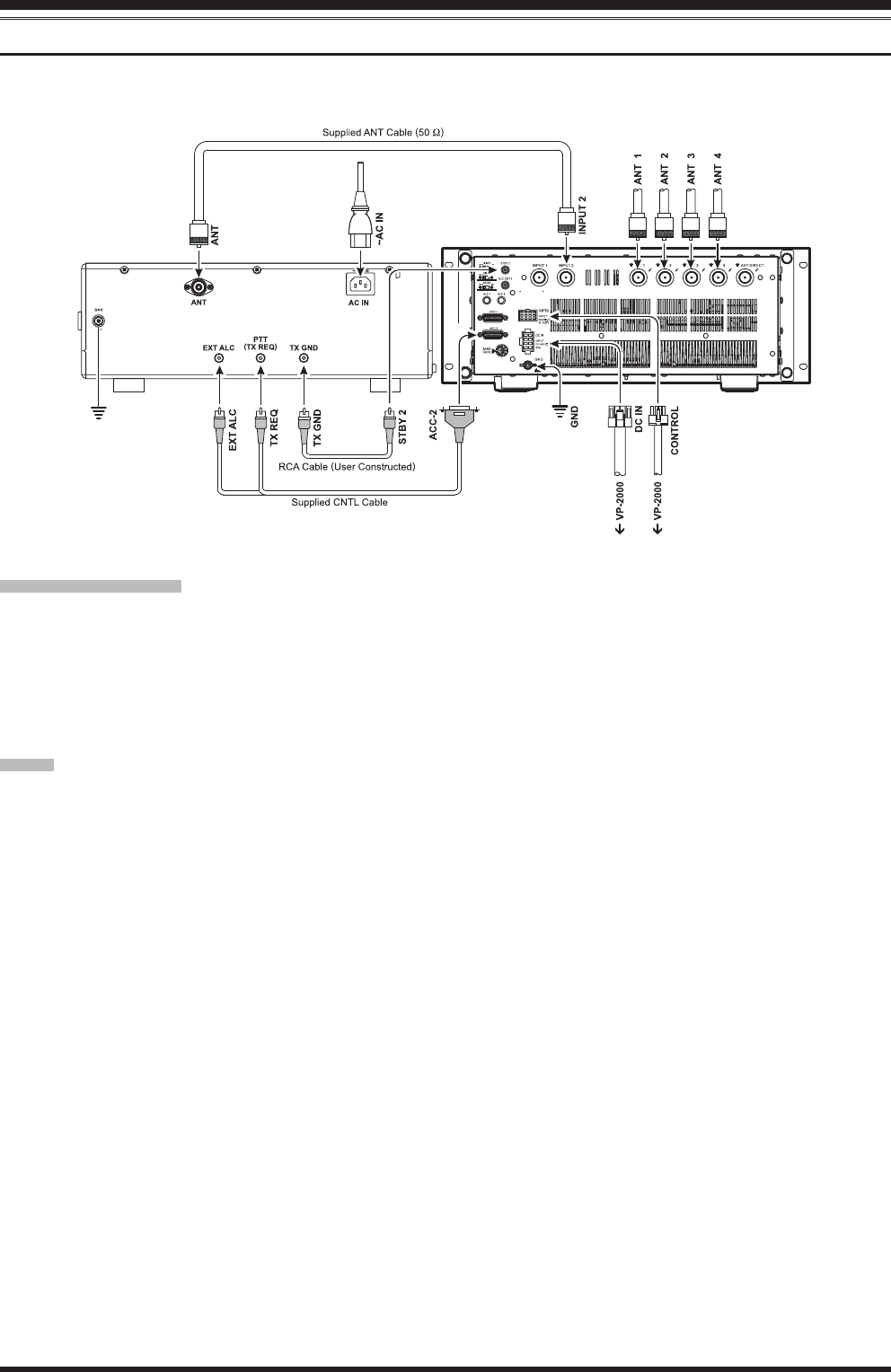
Installation & Interconnections
GenerAl TrAnSceiver
Be sure both transceiver and VL-2000 are turned off, then follow the installation recommendation contained in the illus-
tration.
imporTAnT noTe !
r The general transceiver enables to connect only to the INPUT2 connector. Set the INPUT switch to the “INPUT2”
side after assemble the equipment.
r The ALC cable must be connected between the transceiver and VL-2000 to prevent overdrive of the amplier, and
especially to facilitate the proper operation of the protection circuitry if sudden antenna system problems should cause
the SWR to rise to dangerous levels.
r Do not attempt to connect or disconnect coaxial antenna cables when your hands are wet.
noTe
r When the VL-2000 POWER switch is turned “off”, the exciter output is delivered as follows:
¦ INPUT1 exciter: delivers to the ANT1 connector directly.
¦ INPUT2 exciter: delivers to the ANTDIRECT connector directly.
VL-2000
FCC ID: K6620321X70
Vertex Standard Co., Ltd.

15VL-2000 Operating Manual
Installation & Interconnections
noTe
FCC ID: K6620321X70
Vertex Standard Co., Ltd.

16 VL-2000 Operating Manual
Operation
prepArATionS
To transmit the high quality RF signal, adjust the ALC voltage in the following procedures, before operating.
imporTAnT noTe
r Conrm whether wiring does not have a miss wiring again.
r Connect the Dummy load which have an enough RF Input Power to the Antenna Connector on the rear panel of
the VL-2000.
r The VL-2000 requires 220 Volt AC power for 1.5 kW operation, while 117 Volt AC power is possible at the 500
W power output.
r When connect the FTDX9000D/Contest, FTDX5000, FT-2000D (200 W transceiver) to the VL-2000, set the ATT
switch on the VL-2000 front panel to “on” position to reduce the input power of the VL-2000.
r When connect the FTDX9000MP (400 W transceiver) to the VL-2000, set the ATT switch on the VL-2000 front
panel to “on” position, and set the maximum RF output power level to “200 W” via menu item “TX GNRL 173
TX MAX POWER” on the FTDX9000MP to reduce the input power of the VL-2000.
1. Set the INPUT switch to the position which is con-
nected to the exciter.
2. Rotate the ALC-1 (or ALC-2: determine to the exciter
connected) potentiometer fully counter clockwise.
3. Set the operating band of the exciter and VL-2000 to
the same operating band.
Note: If you connect the supplied CNTL Cable be-
tween the transceiver and VL-2000, the operating
band of the VL-2000 will automatically set when you
set the transceiver’s operating band.
4. Set the operation mode of the exciter to the “CW”
mode.
5. Set the OPERATE switch and TUNE button to both
“off”.
6. Set the METER-1 function to “PO” by pressing the
METER-1 switch (The “PO” LED will glow red).
7. Press the one of the ANT (1 - 4) buttons correspond-
ing to the antenna jack connecting the Dummy Load.
8. Press the PTT switch of the exciter, then adjust the
RF output power level of the exciter so that the ex-
citer’s PO meter reading becomes 100 watt (or 200
watt).
Note: Refer to the operating manual of the exciter for
the adjustment method of the RF output power level
of the exciter.
9. Release the PTT switch, then set the OPERATE
switch to “on” (The “OPERATE” LED will glow red).
10. Set the ATT switch to “on” (The “ATT” LED will
glow red), if the exciter output which you connected
exceeds 100 watts PEP.
Caution !: Do not forget this operation, as it may
cause a serious damage to the VL-2000 by an over
injection.
11. Press the PTT switch of the exciter again, then adjust
the ALC-1 (or ALC-2) potentiometer so that the ME-
TER-1 (“PO” meter) reading becomes 1500 watt.
12. Release the PTT switch.
13. The ALC voltage adjustment is now completed.
AbouT The ATT SwiTch
The VL-2000 requires input drive power of 80 -
100 watts.
When connect the exciter having exceed 100
watts PEP (such as our FTDX9000D/Contest,
FTDX5000, or FT-2000D), set the ATT switch on
the VL-2000 front panel to “on” position to reduce
the input power of the VL-2000.
FAn operATion
The VL-2000 cooling fans are thermostatically
controlled. It turns at low speed at the time of the
transmission start, and then fan speed rises in ac-
cordance with the temperature rise in the case.
The cooling fan operation links the OPERATE
switch. When turn “off” the OPERATE switch
(mean disabling the Linear Amplier), the cooling
fan turns “off” for enabling the quiet monitoring.
FCC ID: K6620321X70
Vertex Standard Co., Ltd.

17VL-2000 Operating Manual
Operation
lineAr AmpliFier operATion
Before operating, please check the following items:
r Conrm whether wiring does not have a miss wiring again.
r Conrm that the AC power plug connect to 220 Volt AC power directly. The VL-2000 requires 220 Volt AC power for
1.5 kW operation
r Conrm that the ATT switch is set to “on” position, when connect the exciter having exceed 100 watts PEP.
r Conrm that the antenna SWR is less than 1.5:1.
1. Turn the VP-2000 POWER switch “on”, then turn
the VL-2000 POWER switch “on”.
2. Turn the transceiver’s POWER switch “on”.
If using a Yaesu transceiver with a BAND DATA Ca-
ble, and the REMOTE switch on the rear panel of the
VL-2000 is set to “on”, the VP-2000 AC power will
be remotely controlled by the transceiver’s POWER
switch.
3. Set the INPUT switch to the position which is con-
nected to the exciter.
4. Select the amateur band of the transceiver you wish to
operate on.
If using a Yaesu transceiver with a BAND DATA
Cable, band selection will occur automatically when-
ever you change bands on the transceiver. Otherwise,
select the amateur band of the VL-2000 to same as
the transceiver.
5. Select the operating mode of the transceiver you wish
to operate on.
6. Set the OPERATE switch to “on”. The “OPERATE”
LED will glow red.
7. Press and hold the TUNE button for 1/2 second to
begin automatic tuning. The transmitter will be en-
gaged, and the red TUNE LED will blink while tun-
ing is in progress. When the optimum tuning point
has been reached, the transceiver (and VL-2000) will
return to receive, and the TUNE LED will glow red
steadily (instead of blinking).
8. For SSB and CW operation, make sure to adjust the
Microphone Gain and/or Drive control on the trans-
ceiver for proper ALC indication on the transceiver
ALC meter, as described in the transceiver manual.
Generally, for SSB, the ALC meter indication should
not deflect beyond a certain ALC limit (the “ALC”
zone on the transceiver’s meter) on voice peaks; on
CW, the ALC indication should be just enough to
cause slight meter deection. Higher ALC levels may
produce distortion or key clicks, without producing
any additional power output.
In the CW mode, the VL-2000 allows you to full
break-in operation. However, the full break-in opera-
tion may give the stress to the T/R switching relays.
For FM, SSTV, RTTY, or Packet operation, You may
enable 1.5 kW operations, if the following condition is
satised.
r Normal Temperature: +41 °F to +95 °F
(+5 °C to +35 °C)
r Normal humidity (45 % to 85 %)
r Side Clearance: 10 inches (25 cm)
r Rear Clearance: 12 inches (30 cm).
Otherwise, press the LOW switch to select the LOW
power condition to prevent the overheating during
continuous operation.
For AM operation, adjust the Drive or RF Power
control on the transceiver so that the METER-1 (“PO”
meter) on the VL-2000 does not exceed 375 watts (on
1.5 kW operation) or 125 watts (on 500 watt opera-
tion) when transmitting a carrier.
operATinG precAuTionS
Summarized below are some precautions to adhere to in order to ensure long life and trouble-free operation with
the VL-2000.
r Do not turning the POWER switch “on” or “off” while transmitting.
r When changing bands, always make certain that the VL-2000 is set for the same band as the transceiver before
transmitting, and that the proper antenna is connected.
Remember that, when the VL-2000 is switched “off” the INPUT-1 jack is automatically connected to the ANT
1 jack and the INPUT-2 jack is automatically connected to the ANTDIRECT jack.
r Reduce the drive power (set the ATT switch to “on”), if the exciter output which you connected exceeds 100
watts PEP.
FCC ID: K6620321X70
Vertex Standard Co., Ltd.
18 VL-2000 Operating Manual
Operation
AuTomATic AnTennA Tuner operATion
The Automatic Antenna Tuner built into the VL-2000 is crafted to ensure a 50-Ohm load for the nal amplier stage of
the linear amplier. We recommend the Automatic Antenna Tuner be used whenever you operate the VL-2000.
Advice:
r The VL-2000 Automatic Antenna Tuner, being located inside the station, only adjusts the impedance presented to the
transmitter at the station end of your coaxial cable feedline. It does not “tune” the SWR at the antenna feedpoint itself.
When designing and building your antenna system, we recommend that every effort be made to ensure a low SWR at
the antenna feedpoint.
r The VL-2000 Automatic Antenna Tuner includes 470 memories for tuning data. These memory allocation is described
in the bottom chart.
r The VL-2000 Automatic Antenna Tuner is designed to match impedances within the range of 16.5 Ohms to 150 Ohms,
corresponding to an SWR of 3:1 or less on the HF amateur bands (6 meter amateur band: 25 Ohms to 100 Ohms, corre-
sponding to an SWR of 2:1 or less). Accordingly, simple non-resonant whip antennas, along with random-length wires
and the “G5RV” antenna (on most bands) may not be within the impedance matching range of the Automatic Antenna
Tuner.
r The VL-2000 Automatic Antenna Tuner is located between the nal amplier and the rear-panel antenna jack; recep-
tion is not affected by the Automatic Antenna Tuner.
1. Conrm the operating band of the VL-2000 is same
as the exciter.
2. Press the TUNE button briey to place the Automatic
Antenna Tuner in the transmit line. The TUNE LED
will glow red.
3. Press and hold the TUNE button for 1/2 second to
begin automatic tuning. The transmitter will be en-
gaged, and the red TUNE LED will blink while tun-
ing is in progress. When the optimum tuning point
has been reached, the transceiver (and VL-2000) will
return to receive, and the TUNE LED will glow red
steadily (instead of blinking).
4. To disconnect the Automatic Antenna Tuner
from the transmit line, press the TUNE button briey.
The TUNE LED will turn off, confirming that the
Automatic Antenna Tuner has been turned off. In the
“off” mode, the transceiver will be directly connected
to the coaxial cable connected to your antenna, and it
will operate based on whatever impedance is present
at the station end of the coax.
memory chAnnel AllocATionS
bAnd memory chAnnel STep
1.8 MHz 20 channels for each ANT Jack (x5) 10 kHz
3.5 MHz 25 channels for each ANT Jack (x5) 20 kHz
7 MHz 6 channels for each ANT Jack (x5) 50 kHz
10 MHz 1 channel for each ANT Jack (x5) ---
14 MHz 5 channels for each ANT Jack (x5) 100 kHz
18 MHz 1 channel for each ANT Jack (x5) ---
21 MHz 6 channels for each ANT Jack (x5) 100 kHz
24 MHz 1 channel for each ANT Jack (x5) ---
28 MHz 9 channels for each ANT Jack (x5) 200 kHz
50 MHz 20 channels for each ANT Jack (x5) 200 kHz
Advice
The VL-2000 Automatic Antenna Tuner makes a
note of the positions of the tuning capacitors and
the selected inductors when the tuning result is
better than SWR 1.5:1. This eliminates the need
to re-tune every time you return to a frequency on
which you already have completed the tuning pro-
cess.
noTe
The VL-2000 Automatic Antenna Tuner does not
tuning in the following situations:
r The exciter (transceiver) is not transmitted.
r No carrier.
r Low injection level.
r Antenna SWR is more than 3.0: 1.
(short-circuit or open-circuit)
r Tuning result is more than 3.0: 1.
reSeTTinG The AnTennA TuninG dATA
The VL-2000 can be reset so as to clear the an-
tenna tuner tuning data; this will be reset to the
factory default.
To reset the Antenna Tuning Data, press and hold
in the TUNE button while you turn the VL-2000
on.
FCC ID: K6620321X70
Vertex Standard Co., Ltd.

19VL-2000 Operating Manual
Operation
So2r FeATure
The SO2R (Single Operator Two Radios) feature allows
you to receive the two signals by the two transceivers
simultaneously, when connects the two radios to the VL-
2000. Furthermore, you to operate the VL-2000 without
changing the INPUT switch. The VL-2000 switches the
input to the transceiver side which transmitted automati-
cally, regardless the INPUT switch setting.
To activate the SO2R feature, turn “on” the SO2R switch
on the rear panel of the VL-2000.
noTe
r The VL-2000 Automatic Antenna Tuner works
only to the transceiver which connected to the
INPUT jack that is determined by the INPUT
switch.
r Cannot select the same antenna in INPUT 1
and INPUT2 while SO2R feature is activated.
Advice
Even if the SO2R switch is “off”, you can con-
nect the two transceivers deservedly. However,
you must switch the INPUT switch to the position
which is the transceiver that is transmitted manu-
ally and you can not receive the signal with the
other transceiver while the transceiver is transmit-
ted.
AnTennA direcT FeATure
The ANTENNA DIRECT feature outputs the INPUT
2 signal to the ANTDIRECT jack directly after having
passed the Linear Amplier and the Automatic Antenna
Tuner. As a result, the transmit signal does not pass a
complicated antenna change circuit, to keep the loss at
the minimum.
To activate the ANTENNA DIRECT feature, turn “on”
the DIRECT switch on the rear panel of the VL-2000.
imporTAnT noTe
When activates the ANTENNA DIRECT feature,
the all ANT LED (ANT1 ~ ANT4) turns “off”,
conrming that the ANTENNA DIRECT feature
has been activated.
FCC ID: K6620321X70
Vertex Standard Co., Ltd.
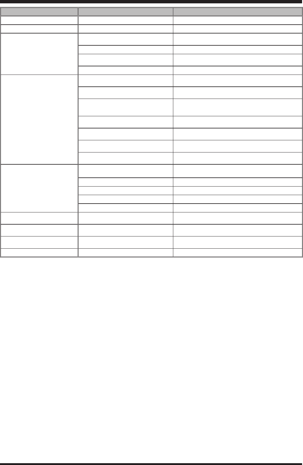
20 VL-2000 Operating Manual
SympTom probAble cAuSe remedy
Fails to power up. POWER Cables. Check the connections of the POWER Cables.
Operating band does not change. BANDDATA Cable or CNTL Cable. Check the connections of the BANDDATA Cable.
TX power output does not appear. Connection Cable between the transceiver
and VL-2000.
Check the connections of the Connection cable between the
transceiver and VL-2000.
Antenna Cable. Check the connections of the Antenna Cable.
INPUT Switch. Set the INPUT switch to the position where the transceiver is
connected.
OPERATE Switch. Turn “on” the OPERATE switch.
TX power output does not appear.
(PROTECT LED blinks red)
Excessive the exciter power.
(ATT LED blinks red)
r Reduce the exciter power to the 100 watts.
r Turn “on” the ATT switch.
Excessive the output power.
(PO METER LED blinks red)Check the connections of the ALC cable.
Incorrect the operating band or out from the
amateur band.
(one of the BAND LED blinks red)
r Set the BAND switch to the correct band.
r Set the transceiver’s frequency in the amateur band.
High Temperature of the Power Transistor. Stop the transmission immediately, then wait till temperature
of the Power Amplier falls.
Unbalance the power combine circuit of the
nal transistor. (OPERATE LED blinks red)
Stop the transmission immediately, then contact your Vertex
Standard dealer.
High or Low drain voltage.
(VD METER LED blinks red)
Stop the transmission immediately, then contact your Vertex
Standard dealer.
Excessive the drain current of the Power
Transistor. (IDD METER LED blinks red)
Stop the transmission immediately, then contact your Vertex
Standard dealer.
Low Transmit Power Connection Cable between the transceiver
and VL-2000.
Check the connections of the Connection Cable between the
transceiver and VL-2000.
Lower exciter power. Adjust the output power of the exciter.
ALC voltage. Adjust the ALC voltage.
Antenna miss-matching. Adjust the antenna matching (Set the SWR to better than 2.0:1).
Low AC power. Prepare 220 V AC for 1.5 kW operation.
Antenna Tuner does not operate. Connection Cable between the transceiver
and VL-2000.
Check the connections of the Connection Cable between the
transceiver and VL-2000.
HI-SWR LED glows red. Antenna miss-matching.
(SWR is more than 2.0:1) Adjust the antenna matching.
HI-SWR LED blinks red. Antenna miss-matching.
(SWR is more than 3.0:1)
r Adjust the antenna matching.
r Check the connections of the Antenna Cable.
ATT LED blinks red. Excessive the exciter power. Turn “on” the ATT switch.
Trouble Shooting
FCC ID: K6620321X70
Vertex Standard Co., Ltd.

21VL-2000 Operating Manual
GenerAl
Frequency Coverage: 1.8 MHz ~ 50 MHz Amateur Bands
Operating Mode: SSB, CW, AM, FM, RTTY
Input: INPUT 1/INPUT 2 (Two System)
Input Impedance: 50 W, unbalanced, Type-M connector
Excitation Power: 100 watt or 200 watt (@ATT ON)
Output: ANT 1 ~ ANT 4 (Four System) plus
ANT DIRECT (Sub Antenna System: INPUT 2 1 ANT DIRECT)
Output Impedance: 50 W, unbalanced, Type-M connector
Power Output: 1500/500 Watts (HI/LOW: 1.8 MHz ~ 28 MHz Amateur Bands)
1000/500 Watts (HI/LOW: 50 MHz Amateur Bands)
@ 220V AC Input to VP-2000 Power Supply
500 Watts (1.8 MHz ~ 50 MHz Amateur Bands)
@ 120V AC Input to VP-2000 Power Supply
Continuous Transmission Period: 100% @ 1500 Watts
Spurious Radiation: better than –60 dB @ 1.8 - 28 MHz Amateur Bands
better than –73 dB @ 50 MHz Amateur Band
Operating Band Change: Manual/Automatic (Automatic: requires the BAND DATA Cable)
Final Transistor: VRF2933 x 8
Final Amplier Circuit Type: Class-AB, Push-pull Circuit, Power Combine
Cooling System: Forced air-cooling (Variable wind velocity)
Operating Temperature Range: +14 °F ~ +104 °F (–10 °C ~ +40 °C) @1500 Watts Operation
+14 °F ~ +122 °F (–10 °C ~ +50 °C) @500 Watts Operation
Case Size (WxHxD): 19” x 7” x 20” (482 x 177 x 508 mm)
Weight (Approx.): 53.4 lbs (24.2 kg)
AuTomATic AnTennA Tuner SecTion
Impedance Matching Range: 25 to 100 W, unbalanced @ 1.8 MHz Amateur Band
16.6 to 150 W, unbalanced @ 3.5 ~ 50 MHz Amateur Bands
Matching Time: less than 3 seconds
Matched SWR: 1.5:1 or better
Specications are subject to change, in the interest of technical improvement, without notice or obligations.
Specications
Part 15.21: Changes or modications to this device not expressly approved by Vertex Standard
could void the user’s authorization to operate this device.
FCC ID: K6620321X70
Vertex Standard Co., Ltd.

Copyright 2011
VERTEX STANDARD CO., LTD.
All rights reserved.
No portion of this manual
may be reproduced without
the permission of
VERTEX STANDARD CO., LTD.
FCC ID: K6620321X70
Vertex Standard Co., Ltd.