Yaesu Musen 20485X40 Amateur Radio with scanning receiver User Manual Operating Manual
Yaesu Musen Co., Ltd. Amateur Radio with scanning receiver Operating Manual
UserManual.wiki
>
Yaesu Musen
>
20485X40 User Manual
>
User Manual Part 1
Contents
1.
User Manual Part 1
2.
User Manual Part 2
User Manual Part 1
Navigation menu
Upload a User Manual
Namespaces
Wiki Guide
HTML
PDF
Info
Views
User Manual
Discussion / Help
Navigation
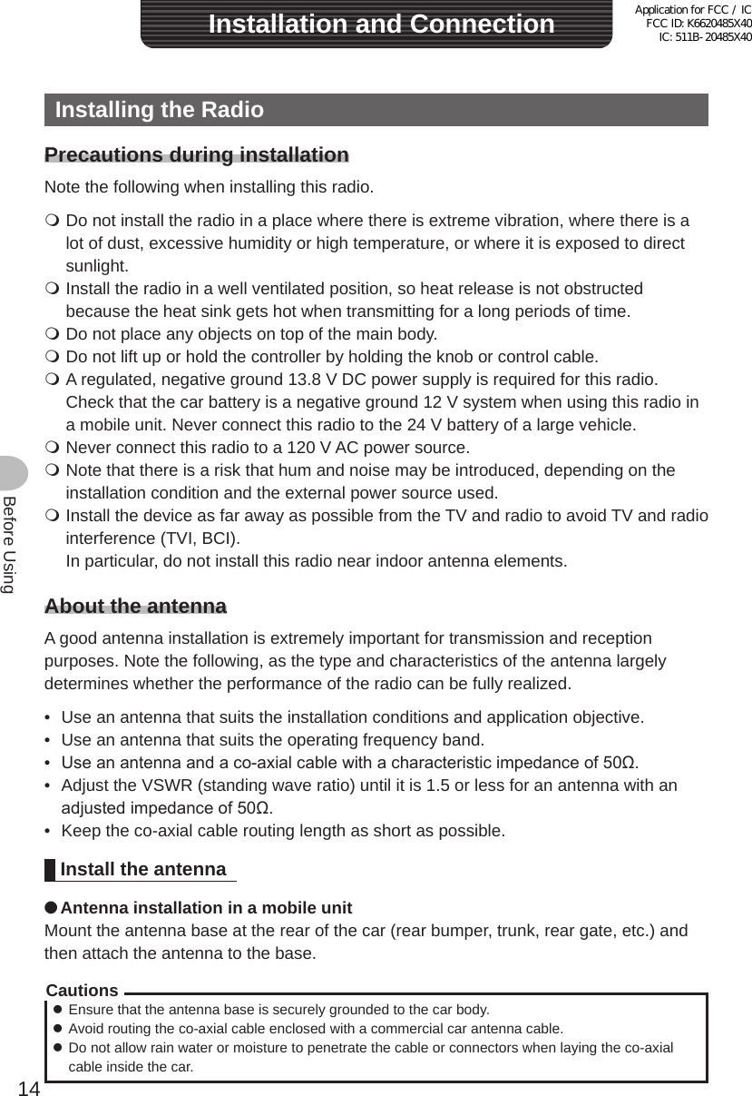
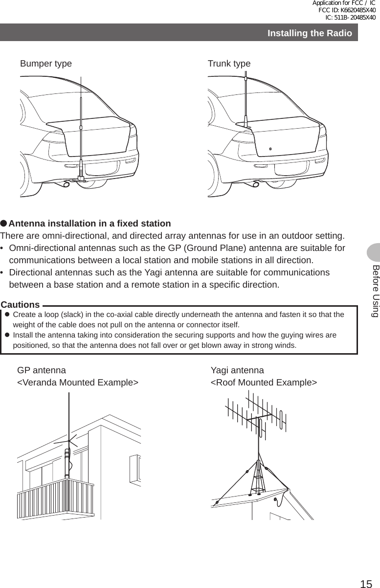
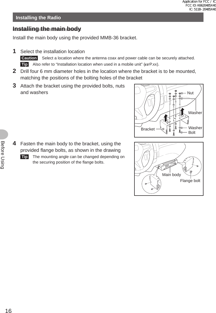
![4Before UsingIntroductionHow to read this manualIn this manual, controller operations are expressed as follows:Press ............................................Indicates that the key or switch is to be pressed quickly.Press for 1 second or longer .........Indicates that the key or switch is to be pressed for one second or longer.Select [MODE] ...................................Indicates that the items are to be highlighted on the touch panel screen.The following symbols are also used in this manual:Caution ...Explains information to avoid incorrect operation.Tip ...Explains operating hints and helpful advice.Also note: the actual product may differ from the drawings shown in this manual.Application for FCC / IC FCC ID: K6620485X40 IC: 511B-20485X40](https://usermanual.wiki/Yaesu-Musen/20485X40.User-Manual-Part-1/User-Guide-2578115-Page-4.png)
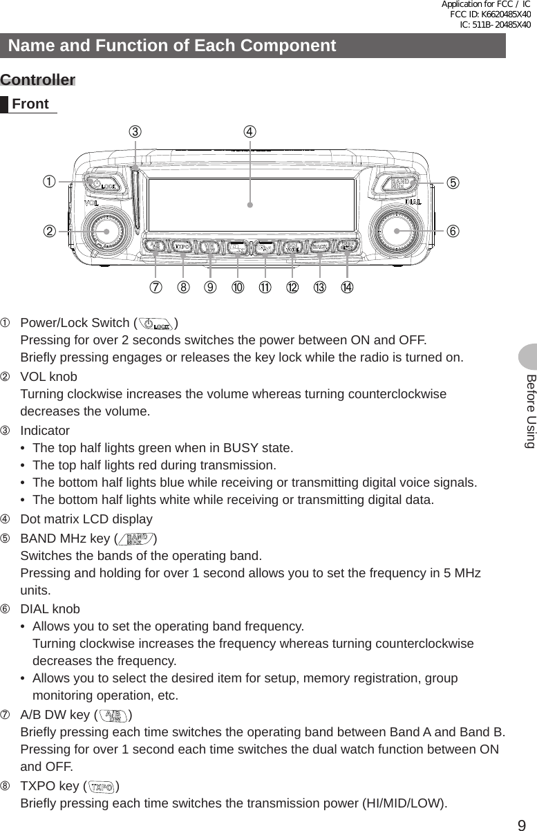
![12Before UsingName and Function of Each ComponentMicrophone (MH-48A6JA)LOCKP3P2P171482059BACD36P4LAMPDTMF MICROPHONEMH-48ABCJKLTUVGHIPQRSDEFMNOWXYZMIC[UP] Frequency is increased by 1 step.[DWN] Frequency is decreased by 1 step.[LOCK] Locks / unlocks the [UP] and [DWN] keys and [P1] to [P4] keys.[LAMP] Turns the lamp on the body of the microphone on/off.[MIC] Speak into here during transmission.[1] to [0] Enters the numbers and letters.[✽] Changes the VFO/Memory operating mode of the operating band.[#] Activates the GM (Group Monitor) functions.[A] Switches the operating band to Band A.[B] Switches the operating band to Band B.[C] Adjusts the squelch level.[D] Switches the display.[P1] Turns off the squelch (T.CALL: European version).[P2] Recalls the receiver home channel.[P3] Changes the communication mode.[P4] Changes the transmit power.[PTT] Press this key to begin the transmit mode.TipPreferred functions can be assigned to buttons [P1] to [P4]. Select using the [CONFIG]→[10MICPROGRAM KEY] in the set-up menu.Application for FCC / IC FCC ID: K6620485X40 IC: 511B-20485X40](https://usermanual.wiki/Yaesu-Musen/20485X40.User-Manual-Part-1/User-Guide-2578115-Page-12.png)
![13Before UsingName and Function of Each ComponentExplanation of the screen➁➂➆➅➄➃➀➀ Icon displayDisplays the Bluetooth, APRS, microSD card and GPS icons when each function is in use.➁ Station location information displayDisplays the partner station location information and your location information. Briefly pressing the key each time switches the information to display.➂ Sub-band frequency displayDisplays the sub-band name (A or B) and sub-band frequency.➃ SQL level display➄ Communication mode displayDisplays the mode name such as analog and digital using abbreviations.While in Auto mode, a bar appears and flashes above the abbreviation display. In Auto mode, the communication mode is automatically set according to the receiving signal.➅ Operating band name/memory channel/transmission powerDisplays the operating band name (A or B) in VFO mode.Displays and the memory channel number in memory mode.Displays for “LO” and for “MID”.➆ Frequency displayDisplays the operating band frequency. ●GPS INFO screenWhen the partner information is displayed, briefly press the key twice to display the GPS INFO screen.The GPS satellite reception status is displayed. ○ appears when the receiving signal is weak whereas ● appears when the receiving signal is strong. Tip From [1 DISPLAY] → [4 GPS INFO], you can select “LOCATION” (location display) or “FREQUENCY” (frequency display).Application for FCC / IC FCC ID: K6620485X40 IC: 511B-20485X40](https://usermanual.wiki/Yaesu-Musen/20485X40.User-Manual-Part-1/User-Guide-2578115-Page-13.png)