Yaesu Musen 20523X50 VHF DIGITAL/ANALOGUE TRANSCEIVER User Manual OM
Yaesu Musen Co., Ltd. VHF DIGITAL/ANALOGUE TRANSCEIVER OM
UserManual.wiki
>
Yaesu Musen
>
20523X50 User Manual
>
User Manual - 1
Contents
1.
User Manual - 1
2.
User Manual 2
3.
User Manual - 2
User Manual - 1
Navigation menu
Upload a User Manual
Namespaces
Wiki Guide
HTML
PDF
Info
Views
User Manual
Discussion / Help
Navigation
![2ContentsFTM-3200DR Operating ManualFTM-3200DR Quick Reference Guide ..................... 3Introduction ............................................................... 4Features of this radio ............................................... 4Accessories & Options ............................................ 5Supplied Accessories .............................................. 5Optional Accessories ............................................... 5Installation ................................................................. 6Connecting the Microphone ..................................... 6Connecting the Antenna .......................................... 6Mobile Installation .................................................... 7Power connection ................................................. 8Base Station Installation .......................................... 9AC Power Supplies ............................................... 9Front Panel Controls & Switches .......................... 10Front Panel ............................................................ 10Microphone Switches ............................................. 12Microphone (MH-48A6JA) ..................................... 12[P1] button (SQL OFF) ........................................ 12[P2] button (HOME) ............................................ 12[P3] button (CD SRCH)....................................... 12[P4] button (WX CH/T.CALL) .............................. 12Rear Panel Connectors .......................................... 13Rear Panel ............................................................. 13Basic Operation ...................................................... 14Turning the Transceiver ON and OFF ................... 14Inputting the call sign ............................................. 14Adjusting the Audio Volume Level ......................... 14Adjusting the Squelch Setting ................................ 14Frequency Navigation ............................................ 15Using the Dial ..................................................... 15Using the MH-48A6JA Microphone..................... 15Channel Step Selection ......................................... 15Selecting the communication mode ....................... 16Transmission ......................................................... 17Adjusting the transmit power .............................. 18Lock Feature .......................................................... 18Advanced Operation .............................................. 19Repeater Operation ............................................... 19Checking the Repeater Uplink (Input) Frequency 19Weather Broadcast Reception ............................... 20Severe Weather Alert Feature ............................ 20CTCSS Operation .................................................. 21DCS Operation ...................................................... 21EPCS (Enhanced Paging & Code Squelch) Operation ............................................................... 22Split Tone Operation .............................................. 22DTMF Operation .................................................... 22Memory Operation .................................................. 23Memory Storage .................................................... 23Split Memory ....................................................... 23Naming a Memory Channel ................................ 23Memory Recall ....................................................... 24Memory Recall from the Microphone’s Keypad .. 24Masking Memories ................................................ 25Un Masking Memory ........................................... 25HOME Channel Memory ....................................... 25Changing the frequency of the home channel .... 25Scanning ................................................................. 26Basic Scanner Operation ....................................... 26Scan Resume Options ........................................ 26Memory Skip Scanning ....................................... 26Preferential Memory Scan .................................. 26Programmable Memory Scan (PMS) .................. 26Priority Channel Scanning (Dual Watch) ............ 26GM Function ............................................................ 27What is the GM (Group Monitor) Function? ........... 27Displaying all the stations using the GM function 27Miscellaneous Settings .......................................... 28Reset Procedure .................................................... 28Microprocessor Resetting ................................... 28Set Mode Resetting ............................................ 28Programming the Key Assignments ...................... 29Keyboard Beeper ................................................... 29Display Brightness ................................................. 29Time-Out-Timer (TOT) ........................................... 29Automatic Power Off (APO) ................................... 29Busy Channel Lock-Out (BCLO) ........................... 29TX Deviation Level ................................................ 29MIC Gain Setting ................................................... 29Packet Operation .................................................... 30Cloning .................................................................... 31Setup (Menu) Mode ................................................ 32Specifications ......................................................... 35Application for FCC / IC FCC ID: K6620523X50 / IC: 511B-20523X50](https://usermanual.wiki/Yaesu-Musen/20523X50.User-Manual-1/User-Guide-2879959-Page-2.png)
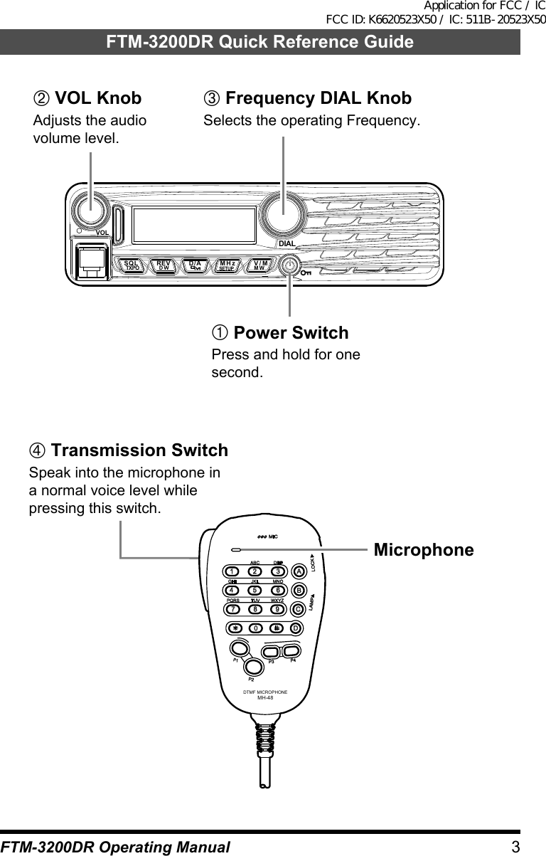
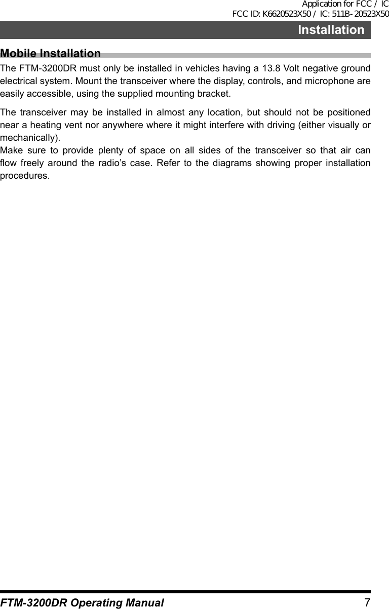
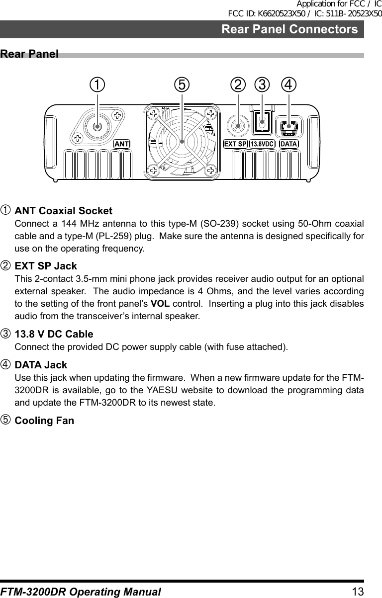
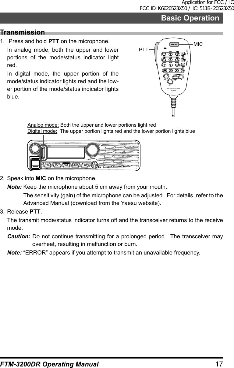
![10 FTM-3200DR Operating ManualFront Panel Controls & SwitchesFront PanelVOLDIALSQLTXPO DW MWSETUPREV D/A V/MMHz VOL knobTurning the knob clockwise increases the volume, whereas turning it counterclockwise decreases the volume. Mode/Status indicatorIndicates the transmission/reception status with a two-color combination on the upper and lower portions of the mode/status indicator.Communication status Upper portion Lower portionReceiving analog audio Green GreenTransmitting analog audio Red RedReceiving digital audio Green BlueTransmitting digital audio Red BlueReceiving digital data Green WhiteTransmitting digital data Red WhiteReceiving signals with unmatchedtone frequency or DCS code Green Blink in BlueDIAL Knob• Allows you to set the operating band frequency. Turning clockwise increases the frequency whereas turning counterclockwise decreases the frequency.• Allows you to select the desired item for setup, memory registration, group monitoring operation, etc.MIC JackConnect the provided microphone cable.[SQL(TXPO)] keyPressing this key briefly and rotating the DIAL sets the squelch level.Press and hold in this key for over 1 second to select the transmission power (HIGH: 65 W / MID: 30 W / LOW: 5 W).Application for FCC / IC FCC ID: K6620523X50 / IC: 511B-20523X50](https://usermanual.wiki/Yaesu-Musen/20523X50.User-Manual-1/User-Guide-2879959-Page-10.png)
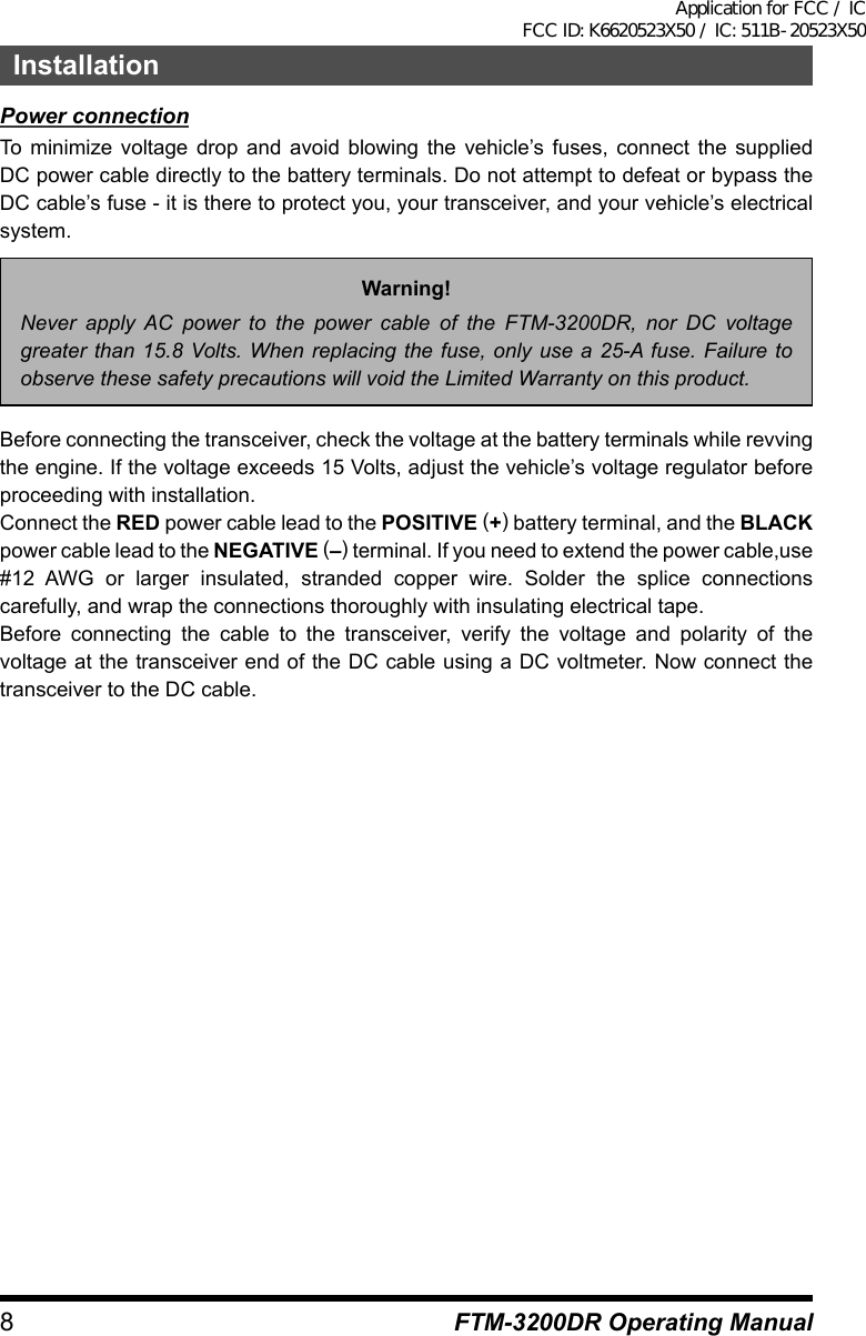
![11Front Panel Controls & SwitchesFTM-3200DR Operating Manual[REV(DW)] keyDuring split-frequency operation, such as through a repeater, this key reverses the transmit and receive frequencies.Press and hold in this key for over 1 second to activate the Dual Watch feature.Note: For details, refer to the Advanced Manual (download from the Yaesu website).[D/A(GM)] keyBriefly pressing each time switches the operating band communication mode.Press and hold in this key for over 1 second to activate the GM (Group Monitor) function.Note: For details on the GM function, see “GM (Group Monitor) Function” on page xx.[MHz(SETUP)] keyThis key allows tuning in 1 MHz steps (the MHz digits will blink on the display).Press and hold in this key for over 1 second to activate the Setup (Menu) Mode.[V/M(MW)] keyBriefly pressing each time switches between VFO mode and memory mode.Press and hold for over 1 second displays the memory registration screen.Power/Lock keyPress and hold in this key for over 1 seconds switches the power between ON and OFF.Briefly pressing the key while the transceiver is turned ON engages or releases the key lock.SpeakerLCD DisplayS and TX Power MeterCommunication modeLock Feature ActiveDTMF Memory ModeSKIP/Preferential Scan ChannelNarrow DeviationLOW/MID TX Power SelectedMemory modeMemory Channel NumberCommunication range indicator of the GM FeatureAMS FunctionGM Feature ActiveFrequency/Message AreaHOME ChannelCTCSS/DCS/EPCS Bell PagingCTCSS(Continuous Tone Coded Squelch System)DCS (Digital Code Squelch)Repeater Shift DirectionApplication for FCC / IC FCC ID: K6620523X50 / IC: 511B-20523X50](https://usermanual.wiki/Yaesu-Musen/20523X50.User-Manual-1/User-Guide-2879959-Page-11.png)
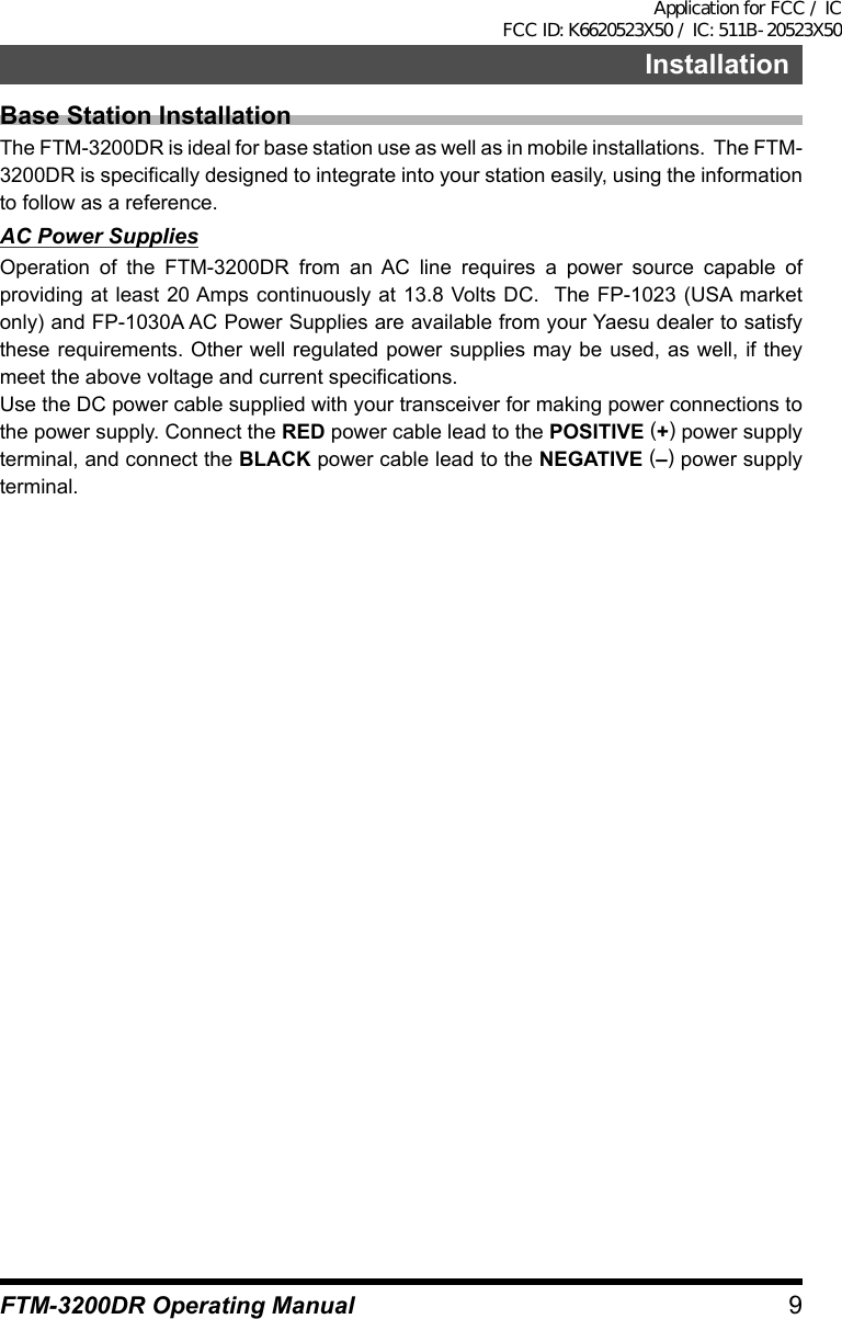
![12 FTM-3200DR Operating ManualMicrophone SwitchesMicrophone (MH-48A6JA) PTT SwitchPress this switch to transmit, and release it to receive. KEY PadThese 16 keys generate DTMF tones during transmission.In the receive mode, these 16 keys can be used for direct frequency entry and/or direct numeric recall of the Memory channels.[P1] / [P2] / [P3] / [P4] keysThese four keys are user programmable, allowing quick access to features used often.The default functions are described below.[P1] button (SQL OFF)Press this button to disable the noise and tone squelch systems.LOCKP3P2P171482059BACD36P4LAMPDTMF MICROPHONEMH-48ABCJKLTUVGHIPQRSDEFMNOWXYZMIC[P2] button (HOME)Press this button to recall the receiver HOME channel.[P3] button (CD SRCH)Press this button to activate the Tone Search feature.[P4] button (WX CH/T.CALL)In the USA version, pressing this button recalls the “Weather” broadcast channel bank.In the EXP version, pressing this button activates T.CALL (1750 Hz) for repeater access.You can reprogram the [P1], [P2], [P3], and [P4] buttons for other functions, if desired.Note: For details, refer to the Advanced Manual (download from the Yaesu website).MICSpeak into this part during transmission.[UP] / [DWN] keysPress (or hold in) either of these buttons to tune (or scan up or down) the operating frequency or through the memory channels. In many ways, these buttons emulate the function of the (rotary) DIAL knob.LOCK switchThis switch locks out the Microphone’s buttons (except for the keypad and PTT switch).LAMP switchThis switch illuminates the Microphone’s keypad.Application for FCC / IC FCC ID: K6620523X50 / IC: 511B-20523X50](https://usermanual.wiki/Yaesu-Musen/20523X50.User-Manual-1/User-Guide-2879959-Page-12.png)
![14 FTM-3200DR Operating ManualBasic OperationTurning the Transceiver ON and OFF1. To turn the transceiver ON, press and hold in the PWR key for 1 second.2. To turn the transceiver OFF, again press and hold in the PWR key for 1 second.VOLDIALSQLTXPO DW MWSETUPREV D/A V/MMHzYou can set the Opening Message to any desired message (up to 8 characters) via Setup Menu Item “OPEN MSG 27” see page xx for details.Inputting the call signA screen requesting input of a call sign appears when turning the transceiver on for the first time, or after resetting the transceiver. The call sign is used to identify the transmitting station when communicating in digital mode.1. Press the [V/M(MW)] key.2. Rotate the DIAL knob to select characters, then press the [V/M(MW)]. By rotating the DIAL knob, you can switch the characters in the following order:“space” à “-” à “/” à “0” to “9” à “A” to “Z”r Up to 10 characters (alphanumeric char-acters including hyphen) can be entered.r “space”, “-”, and “/” are not selectable for the first character.Adjusting the Audio Volume LevelRotate the VOL knob to adjust the receiver volume. Clock-wise rotation increases the audio output level.VOLDIALSQLTXPO DW MWSETUPREV D/A V/MMHzAdjusting the Squelch Setting1. Press the [SQL(TXPO)] key, then rotate the DAIL knob to select the Squelch level.2. Press the [SQL(TXPO)] key again.Note: A special “RF Squelch” feature is pro-vided on this radio. This feature allows you to set the squelch so that only sig-nals exceeding a certain S-meter lev-el will open the squelch. For details, refer to the Advanced Manual (down-load from the Yaesu website).VOLDIALSQLTXPO DW MWSETUPREV D/A V/MMHzApplication for FCC / IC FCC ID: K6620523X50 / IC: 511B-20523X50](https://usermanual.wiki/Yaesu-Musen/20523X50.User-Manual-1/User-Guide-2879959-Page-14.png)
![15Basic OperationFTM-3200DR Operating ManualFrequency NavigationUsing the DialRotating the DIAL knob allows tuning in the pre-programmed steps. Clockwise rotation tunes the frequency upwards, whereas coun-terclockwise rotation tunes the frequency downwards.r Press the [MHz(SETUP)] key momentarily, then rotate the DIAL knob, to change the frequency steps to 1 MHz per step.VOLDIALSQLTXPO DW MWSETUPREV D/A V/MMHzUsing the MH-48A6JA MicrophoneUsing the [UP] and [DWN] key:Pressing [UP] momentarily, tunes the frequen-cy upwards. Whereas pressing [DWN] momen-tarily tunes the frequency in the downwards di-rection.Using the number keys:Use the [0] to [9] number keys to directly input the frequency.There is no “decimal point” key on the MH-48A6J keypad. However, there is a short-cut for frequencies ending in zero:press the [#] key after the last non-zero digit.UPDWNNumber keysExamples: To enter 146.520 MHz, press [1] à [4] à [6] à [5] à [2] à [0] To enter 146.000 MHz, press [1] à [4] à [6] à [#]Channel Step SelectionThe DIAL and microphone [UP]/[DWN] keys frequency tuning step can be changed.Note: See Setup Menu Item “STEP 43” on page xx.Application for FCC / IC FCC ID: K6620523X50 / IC: 511B-20523X50](https://usermanual.wiki/Yaesu-Musen/20523X50.User-Manual-1/User-Guide-2879959-Page-15.png)
![16Basic OperationFTM-3200DR Operating ManualSelecting the communication modeThe FTM-3200DR transceiver is equipped with the AMS (Automatic Mode Select) function which automatically selects from 4 modes of transmission corresponding to the signal being received.The transmit mode is selected according to the received signal so that C4FM digital signals, and analog signals are received and transmitted automatically.Press [D/A(GM)] key to display “ ” (blinks) icon on the screen.Display example when in AMS modeTo operate in fixed communication mode, press [D/A(GM)] key to switch the communication mode.Each time [D/A(GM)] key is pressed, the communication mode changes in the following order:à AMS (“ ” blinks) à V/D (“ ” lights up) à FM (no icon) àCommunication mode Icon Description of modesAMS (Automatic Mode Select) (blinks)Transmission mode is automatically selected from 4 types according to the signal received.The AMS function operation can be changed from the Setup menu setting. See “Setting the transmission mode when using the AMS function (DIG AMS 11)” on page xxx.V/D Mode(Voice/Data simultaneous transmission mode) (light up)Calls are less prone to interruptions due to detection and correction of voice signals during digital voice signal transmission. This is the standard mode for C4FM Digital.Analog FM Mode no iconAnalog communication using FM mode.Effective when the signal is weak and audio is susceptible to interruption in digital mode.Application for FCC / IC FCC ID: K6620523X50 / IC: 511B-20523X50](https://usermanual.wiki/Yaesu-Musen/20523X50.User-Manual-1/User-Guide-2879959-Page-16.png)
![18Basic OperationFTM-3200DR Operating ManualAdjusting the transmit powerWhen communicating with a nearby station, the transmit power level may be lowered to reduce the battery power consumption.1. Press and hold in the [SQL(TXPO)] key for over 1 second.2. Rotate the DIAL to select the transmit pow-er.Note: The default setting: HIGHVOLDIALSQLTXPO DW MWSETUPREV D/A V/MMHzHIGH (65 W) MID (30 W) LOW (5 W)3. Press the [SQL(TXPO)] key to save the new setting and exit to normal operation.Lock FeatureTo activate the locking feature, press the [Power(Lock)] key. The “ ” icon will appear on the LCD.To cancel locking, press the [Power(Lock)] key again.VOLDIALSQLTXPO DW MWSETUPREV D/A V/MMHzTo lock out some or all of the keys, use the Setup Menu Item “LOCK 23” see page xx for details.Application for FCC / IC FCC ID: K6620523X50 / IC: 511B-20523X50](https://usermanual.wiki/Yaesu-Musen/20523X50.User-Manual-1/User-Guide-2879959-Page-18.png)
![19FTM-3200DR Operating ManualAdvanced OperationRepeater OperationThe FTM-3200DR includes the ARS (Automatic Repeater Shift) function which permits communication through repeaters automatically, by simply setting the receiver to the repeater frequency.1. Tune to the repeater frequency.2. Press the PTT to transmit. During transmission, radio waves having an 100.0 Hz* tone signal are emitted on the frequency lower than reception frequency by 5 MHz*. *: Depends on the transceiver version.Note: From the Setup Menu, you can change the repeater setting.RPT ARS 36 à Deactivates the ARS function.RPT FREQ 37 à Allows changing the repeater shift frequency offset.RPT SFT 38 à Allows setting the repeater shift direction.Checking the Repeater Uplink (Input) FrequencyIt often is helpful to be able to check the uplink (input) frequency of a repeater, to see if the calling station is within direct (“Simplex”) range.To do this, just press the [REV(DW)] key. You’ll notice that the display has shifted to the repeater uplink frequency. Press the [REV(DW)] key again to cause operation to revert to normal monitoring of the repeater downlink (output) frequency. While you are listening on the input frequency to the repeater using the [REV(DW)] key, the repeater offset icon will blink.BlinksApplication for FCC / IC FCC ID: K6620523X50 / IC: 511B-20523X50](https://usermanual.wiki/Yaesu-Musen/20523X50.User-Manual-1/User-Guide-2879959-Page-19.png)
![20Advanced OperationFTM-3200DR Operating ManualWeather Broadcast ReceptionThe FTM-3200R includes a unique feature which allows reception of weather broadcasts in the 160 MHz frequency range. Ten standard Weather Broadcast channels are preloaded into a special memory bank.To listen to a Weather Broadcast Channel:1. Press the Microphone’s [P4] button to recall the Weather Broadcast channels.Note: The [P4] key, one of the programma-ble keys, is assigned (default setting) as the “WX Broadcast” one-touch access key. Please note that if you change/assign another function to the [P4] key, one-touch access to the WX channel will be unavailable.2. Turn the DIAL knob to select the desired Weather Broadcast channel.3. If you wish to check the other channels for activity by scanning, just press the Micro-phone’s PTT switch.4. To exit to normal operation, press the [P4] button again. Operation will return to the VFO or Memory channel you were operating on before you began Weather Broadcast op-eration.LOCKP3P2P171482059BACD36P4LAMPDTMF MICROPHONEMH-48ABCJKLTUVGHIPQRSDEFMNOWXYZMICP4 keyPTTCH Frequency CH Frequency1 162.550 MHz 6 162.500 MHz2 162.400 MHz 7 162.525 MHz3 162.475 MHz 8 161.650 MHz4 162.425 MHz 9 161.775 MHz5 162.450 MHz 10 163.275 MHzSevere Weather Alert FeatureIn the event of extreme weather disturbances, such as storms and hurricanes, NOAA (theNational Oceanic and Atmospheric Administration) sends a weather alert accompanied by a 1050 Hz tone and subsequent weather report on one of the NOAA weather channels. You may enable this feature via Setup Menu Item “WX ALERT 50” see page xx for details.Application for FCC / IC FCC ID: K6620523X50 / IC: 511B-20523X50](https://usermanual.wiki/Yaesu-Musen/20523X50.User-Manual-1/User-Guide-2879959-Page-20.png)