Yaesu Musen 20534X20 UHF Amateur Radio with Scanning Receiver User Manual Operating Manual
Yaesu Musen Co., Ltd. UHF Amateur Radio with Scanning Receiver Operating Manual
USERS MANUAL
UHF FM TRANSCEIVER
FT-257
Operating Manual
YAESU MUSEN CO., LTD.
Tennozu Parkside Building
2-5-8 Higashi-Shinagawa, Shinagawa-ku, Tokyo 140-0002 Japan
YAESU USA
6125 Phyllis Drive, Cypress, CA 90630, U.S.A.
YAESU UK
Unit 12, Sun Valley Business Park, Winnall Close
Winchester, Hampshire, SO23 0LB, U.K.
YAESU HK
Unit 2002, 20/F, 9 Chong Yip Street,
Kwun Tong, Kowloon, Hong Kong
FCC ID: K6620534X20 / IC: 511B-20534X20
YAESU MUSEN CO., LTD.

Contents
Scanning ............................................................28
VFO Scanning ...............................................29
Manual VFO Scan .....................................29
Programmed VFO Scan ............................. 29
Memory Scanning ..........................................30
How to Skip (Omit) a Channel
during Memory Scan Operation ................30
Preferential Memory Scan .........................31
Memory Bank Scan ...................................32
Programmable (Band Limit) Memory Scan
(PMS) .............................................................33
“Priority Channel” Scanning
(Dual Watch) ..................................................34
Automatic Lamp Illumination
on Scan Stop ..................................................36
Band Edge Beeper .........................................36
Emergency Channel Operation ......................37
Smart Search Operation ..................................38
ARTS
(Automatic Range Transponder System)
........39
DTMF Operation .............................................42
Miscellaneous Settings .....................................45
Password ........................................................45
Changing the Channel Steps ..........................46
Receive Battery Saver Setup .........................46
TX Battery Saver ...........................................47
Transmitter Time-Out Timer (TOT) ..............47
Busy Channel Lock-Out (BCLO) ..................48
DCS Code Inversion ......................................48
Changing the TX Deviation Level .................49
Reset Procedures ..............................................50
Set Mode ...........................................................51
Specications ....................................................61
General Description ...........................................1
Accessories & Options .......................................2
Controls & Connections ....................................3
Top & Front Panel ...........................................3
LCD .................................................................4
Installation of Accessories .................................5
Antenna Installation .........................................5
Installation of FNB-124LI Battery Pack..........5
Battery Charging ..............................................6
Low Battery Indication ....................................6
Belt Clip Installation ........................................7
Operation ............................................................8
Switching Power On and Off ...........................8
Adjusting the Audio Volume Level .................8
Squelch Adjustment .........................................8
Frequency Navigation ......................................9
Transmission ..................................................10
Advanced Operation ........................................ 11
Keyboard Locking .........................................11
LCD Illumination...........................................12
Disabling the Keypad Beeper ........................12
RF Squelch.....................................................13
Checking the Battery Voltage ........................13
Repeater Operation..........................................14
Repeater Shifts ...............................................14
Automatic Repeater Shift (ARS) ...................14
Manual Repeater Shift Activation .................15
CTCSS/DCS Operation ...................................17
CTCSS Operation ..........................................17
DCS Operation...............................................18
Tone Search Scanning .................................... 19
CTCSS/DCS Bell Operation..........................20
Split Tone Operation ......................................21
Tone Calling (1750 Hz) .................................21
Memory Mode ..................................................22
Memory Storage ............................................22
Storing Independent
Transmit Frequencies (“Odd Split”) ..........22
Memory Recall ..............................................23
HOME Channel Memory ..............................23
Labeling Memories ........................................24
Memory Offset Tuning ..................................25
Deleting Memories ........................................26
Memory Bank Operation ...............................26
Moving Memory Data to the VFO ................27
Memory Only Mode ......................................27
FCC ID: K6620534X20 / IC: 511B-20534X20
YAESU MUSEN CO., LTD.
FT-257 OperaTing Manual 1
General Description
The FT-257 is a compact, high-performance FM hand-held providing up to ve watts of
RF power and wealth of convenient features for the 430 MHz amateur band.
Additional features include a transmit Time-Out Timer (TOT), Automatic Power-Off
(APO), Automatic Repeater Shift (ARS), YAESU’s exclusive ARTS™ (Auto-Range
Transponder System) which “beeps” the user when you move out of communications
range with another ARTS™ equipped station. And an RF squelch circuit allows the
owner to set the squelch to open at a programmable setting of the S-Meter, thus reduc-
ing guesswork in setting the squelch threshold.
We appreciate your purchase of the FT-257, and encourage you to read this manual
thoroughly, so as to learn about the many exciting features of your exciting new YAESU
hand-held transceiver!
FCC ID: K6620534X20 / IC: 511B-20534X20
YAESU MUSEN CO., LTD.

FT-257 OperaTing Manual2
Supplied Accessories
FNB-124LI 7.4 V Rechargeable Lithium-Ion Battery Pack
YHA-76 Antenna
SAD-11B AC Wall Charger (100 - 120 VAC, Typ-A plug)
CD-57 Charger Cradle
Belt Clip
Operating Manual
Warranty Card
Available Options
FNB-124LI 7.4 V Rechargeable Lithium-Ion Battery Pack
SAD-11B/C/U AC Wall Charger
CD-57 Charger Cradle
CN-3 BNC-to-SMA Adapter
: “
B” sufx is for use with 100-120 VAC, “C” and “U” sufx is for use with 230-240
VAC.
Availability of accessories may vary. Some accessories are supplied as standard per lo-
cal requirements, while others may be unavailable in some regions. This product is de-
signed to perform optimally when used with genuine YAESU accessories. YAESU shall
not be liable for any damage to this product and/or accidents such as re, leakage or
explosion of a battery pack, etc., caused by the malfunction of non- YAESU accessories.
Consult your YAESU dealer for details regarding these and any newly-available options.
Connection of any non-YAESU-approved accessory, should it cause damage, may void
the Limited Warranty on this apparatus.
Accessories & Options
FCC ID: K6620534X20 / IC: 511B-20534X20
YAESU MUSEN CO., LTD.
FT-257 OperaTing Manual 3
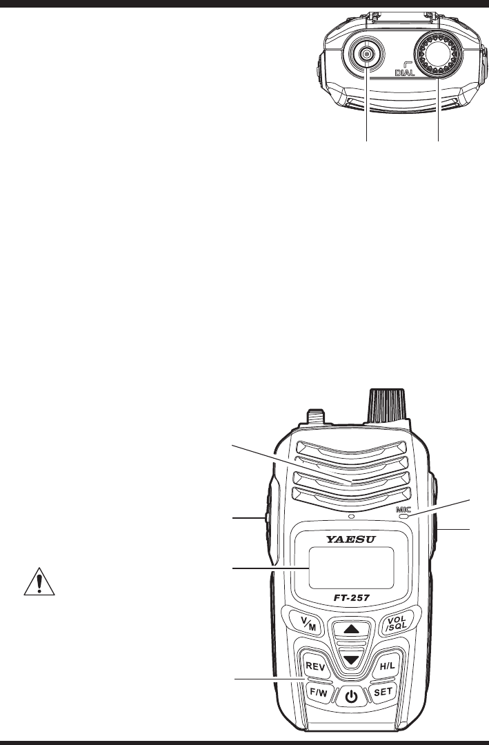
Antenna Jack
Connect the supplied rubber ex antenna (or an-
other antenna presenting a 50-Ohm impedance)
here.
DIAL Knob
The main tuning Dial is used to set the operating
frequency, and is also used for menu selections
and other adjustments.
Speaker
The internal speaker is located here.
PTT (Push To Talk) Switch
Press this switch to transmit, and release it (to receive) after your transmission is
completed.
LCD (Liquid Crystal Display)
The display shows the current operating conditions, as described on the next page.
Keypad
These 9 keys select many of most important operating features on the FT-257.
MIC
The internal microphone is lo-
cated here.
EXT DC Jack
This coaxial DC jack allows
connection to an external DC
power source (5-10V DC). The
center pin of this jack is the
Positive (+) connection.
Do not allow the FT-
257 to become sub-
merged in water while the
rubber cap over the EXT DC
jack is removed.
Controls & Connectors
FCC ID: K6620534X20 / IC: 511B-20534X20
YAESU MUSEN CO., LTD.
FT-257 OperaTing Manual4
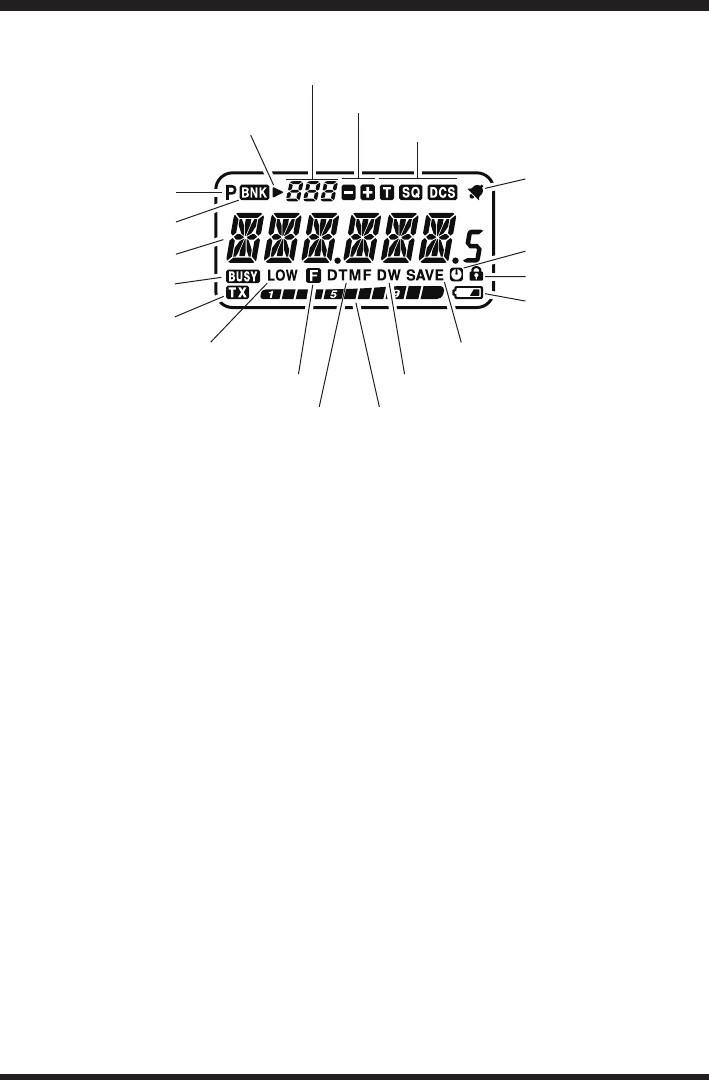
Controls & Connectors (LCD)
Operating Frequency
BUSY Indicator
TX Indicator
Memory Channel Number
S- & PO Meter
Skip Memory Channel or Pref-
erential Memory Channel
Repeater Shift Direction
CTCSS/DSC Operation
Key Lock Active
Bell Alarm Active
Battery Saver Active
Dual Watch Active
Priority Channel
Battery Indicator
Memory Bank Active
Low TX Power Selected
Automatic Power-Off Active
DTMF Autodial Active
Secondary Keypad Active
FCC ID: K6620534X20 / IC: 511B-20534X20
YAESU MUSEN CO., LTD.
FT-257 OperaTing Manual 5
Antenna Installation
The supplied antenna provides good results over the entire frequency range of the trans-
ceiver. However, for enhanced reception on certain non-Amateur frequencies, you may
wish to connect an antenna designed specically for that fre-
quency range, as the supplied antenna is necessarily a com-
promise outside the Amateur band, and cannot be expected to
provide high performance at all frequencies.
To install the supplied antenna, hold the bottom end of the an-
tenna, then screw it onto the mating connector on the transceiv-
er until it is snug. Do not over-tighten by use of extreme force.
Notes:
Never transmit without having an antenna connected.
When installing the supplied antenna, never hold the upper part of the antenna while
screwing it onto the mating connector on the transceiver.
If using an external antenna for transmission, ensure that the SWR presented to the
transceiver is 1.5:1 or lower, to avoid excessive feedline loss.
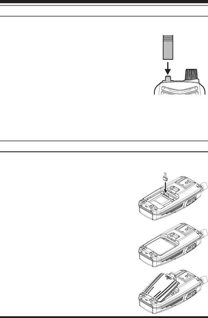
Installation of FNB-124LI Battery Pack
The FNB-124LI is a high performance Li-ion battery providing high capacity in a
compact package.
Recharging can be provided while the pack is installed inside the FT-257.
Installation of the battery is easy and quick:
Open the Battery Cover Latch on the Battery Cover,
then remove the Battery Cover from the radio while
pulling the top side of the Battery Cover.
Connect the 3-pin connector from the Battery pack
to the battery jack on the transceiver.
Install the FNB-124LI Battery Pack into the radio.
Install the Battery Cover by carefully aligning the
two tabs on the bottom of the cover with the slots
on the radio, then gently press the top side of the
Battery Cover. Conrm that a Rubber Gasket of the
Battery Cover is installed correctly.
Close the Battery Cover Latch until it locks in place
with a “Click”.
Caution:
To insure the FT-257 will not have a problem with
water intrusion, make sure the battery cover is properly
installed and the battery latch is closed.
Installation of Accessories
FCC ID: K6620534X20 / IC: 511B-20534X20
YAESU MUSEN CO., LTD.
FT-257 OperaTing Manual6
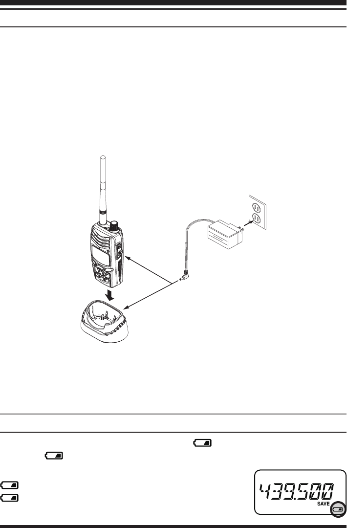
Battery Charging
If the battery has never been used, or its charge is depleted, it may be charged by con-
necting the SAD-11B Overnight Battery Charger, as shown in the illustration, to the
EXT DC jack. If only 12 ~ 16 Volt DC power is available, the optional E-DC-5B DC
Cable (with its cigarette lighter plug) or E-DC-6 DC Cable (plug and wire only) may
also be used for charging the battery.
The display will blink “CHG.ING”, while the battery is being charged. When charging is
nished, the “CHG.ING” disappears in the display.
A fully-discharged pack will be charged completely in 5 hours. Disconnect the SAD-
11B from the EXT DC jack and the AC line outlet.
Installation of Accessories
Important Note
The
SAD-11B is not designed to power the transceiver for operation (reception or
transmission).
Please be advised that the SAD-11B may contribute noise to TV and radio reception
in the immediate vicinity, so we do not recommend its use adjacent to such devices.
Low Battery Indication
When the battery charge is almost depleted, a “ ” icon will appear on the display.
When the “ ” icon appears, it is recommended that you charge the battery soon.
No Icon: Enough Battery Power
: Lower Battery Power
(Blinking): Prepare to charge (or replace) the Battery
FCC ID: K6620534X20 / IC: 511B-20534X20
YAESU MUSEN CO., LTD.
FT-257 OperaTing Manual 7
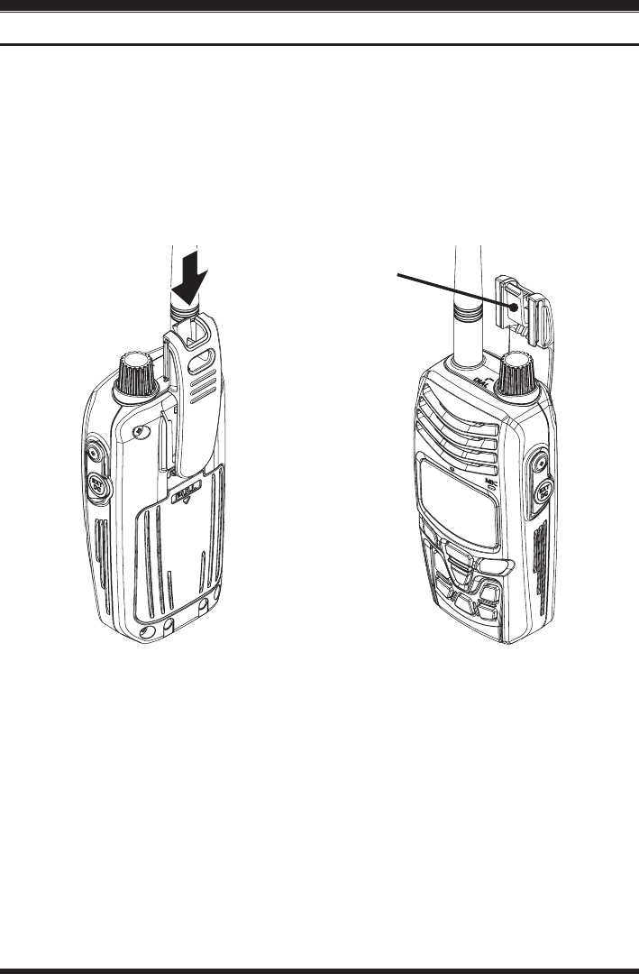
Belt Clip Installation / Removal
Installation of Accessories
To install the Belt Clip:
Align the Belt Clip to the groove
above the Battery compartment, then
press the Belt Clip downward until it
locks in place with a “Click”.
To remove the Belt Clip:
Press the Belt Clip tab away from the
transceiver to unlock the Belt Clip,
then slide the Belt Clip up-ward to re-
move it.
Belt Clip Tab
FCC ID: K6620534X20 / IC: 511B-20534X20
YAESU MUSEN CO., LTD.

FT-257 OperaTing Manual8
Switching Power ON and OFF
Be sure the Battery Pack is installed, and that the battery is fully charged. Connect
the antenna to the top panel ANTENNA jack.
Press and hold the [POWER] key for two seconds to turn on the radio The current
DC supply voltage will be indicated on the display for 2 seconds. After this 2 second
interval, the display will resume its normal indication of the operating frequency.
To turn the radio off, press and hold the [POWER] key for two seconds.
Adjusting the Audio Volume Level
Press the [VOL/SQL] key to enter the receiver audio adjustment mode. When “VOL” is
displayed, rotate the DIAL knob or press the [p]/[q] key until the noise or audio from
the speaker is at a comfortable level.
Squelch Adjustment
Press the [VOL/SQL] key twice to enter the squelch level adjustment mode. When “LVL”
is displayed, rotate the DIAL knob or press the [p]/[q] key to set the Squelch so that
the backgroundnoise is just silenced. This state is known as the “Squelch Threshold”.
1) A special “RF Squelch” feature is provided on this radio. This feature allows you
to set the squelch so that only signals exceeding a certain S-meter level will open
the squelch. See page 13 for details.
2) If you’re operating in an area of high RF pollution, you may need to consider “Tone
Squelch” operation using the built-in CTCSS Decoder. This feature will keep your
radio quiet until a call is received from a station sending a carrier which contains
a matching (subaudible) CTCSS tone. Or, if your friends have radios equipped
with DCS (Digital Coded Squelch) like your FT-257 has, try using that mode for
silent monitoring of busy channels.
Operation
FCC ID: K6620534X20 / IC: 511B-20534X20
YAESU MUSEN CO., LTD.

FT-257 OperaTing Manual 9
Operation
Frequency Navigation
The FT-257 will initially be operating in the “VFO” mode, a channelized system which
allows free tuning throughout the operating band.
Two basic frequency navigation methods are available on the FT-257:
1) Tuning Dial
Rotation of the DIAL allows tuning in the pre-programmed steps established for the
operating band. Clockwise rotation of the DIAL causes the FT-257 to be tuned toward a
higher frequency, while counter-clockwise rotation will lower the operating frequency.
If you press the [F/W] key momentarily, then rotate the DIAL, frequency steps of 1 MHz
will be selected. This feature is extremely useful for making rapid frequency excursions
over the wide tuning range of the FT-257.
2) Scanning
Press and hold in either the [p] or [q] key for one second to initiate upward or down-
ward scanning, respectively (Manual VFO Scan).
If you wish to reverse the direction of the scan (i.e. toward a lower frequency, instead
of a higher frequency), just rotate the DIAL one click in the counter-clockwise direc-
tion while the FT-257 is scanning. The scanning direction will be reversed. To revert to
scanning toward a higher frequency once more, rotate the DIAL one click clockwise.
The scanner will stop when it receives a signal strong enough to break through the
Squelch threshold. The FT-257 will then hold on that frequency according to the setting
of the “RESUME” mode (Set Mode Item 31: RESUME). Press the PTT switch momen-
tarily to cancel the scanning. This only stops the scan; it does not cause transmission to
occur. See page 29 for details regarding Scan Operation.
FCC ID: K6620534X20 / IC: 511B-20534X20
YAESU MUSEN CO., LTD.
FT-257 OperaTing Manual10
Transmission
Once you have set up an appropriate frequency inside the 144 MHz Amateur band on
which the FT-257 can transmit, you’re ready to go on the air! These are the most basic
steps; more advanced aspects of transmitter operation will be discussed later.
To transmit, press the PTT switch, and speak into the front panel microphone (located
in the lower right-hand corner of the speaker grille) in a normal voice level. The “TX”
indicator will appears on the LCD during transmission.
To return to the receive mode, release the PTT switch.
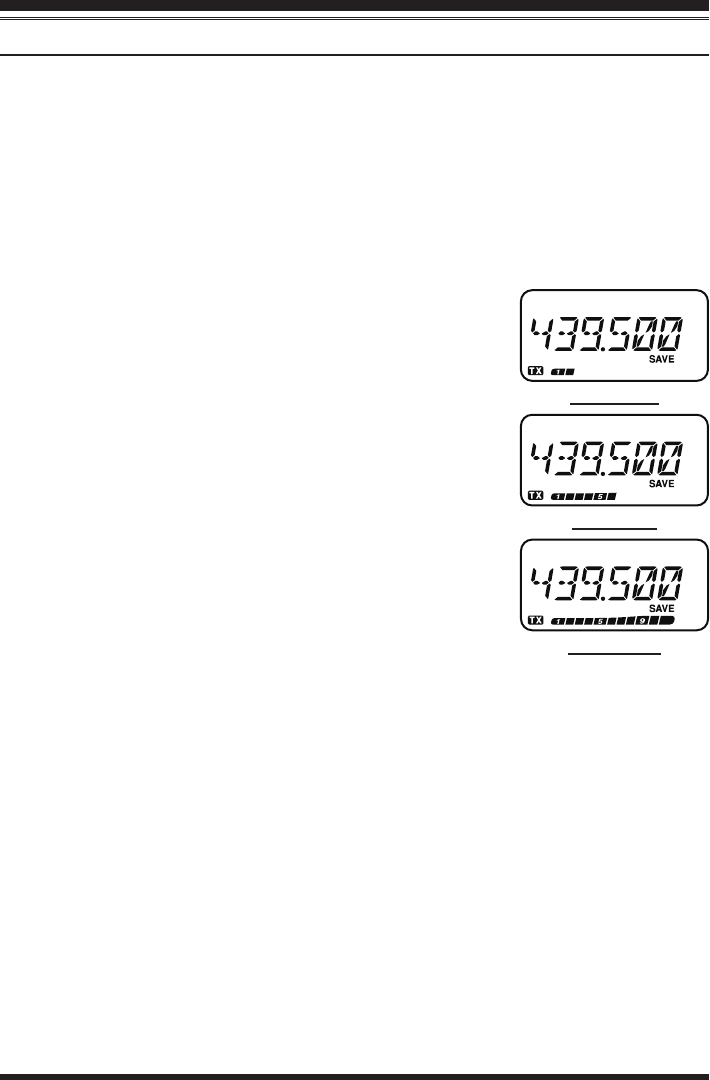
During transmission, the relative power level will be indicated on the bar graph at
the bottom of the LCD; full scale deection conrms “High
Power” operation, while deection of two bars indicates
“Low Power” operation. Six bars indicate “Medium Pow-
er” operation. Additionally, the “LOW” icon will appear
at the display while operating on the “Low Power” and
“Medium Power” settings.
1) If you’re just talking to friends in the immediate area,
you’ll get much longer battery life by switching to Low
Power operation, described in the next chapter. And
don’t forget: always have an antenna connected when
you transmit.
2) Transmission is possible only on the 144 MHz amateur
band.
Changing the Transmitter Power Level
To change the power level:
Press the [H/L] key. The LCD shows the current power output level.
Rotate the DIAL knob or press the [p]/[q] key to select the desired power output
level. Available selections are “HIGH” (5 W), “MID” (2 W), and “LOW” (0.5 W).
When you have made your choice, press the PTT switch to save the new setting and
return to normal operation.
1) The FT-257 is smart! When you store memories, you can store the power output
settings separately in each memory, so you don’t waste battery power when using
very close-in repeaters!
2) When you are operating on the “Low” or “Medium” power setting, you can press
the [F/W] key, then press the PTT switch, to cause the FT-257 to transmit (tem-
porarily) on High power. After one transmission, the power level will revert to the
previously-selected (“Low” or “Medium” power) setting.
Operation
“Low” Power
“Mid” Power
“HigH” Power
FCC ID: K6620534X20 / IC: 511B-20534X20
YAESU MUSEN CO., LTD.
FT-257 OperaTing Manual 11
Advanced Operation
Now that you’re mastered the basics of FT-257 operation, let’s learn more about some
of the really neat features.
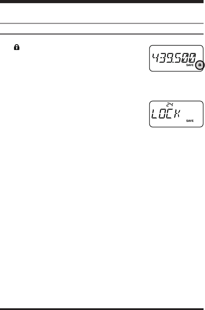
Keyboard Locking
To activate the locking feature, prees the [F/W] key, then press the [POWER] key.
The “ ” icon will appear on the LCD. To cancel locking
prees the [F/W] key, then press the [POWER] key.
In order to prevent accidental frequency change or inadver-
tent transmission, various aspects of the FT-257’s DIAL and
keypad may be locked out. You may change the lockout combinations.
To lock out some or all of the keys:
1. Press the [SET] key to enter the Set mode.
2. Rotate the DIAL knob or press the [p]/[q] key to select
Set Mode Item 24: LOCK.
3. Press the [F/W] key momentarily to enable adjustment of
this Item.
4. Rotate the DIAL knob or press the [p]/[q] key to the desired locking scheme as
listed below:
LK KEY: Just the front panel keypad is locked out
LKDIAL: Just the top panel DIAL is locked out
LK K+D: Both the keypad and DIAL are locked out (factory default)
LK PTT: The
PTT switch is locked out (TX not possible)
LK P+K: Both the PTT switch and keypad are locked out
LK P+D: Both the PTT switch and DIAL are locked out
LK ALL: All of the above are locked out
5. When you have made your selection, press the PTT switch to save the new setting
and return to normal operation.
FCC ID: K6620534X20 / IC: 511B-20534X20
YAESU MUSEN CO., LTD.
FT-257 OperaTing Manual12
LCD Illumination
Your FT-257 includes a reddish illumination lamp which aids in nighttime operation.
The reddish illumination yields clear viewing of the display in a dark environment, with
minimal degradation of your night vision.
Three options for activating the lamp are provided:
KEY Mode: Illuminates the LCD lamp for ve seconds when you rotate the DIAL
knob or press the keypad or any switch (except PTT switch). This is
the factory-programmed default setting.
CONT Mode: Illuminates the LCD lamp continuously.
OFF Mode: Disables the LCD lamp.
Here is the procedure for setting up the Lamp operating mode:
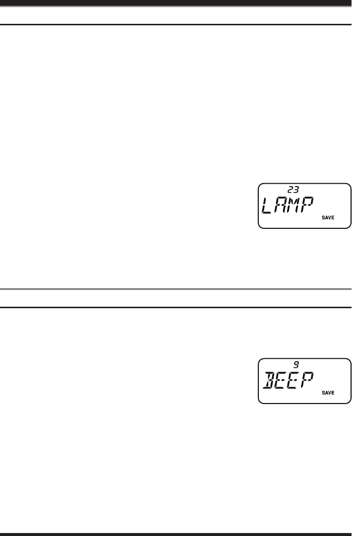
1. Press the [SET] key to enter the Set mode.
2. Rotate the DIAL knob or press the [p]/[q] key to select
Set Mode Item 23: LAMP.
3. Press the [F/W] key momentarily to enable adjustment of
this Item.
4. Rotate the DIAL knob or press the [p]/[q] key to select one of the three modes de-
scribed above.
5. When you have made your choice, press the PTT switch to save the new setting and
return to normal operation.
Disabling the Keypad Beeper
A keypad beeper provides useful audible feedback whenever a keypad is pressed.
If you want to turn the beep off:
1. Press the [SET] key to enter the Set mode.
2. Rotate the DIAL knob or press the [p]/[q] key to select
Set Mode Item 9: BEEP.
3. Press the [F/W] key momentarily to enable adjustment of
this Item.
4. Rotate the DIAL knob or press the [p]/[q] key to change the setting to “OFF.”
5. Press the PTT switch to save the new setting and return to normal operation.
6. To turn the beep back on again, select “KEY” or “KEY+SC (factory default)” in step
4 above.
KEY: The beeper sounds when you press the keypad.
KEY+SC: The beeper sounds when you press the keypad, or when the scanner
stops.
Advanced Operation
FCC ID: K6620534X20 / IC: 511B-20534X20
YAESU MUSEN CO., LTD.
FT-257 OperaTing Manual 13
Advanced Operation
RF Squelch
A special RF Squelch feature is provided on this radio. This feature allows you to set the
squelch so that only signals exceeding a certain S-meter level will open the squelch.
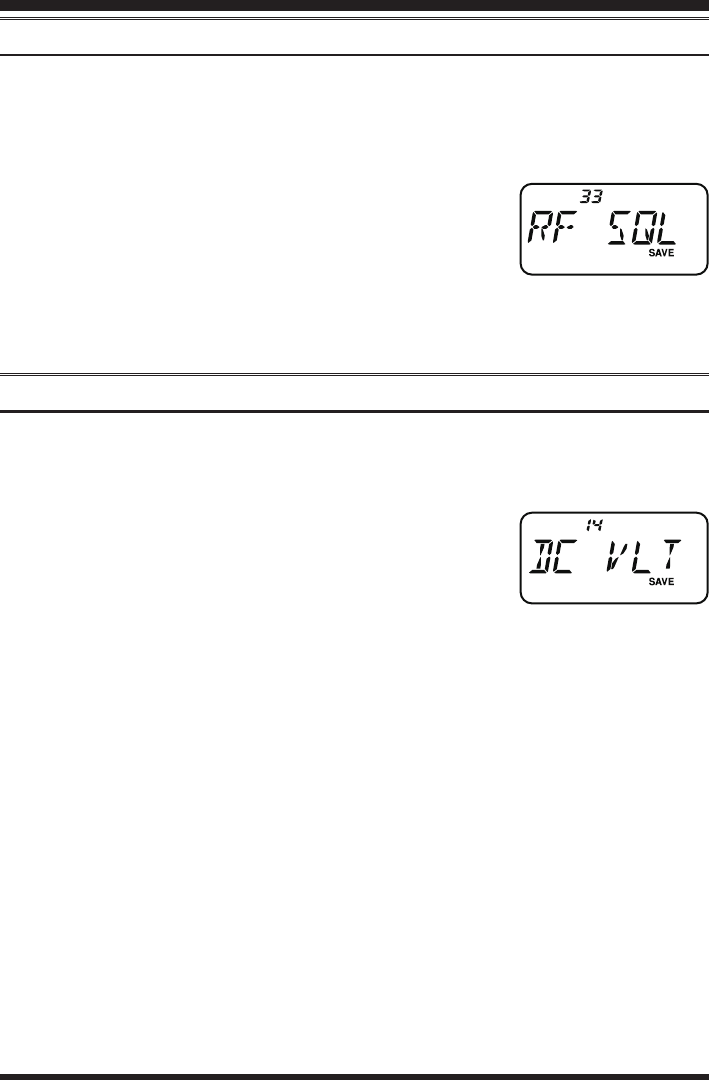
To set up the RF squelch circuit for operation, use the following procedure:
1. Press the [SET] key to enter the Set mode.
2. Rotate the DIAL knob or press the [p]/[q] key to select
Set Mode Item 33: RF SQL.
3. Press the [F/W] key momentarily to enable adjustment of
this Item.
4. Rotate the DIAL knob or press the [p]/[q] key to select the desired signal strength
level for the squelch threshold (S-1, S-2, S-3, S-4, S-5, S-7, S-FULL, or OFF).
5. Press the PTT switch to save the new setting and return to normal operation.
Checking the Battery Voltage
The FT-257’s microprocessor includes programming which will measure the current
battery voltage.
1. Press the [SET] key to enter the Set mode.
2. Rotate the DIAL knob or press the [p]/[q] key to to se-
lect Set Mode Item 14: DC VLT.
3. Press the [F/W] key momentarily to display the current
DC voltage being supplied.
4. Press the [F/W] key, followed by the PTT switch to return to normal operation.
FCC ID: K6620534X20 / IC: 511B-20534X20
YAESU MUSEN CO., LTD.
FT-257 OperaTing Manual14
Repeater Operation
Repeater stations, usually located on mountaintops or other high locations, provide a
dramatic extension of the communication range for low-powered hand-held or mobile
transceivers. The FT-257 includes a number of features which make repeater operation
simple and enjoyable.
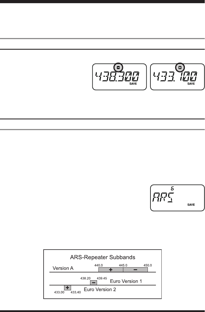
Repeater Shifts
The FT-257 has been congured, at the factory, with the repeater shift set to 600 kHz.
Depending on the part of the band
in which you are operating, the re-
peater shift may be either downward
(–) or upward (+), and one of these
icons will appear at the top of the
LCD when repeater shifts have been
enabled.
Automatic Repeater Shift (ARS)
The FT-257 provides a convenient Automatic Repeater Shift feature, which causes the
appropriate repeater shift to be applied automatically whenever you tune into the desig-
nated repeater sub-bands in your country. These sub-bands are shown below.
If the ARS feature does not appear to be working, you may have accidentally disabled it.
To re-enable ARS:
1. Press the [SET] key to enter the Set mode.
2. Rotate the DIAL knob or press the [p]/[q] key to select
Set Mode Item 6: ARS.
3. Press the [F/W] key momentarily to enable adjustment of
this Item.
4. Rotate the DIAL knob or press the [p]/[q] key to select “ARS. ON”.
5. When you have made your selection, press the PTT switch to save the new setting
and return to normal operation.
FCC ID: K6620534X20 / IC: 511B-20534X20
YAESU MUSEN CO., LTD.
FT-257 OperaTing Manual 15
Repeater Operation
Manual Repeater Shift Activation
If the ARS feature has been disabled, or if you need to set a repeater shift direction other
than that established by the ARS, you may set the direction of the repeater shift manually.
To do this:
1. Press the [SET] key to enter the Set mode.
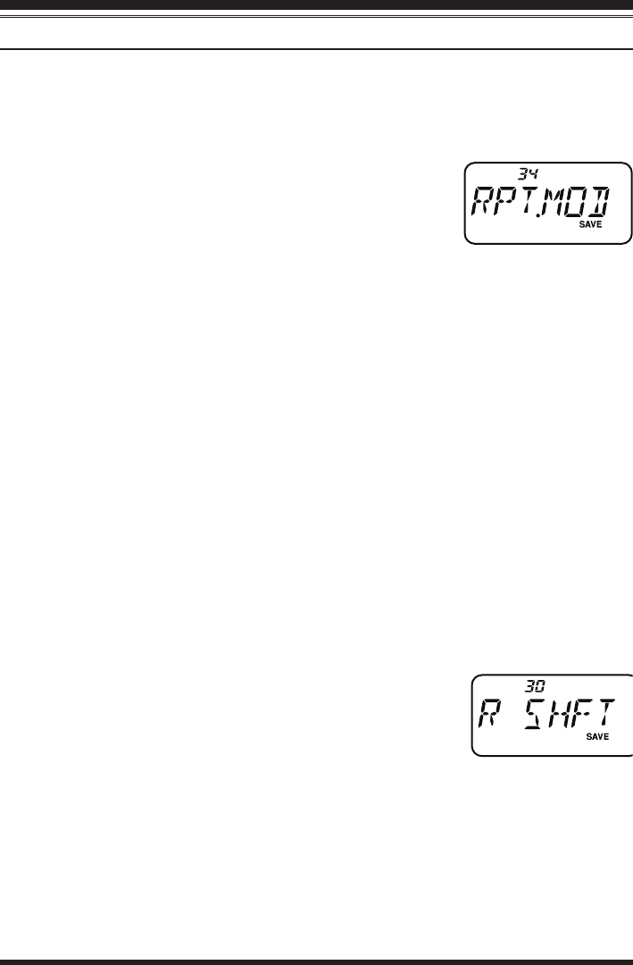
2. Rotate the DIAL knob or press the [p]/[q] key to select
Set Mode Item 34: RPT.MOD.
3. Press the [F/W] key momentarily to enable adjustment of
this Item.
4. Rotate the DIAL knob or press the [p]/[q] key to select the desired shift among
“RPT.–”, “RPT.+”, and “RPT.OFF.”
5. When you have made your selection, press the PTT switch to save the new setting
and return to normal operation.
If you make a change in the shift direction, but still have Automatic Repeater Shift
still engaged (see previous section), when you change frequency (by rotating the DIAL
knob, for example) the ARS will over-ride your manual setting of the shift direction.
Turn ARS off if you do not wish this to happen.
If you make a change in the repeater shift on a memory channel that you already stored,
the radio will consider this a “temporary” change unless you store the memory once
more, this time with the desired repeater shift engaged.
Changing the Default Repeater Shifts
If you travel to a different region, you may need to change the default repeater shift so
as to ensure compatibility with local operating requirements.
To do this, follow the procedure below:
1. Press the [SET] key to enter the Set mode.
2. Rotate the DIAL knob or press the [p]/[q] key to select
Set Mode Item 30: R SHIFT.
3. Press the [F/W] key momentarily to enable adjustment of
this Item.
4. Rotate the DIAL knob or press the [p]/[q] key to select the new repeater shift mag-
nitude.
5. When you have made your selection, press the PTT switch to save the new setting
and return to normal operation.
If you just have one “odd” split that you need to program, don’t change the “default”
repeated shifts using this Set Mode Item. Enter the transmit and receive frequencies
separately, as shown on page 22.
FCC ID: K6620534X20 / IC: 511B-20534X20
YAESU MUSEN CO., LTD.

FT-257 OperaTing Manual16
Checking the Repeater Uplink (Input) Frequency
It often is helpful to be able to check the uplink (input) frequency of a repeater, to see if
the calling station is within direct (“Simplex”) range.
To do this, just press the [REV] key. You’ll notice that the display has shifted to the
repeater uplink frequency. Press the [REV] key again to cause operation to revert to
normal monitoring of the repeater downlink (output) frequency. While you are listening
on the input frequency to the repeater using the [REV] key, the repeater offset icon will
blink.
The conguration of this key may be set either to “REV” (for checking the input fre-
quency of a repeater), or “HOME” (for instant switching to the “Home” channel for
the band you are operating on). To change the conguration of this key, use Set Mode
Item 32: REV/HM. See page 59.
Repeater Operation
Manual Repeater Shift Activation
FCC ID: K6620534X20 / IC: 511B-20534X20
YAESU MUSEN CO., LTD.
FT-257 OperaTing Manual 17
CTCSS/DCS Operation
CTCSS Operation
Many repeater systems require that a very-low-frequency audio tone be superimposed
on your FM carrier in order to activate the repeater. This helps prevent false activation
of the repeater by radar or spurious signals from other transmitters. This tone system,
called “CTCSS” (Continuous Tone Coded Squelch System), is included in your FT-257,
and is very easy to activate.
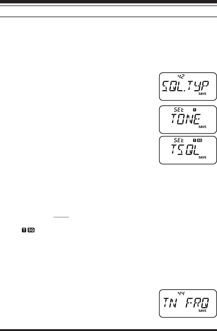
1. Press the [SET] key to enter the Set mode.
2. Rotate the DIAL knob or press the [p]/[q] key to select
Set Mode Item 42: SQL.TYP.
3. Press the [F/W] key momentarily to enable adjustment of
this Item.
4. Rotate the DIAL knob or press the [p]/[q] key so that
“TONE” indication appears on the display; this activates
the CTCSS Encoder, for access to repeaters requiring a
CTCSS tone.
5. Rotation of the DIAL knob one more “click” or press
the [p]/[q] key one more “press” in step “4” above will
cause the “TSQL” notation to appear. When “TSQL” is
displayed, this means that the Tone SQuelch system is ac-
tive, which mutes your FT-257’s receiver until it receives a call from another radio
sending out a matching CTCSS tone. This can help keep your radio quiet until a spe-
cic call is received, which may be helpful while operating in congested areas of the
band.
1) You may notice a “REV TN” indication on the display while you rotate the
DIAL knob in this step; this means that the Reverse Tone Squelch system is
active, which mutes your FT-257’s receiver (instead of opening the squelch)
when it receives a call from the radio sending a matched CTCSS tone. The
“ ” icon will blink on the display when the Reverse Tone Squelch system is
activated.
2) You may notice the “DCS” indications on the display while you rotate the
DIAL knob still more. We’ll discuss the Digital Code Squelch system (for
“DCS”) later.
6. When you have made your selection of the CTCSS tone mode, press the PTT switch
to save the new setting.
7. Press the [SET] key to enter the Set mode.
8. Rotate the DIAL knob or press the [p]/[q] key to select
Set Mode Item 44: TN FRQ.
9. Press the [F/W] key momentarily to enable adjustment of
this Item.
FCC ID: K6620534X20 / IC: 511B-20534X20
YAESU MUSEN CO., LTD.
FT-257 OperaTing Manual18
10. Rotate the DIAL knob until the display indicates the Tone Frequency you need to be
using (ask the repeater owner/operator if you don’t know the tone frequency).
11. When you have made your selection,
press the [F/W] key, then press the PTT
switch to save the new settings and
exit to normal operation. This is differ-
ent than the usual method of restoring
normal operation, and it applies only to
the configuration of the CTCSS/DCS
frequencies.
Your repeater may or may not re-transmit a CTCSS tone - some systems just use
CTCSS to control access to the repeater, but don’t pass it along when transmitting. If
the S-Meter deects, but the FT-257 is not passing audio, repeat steps “1” through “4”
above, but rotate the DIAL so that “TSQ” disappears - this will allow you to hear all
trafc on the channel being utilized.
DCS Operation
Another form of tone access control is Digital Code Squelch, or DCS. It is a newer,
more advanced tone system which generally provides more immunity from false pag-
ing than does CTCSS. The DCS Encoder/Decoder is built into your FT-257, and op-
eration is very similar to that just described for CTCSS. Your repeater system may be
congured for DCS; if not, DCS is frequently quite useful in Simplex operation if your
friend(s) use transceivers equipped with this advanced feature.
Just as in CTCSS operation, DCS requires that you set the Tone Mode to DCS and
that you select a tone code.
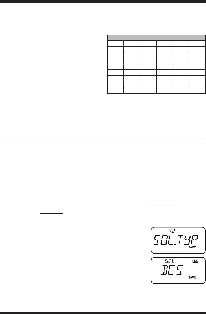
1. Press the [SET] key to enter the Set mode.
2. Rotate the DIAL knob or press the [p]/[q] key to select
Set Mode Item 42: SQL.TYP.
3. Press the [F/W] key momentarily to enable adjustment of
this Item.
4. Rotate the DIAL knob or press the [p]/[q] key so that
“DCS” indication appears on the display; this activates the
DCS Encoder/Decoder.
5. Press the PTT switch to save the new setting.
6. Press the [SET] key to enter the Set mode.
7. Rotate the DIAL knob or press the [p]/[q] key to select Set Mode Item 15: DCS.
COD.
CTCSS Operation
CTCSS/DCS Operation
CTCSS TONE FREQUENCY (Hz)
67.0 69.3 71.9 74.4 77.0 79.7
82.5 85.4 88.5 91.5 94.8 97.4
100.0 103.5 107.2 110.9 114.8 118.8
123.0 127.3 131.8 136.5 141.3 146.2
151.4 156.7 159.8 162.2 165.5 167.9
171.3 173.8 177.3 179.9 183.5 186.2
189.9 192.8 196.6 199.5 203.5 206.5
210.7 218.1 225.7 229.1 233.6 241.8
250.3 254.1 – – – –
FCC ID: K6620534X20 / IC: 511B-20534X20
YAESU MUSEN CO., LTD.
FT-257 OperaTing Manual 19
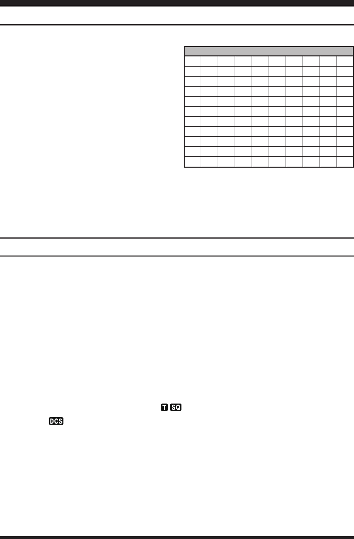
DCS CODE
023 025 026 031 032 036 043 047 051 053
054 065 071 072 073 074 114 115 116 122
125 131 132 134 143 145 152 155 156 162
165 172 174 205 212 223 225 226 243 244
245 246 251 252 255 261 263 265 266 271
274 306 311 315 325 331 332 343 346 351
356 364 365 371 411 412 413 423 431 432
445 446 452 454 455 462 464 465 466 503
506 516 523 526 532 546 565 606 612 624
627 631 632 654 662 664 703 712 723 731
732 734 743 754 – – – – – –
CTCSS/DCS Operation
8. Press the [F/W] key momentarily to enable adjustment of this Item.
9. Rotate the DIAL knob to select the
desired DCS Code (a three-digit num-
ber). Ask the repeater owner/operator if
you don’t know DCS Code; if you are
working simplex, just set up the DCS
Code to be the same as that used by
your friend(s).
10. When you have made your selection,
press the [F/W] key, then press the PTT
switch to save the new settings and exit
to normal operation.
Remember that the DCS is an Encode/Decode system, so your receiver will remain
muted until a matching DCS code is received on an incoming transmission. Switch
the DCS off when you’re just tuning around the band!
Tone Search Scanning
In operating situations where you don’t know the CTCSS or DCS tone being used by
another station or stations, you can command the radio to listen to the incoming signal
and scan in search of the tone being used. Two things must be remembered in this re-
gard:
You must be sure that your repeater uses the same tone type (CTCSS vs. DCS).
Some repeaters do not pass the CTCSS tone; you may have to listen to the station(s)
transmitting on the repeater uplink (input) frequency in order to allow Tone Search
Scanning to work.
To scan for the tone in use:
1. Set the radio up for either CTCSS or DCS Decoder operation (see the previous dis-
cussions). In the case of CTCSS, “ ” will appear on the display; in the case of
DCS, “ ” will appear on the display.
2. Press the [SET] key to enter the Set mode.
3. Rotate the DIAL knob or press the [p]/[q] key to select Set Mode Item 44: TN
FRQ or 15: DCS.COD.
4. Press the [F/W] key, then press and hold in the [p] or [q] key for one second to
start scanning for the incoming CTCSS or DCS tone/code.
5. When the radio detects the correct tone or code, it will halt on that tone/code, and
audio will be allowed to pass. Press the [F/W] key to lock in that tone/code, then
press the [F/W] key again to exit to normal operation.
DCS Operation
FCC ID: K6620534X20 / IC: 511B-20534X20
YAESU MUSEN CO., LTD.
FT-257 OperaTing Manual20
If the Tone Scan feature does not detect a tone or code, it will continue to scan inde-
nitely. When this happens, it may be that the other station is not sending any tone. You
can press the PTT switch to halt the scan at any time.
Tone Scanning works either in the VFO or Memory modes.
CTCSS/DCS Bell Operation
During CTCSS Decode or DCS operation, you may set up the FT-257 such that a ring-
ing “bell” sound alerts you to the fact that a call is coming in. Here is the procedure for
activating the CTCSS/DCS Bell:
1. Set the transceiver up for CTCSS Decode (“Tone Squelch”) or DCS operation, as
described previously.
2. Adjust the operating frequency to the desired channel.
3. Press the [SET] key to enter the Set mode.
4. Rotate the DIAL knob or press the [p]/[q] key to select
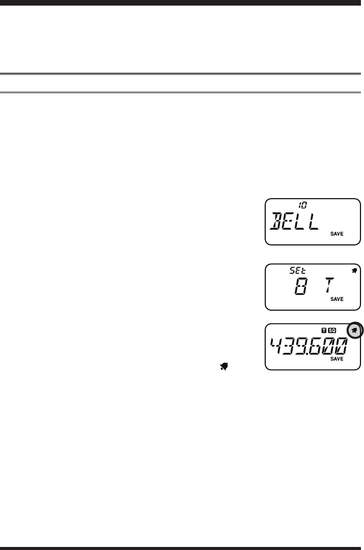
Set Mode Item 10: BELL.
5. Press the [F/W] key momentarily to enable adjustment of
this Item.
6. Rotate the DIAL knob or press the [p]/[q] key to set the desired number of rings of
the Bell. The available choices are “1 T,” “3 T,” “5 T,”
or “8 T” rings, CONT (continuous ringing), or OFF.
7. Press the PTT switch momentarily to save the new setting
and exit to normal operation.
When you are called by a station whose transceiver is sending
a CTCSS tone or DCS code which matches that set into your
Decoder, the Bell will ring in accordance with this program-
ming. When the CTCSS/DCS Bell is activated, the “ ” icon
will appear at the upper right corner on the LCD.
CTCSS/DCS Operation
FCC ID: K6620534X20 / IC: 511B-20534X20
YAESU MUSEN CO., LTD.
FT-257 OperaTing Manual 21
Split Tone Operation
The FT-257 can be operated in a Split Tone conguration via the Set mode.
1. Press the [SET] key to enter the Set mode.
2. Rotate the DIAL knob or press the [p]/[q] key to select
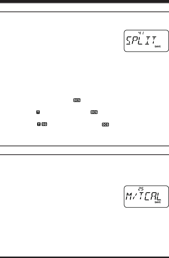
Set Mode Item 41: SPLIT.
3. Press the [F/W] key momentarily to enable adjustment of
this Item.
4. Rotate the DIAL knob or press the [p]/[q] key to select ON (to enable the Split
Tone feature).
5.
Press the PTT switch momentarily to save the new setting and exit to normal operation.
When the Split Tone feature is activated, you can see the following additional param-
eters following the “DCS” parameter (while selecting the tone mode by Set Mode Item
42: SQL.TYP):
D: DCS Encode only (the “ ” icon will appear during operation)
T DCS: Encodes a CTCSS Tone and Decodes a DCS code
(the “ ” icon will blink and the “ ” icon will appear during operation)
D TSQL: Encodes a DCS code and Decodes a CTCSS Tone
(the “ ” icon will appear and the “ ” icon will blink during opera-
tion)
Select the desired operating mode from the selections shown above.
Tone Calling (1750 Hz)
If the repeaters in your country require a 1750-Hz burst tone for access (typically in
Europe), you can set the [VOL/SQL] key to serve as a “Tone Call” switch instead. To
change the conguration of this switch, we again use the Set Mode to help us.
1. Press the [SET] key to enter the Set mode.
2. Rotate the DIAL knob or press the [p]/[q] key to select
Set Mode Item 25: M/T-CAL.
3. Press the [F/W] key momentarily to enable adjustment of
this Item.
4. Rotate the DIAL knob or press the [p]/[q] key to select “T-CALL” on the display.
5. Press the PTT switch to save the new setting and exit to normal operation.
To access a repeater, press and hold in the [VOL/SQL] key for the amount of time speci-
ed by the repeater owner/operator. The transmitter will automatically be activated, and
a 1750-Hz audio tone will be superimposed on the carrier. Once access to the repeater
has been gained, you may release the [VOL/SQL] key for activating the transmitter
thereafter.
CTCSS/DCS Operation
FCC ID: K6620534X20 / IC: 511B-20534X20
YAESU MUSEN CO., LTD.

FT-257 OperaTing Manual22
Memory Mode
The FT-257 provides a wide variety of memory system resources. These include:
200 “Standard” memory channels, numbered “1” through “200.”
A “Home” channel, providing storage and quick recall of one prime frequency.
10 sets of band-edge memories, also known as “Programmable Memory Scan” chan-
nels, labeled “L1/U1” through “L10/U10.”
10 Memory Banks, labeled “BANK 1” through “BANK10.” Each Memory Bank
can be assigned up to 200 channels from the “standard” memory channels.
10 “Weather Broadcast” Channels.
Memory Storage
1. Select the desired frequency, while operating in the VFO mode. Be sure to set up
any desired CTCSS or DCS tones, as well as any desired repeater offset, now. The
power level may also be set at this time, if you wish to store it.
2. Press and hold in the [F/W] key for one second.
3. Within ten seconds of releasing the [F/W] key, you need to make a decision regard-
ing channel storage. The microprocessor will automatically select the next-available
“free” channel (a memory register on which no data has been stored), so you may
not wish to make any change; if this is the case, proceed to step 4. If you wish to se-
lect a different channel number into which to store the data, rotate the DIAL knob or
press the [p]/[q] key to select the desired memory channel.
4. Press the [F/W] key once more to store the frequency into memory.
5. You still will be operating in the “VFO” mode, so you may now enter other frequen-
cies, and store them into additional memory locations, by repeating the above pro-
cess.
Storing Independent Transmit Frequencies (“Odd Splits”)
All memories can store an independent transmit frequency, for operation on repeaters
with non-standard shift. To do this:
1. Store the receive frequency using the method already described under MEMORY
STORAGE (it doesn’t matter if a repeater offset is active).
2. Tune to the desired transmit frequency, then press and hold in the [F/W] key for one
second.
3. Within ten seconds of releasing the [F/W] key, rotate the DIAL knob or press the [p]/
[q] key to select the same memory channel number as used in step “1” above.
4. Press and hold in the PTT switch. Then while holding the PTT switch in, momen-
tarily press the [F/W] key once more. (This does not key the transmitter).
Whenever you recall a memory which contains independently-stored transmit and re-
ceive frequencies, the “ ” indication will appear in the display.
FCC ID: K6620534X20 / IC: 511B-20534X20
YAESU MUSEN CO., LTD.

FT-257 OperaTing Manual 23
Memory Mode
Memory Recall
1. While operating in the VFO mode, press the [V/M] key to
enter the Memory mode.
2. Rotate the DIAL knob or press the [p]/[q] key to select
the desired channel.
3. To return to the VFO mode, press the [V/M] key.
HOME Channel Memory
A special one-touch “HOME” channel is available, to allow quick recall of a favorite
operating frequency.
Home Channel storage is simple to accomplish:
1. Change the setting of Set Mode Item 32: REV/HM from “REV” to “HOME,” if it is
not already set to this option (see page 59).
2. Select the desired frequency, while operating in the VFO mode. Be sure to set up
any desired CTCSS or DCS tones, as well as any desired repeater offset. The power
level may also be set at this time, if you wish to store it.
3. Press and hold in the [F/W] key for one second.
4. While the memory channel number is blinking, just press the [REV] key. The fre-
quency and other data (if any) will now be stored in the
special HOME channel register.
5. To recall the HOME channel, press the [REV] key mo-
mentarily while operating either in the VFO or MR mode.
FCC ID: K6620534X20 / IC: 511B-20534X20
YAESU MUSEN CO., LTD.
FT-257 OperaTing Manual24
Memory Mode
Labeling Memories
You may wish to append an alpha-numeric “Tag” (label) to a memory or memories, to
aid in recollection of the channel’s use (such as a club name, etc.). This is easily accom-
plished using the Set Mode.
1. Recall the memory channel on which you wish to append
a label.
2. Press the [SET] key to enter the Set mode.
3. Rotate the DIAL knob or press the [p]/[q] key to select
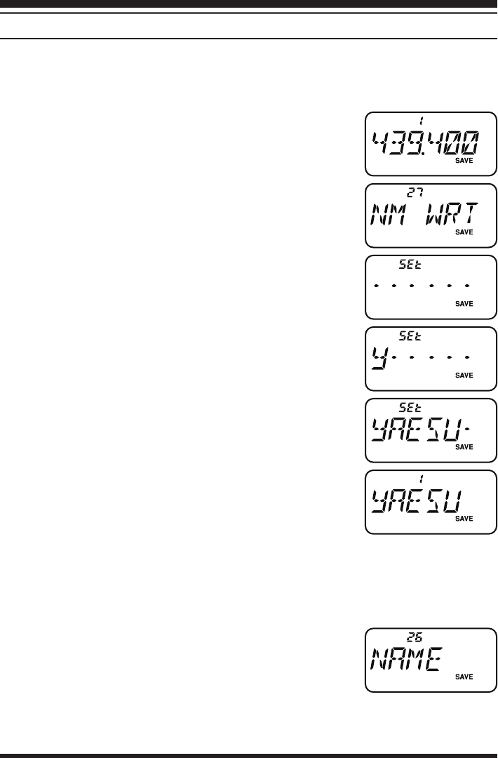
Set Mode Item 27: NM WRT.
4. Press the [F/W] key momentarily to display the previously
stored label (if any).
5. Press the [F/W] key to clear any previous label.
6. Rotate the DIAL knob to select the rst digit of the desired
label.
7. Press the [F/W] key to move to the next character.
8. If you make a mistake, press the [q] key to back-space
the cursor, then re-enter the correct letter, number, or sym-
bol.
9. Repeat steps 5 through 7 to program the remaining letters,
numbers, or symbols of the desired label. A total of six
characters may be used in the creation of a label.
10. When you have programmed a label which is under 6 char-
acters, press and hold in the [F/W] key for one second to
confirm the label (if the label is exactly 6 characters in
length, you do not need to press and hold in [F/W] key).
11. When you have completed the creation of the label, press
the PTT switch to save the label and return to the memory
recall mode.
To enable the alpha-numeric Tag (and disable the frequency display):
1. Set the FT-257 to the “MR” (Memory Recall) mode, and recall the memory channel
on which you wish to enable the alpha-numeric Tag.
2. Press the [SET] key to enter the Set mode.
3. Rotate the DIAL knob or press the [p]/[q] key to select
Set Mode Item 26: NAME.
4. Press the [F/W] key momentarily to enable adjustment of
this Item.
5. Rotate the DIAL knob or press the [p]/[q] key to set this to “ALPHA” (enabling
the alpha-numeric “Tag” display).
FCC ID: K6620534X20 / IC: 511B-20534X20
YAESU MUSEN CO., LTD.

FT-257 OperaTing Manual 25
6. To display the frequency again, just repeat the above procedure.
7. When you have made your selection, press the PTT switch to save the setting and
exit to normal operation.
To display the frequency again, just repeat the above procedure, rotating the DIAL knob
or press the [p]/[q] key to select “FREQ” in step 5 above.
This procedure is not applied to all memory channels at once (just the channel on
which you currently are operating).
Memory Offset Tuning
Once you have recalled a particular memory channel, you may easily tune off that chan-
nel, as though you were in the “VFO” mode.
1. With the FT-257 in the “MR” (Memory Recall) mode, select the desired memory
channel.
2. Press and hold the [REV] key for one second to activate the “Memory Tuning” fea-
ture. The Memory Channel number will be replaced by
“tun.” And if you have an alpha-numeric Tag displayed
on the memory channel, the display will automatically
revert to display of the operating frequency, so you can
navigate without having to enter the Menu to change the display conguration.
3. Rotate the DIAL knob, as desired, to tune to a new frequency. The synthesizer steps
selected for VFO operation will be the steps used during Memory Tuning.
4. If you wish to return to the original memory frequency, just press the [V/M] key mo-
mentarily. The display will revert to display of the alpha-numeric Tag (if any) that
may have originally appeared on the LCD.
5. If you wish to store a new frequency set during Memory Tuning, just press and hold
in the [F/W] key for one second, per normal memory storage procedure. The micro-
processor will automatically set itself to the next-available clear memory location,
and you then press [F/W] again to lock in the new frequency.
1) If you want to replace the original memory contents with those of the new frequen-
cy, be sure to rotate the DIAL knob to the original memory channel number!
2) Any required CTCSS/DCS changes, or repeater offset modications, must be done
before storing the data into the new (or original) memory channel location.
Memory Mode
FCC ID: K6620534X20 / IC: 511B-20534X20
YAESU MUSEN CO., LTD.
FT-257 OperaTing Manual26
Memory Mode
Deleting Memories
You may delete any of the memories (except for Memory Channel “1” and the Home
Channel). The procedure for deleting a channel is quite simple.
1. Press the [V/M] key, if needed, to enter the MR mode.
2. Press and hold in the [F/W] key for one second, then rotate the DIAL knob or press
the [p]/[q] key to select the memory channel to be deleted.
3. Press the [SET] key momentarily. The display will revert to memory channel #1.
The previously-selected memory will be deleted.
Important Notice! Once deleted, the channel data cannot be recovered!
Memory Bank Operation
The large number of memories available in the FT-257 could be difficult to utilize
without some means of organizing them. Fortunately, the FT-257 includes provision for
dividing the memories into as many as ten Memory Groups, so you can categorize the
memories in a manner convenient to you.
Assigning Memories to a Memory Bank
1. Recall the memory channel to be assigned to a Memory
Bank.
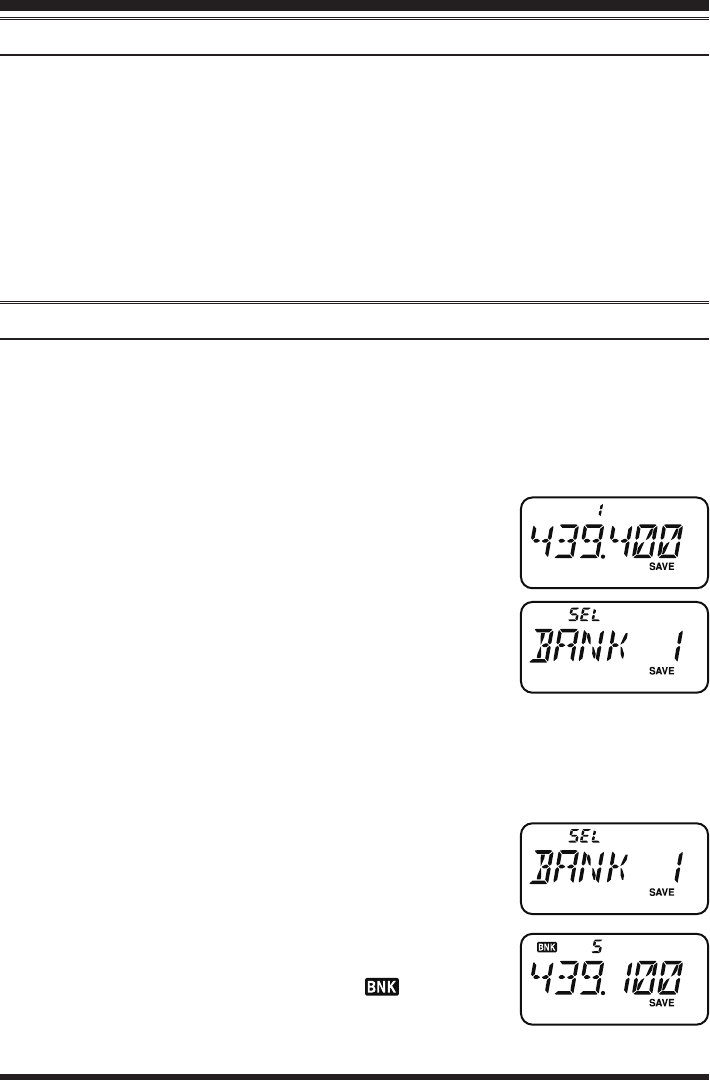
2. Press and hold in the [V/M] key for one second, then ro-
tate the DIAL knob or press the [p]/[q] key to select the
Memory Bank number you want as the Memory Bank for
this channel (“BANK 1” ~ “BANK10”).
3. Press and hold in the [F/W] key for one second to copy
the memory channel data into the Memory Bank.
1) You may assign one memory channel into multiple Memory Banks.
2)
The PMS memory channels (L1/U1 through L10/U10) may not be assigned to a Memory Bank.
Memory Bank Recall
1. Press the [V/M] key, if needed, to enter the Memory Recall mode.
2. Press and hold in the [V/M] key, then rotate the DIAL
knob or press the [p]/[q] key to select the desired Mem-
ory Bank (“BANK 1” through “BANK10”).
3. Press the [V/M] key momentarily; now, as you rotate the
DIAL knob or press the [p]/[q] key to select memories,
you will observe that you can only select memory chan-
nels in the current memory bank. The “ ” indication
will appear at the left side of the frequency display while
operating within a Memory Bank.
FCC ID: K6620534X20 / IC: 511B-20534X20
YAESU MUSEN CO., LTD.
FT-257 OperaTing Manual 27
4. To change to another Memory Bank, press and hold in the [V/M] key, rotate the
DIAL knob or press the [p]/[q] key to select the new Memory Bank, then press the
[V/M] key momentarily.
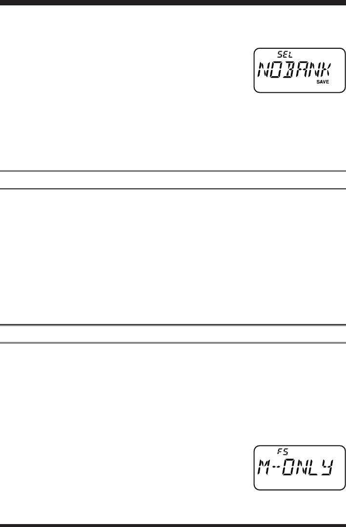
5. To exit from Memory Bank operation, select “NOBANK”
in step 4 above. You are now in the “standard” Memory
Recall mode, without utilization of the Memory Banks.
The memories stored in the various Banks will remain in
those banks, however; you do not need to store them again.
Removing Memories from a Memory Bank
1. Recall the memory channel to be removed from a Memory Bank.
2. Press and hold in the [V/M] key for one second, then press and hold in the [F/W] key
to remove the memory channel data from the Memory Bank.
Moving Memory Data to the VFO
Data stored on memory channels can easily be moved to the last selected VFO, if you
like.
1. Select the memory channel containing the frequency data to be moved to the VFO.
2. Press and hold the [V/M] key to activate the “Memory Tune” feature temporarily,
then press and hold in the [V/M] key for one second. The data will now have been
copied to the last selected VFO, although the original memory contents will remain
intact on the previously-stored channel.
If a Split Frequency Memory channel was transferred, the TX frequency will be ig-
nored (you will be set up for Simplex operation on the Receive frequency).
Memory Only Mode
Once memory channel programming has been completed, you may place the radio in a
“Memory Only” mode, whereby VFO operation is impossible. This may be particularly
useful during public-service events, where a number of operators may be using the radio
for rst time, and ultimate simplicity of channel selection is desired.
To place the radio into the Memory Only mode:
1. Turn the radio off.
2. Press and hold in the [V/M] key while turning the radio on.
3. Rotate the DIAL knob to select the “F5 M-ONLY” option,
then press the [SET] key.
To return to normal operation, repeat the above power-on pro-
cedure.
Memory Mode
FCC ID: K6620534X20 / IC: 511B-20534X20
YAESU MUSEN CO., LTD.

FT-257 OperaTing Manual28
The FT-257 allows you to scan just the memory channels, the entire operating band,
or a portion of that band. It will halt on signals encountered, so you can talk to the
station(s) on that frequency, if you like.
Scanning operation is basically the same in each of the above modes. Before you begin,
take a moment to select the way in which you would like the scanner to resume scan-
ning after it halts on a signal.
Setting the Scan-Resume Technique
Three options for the Scan-Resume mode are available:
BUSY: In this mode, the scanner will halt on a signal it encounters. Two seconds after
the carrier has dropped because the other station(s) ceased transmission, the
scanner will resume. In the case of constant-carrier signals like Weather Station
broadcasts, the scanner will likely remain on this frequency indenitely.
HOLD: In this mode, the scanner will halt on a signal it encounters. It will not restart
automatically; you must manually re-initiate scanning if you wish to resume.
TIME: In this mode, the scanner will halt on a signal it encounters, and will hold there
for ve seconds. If you do not take action to disable the scanner within that time
period, the scanner will resume even if the stations are still active.
To set the Scan-Resume mode:
1. Press the [SET] key to enter the Set mode.
2. Rotate the DIAL knob or press the [p]/[q] key to select
Set Mode Item 31: RESUME.
3. Press the [F/W] key momentarily to enable adjustment of
this Item.
4. Rotate the DIAL knob or press the [p]/[q] key to select the desired scan-resume
mode.
5. When you have made your selection, press the PTT switch to save the new setting
and exit to normal operation.
The default condition for this Set Mode Item is “TIME”.
Scanning
Setting tHe SqueLcH LeveL during Active ScAnning oPerAtion
The FT-257 allows adjustment of the Squelch level “on the y” while you are scanning.
1. While the scanner is engaged, press the [VOL/SQL] key twice (the current squelch
level (e.g. “LVL 1”) will appear in ne print above the frequency display).
2. Rotate the DIAL knob or press the [p]/[q] key to select the desired Squelch
level.
3. Press the PTT switch momentarily to save the new setting and exit to normal
operation. In this case, pressing the PTT switch this one time will not causing
scanning to stop.
FCC ID: K6620534X20 / IC: 511B-20534X20
YAESU MUSEN CO., LTD.
FT-257 OperaTing Manual 29
Scanning
VFO Scanning
The FT-257 provides two VFO scanning functions: “Manual VFO Scanning” and “Pro-
grammed VFO Scanning.”
Manual VFO Scan
1. Select the VFO mode by pressing the [V/M] key, if necessary.
2. Press and hold in either the [p] or [q] key for one second to initiate upward or
downward scanning, respectively.
3. If and when the scanner encounters a signal strong enough to open the squelch, the
scanner will halt temporarily; the decimal point of the frequency display will blink
during this “Pause” condition.
4. The scanner will then resume according to the Scan-Resume mode selected in the
previous section.
5. To cancel scanning, press the PTT switch or [V/M] key.
Programmed VFO Scan
1. Select the VFO mode by pressing the [V/M] key, if necessary.
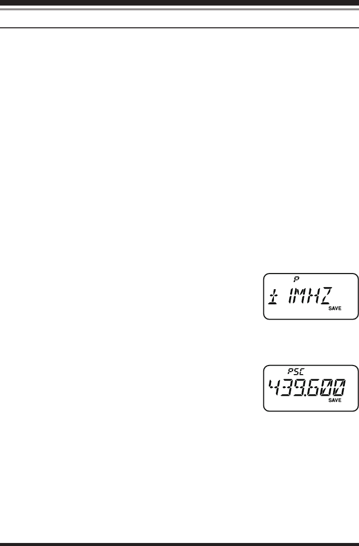
2. Press and hold the [REV] key, then rotate the DIAL knob or press the [p]/[q] key to
select the bandwidth for the Programmed VFO scanner. Available selections are ±1
MHz, ±2 MHz, ±5 MHz, PMS-x, and ALL.
±1 MHz, ±2 MHz, ±5 MHz:
The scanner will sweep frequencies within the
selected bandwidth.
PMS-x: The scanner will sweep frequencies within the
currently-selected PMS frequency pair. See page 34 for details.
ALL: The scanner will sweep all frequencies.
3.
Press the PTT switch momentarily to save the new setting and exit to normal operation.
4. Press and hold in the [V/M] key for one second to start
scanning.
5. If and when the scanner encounters a signal strong enough
to open the squelch, the scanner will halt temporarily; the
decimal point of the frequency display will blink during this “Pause” condition.
6. The scanner will then resume according to the Scan-Resume mode selected in the
previous section.
7. To cancel scanning, press the PTT switch.
When you start the Programmed VFO Scanner, the FT-257 will be changing fre-
quency in the upward direction. If you want to change direction of the scan while it is
underway, rotate the DIAL knob one click in the opposite direction (in this case, one
click counter-clockwise). You’ll see the scanner turn around and change frequency
downward!
FCC ID: K6620534X20 / IC: 511B-20534X20
YAESU MUSEN CO., LTD.

FT-257 OperaTing Manual30
Memory Scanning
Memory scanning is similarly easy to initiate:
1. Select the Memory mode by pressing the [V/M] key, if necessary.
2. Press and hold in either the [p] or [q] key for one second to initiate upward or
downward scanning, respectively.
3. If and when the scanner encounters a signal strong enough to open the squelch, the
scanner will halt temporarily; the decimal point of the frequency display will blink
during this “Pause” condition.
4. The scanner will then resume according to the Scan-Resume mode selected in the
previous section.
5. To cancel scanning, press the PTT switch.
How to Skip (Omit) a Channel during Memory Scan Operation
As mentioned previously, some continuous-carrier stations like a Weather Broadcast sta-
tion will seriously impede scanner operation if you are using the “Carrier Drop” Scan-
Resume mode, as the incoming signal will not pause long enough for the transceiver to
resume scanning. Such channels may be “Skipped” during scanning, if you like:
1. Recall the Memory Channel to be skipped during scanning.
2. Press the [SET] key to enter the Set mode.
3. Rotate the DIAL knob or press the [p]/[q] key to select Set Mode Item 40: SKIP.
4. Press the [F/W] key momentarily enter the “Skip” channel-selection mode.
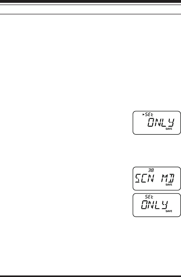
5. Rotate the DIAL knob or press the [p]/[q] key so as to
select “SKIP”. The current Memory Channel will now be
ignored during scanning. The “ONLY” selection is used
for “Preferential Memory Scan,” described in the next
section.
6. When you have made your selection, press the PTT switch to save the setting and
exit to normal operation.
When you recall the “skipped” memory channel manually, a
small “” icon will appear at the left of the memory channel
number, indicating it is to be ignored during scanning.
To re-institute a channel into the scanning loop, select “OFF”
in step 5 above (the “Skipped” channel will, of course, still be accessible via manual
channel selection methods using the DIAL knob in the MR mode, whether or not it is
locked out of the scanning loop).
Scanning
FCC ID: K6620534X20 / IC: 511B-20534X20
YAESU MUSEN CO., LTD.
FT-257 OperaTing Manual 31
Scanning
Preferential Memory Scan
The FT-257 also allows you to set up a “Preferential Scan List” of channels which you
can “ag” within the memory system. These channels are designated by a blinking “”
icon when you have selected them, one by one, for the Preferential Scan List.
When you initiate memory scanning, beginning on a channel with the blinking “” icon
appended, only those channels bearing the blinking “” icon will be scanned. If you
initiate scanning on a channel which does not have the blinking “” icon appended, you
will scan all channels including those with the blinking “” icon appended.
Here is the procedure for setting up and using the Preferential Scan List:
1. Recall the Memory Channel which you wish to add to the Preferential Scan List.
2. Press the [SET] key to enter the Set mode.
3. Rotate the DIAL knob or press the [p]/[q] key to select Set Mode Item 40: SKIP.
4. Press the [F/W] key momentarily enter the “Skip” channel-selection mode.
5. Rotate the DIAL knob or press the [p]/[q] key so as to
select “ONLY”.
6. When you have made your selection, press the PTT
switch to save the setting and exit to normal operation.
7. To remove a channel from the Preferential Scan List, just repeat the above proce-
dure, rotating the DIAL knob to select “OFF” in step 5 above.
To initiate Preferential Memory Scan:
1. Press the [SET] key to enter the Set mode.
2. Rotate the DIAL knob or press the [p]/[q] key to select
Set Mode Item 38: SCN MD.
3. Press the [F/W] key momentarily to enable adjustment of
this Set Mode Item.
4. Rotate the DIAL knob or press the [p]/[q] key so as to
select “ONLY”.
5. Press the PTT switch to save the setting and exit to nor-
mal operation.
6. Now, press and hold in either the [p] or [q] key for one second to initiate the Pref-
erential Memory Scan. Only the channels which have the blinking “” icon append-
ed to the channel number will be scanned.
7. To cancel the Preferential Memory Scan, just repeat the above procedure, rotating
the DIAL knob or press the [p]/[q] key to select “MEM” in step 4 above.
Memory Scanning
FCC ID: K6620534X20 / IC: 511B-20534X20
YAESU MUSEN CO., LTD.

FT-257 OperaTing Manual32
Memory Bank Scan
When the Memory Bank feature is engaged, the scanner sweeps only memory channels
in the current Memory Bank. However, if the Memory Bank Link Scan feature is en-
abled, you may sweep the memory channels in several Memory Banks which you have
selected.
To enable the Memory Bank Link Scan feature:
1. Set the radio to the Memory mode by pressing the [V/M] key, if necessary.
2. Press and hold in the [V/M] key for one second, then rotate the DIAL knob or press
the [p]/[q] key to select the rst Memory Bank (“BANK 1” ~ “BANK10”) you
wish to sweep using Memory Bank Link Scan.
3. Press the [F/W] key momentarily. The current Memory
Bank will now be swept during Memory Bank Scan. A
“decimal point” will be appended between the “N” and “K”
of the Memory Bank number indication (such as BAN.K
2).
4. Repeat steps 2 and 3 above, to append the “decimal point” to any other Memory
Banks you wish to sweep.
5. Now, press and hold in the [p] or [q] key for one second to initiate the Memory
Bank Link Scan.
6. To remove a Memory Bank from the Memory Bank Link Scan, repeat steps 2 and 3
above, to delete the “decimal point” from the Memory Bank number indication.
Scanning
Memory Scanning
FCC ID: K6620534X20 / IC: 511B-20534X20
YAESU MUSEN CO., LTD.

FT-257 OperaTing Manual 33
Scanning
Programmable (Band Limit) Memory Scan (PMS)
This feature allows you to set sub-band limits for either scanning or manual VFO opera-
tion. For example, you might wish to set up a limit (in North America) of 435.100 MHz
to 439.900 MHz so as to prevent encroachment into the SSB/CW “Weak Signal” portion
of the band below 435.100 MHz. Here’s how to do this:
1. Set the radio to the VFO mode by pressing the [V/M] key, if necessary.
2. Using the techniques learned earlier, store (per the above concept) 435.100 MHz into
Memory Channel #L1 (the “L” designates the Lower sub-band limit).
3. Likewise, store 439.900 MHz into Memory Channel #U1 (the “U” designates the
Upper sub-band limit).
4. Conrm the radio is in the VFO mode, press and hold in the [REV] key for one sec-
ond, and rotate the DIAL knob to select the desired PMS frequency pair (PMSxx),
then press the PTT switch.
5. Now, press and hold in the [V/M] key for one second to initiate Programmable (Band
Limit) Memory Scan. Scanning will now be limited within the just-programmed
range.
6. 10 pairs of Band Limit memories, labeled L1/U1 through L10/U10 are available.
You therefore can set upper and lower operation limits in multiple segments on the
band, if you like.
FCC ID: K6620534X20 / IC: 511B-20534X20
YAESU MUSEN CO., LTD.

FT-257 OperaTing Manual34
“Priority Channel” Scanning (Dual Watch)
The FT-257’s scanning features include a two-channel scanning capability which allows
you to operate on a VFO or Memory channel, while periodically checking a user-dened
Memory Channel for activity. If a station is received on the Memory Channel which is
strong enough to open the Squelch, the scanner will pause on that station in accordance
with the Scan-Resume mode set via Set Mode Item 31: RESUME. See page 29.
Here is the procedure for activating Priority Channel Dual Watch operation:
VFO Priority
1. Recall the memory channel you wish to use as the “Priority” frequency.
2. Now, set the radio to the VFO mode by pressing the [V/M] key.
3. Press the [F/W] key, then press the [VOL/SQL] key to activate the VFO Priority
mode. The display will remain on the VFO frequency, but every ve seconds the
radio will check the Priority Channel (memory channel) for activity.
4. Press [F/W] [VOL/SQL] again to disable the VFO Priority mode.
Memory Channel Priority
1. Store the frequency you wish to be the “Priority” Channel into memory channel “1”.
2. Now, set the radio for operation on another memory channel.
3. Press the [F/W] key, then press the [VOL/SQL] key to activate the Memory Priority
mode. The display will remain on the current memory channel frequency, but every
ve seconds the radio will check the Priority Channel (memory channel “1”) for ac-
tivity.
4. Press [F/W] [VOL/SQL] again to disable the Memory Priority mode.
When the Memory Bank feature is activated, the FT-257 will check the lowest num-
bered memory channel in the current Memory Bank as the Priority Channel.
HOME Channel Priority
1. Recall the memory channel you wish to use as the “Priority” frequency.
2. Now set the radio for operation on the HOME channel by pressing the [F/W] key
followed by [REV].
3. Press the [F/W] key, then press the [VOL/SQL] key to activate the HOME Priority
mode. The display will remain on the HOME channel frequency, but every ve sec-
onds the radio will check the Priority Channel (memory channel) for activity.
4. Press [F/W] [VOL/SQL] again to disable the HOME Priority mode.
Scanning
FCC ID: K6620534X20 / IC: 511B-20534X20
YAESU MUSEN CO., LTD.

FT-257 OperaTing Manual 35
WX Channel Priority
1. Recall the memory channel you wish to use as the “Priority” frequency.
2. Now, set the radio for operation on a WX channel by press the [F/W] key, then press
the [V/M] key.
3. Press the [F/W] key, then press the [VOL/SQL] key to activate the WX Priority
mode. The display will remain on the WX channel frequency, but every ve seconds
the radio will check the Priority Channel (memory channel) for activity.
4. Press [F/W] [VOL/SQL] again to disable the VFO Priority mode.
Scanning
“Priority Channel” Scanning (Dual Watch)
Priority Revert Mode
During Priority channel operation (Dual Watch), a special feature is available which
will allow you to move to the Priority channel instantly, without waiting for activity
to appear on the Priority channel.
When this feature is enabled, and Priority monitoring is engaged, just press the PTT
switch; operation will instantly revert to the Priority channel.
To enable the Priority Revert operation:
1. Press the [SET] key to enter the Set mode.
2. Rotate the DIAL knob or press the [p]/[q] key to se-
lect Set Mode Item 35: PRI.RVT.
3. Press the [F/W] key momentarily to enable adjustment
of this Set Mode Item.
4. Rotate the DIAL knob or press the [p]/[q] key to set this Set Mode Item to “RVT.
ON.”
5. When you have made your selection, press the PTT switch to save the setting
and exit to normal operation.
6. To disable the Priority Revert operation, just repeat the above procedure, rotat-
ing the DIAL knob to select “RVT.OFF” in step 4 above.
FCC ID: K6620534X20 / IC: 511B-20534X20
YAESU MUSEN CO., LTD.
FT-257 OperaTing Manual36
Automatic Lamp Illumination on Scan Stop
The FT-257 will automatically illuminate the LCD/Keypad Lamp whenever the scan-
ner stops on a signal; this allows you to see the frequency of the incoming signal better
at night. Note that this will, of course, increase the battery consumption, so be sure to
switch it off during the day (the default condition for this feature is “ON”).
The procedure for disabling the Scan Lamp is:
1. Press the [SET] key to enter the Set mode.
2. Rotate the DIAL knob or press the [p]/[q] key to select
Set Mode Item 39: SCN.LMP.
3. Press the [F/W] key momentarily to enable adjustment of
this Set Mode Item.
4. Rotate the DIAL knob or press the [p]/[q] key to set this Set Mode Item to “OFF.”
5. When you have made your selection, press the PTT switch to save the setting and
exit to normal operation.
Band Edge Beeper
The FT-257 will automatically “beep” when a band edge is encountered during scan-
ning (either in standard VFO scanning or during PMS operation). You may also enable
this feature (band edge beeper) to operate when the frequency reaches the band edge
while tuning using the DIAL knob.
The procedure for enabling the Band-Edge Beeper is:
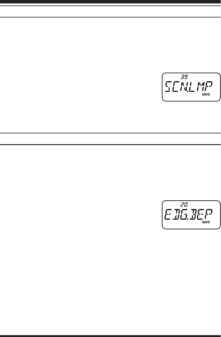
1. Press the [SET] key to enter the Set mode.
2. Rotate the DIAL knob or press the [p]/[q] key to select
Set Mode Item 20: EDG.BEP.
3. Press the [F/W] key momentarily to enable adjustment of
this Set Mode Item.
4. Rotate the DIAL knob or press the [p]/[q] key to set this Set Mode Item to “BEP.
ON.”
5. When you have made your selection, press the PTT switch to save the setting and
exit to normal operation.
Scanning
FCC ID: K6620534X20 / IC: 511B-20534X20
YAESU MUSEN CO., LTD.

FT-257 OperaTing Manual 37
The FT-257 includes an “Emergency” feature which may be useful if you have some-
one monitoring on the same frequency as your transceiver’s “Home” channel. See page
23 for details on setting up the Home channel.
The “Emergency” feature is activated by pressing and holding in the [SET] key for one
second. When this is done, (A) the radio is placed on the Home channel, (B) it emits
a loud “Alarm” sound (the volume is controlled by the DIAL knob), (C) it ashes the
LCD lamp, (D) if you press the PTT switch, you will disable the Emergency feature
temporarily; you can then transmit on the Home channel, and (E) two seconds after the
PTT switch release, the Emergency feature will resume.
To disable the “Emergency” feature, press the [SET] key momentarily or turn the radio
off by pressing the [POWER] switch.
Use this feature if you are out for a walk and want a quick way of alerting a family
member as to a dangerous situation. The alarm sound may discourage an attacker and
allow you to escape.
1) Be sure to arrange with a friend or family member to be monitoring on the same
frequency, as there will be no identication sent via the Emergency alarm sound.
And do not transmit the alarm tone except in a true emergency!
2) The “Emergency” feature may be changed to another function via Set Mode Item
21: EMG S; see page 57 for details.
Emergency Channel Operation
FCC ID: K6620534X20 / IC: 511B-20534X20
YAESU MUSEN CO., LTD.

FT-257 OperaTing Manual38
The Smart Search feature allows you to load frequencies automatically according to
where activity is encountered by your radio. When Smart Search is engaged, the trans-
ceiver will search above and below your current frequency, storing active frequencies as
it goes (without stopping on them even momentarily); these frequencies are stored into
a special Smart Search memory bank, consisting of 31 memories (15 above the current
frequency, 15 below the current frequency, plus the current frequency itself).
Two basic operating modes for Smart Search are available:
SINGLE: In this mode, the transceiver will sweep the current band once in each direc-
tion starting on the current frequency. All channels where activity is present
will be loaded into the Smart Search memories; whether or not all 31 memo-
ries are lled, the search will stop after one sweep in each direction.
CONT: In this mode, the transceiver will make one pass in each direction as with One-
Shot searching; if all 31 channels are not lled after the rst sweep, however,
the radio will continue sweeping until they are all lled.
Setting the Smart Search Mode
1. Press the [SET] key to enter the Set mode.
2. Rotate the DIAL knob or press the [p]/[q] key to select
Set Mode Item 37: S SRCH.
3. Press the [F/W] key momentarily to enable adjustment of
this Set Mode Item.
4. Rotate the DIAL knob or press the [p]/[q] key to select
the desired Smart Search mode (see above).
5. When you have made your selection, press the PTT
switch to save the setting and exit to normal operation.
Storing Smart Search Memories
1. Set the radio to the VFO mode. Be sure that you have the Squelch adjusted properly (so
that band noise is quieted).
2. Press the [F/W] key, then press the [H/L] key to begin the Smart Search scanning.
3. As active channels are detected, you will observe the number of “loaded” channels
increasing in the regular memory channel window.
4. Depending on the mode you set for Smart Search opera-
tion (“SINGLE” or “CONT”), the Smart Search scan will
eventually terminate, and the LCD will revert to Smart
Search Memory Channel “C.”
5. To recall the Smart Search memories, rotate the DIAL knob to choose from among
the frequencies stored by Smart Search.
6. To return to normal operation, press the [VFO(PRI)] key.
Smart Search Operation
FCC ID: K6620534X20 / IC: 511B-20534X20
YAESU MUSEN CO., LTD.
FT-257 OperaTing Manual 39
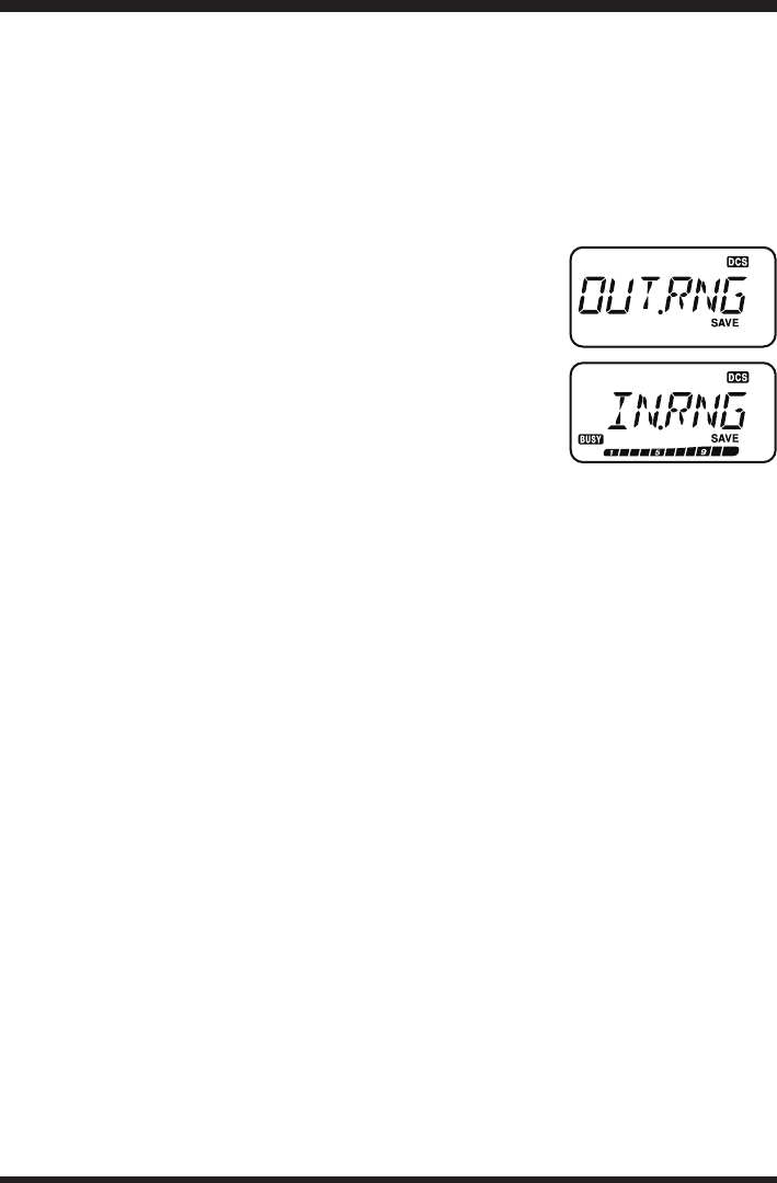
The ARTS™ feature uses DCS signaling to inform both parties when you and another
ARTS™-equipped station are within communications range. This may be particularly
useful during Search-and Rescue situations, where is important to stay in contact with
other members of your group.
Both stations must set up their DCS codes to the same code number, then activate their
ARTS™ feature using the command appropriate for their radio. Alert ringers may be ac-
tivated, if desired.
Whenever you push the PTT switch, or every 25 (or 15)
seconds after ARTS™ is activated, your radio will transmit a
signal which includes a (subaudible) DCS signal for about 1
second. If the other radio is in range, the beeper will sound (if
enabled) and the display will show “IN.RNG” as opposed to
the out of range display “OUT.RNG” in which ARTS™ op-
eration begins.
Whether you talk or not, the polling every 15 or 25 seconds
will continue until you de-activate ARTS™. Every 10 minutes, moreover, you can have
your radio transmit your callsign via CW, so as to comply with identication require-
ments. When ARTS™ is de-activated, DCS will also be deactivated (if you were not us-
ing it previously in non-ARTS™ operation).
If you move out of range for more than one minute (four pollings), your radio will sense
that no signal has been received, three beeps will sound, and the display will revert to
“OUT.RNG.” If you move back into range, your radio will again beep, and the display
will change back to the “IN.RNG” indication.
During ARTS™ operation, your operating frequency will continue to be displayed, but
no changes may be made to it or other settings; you must terminate ARTS™ in order to
resume normal operation. This is a safety feature designed to prevent accidental loss of
contact due to channel change, etc.
Basic ARTS™ Setup and Operation
1. Set your radio and the other radio(s) to the same DCS code number, per the discus-
sion on page 18.
2. Press the [POWER] key momentarily. You will observe the “OUT. RNG” display
on the LCD below the operating frequency. ARTS™ operation has now commenced.
3. Every 25 seconds, your radio will transmit a “polling” call to the other station. When
that station responds with its own ARTS™ polling signal, the display will change to
“IN.RNG” to conrm that the other station’s polling code was received in response
to yours.
4. Press the [POWER] key momentarily to exit ARTS™ operation and resume normal
functioning of the transceiver.
ArtS™ (Automatic Range Transponder System)
FCC ID: K6620534X20 / IC: 511B-20534X20
YAESU MUSEN CO., LTD.
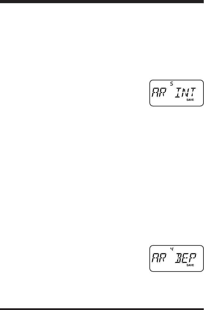
FT-257 OperaTing Manual40
ARTS™ constitutes a form of “remote control” operation that may be restricted to
certain frequencies. U.S. users should conrm the current status of §97.201(b) of the
FCC’s rules governing the 144 MHz band of the Amateur service before utilizing this
feature.
ARTS™ Polling Time Options
The ARTS™ feature may be programmed to poll every 25 seconds (default value) or 15
seconds. The default value provides maximum battery conservation, because the polling
signal is sent out less frequently. To change the polling interval:
1. Press the [SET] key to enter the Set mode.
2. Rotate the DIAL knob or press the [p]/[q] key to select
Set Mode Item 5: AR INT.
3. Press the [F/W] key momentarily to enable adjustment of
this Set Mode Item.
4. Rotate the DIAL knob or press the [p]/[q] key to select the desired polling interval
(15 or 25 seconds).
5. When you have made your selection, press the PTT switch to save the new setting
and exit to normal operation.
ARTS™ Alert Beep Options
The ARTS™ feature allows two kinds of alert beeps (with the additional option of turn-
ing them off), so as to alert you to the current status of ARTS™ operation. Depending
on your location and the potential annoyance associated with frequent beeps, you may
choose the Beep mode which best suits your needs. The choices are:
INRANG: The beeps are issued only when the radio rst conrms that you are within
range, but does not re-conrm with beeps thereafter.
ALWAYS: Every time a polling transmission is received from the other station, the
alert beeps will be heard.
OFF: No alert beeps will be heard; you must look at the display to conrm cur-
rent ARTS™ status.
To set the ARTS™ Beep mode, use the following procedure:
1. Press the [SET] key to enter the Set mode.
2. Rotate the DIAL knob or press the [p]/[q] key to select
Set Mode Item 4: AR BEP.
3. Press the [F/W] key momentarily to enable adjustment of
this Set Mode Item.
4. Rotate the DIAL knob or press the [p]/[q] key to select the desired ARTS™ Beep
mode (see above).
5. When you have made your selection, press the PTT switch to save the new setting
and exit to normal operation.
ArtS™ (Automatic Range Transponder System)
FCC ID: K6620534X20 / IC: 511B-20534X20
YAESU MUSEN CO., LTD.
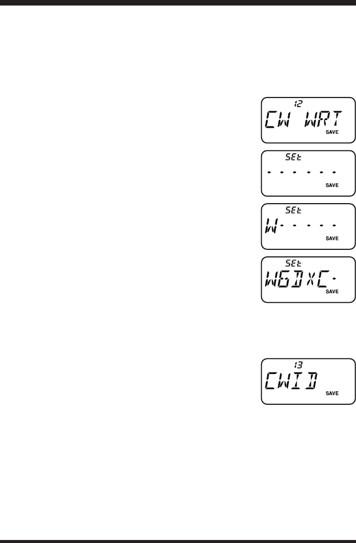
FT-257 OperaTing Manual 41
CW Identier Setup
The ARTS™ feature includes a CW identier, as discussed previously. Every ten min-
utes during ARTS™ operation, the radio can be instructed to send “DE (your callsign) K”
if this feature is enabled. The callsign eld may contain up to 6 characters.
Here’s how to program the CW Identier:
1. Press the [SET] key to enter the Set mode.
2. Rotate the DIAL knob or press the [p]/[q] key to select
Set Mode Item 12: CW WRT.
3. Press the [F/W] key momentarily to display any previous-
ly-stored callsign.
4. Press the [F/W] key again to clear any previous callsign.
5. Rotate the DIAL knob to select the rst letter/number of
your callsign, then press the [F/W] key momentarily to
save the rst letter/number and move on to the next char-
acter.
6. Repeat the previous step, as many times as necessary, to
complete your callsign. If you make a mistake, press the
[q] key to move back to the previous letter/number’s slot,
then re-select the correct letter/number.
7. When you have nished entering your entire callsign and
it contains less than 6 characters, press and hold in the
[F/W] key for one second to conrm the callsign. (if you
callsign has exactly 6 characters, you do not need to press and hold in [F/W] in this
step).
8. Press the PTT switch to save the settings and exit to normal operation.
9. Press the [SET] key to enter the Set mode.
10. Rotate the DIAL knob or press the [p]/[q] key to select
Set Mode Item 13: CWID.
11. Press the [F/W] key momentarily, then rotate the DIAL
knob to set this Item to “TX ON” (to enable the CW ID
function).
12. Press the PTT switch to save the settings and exit to normal operation.
ArtS™ (Automatic Range Transponder System)
FCC ID: K6620534X20 / IC: 511B-20534X20
YAESU MUSEN CO., LTD.
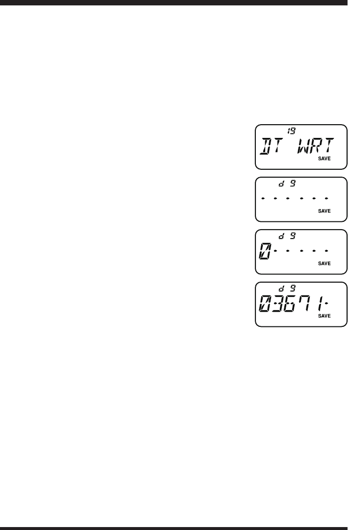
FT-257 OperaTing Manual42
DTMF Operation
Despite the lack of a DTMF keypad, you can still transmit DTMF tones with the FT-
257 for repeater control or autopatch use.
DTMF Autodialer
Nine DTMF Autodial memories are provided, allowing you to store telephone num-
bers for autopatch use. You can also store short autopatch or Internet-link access code
streams so as to avoid having to send them manually.
Here is the DTMF Autodial storage procedure:
1. Press the [SET] key to enter the Set mode.
2. Rotate the DIAL knob or press the [p]/[q] key to select
Set Mode Item 19: DT WRT.
3. Press the [F/W] key momentarily to enable adjustment of
this Set Mode Item.
4. Rotate the DIAL knob to select the DTMF Memory reg-
ister (“d1” ~ “d9”) into which you wish to store this
DTMF string.
5. Press the [F/W] key momentarily to begin DTMF Memory
entry into the selected register.
6. Rotate the DIAL knob to select the rst digit of the DTMF
string. Selectable entries are 0 - 9, and A - F, with E and F
representing DTMF “” and “#” tones respectively.
7. Press the [F/W] key to accept the rst digit and move to
the next digit of the DTMF string.
8. Repeat steps 5 and 6 until you have completed the tele-
phone number.
9. If you make a mistake, press the [q] key to move back to the previous digit, then re-
select the correct number.
10. If the telephone number made up of numbers only, you may key in the telephone
number directly from the keypad.
11. Press and hold in the [F/L] key for one second to save the setting.
12. If you store other numbers, repeat steps 4- 10 above, using a different DTMF memo-
ry register.
13. When all required DTMF memories are lled to your satisfaction, press the PTT
switch to save the settings and exit to normal operation
FCC ID: K6620534X20 / IC: 511B-20534X20
YAESU MUSEN CO., LTD.

FT-257 OperaTing Manual 43
To send the telephone number:
1. Press and hold the PTT switch to continue transmitting during following steps.
A. Press the [p] or [q] key to select the DTMF Memory register ([d 1] through [d 9])
you wish to send.
B. Press the [F/L] key momentarily to transmit the tone string.
Once the string begins, you may release the PTT switch, asthe transmitter will be
held “on the air” until the DTMF string is completed.
You can change the DTMF Autodialer sending speed, using Set Mode Item 18: DT
SPD. See page 57 for details.
You can also set a longer delay between the time you press the numerical key (corre-
sponding to the DTMF memory string; with PTT switch pressed) and the instant when
the rst DTMF digit is sent, using Set Mode Item 17: DT DLY. See page 57 for details.
When you activate the ANI (Automatic Number Identication) feature during DTMF
operation, the DTMF tones stored in ANI memory will automatically be sent whenever
you press the PTT switch.
DTMF Operation
FCC ID: K6620534X20 / IC: 511B-20534X20
YAESU MUSEN CO., LTD.
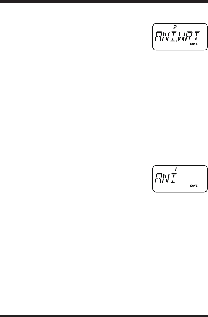
FT-257 OperaTing Manual44
DTMF Operation
Storing the ANI code
1. Press the [SET] key to enter the Set mode.
2. Rotate the DIAL knob or press the [p]/[q] key to select
Set Mode Item 2: ANI.WRT.
3. Press the [F/W] key momentarily to display any previous-
ly-stored ANI code.
4. Press the [F/W] key again to clear any previous ANI code.
5. Rotate the DIAL knob to select the rst number/letter (0-9, A, B, C, D, E (substitute
for “”), and F (substitute for “#”), then press the [F/W] key momentarily to save
the rst letter/number and move on to the next character.
6. Repeat the previous step, as many times as necessary (up to 16 characters), to com-
plete ANI code. If you make a mistake, press the [q] key to move back to the previ-
ous letter/number’s slot, then re-select the correct letter/number.
7. When you have nished entering the ANI code and it contains less than 16 charac-
ters, press and hold in the [F/W] key for one second to conrm the callsign. (if the
ANI code has exactly 16 characters, you do not need to press and hold in [F/W] in
this step).
8. Press the PTT switch to save the settings and exit to normal operation.
Activating the ANI feature
1. Press the [SET] key to enter the Set mode.
2. Rotate the DIAL knob or press the [p]/[q] key to select
Set Mode Item 1: ANI.
3. Press the [F/W] key momentarily to enable adjustment of
this Set Mode Item.
4. Rotate the DIAL knob or press the [p]/[q] key to select “ON.”
5. Press the PTT switch to save the new setting and activate the ANI feature.
6. Press the PTT switch to send the DTMF tones stored in ANI memory.
7. To disable the ANI feature, just repeat the above procedure, rotating the DIAL knob
or press the [p]/[q] key to select “OFF” in step 4 above.
FCC ID: K6620534X20 / IC: 511B-20534X20
YAESU MUSEN CO., LTD.
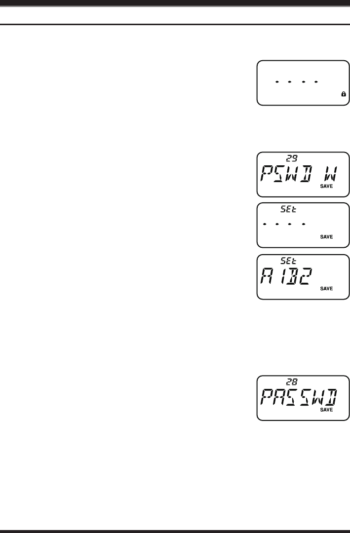
FT-257 OperaTing Manual 45
Password
The FT-257 provides a security password feature which can minimize the chance that
your transceiver could be used by an unauthorized party.
When the password feature is activated, the radio will ask for
the four digit password to be entered when the radio is rst
turned on. You must enter the four digit password from the
keypad. If the wrong password is entered, the microprocessor
will shut down the radio automatically.
To enter the password , use the following procedure:
1. Press the [SET] key to enter the Set mode.
2. Rotate the DIAL knob or press the [p]/[q] key to select
Set Mode Item 29: PSWD W.
3. Press the [F/W] key, then press the [F/W] key again to
clear any previous password.
4. Rotate the DIAL knob to select the rst digit of the desired
number/letter (0-9, A, B, C, D, E, and F).
5. Press the [F/W] key to move to the next digit.
6. Repeat steps 4 and 5 to program the remaining numbers/
letters of the desired password.
7. If you make a mistake, press the [q] key to move back to
the previous digit, then re-select the correct number/letter.
8. When you have nished entering the password, press the
PTT switch to save the new setting and exit to normal operation.
We recommend that you to write down the password number, and keep it in a safe
place you can easily nd if you forget your password.
To Activate the Password feature:
1. Press the [SET] key to enter the Set mode.
2. Rotate the DIAL knob or press the [p]/[q] key to select
Set Mode Item 28: PASSWD.
3. Press the [F/W] key momentarily to enable adjustment of
this Item.
4.
Rotate the DIAL knob or press the [p]/[q] key to set this Set Mode Item to “PWD. ON.”
5. When you have made your selection, press the PTT switch to save the new setting
and exit to normal operation.
6. If you wish to disable the Password feature, just repeat the above procedure, rotat-
ing the DIAL knob to select “PWD.OFF” in step 4 above.
If you forget the password number, you may turn on the transceiver by performing the
“All Reset” procedure (see page 52). However, the FT-257 will clear the password, as
well as all memories, and will restore all other settings to factory defaults.
Miscellaneous Settings
FCC ID: K6620534X20 / IC: 511B-20534X20
YAESU MUSEN CO., LTD.
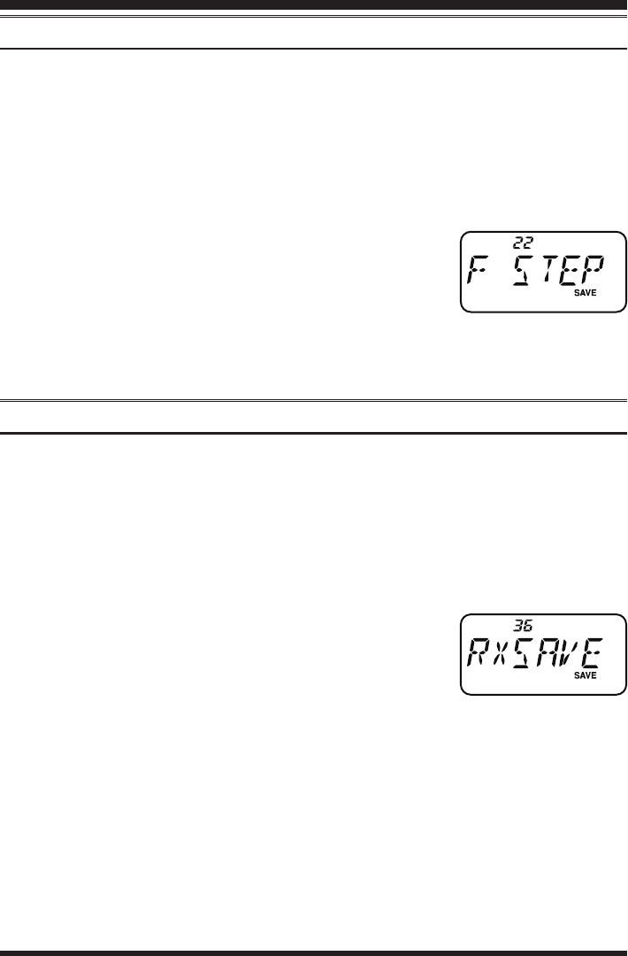
FT-257 OperaTing Manual46
Changing the Channel Steps
The FT-257’s synthesizer provides the option of utilizing channel steps of
5/10/12.5/15/20/25/50/100 kHz per step, as well as an automatic step selection based on
the current operating frequency (“AUTO”), any number of which may be important to
your operating requirements. The FT-257 is set up at the factory in the “AUTO” con-
guration, which probably is satisfactory for most operation. However, if you need to
change the channel step increments, the procedure to do so is very easy.
1. Press the [SET] key to enter the Set mode.
2. Rotate the DIAL knob or press the [p]/[q] key to select
Set Mode Item 22: F STEP.
3. Press the [F/W] key momentarily to enable adjustment of
this Item.
4. Rotate the DIAL knob or press the [p]/[q] key to select the new channel step size.
5. When you have made your selection, press the PTT switch to save the new setting
and return to normal operation.
Receive Battery Saver Setup
An important feature of the FT-257 is its Receive Battery Saver, which “puts the ra-
dio to sleep” for a time interval, periodically “waking it up” to check for activity. If
somebody is talking on the channel, the FT-257 will remain in the “active” mode, then
resume its “sleep” cycles. This feature significantly reduces quiescent battery drain,
and you may change the amount of “sleep” time between activity checks using the Set
Mode:
1. Press the [SET] key to enter the Set mode.
2. Rotate the DIAL knob or press the [p]/[q] key to select
Set Mode Item 36: RXSAVE.
3. Press the [F/W] key momentarily to enable adjustment of
this Item.
4. Rotate the DIAL knob or press the [p]/[q] key to select the desired “sleep” duration.
The selections available are 200 ms, 300 ms, 500 ms, 1 second, 2 seconds, or OFF.
The default value is 200 ms.
5. When you have made your selection, press the PTT switch to save the new setting
and exit to normal operation.
Miscellaneous Settings
FCC ID: K6620534X20 / IC: 511B-20534X20
YAESU MUSEN CO., LTD.
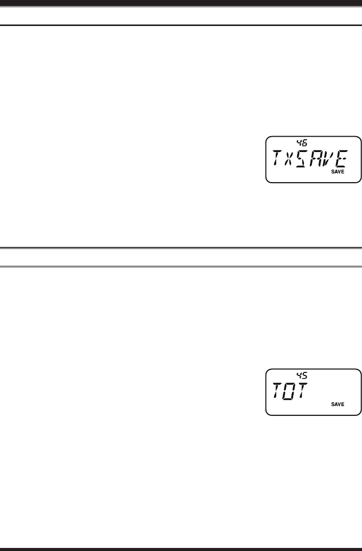
FT-257 OperaTing Manual 47
Miscellaneous Settings
TX Battery Saver
The FT-257 also includes a useful Transmit Battery Saver, which will automatically
lower the power output level when the last signal received was very strong. For ex-
ample, when you are in the immediate vicinity of a repeater station, there generally is
no reason to use the High Power output in order to achieve full-quieting access to the
repeater. With the Transmit Battery Saver, the automatic selection of Low Power opera-
tion conserves battery drain signicantly.
To activate the Transmit Battery Saver:
1. Press the [SET] key to enter the Set mode.
2. Rotate the DIAL knob or press the [p]/[q] key to select
Set Mode Item 46: TXSAVE.
3. Press the [F/W] key momentarily to enable adjustment of
this Set Mode Item.
4. Rotate the DIAL knob or press the [p]/[q] key to set this Set Mode Item to “SAV.
ON” (thus activating the Transmit Battery Saver).
5. When you have made your selection, press the PTT switch to save the new setting
and exit to normal operation.
Transmitter Time-Out Timer (TOT)
The TOT feature provides a safety switch which limits transmission time to a pre-
programmed value. This will promote battery conservation by not allowing you to make
excessively-long transmissions, and in the event of a stuck PTT switch (perhaps if the
radio is wedged between car seats) it can prevent interference to other users as well as
battery depletion. As congured at the factory the TOT feature is set to “6 minutes,” and
here is the procedure for activating it:
1. Press the [SET] key to enter the Set mode.
2. Rotate the DIAL knob or press the [p]/[q] key to select
Set Mode Item 45: TOT.
3. Press the [F/W] key momentarily to enable adjustment of
this Set Mode Item.
4. Rotate the DIAL knob or press the [p]/[q] key to set the Time-Out Timer to the de-
sired “Maximum TX” time (between 1 and 30 minutes), or OFF.
5. When you have made your selection, press the PTT switch to save the new setting
and exit to normal operation.
1) When your transmission time is within 10 seconds of the Time-Out Timer expira-
tion, an Alert bell will provide an audible warning from the speaker.
2) Since brief transmissions are the mark of a good operator, try setting up your ra-
dio’s TOT feature for a maximum transmission time of one minute. This will sig-
nicantly improve battery life, too!
FCC ID: K6620534X20 / IC: 511B-20534X20
YAESU MUSEN CO., LTD.

FT-257 OperaTing Manual48
Busy Channel Lock-Out (BCLO)
The BCLO feature prevents the radio’s transmitter from being activated if a signal
strong enough to break through the “noise” squelch is present. On a frequency where
stations using different CTCSS or DCS codes may be active, BCLO prevents you from
disrupting their communications accidentally (because your radio may be muted by its
own Tone Decoder). The default setting for the BCLO is OFF, and here is how to change
that setting:
1. Press the [SET] key to enter the Set mode.
2. Rotate the DIAL knob or press the [p]/[q] key to select
Set Mode Item 8: BCLO.
3. Press the [F/W] key momentarily to enable adjustment of
this Set Mode Item.
4. Rotate the DIAL knob or press the [p]/[q] key to set this Set Mode Item to “BCL.
ON” (thus activating the BCLO feature).
5. When you have made your selection, press the PTT switch to save the new setting
and exit to normal operation.
DCS Code Inversion
The DCS system was rst introduced in the commercial LMR (Land Mobile Radio)
service, where it is now in widespread use. DCS is sometime referred to by its different
proprietary names, such as DPL® (Digital Private Line®, a registered trademark of Mo-
torola, Inc.).
DCS uses a codeword consisting of a 23-bit frame, transmitted (subaudible) at a data
rate of 134.4 bps (bit/sec). Occasionally, signal inversion can result in the complement
of a code to be sent or received. This prevents the receiver’s squelch from opening with
DCS enabled, as the decoded bit sequence would not match that selected for operation.
Typical situations that might cause inversion to occur are:
Connection of an external receiver preamplier.
Operating through a repeater.
Connection of an external linear amplier.
Note that code inversion does not mean that any of the above listed equipment is defec-
tive!
In certain amplier congurations, the output signal (phase) is inverted from the input.
Small signal or power ampliers having an odd number (1, 3, 5, etc.) of amplication
stages may result in inversion of a transmitted or received DCS code.
While under most circumstances this should not occur (amplier designs and industry
Miscellaneous Settings
FCC ID: K6620534X20 / IC: 511B-20534X20
YAESU MUSEN CO., LTD.
FT-257 OperaTing Manual 49
standards take this into account), if you nd that your receiver squelch does not open
when both you and the other station are using a common DCS code, you or the other
station (but not both) can try the following:
1. Press the [SET] key to enter the Set mode.
2. Rotate the DIAL knob or press the [p]/[q] key to select
Set Mode Item 16: DCS.N/R.
3. Press the [F/W] key momentarily, then rotate the DIAL
knob or press the [p]/[q] key to select one of the follow-
ing modes:
T/RX N: Encoder, Normal; Decoder, Normal
RX R: Encoder, Normal; Decoder, Reverse (Inverted)
TX R: Encoder, Reverse (Inverted); Decoder, Normal
T/RX R: Encoder, Reverse (Inverted); Decoder, Reverse (Inverted)
4. When you have made your selection, press the PTT switch to save the new setting
and exit to normal operation.
5. Remember to restore the default setting to “T/RX N” (Encoder; Normal, Decoder;
Normal) when done.
Changing the TX Deviation Level
In many areas of the world, channel congestion has required that operating channels be
closely spaced. In such operating environments, it often is required that operators use re-
duced deviation levels, so as to reduce the potential for interference to users on adjacent
channels. The FT-257 includes a simple method of accomplishing this:
1. Press the [SET] key to enter the Set mode.
2. Rotate the DIAL knob or press the [p]/[q] key to select
Set Mode Item 47: WID.NAR.
3. Press the [F/W] key momentarily to enable adjustment of
this Set Mode Item.
4. Rotate the DIAL knob or press the [p]/[q] key to set this Set Mode Item to “NAR-
ROW.” In this conguration (HALF DEVIATION active), the transmitter’s devia-
tion will be approximately ±2.5 kHz, and the received audio output level will be
increased, for easier listening on the narrow signal.
5. When you have made your selection, press the PTT switch to save the new setting
and exit to normal operation.
The “normal” setting for the deviation (when this Menu Item is set to WIDE) is ±5
kHz.
Miscellaneous Settings
FCC ID: K6620534X20 / IC: 511B-20534X20
YAESU MUSEN CO., LTD.

FT-257 OperaTing Manual50
In the event of erratic operation of the transceiver, it is possible that data on the micro-
processor may have become corrupted. While this is a highly unusual situation, the only
path to recovery may involve resetting of the microprocessor. Here’s how to do this:
1. Turn the radio off.
2. Press and hold in the [V/M] key while turning the radio on.
3. Rotate the DIAL knob to select one of the choices from the reset menu:
F1 SETRST: Resets the Set (Menu) mode settings to their factory defaults.
F2 MEMRST: Clears the Memory settings to factory defaults.
F3 MB RST: Clears the Memory Bank Assignments.
F4 ALLRST: Clears all memories and other settings to factory defaults.
4. Press the [V/M] key momentarily to complete the reset procedure.
The “F5” option is used for setting up the “Memory Only” mode. See page 27 for de-
tails regarding the memory Only mode.
Reset Procedures
FCC ID: K6620534X20 / IC: 511B-20534X20
YAESU MUSEN CO., LTD.
FT-257 OperaTing Manual 51
The FT-257 Set Mode, already described in parts of many previous chapters, is easy to
activate and set. It may be used for conguration of a wide variety of transceiver param-
eters, some of which have not been detailed previously. Use the following procedure to
activate the Set Mode:
1. Press the [SET] key to enter the Set mode.
2. Rotate the DIAL knob or press the [p]/[q] key to select
the Set Mode Item to be adjusted.
3. Press the [F/W] key momentarily to enable adjustment of
the Set Mode Item.
4. Rotate the DIAL knob or press the [p]/[q] key to adjust or select the parameter to be
changed on the Set Mode Item selected in above step.
5. After completing your selection and adjustment, press the PTT switch momentarily
to save the new setting and exit to normal operation.
Some Set Mode Items (like Set Mode Item 44: TN FRQ) require that the [F/W] key be
pressed after setting of the parameter, and before exiting to normal operation.
Set (Menu) Mode
Set Mode iteM
1 [ANI]
2 [ANI.WRT]
3 [APO]
4 [AR BEP]
5 [AR INT]
6 [ARS]
8 [BCLO]
9 [BEEP]
10 [BELL]
11 [CLK.SFT]
12 [CW WRT]
13 [CWID]
14 [DC VLT]
15 [DCS.COD]
16 [DCS.N/R]
17 [DT DLY]
18 [DT SPD]
19 [DT WRT]
20 [EDG.BEP]
21 [EMG S]
22 [F STEP]
23 [LAMP]
24 [LOCK]
Function
Enables/Disables the ANI function.Setting of the Automatic
Program the ANI Identier.
Power-Off feature.
Selects the Beep option during ARTS operation.
Selects the Polling Interval during ARTS operation.
Enables/Disables the Automatic Repeater Shift function.
Enables/Disables the Busy Channel Lock-Out feature.
Enables/Disables the beeper.
Selects the number of CTCSS/DCS Bell ringer repetitions.
Shifting of the CPU clock frequency.
Programs and activates the CW Identier.
Enables/disables the CW identier during ARTS operation.
Indicates the DC Supply Voltage.
Setting of the DCS code.
Enables/Disables “Inverted” DCS code decoding.
Setting of the DTMF Autodialer Delay Time.
Setting of the DTMF Autodialer Sending Speed.
Programming of the DTMF Autodialer.
Enables/Disables the Band-edge beeper while selecting the
frequency via the DIAL knob.
Selects the alarm(s) utilized when the Emergency function is
engaged.
Setting of the synthesizer steps.
Selects the LCD/Keypad Lamp mode.
Selects the Control Locking lockout combination.
AvAiLAbLe vALueS
(deFAuLt: Bold ItalIc)
ANI.OFF/ANI. ON
---
OFF / 0.5H - 12.0 H
INRANG / ALWAYS / OFF
25 SEC / 15 SEC
ARS. ON / ARS.OFF
BCL. ON / BCL.OFF
KEY+SC / KEY / OFF
OFF / 1T / 3T /
5T / 8T / CONT
SFT.OFF / SFT. ON
---
TX OFF / TX ON
---
104 DCS codes (023)
T/RX N, RX R,
TX R, T/RX R
50MS / 100MS / 250MS /
450MS / 750MS / 1000MS
50MS / 100MS
---
BEP.OFF / BEP. ON
EMG.BEP / EMG.LMP / EMG.
B+L / EMG.CWT / EMG.C+B
/ EMG.C+L / EMG.ALL / OFF
5 / 10 / 12.5 / 15 / 20 / 25 / 50
/ 100 kHz, or AUTO
KEY / CONT / OFF
LK KEY / LKDIAL / LK K+D /
LK PTT / LK P+K /
LK P+D / LK ALL
FCC ID: K6620534X20 / IC: 511B-20534X20
YAESU MUSEN CO., LTD.
FT-257 OperaTing Manual52
Set (Menu) Mode
Function
Selects the [VOL/SQL] key function.
Toggles the display indication between “frequency” and the
channel’s “Alpha/Numeric Tag.”
Stores Alpha-Numeric “Tags” for the Memory channels.
Enables/disables the Password feature.
Stores the password.
Sets the magnitude of the repeater Shift.
Selects the Scan Resume mode.
Selects the function of the [HM/RV] key.
Adjusts the RF Squelch threshold level.
Sets the Repeater Shift Direction.
Enables/disables the Priority Revert feature.
Selects the Receive-mode Battery Saver interval (“sleep” ratio)
Selects the Smart Search Sweep mode.
Selects the Memory Scan channel-selection mode.
Enables/Disables the Scan lamp while paused.
Selects the Memory Scan “Skip” channel-selection mode.
Enables or disables “VFO Split” operation.
Selects the Tone Encoder and/or Decoder mode.
Indicate the current temperature inside the transceiver’s case.
Setting of the CTCSS Tone Frequency.
Setting of the TOT time.
Enables/Disables the Transmitter Battery Saver.
Select Wide (±5 kHz) or Narrow (±2.5 kHz) TX Deviation.
AvAiLAbLe vALueS
(deFAuLt: Bold ItalIc)
MONI / T-CALL
FREQ / ALPHA
---
PWD.OFF / PWD. ON
---
0.00 - 99.95 MHz (0.60 MHz)
BUSY / HOLD / TIME
<
REV
>
/
<
HOME
>
S-1 / S-2 / S-3 / S-4 / S-5 /
S-6 / S-8 / S-FULL / OFF
RPT.OFF / RPT.– / RPT. +
RVT.OFF / RVT. ON
200 MS / 300 MS /500 MS /
1 SEC / 2 SSEC / OFF
SINGLE / CONT
ONLY / MEM
ON / OFF
OFF / SKIP / ONLY
SPL.OFF / SPL. ON
OFF / TONE / TSQL /
REV TN / DCS / ECS
---
50 CTCSS tones (100 Hz)
1MIN - 30MIN or OFF (6 MIN)
SAV.OFF / SAV. ON
WIDE / NARROW
Set Mode iteM
25 [M/TCAL]
26 [NAME]
27 [NM WRT]
28 [PASSWD]
29 [PSWD W]
30 [R SHFT]
31 [RESUME]
32 [REV/HM]
33 [RF SQL]
34 [RPT.MOD]
35 [PRI.RVT]
36 [RXSAVE]
37 [S SRCH]
38 [SCN MD]
39 [SCN.LMP]
40 [SKIP]
41 [SPLIT]
42 [SQL.TYP]
43 [TEMP]
44 [TN FRQ]
45 [TOT]
46 [TXSAVE]
47 [WID.NAR]
FCC ID: K6620534X20 / IC: 511B-20534X20
YAESU MUSEN CO., LTD.

FT-257 OperaTing Manual 53
Set Mode Item 1 [ANI]
Function: Enables/Disables the ANI function.
Available Values: ANI.OFF/ANI. ON
Default: ANI. OFF
Set Mode Item 2 [ANI.WRT]
Function: Program the ANI Identier.
See page 46 for details.
Set Mode Item 3 [APO]
Function: Setting of the Automatic Power-Off feature.
Available Values: OFF/0.5H - 12.0 H in 0.5 hour multiples
Default: OFF
Set Mode Item 4 [AR BEP]
Function: Selects the Beep option during ARTS operation.
Available Values: INRANG/ALWAYS/OFF
Default: INRANG
INRANG: Beeps sound only when the radio rst detects that you are within range.
ALWAYS: Beeps sound every time a polling transmission is received from the other sta-
tion (every 15 or 25 seconds when in range).
OFF: No alert beeps sound.
Set Mode Item 5 [AR INT]
Function: Selects the Polling Interval during ARTS operation.
Available Values: 25 SEC/15 SEC
Default: 25SEC
Set Mode Item 6 [ARS]
Function: Enables/Disables the Automatic Repeater Shift function.
Available Values: ARS. ON/ARS.OFF
Default: ARS. ON
Set Mode Item 8 [BCLO]
Function: Enables/Disables the Busy Channel Lock-Out feature.
Available Values: BCL. ON/BCL.OFF
Default: BCL.OFF
Set (Menu) Mode
FCC ID: K6620534X20 / IC: 511B-20534X20
YAESU MUSEN CO., LTD.

FT-257 OperaTing Manual54
Set Mode Item 9 [BEEP]
Function: Enables/Disables the beeper.
Available Values: KEY+SC/KEY/OFF
Default: KEY+SC
KEY+SC: The beeper sounds when you press any key, or when the scanner stops.
KEY: The beeper sounds when you press any key.
OFF: Beeper is disabled.
Set Mode Item 10 [BELL]
Function: Selects the number of CTCSS/DCS Bell ringer repetitions.
Available Values: OFF/1T/3T/5T/8T/CONT (Continuous ringing)
Default: OFF
Set Mode Item 11 [CLK.SFT]
Function: Shifting of the CPU clock frequency.
Available Values: SFT.OFF/SFT. ON
Default: SFT.OFF
This function is only used to move a spurious response “birdie,” should it fall on a de-
sired frequency.
Set Mode Item 12 [CW WRT]
Function: Programs and activates the CW Identier (used during ARTS operation).
See page 41 for details.
Set Mode Item 13 [CWID]
Function: Enables/disables the CW identier during ARTS operation.
Available Values: TX OFF/TX ON
Default: TX OFF
Set Mode Item 14 [DC VLT]
Function: Indicates the DC Supply Voltage.
Set Mode Item 15 [DCS.COD]
Function: Setting of the DCS code.
Available Values: 104 standard DCS codes
Default: DCS.023
Set Mode Item 16 [DCS.N/R]
Function: Enables/Disables “Inverted” DCS
code decoding.
Available Values: T/RX N, RX R, TX R,
T/RX R
Default: T/RX N
Set (Menu) Mode
DCS CODE
023 025 026 031 032 036 043 047 051 053
054 065 071 072 073 074 114 115 116 122
125 131 132 134 143 145 152 155 156 162
165 172 174 205 212 223 225 226 243 244
245 246 251 252 255 261 263 265 266 271
274 306 311 315 325 331 332 343 346 351
356 364 365 371 411 412 413 423 431 432
445 446 452 454 455 462 464 465 466 503
506 516 523 526 532 546 565 606 612 624
627 631 632 654 662 664 703 712 723 731
732 734 743 754 – – – – – –
FCC ID: K6620534X20 / IC: 511B-20534X20
YAESU MUSEN CO., LTD.

FT-257 OperaTing Manual 55
Set Mode Item 17 [DT DLY]
Function: Setting of the DTMF Autodialer Delay Time.
Available Values: 50MS/100MS/250MS/450MS750MS/1000MS
Default: 450MS
Set Mode Item 18 [DT SPD]
Function: Setting of the DTMF Autodialer Sending Speed.
Available Values: 50MS (high speed)/100MS (low speed)
Default: 50MS
Set Mode Item 19 [DT WRT]
Function: Programming of the DTMF Autodialer.
See page 44 for details.
Set Mode Item 20 [EDG.BEP]
Function: Enables/Disables the Band-edge beeper while selecting the frequency via the
DIAL knob.
Available Values: BEP.OFF/ BEP. ON
Default: BEP.OFF
Set Mode Item 21 [EMG S]
Function: Selects the alarm(s) utilized when the Emergency function is engaged.
Available Values: EMG.BEP/EMG.LMP/EMG.B+L/EMG.CWT/EMG.C+B/EMG.
C+L/EMG.ALL/OFF
Default: EMG.B+L
EMG.BEP: Loud “Alarm” sounds.
EMG.LMP: The LCD/Keypad lamp ashes.
EMG.B+L: Loud “Alarm” sounds and the LCD/Keypad lamp ashes.
EMG.CWT: Transmits the Morse Code “SOS” (• • • – – – • • •) message on the air be-
ginning one minute after activation of the Emergency function.
EMG.C+B: Loud “Alarm” sounds and the Morse Code “SOS” (• • • – – – • • •) mes-
sage is transmitted on the air beginning one minute after activation of the
Emergency function.
EMG.C+L: The LCD/Keypad lamp ashes, and the Morse Code “SOS” (• • • – – – • •
•) message is transmitted on the air beginning one minute after activation of
the Emergency function.
EMG.ALL: All of the above are activated.
OFF:
Disables the Emergency function.
When the radio is set to the EMG.CWT, EMG.C+B, EMG.C+L, or EMG.ALL mode,
the radio will be instructed to send “DE (your callsign)” after the sending of the SOS
message, if your callsign is entered via Set Mode Item 13: CWID.
Set (Menu) Mode
FCC ID: K6620534X20 / IC: 511B-20534X20
YAESU MUSEN CO., LTD.

FT-257 OperaTing Manual56
Set Mode Item 22 [F STEP]
Function: Setting of the synthesizer steps.
Available Values: 5/10/12.5/15/20/25/50/100 kHz, or AUTO
Default: AUTO (Step automatically changes according to operating frequency.)
Set Mode Item 23 [LAMP]
Function: Selects the LCD/Keypad Lamp mode.
Available Values: KEY/CONT/OFF
Default: KEY
KEY: Illuminates the Keypad/LCD lamp for ve seconds when you rotate the DIAL
knob or press the keypad or any switch (except PTT switch). This is the facto-
ry-programmed default setting.
CONT: Illuminates the Keypad/LCD lamp continuously.
OFF: Disables the Keypad/LCD lamp.
Set Mode Item 24 [LOCK]
Function: Selects the Control Locking lockout combination.
Available Values: LK KEY/LKDIAL/LK K+D/LK PTT/LK P+K/LK P+D/LK ALL
Default: LK K+D
Note: “K” = “Key;” “D” = “Dial;” and “P” = “PTT.”
Set Mode Item 25 [M/TCAL]
Function: Selects the [VOL/SQL] key function.
Available Values: MONI/T-CALL
Default: Depends on the transceiver version.
MONI: Pressing the [VOL/SQL] key causes the Noise/Tone Squelch to be over-
ridden, allowing you to listen for weak (or non-encoded) signals.
T-CALL: Pressing the [VOL/SQL] key activates a 1750-Hz burst tone, used for repeater
access in many countries (especially in Europe).
Set Mode Item 26 [NAME]
Function: Toggles the display indication between “frequency” and the channel’s “Alpha/
Numeric Tag.”
Available Values: FREQ/ALPHA
Default: FREQ
Set Mode Item 27 [NM WRT]
Function: Stores Alpha-Numeric “Tags” for the Memory channels.
See page 24 for details.
Set Mode Item 28 [PASSWD]
Function: Enables/disables the Password feature.
Available Values: PWD.OFF/PWD. ON
Default: PWD.OFF
Set (Menu) Mode
FCC ID: K6620534X20 / IC: 511B-20534X20
YAESU MUSEN CO., LTD.

FT-257 OperaTing Manual 57
Set Mode Item 29 [PSWD W]
Function: Stores the password.
Available entries are 0-9, A, B, C, D, E, and F.
Set Mode Item 30 [R SHIFT]
Function: Sets the magnitude of the repeater Shift.
Available Values: 0.00 - 99.95 MHz (50 kHz increments)
Default: Depends on the operating band and transceiver version.
Set Mode Item 31 [RESUME]
Function: Selects the Scan Resume mode.
Available Values: BUSY/HOLD/TIME
Default: BUSY
BUSY: The scanner will hold until the signal disappears, then will resume when the
carrier drops.
HOLD: The scanner will stop when a signal is received, and will not restart.
TIME: The scanner will hold for the ve seconds, then resume whether or not the other
station is still transmitting.
Set Mode Item 32 [REV/HM]
Function: Selects the function of the [REV(HOME)] key.
Available Values:
<
REV
>
/
<
HOME
>
Default: <REV>
<
REV
>
: Pressing the [REV(HOME)] key reverses the transmit and receive frequencies
during repeater operation.
<
HOME
>
: Pressing the [REV(HOME)] key instantly recalls a favorite “Home” channel.
Set Mode Item 33 [RF SQL]
Function: Adjusts the RF Squelch threshold level.
Available Values: S-1/S-2/S-3/S-4/S-5/S-6/S-8/S-FULL/OFF
Default: OFF
Set Mode Item 34 [RPT.MOD]
Function: Sets the Repeater Shift Direction.
Available Values: RPT.OFF/RPT. –/RPT. +
Default: Depends on the transceiver version, as well as the setting of Set Mode Item 4:
ARS.
Set Mode Item 35 [PRI.RVT]
Function: Enables/disables the Priority Revert feature.
Available Values: RVT.OFF/RVT. ON
Default: RVT.OFF
See page 36 for details.
Set (Menu) Mode
FCC ID: K6620534X20 / IC: 511B-20534X20
YAESU MUSEN CO., LTD.

FT-257 OperaTing Manual58
Set Mode Item 36 [RXSAVE]
Function: Selects the Receive-mode Battery Saver interval (“sleep” ratio)
Available Values: 200 MS(1:1)/300 MS(1:1.5)/500 MS(1:2.5)/1 S(1:5)/2 S(1:10)/OFF
Default: 200 MS
Set Mode Item 37 [S SRCH]
Function: Selects the Smart Search Sweep mode.
Available Values: SINGLE/CONT
Default: SINGLE
SINGLE: The transceiver sweeps the current band once in each direction, starting on
the current frequency. All channels where activity is present (up to 15 in each
direction) are loaded into the Smart Search memories. Whether or not all 31
memories are lled, the search stops after one sweep in each direction.
CONT: The transceiver makes a sweep in each direction as with the “SINGLE”
mode, but if all 31 channels are not lled after the rst sweep, the radio con-
tinues sweeping until they are all lled.
Set Mode Item 38 [SCN MD]
Function: Selects the Memory Scan channel-selection mode.
Available Values: ONLY/MEM
Default: MEM
ONLY: The scanner will only scan channels that are agged (Preferential Scan List).
MEM: The scanner will “skip” the agged channels during scanning.
Set Mode Item 39 [SCN.LMP]
Function: Enables/Disables the Scan lamp while paused.
Available Values: ON/OFF
Default: ON
Set Mode Item 40 [SKIP]
Function: Selects the Memory Scan “Skip” channel-selection mode.
Available Values: OFF/SKIP/ONLY
Default: OFF
SKIP: The scanner will “skip” the agged channels during scanning.
ONLY: The scanner will only scan channels that are agged (Preferential Scan List).
OFF: All memory channels will be scanned (the “ag” will be ignored).
Set (Menu) Mode
FCC ID: K6620534X20 / IC: 511B-20534X20
YAESU MUSEN CO., LTD.
FT-257 OperaTing Manual 59
Set Mode Item 41 [SPLIT]
Function: Enables/Disables split CTCSS/DCS coding.
Available Values: SPL.OFF/SPL. ON
Default: SPL.OFF
When this Set Mode Item is set to “SPL. ON,” you will see the following additional pa-
rameters after the “DCS” parameter while conguring Set Mode Item 44: SQL.TYP.
D: DCS Encode only.
T DCS: Encodes a CTCSS tone and Decodes a DCS code.
D TSQL: Encodes a DCS code and Decodes a CTCSS tone.
Select the desired operating mode from the selections shown above.
Set Mode Item 42 [SQL.TYP]
Function: Selects the Tone Encoder and/or Decoder mode.
Available Values: OFF/TONE/TSQL/REV TN/DCS/ECS
Default: OFF
TONE: CTCSS Encoder
TSQL: CTCSS Encoder/Decoder
REV TN: Reverse CTCSS Decoder (Mutes receiver when matching tone is received)
DCS: Digital Coded Encoder/Decoder
ECS: Enhanced Paging & & Code Squelch
Note: See also Set Mode Item 41: SPLIT regarding additional selections available dur-
ing “Split Tone” operation.
Set Mode Item 43 [TEMP]
Function: Indicate the current temperature inside the transceiver’s case.
Set Mode Item 44 [TN FRQ]
Function: Setting of the CTCSS Tone Fre-
quency.
Available Values: 50 standard CTCSS tones
Default: 100.0 Hz
Set Mode Item 45 [TOT]
Function: Setting of the TOT time
Available Values: 1MIN - 30MIN or OFF
Default: 6MIN (minutes)
The time-out timer shuts off the transmitter after continuous transmission of the pro-
grammed time.
Set (Menu) Mode
CTCSS TONE FREQUENCY (Hz)
67.0 69.3 71.9 74.4 77.0 79.7
82.5 85.4 88.5 91.5 94.8 97.4
100.0 103.5 107.2 110.9 114.8 118.8
123.0 127.3 131.8 136.5 141.3 146.2
151.4 156.7 159.8 162.2 165.5 167.9
171.3 173.8 177.3 179.9 183.5 186.2
189.9 192.8 196.6 199.5 203.5 206.5
210.7 218.1 225.7 229.1 233.6 241.8
250.3 254.1 – – – –
FCC ID: K6620534X20 / IC: 511B-20534X20
YAESU MUSEN CO., LTD.

FT-257 OperaTing Manual60
Set Mode Item 46 [TXSAVE]
Function: Enables/Disables the Transmitter Battery Saver.
Available Values: SAV.OFF/ SAV. ON
Default: SAV.OFF
Set Mode Item 47 [WID.NAR]
Function: Select Wide (±5 kHz) or Narrow (±2.5 kHz) TX Deviation.
Available Values: WIDE/NARROW
Default: WIDE
Note: If “Narrow” is selected, the receiver audio level is increased slightly to compen-
sate for the reduced deviation. The receiver IF lter bandwidth is not changed via this
setting.
Set (Menu) Mode
FCC ID: K6620534X20 / IC: 511B-20534X20
YAESU MUSEN CO., LTD.

FT-257 OperaTing Manual 61
General
Frequency Ranges: RX 400 - 480 MHz
TX 430 - 440 (450) MHz
Channel Steps: 5/10/12.5/15/20/25/100 kHz
Frequency Stability: ±2.5 ppm @ 14º to 140º F (–10° to +60° C)
Repeater Shift: ±1.6 MHz, ±5 MHz, ±7.6 MHz
Emission Type: F2 , F3
Antenna Impedance: 50
Supply Voltage: Nominal: 7.4 V DC
(Negative Ground) Operating: 5.0 ~ 10.0 V DC (EXT DC Jack)
Current Consumption: 200 mA (Receive, 200 mW output)
(Approx. @7.4 V) 70 mA (Standby, Saver Off)
25 mA (Standby, Saver On)
0.5 mA (Auto Power Off)
1.8 A (5 W TX)
Operating Temperature: –4º to 140º F (–20 °C to +60 °C)
Case Size: 2.45” (W) x 4.74” (H) x 1.52” (D) (62 x 120.5 x 38.5 mm)
(W/O knob, antenna, & belt clip)
Weight: 9.9 Oz (280 g) with FNB-124LI, antenna, and belt clip
Transmitter
RF Power Output: 5.0 W (High) / 2.0 W (Middle) / 0.5 W (Low) (@7.4 V)
Modulation Type: Variable Reactance F2, F3
Maximum Deviation: ±5.0 kHz (F2, F3)
Spurious Emission: At least 60 dB down (@ High and Middle power)
At least 40 dB down (@ Low power)
Microphone Impedance: 2 k
Receiver
Circuit Type: Direct-Conversion
Sensitivity: 0.2 µV for 12 dB SINAD (430-450 MHz)
0.16 µV for 12 dB SINAD (Out of Amateur band)
Selectivity: 12 kHz/35 kHz (–6 dB /–60 dB)
AF Output: 800 mW @ 16 for 10 % THD (Internal Speaker)
(@ 4.8 V)
Specications are subject to change without notice, and are guaranteed within the
430 MHz amateur band only. Frequency ranges and functions will vary according to
transceiver version; check with your dealer.
Specications
FCC ID: K6620534X20 / IC: 511B-20534X20
YAESU MUSEN CO., LTD.

FT-257 OperaTing Manual62
Note
FCC ID: K6620534X20 / IC: 511B-20534X20
YAESU MUSEN CO., LTD.

1. ChangesormodicationstothisdevicenotexpresslyapprovedbyYAESU
MUSENcouldvoidtheuser’sauthorizationtooperatethisdevice.
2. This device complies with part 15 of the FCC Rules. Operation is subject
to the following two conditions: (1) This device may not cause harmful
interference, and (2) this device must accept any interference including
received, interference that may cause undesired operation.
3. The scanning receiver in this equipment is incapable of tuning, or readily
being altered, by the User to operate within the frequency bands allocated
to the Domestic public Cellular Telecommunications Service in Part 22.
WARNING:MODIFICATIONOFTHISDEVICETORECEIVECELLULAR
RADIOTELEPHONESERVICESIGNALSISPROHIBITEDUNDERFCCRULES
ANDFEDERALLAW.
DECLARATION BY MANUFACTURER
The Scanner receiver is not a digital scanner and is incapable of being
convertedormodiedtoadigitalscannerreceiverbyanyuser.
FCC ID: K6620534X20 / IC: 511B-20534X20
YAESU MUSEN CO., LTD.

Copyright 2013
YAESU MUSEN CO., LTD.
All rights reserved.
No portion of this manual
may be reproduced
without the permission of
YAESU MUSEN CO., LTD.
Printed in Japan
EH053U100
FCC ID: K6620534X20 / IC: 511B-20534X20
YAESU MUSEN CO., LTD.