Yaesu Musen 20621X50 HF Transceiver User Manual 05 User Manual
Yaesu Musen Co., Ltd. HF Transceiver 05 User Manual
Contents
- 1. Users Manual Part 1
- 2. Users Manual Part 2
Users Manual Part 2
Page 16 FT-410 OperaTiOn Manual
easy OperaTiOn
reSettiNG the microproceSSor
The FT-410 has two reset methods.
meNu mode reSet
Use this procedure to restore the Menu settings to
their factory defaults, without affecting the memories
you have programmed.
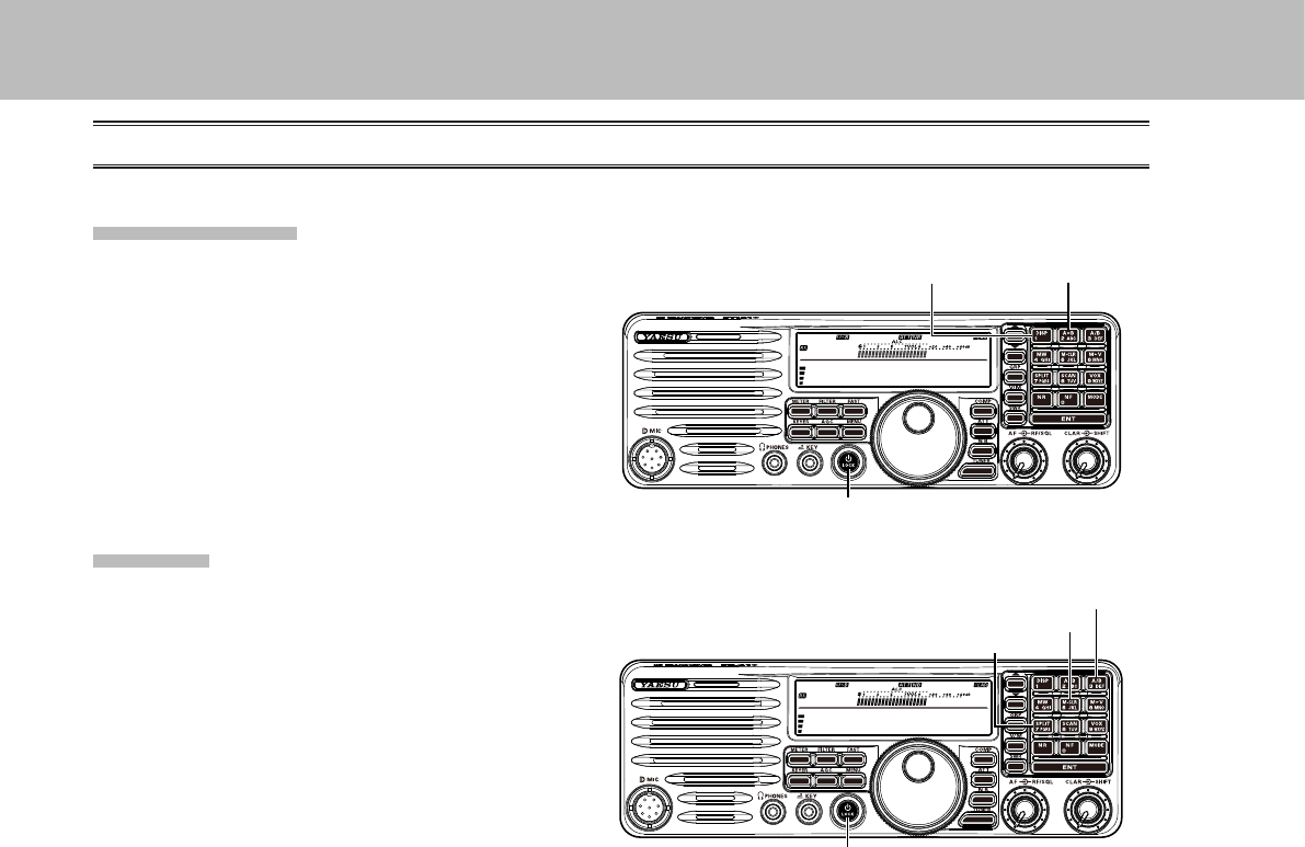
1. Press and hold in the [Power / LOCK] buttons
for one second to turn the transceiver off.
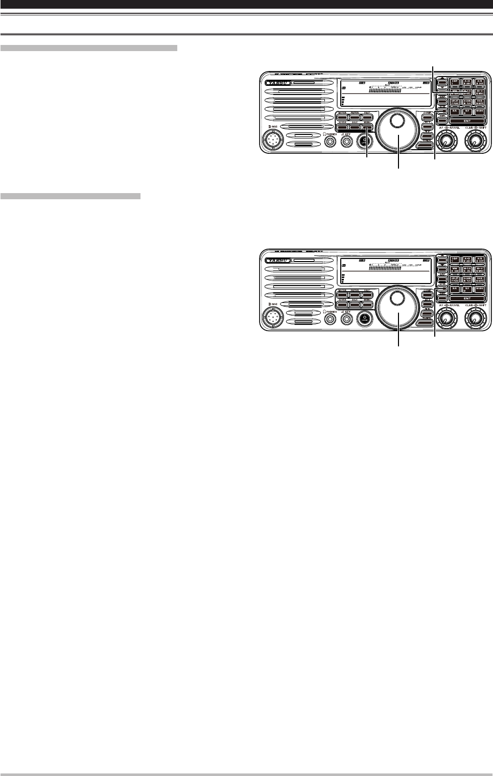
2. Press and hold the [DISP] and [A=B] button.
While holding it in, press and hold in the [Power
/ LOCK] button for one second to turn the
transceiver on. Once the transceiver comes on,
you may release the buttons.
All reSet
Use this procedure to restore all Menu and Memory
settings to their original factory defaults. All
Memories will be cleared by this procedure.
1. Press and hold in the [Power / LOCK] button for
one second to turn the transceiver off.
2. Press and hold the [A/B], [M-CLR] and [SPLIT]
buttons. While holding it in, press and hold in the
[Power / LOCK] button for one second to turn
the transceiver on. Once the transceiver comes
on, you may release the buttons.
14.195.000
M-012
[Power / LOCK] button
[SPLIT] button
[A/B] button
[M-CLR] button
14.195.000
M-012
[Power / LOCK] button
[DISP] button [A=B] button
Application for FCC / IC FCC ID: K6620621X50 IC: 511B-20621X50
Page 17FT-410 OperaTiOn Manual
receiving
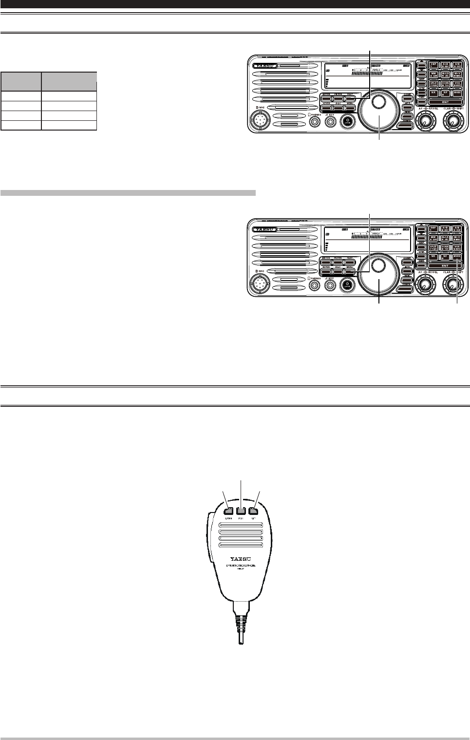
tuNiNG StepS
The tuning step of the [MAIN DIAL] knob on the
operating mode.
OperaTing
MOde
LSB/USB
CW
AM
DATA
[MAIN DIAL]
10 Hz
10 Hz
1 kHz
10 Hz
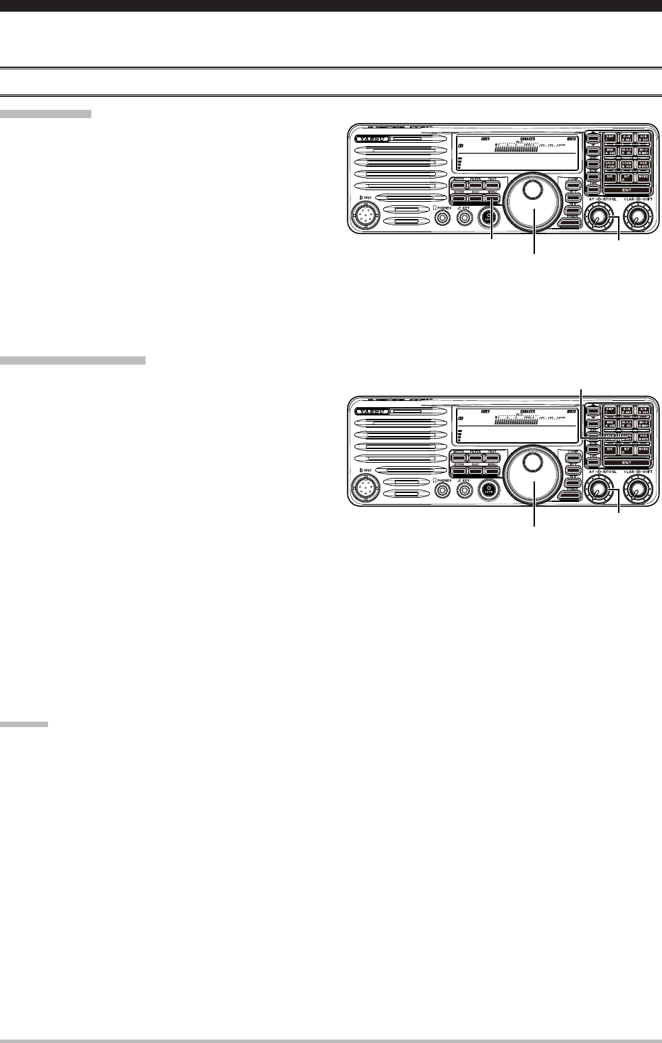
Pressing the [FAST] button will increase or decrease the tuning rate of the [MAIN DIAL] knob by a factor
of ten.
chANGe the tuNiNG Step of the [mAiN diAl] KNob
1. Set the operating mode by pressing the [MODE]
button.
2. Press and hold the [MENU] button for one second
to enter the Menu mode. The “Menu.” will appear
on the display.
3. Rotate the [MAIN DIAL] knob to select the menu
item “Dial Step”.
4. Press the [MAIN DIAL] knob to enable adjustment
of this menu item. The “Menu.” will be blinking.
5. Rotate the [MAIN DIAL] knob to select the desired
tuning step described above.
(You may Press the [MAIN DIAL] button to reset the tuning step to the factory default.)
6. Press the [MENU] button. The “Menu.” is displayed continuously.
7. Press and hold the [MENU] button for one second to save the new setting and return to normal operation.
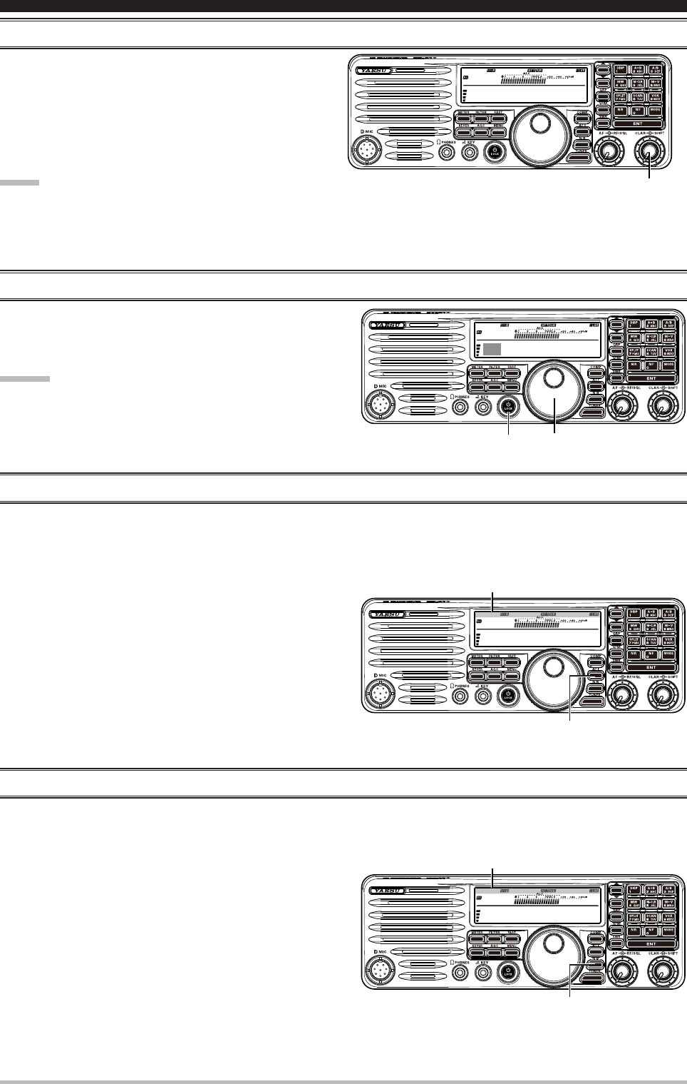
About the [up]/[dwN] buttoNS of the mh-31b8
The microphone [UP]/[DWN] keys utilize the tuning steps of the [MAIN DIAL] knob on the SSB/CW/DATA
mode.
When the microphone [FST] key is pressed, the tuning rate increases by a factor of ten, in a manner
similar to the effect of the transceiver front-panel [FAST] button.
[DWN] Key
[FST] Key
[UP] Key
14.195.000
M-012
[MAIN DIAL] knob
[FAST] button
14.195.000
M-012
[MAIN DIAL] knob
[MENU] button
[MODE] button
Application for FCC / IC FCC ID: K6620621X50 IC: 511B-20621X50
Page 18 FT-410 OperaTiOn Manual
receiving
clArifier
You may change the receiving frequency only without
changing the transmit frequency.
Here is the technique for utilizing the Clarier:
1. Rotation of the [CLAR] knob will allow you to
modify your initial offset on the y. Offsets of up to
±9.995 kHz may be set using the Clarie.
nOTe:
Even when the clarier is disabled, the variance
of the clarier remains (both TX and RX frequencies).
diAl locK
Pressing the [Power / LOCK] button toggles the
locking of the [MAIN DIAL] knob and some switches,
to prevent accidental frequency changes.
advice:
You may select the locking schemes via the menu item
“Lock Mode”.
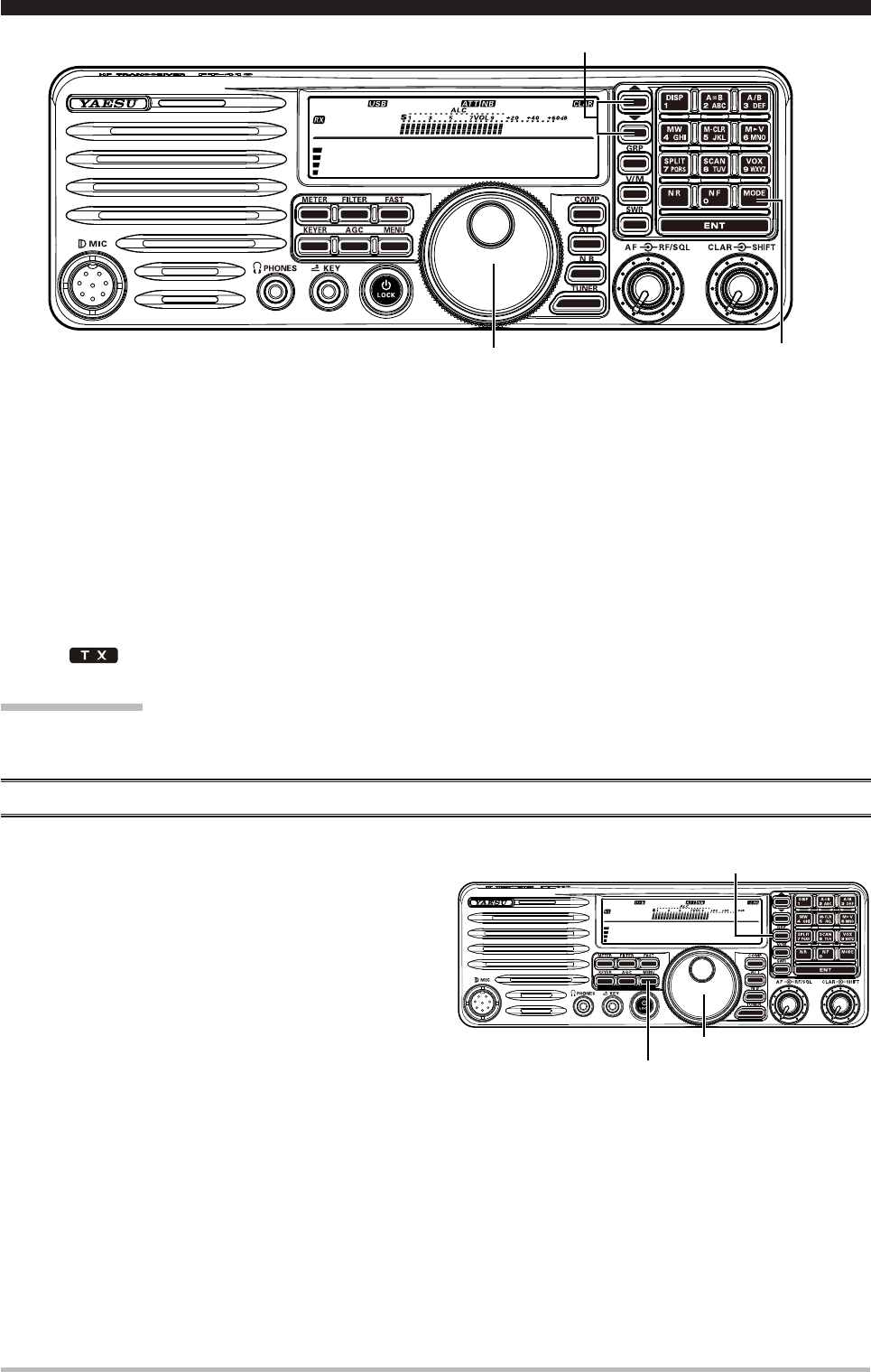
Att (AdjuSt the receiviNG SeNSitivity)
You may reduce the receiving signal strength to 20 dB when extremely strong local signals or high noise
degrade reception. You may optimize the characteristics of the receiver front-end, for best reception,
depending on the noise levels and the signal strengths.
Press the [ATT] button several times to set the desired
selection.
NoiSe blANKer (iNterfereNce rejectioN)
The FT-410 includes an effective Noise Blanker, which can signicantly reduce noise caused by automotive
ignition systems.
1. Press the [NB] button to activate the Noise Blanker.
2. Press the [NB] button again to disable the Noise
Blanker.
14.195.000
M-012
[MAIN DIAL] knob
[Power / Lock] button
14.195.000
M-012
[CLAR] knob
14.195.000
M-012
[ATT] button
Block Diagram
14.195.000
M-012
[NB] button
Block Diagram
Application for FCC / IC FCC ID: K6620621X50 IC: 511B-20621X50
Page 19FT-410 OperaTiOn Manual
cOnvenience FeaTures
AGc (tool for comfortAble ANd effective receptioN)
The AGC system is designed to help compensate for fading and other propagation effects, with
characteristics that can be of particular value on each operating mode. The basic objective of AGC is to
maintain a constant audio output level once a certain minimum threshold of signal strength is achieved.
Press the [AGC] button repeatedly to select the desired
receiver-recovery time constant. For most operations,
we recommend the “AUTO” mode.
14.195.000
M-012
[AGC] button
Block Diagram
Auto Sets the receiver-recovery time automati-
cally depending on the operating mode.
Fast Sets the receiver-recovery time to fast.
This mode is suitable for CW/DATA recep-
tion.
Slow Sets the receiver-recovery time to slow.
This mode is suitable for SSB/AM recep-
tion.
nOTe:
Normally, the “Auto” selection is satisfactory for most situations, but in the event of operation on a crowded
band where you wish to receive a weak signal, you may wish to change the setting (to FAST, for example).
A B C
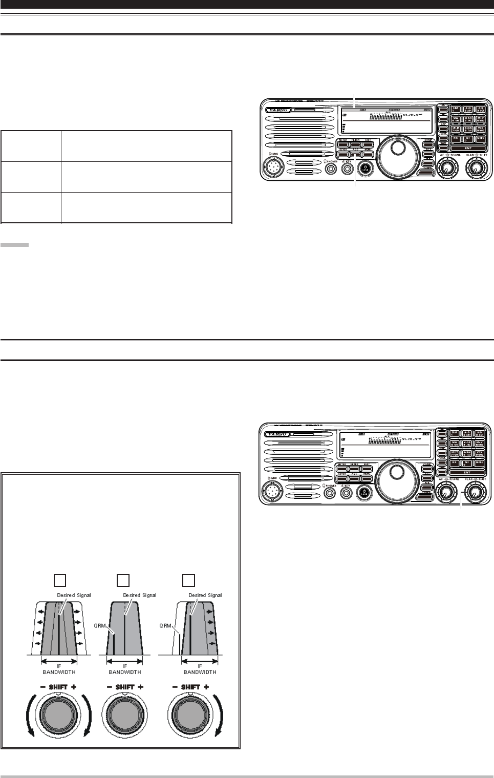
Shift (iNterfereNce rejectioN)
IF Shift allows you to vary the DSP lter passband higher or lower, without changing the pitch of the incoming
signal, so as to reduce or eliminate interference. Because the carrier tuning frequency is not varied, there is
no need to re-tune the operating frequency when eliminating the interference.
Rotate the [SHIFT] knob to the left or right to reduce
the interference.
Referring to Figure “A”, note the depiction of the IF DSP
filter as the thick line, with the [SHIFT] knob in the 12
o’clock position. In Figure “B”, an interfering signal has
appeared inside the original passband. In Figure “C”, you
can see the effect of rotating the [SHIFT] knob to reduce
the interference level by moving the lter passband so that
the interference is outside of the passband.
14.195.000
M-012
[SHIFT] knob
Application for FCC / IC FCC ID: K6620621X50 IC: 511B-20621X50

Page 20 FT-410 OperaTiOn Manual
cOnvenience FeaTures
rf GAiN
The RF Gain controls provide manual adjustment of the gain levels for the receiver RF and IF stages, to
compensate for noise and/or signal strength conditions at the moment.
The [RF/SQL] knob should, initially, be rotated to the
fully clockwise position. This is the point of maximum
sensitivity, and counter-clockwise rotation will gradually
reduce the system gain.
advice:
As the [RF/SQL] knob is rotated counterclockwise
to reduce the gain, the S-meter reading will rise.
Rotating the [RF/SQL] knob control to the fully
counter-clockwise position will essentially disable the receiver, as the gain will be greatly reduced. In this
case, the S-meter will appear to be “pegged”. (That is a full-scale reading).
14.195.000
M-012
[RF/SQL] knob
Application for FCC / IC FCC ID: K6620621X50 IC: 511B-20621X50
Page 21FT-410 OperaTiOn Manual
14.195.000
M-012
[MAIN DIAL] knob [MODE] button
[▼]/[▲] button
1. Press the []/[] buttons to select the operating band.
By pressing the []/[] buttons, the operating band will change as follows.
7
10 14 15 18 21 24.5 28 1.8 3.5 7 ......
2. Press the [MODE] buttons to select the LSB, USB or AM mode.
By convention, LSB is used in the 7 MHz and lower Amateur bands for SSB communication, and USB is
used on the 14 MHz and higher bands (the 10 MHz band is used for CW and data modes only).
3. Rotate the [MAIN DIAL] knob to adjust the operating frequency.
If you use the MH-31B8, you may adjust the operating frequency by the [UP]/[DWN] buttons on the
microphone.
4. Press the microphone’s PTT (Push To Talk) switch to begin transmission. Speak into the microphone in a
normal voice level.
The “ ” icon will appear in the display, conrming that transmission is in progress.
5. Release the PTT switch at the end of your transmission. The transceiver will return to the receive mode.
iMpOrTanT nOTe:
When performing tests, be sure to check the frequency before transmitting, to avoid interfering with others
who may already be using the frequency.
tx power AdjuStmeNt
Adjusting the TX output power:
1. Press the [MENU] button to enter the Menu mode.
The “Menu.” will appear on the display.
2. Rotate the [MAIN DIAL] knob to select the menu
item “RF PWR Set”.
3. Press the [GRP] button.
4. Rotate the [MAIN DIAL] knob to select the desired
power output.
5. Press the [GRP] button.
6. Press the [MENU] button to save the new setting
and return to normal operation.
14.195.000
M-012
[MAIN DIAL] knob
[MENU] button
[GRP] button
ssb/aM MOde TransMissiOn
Application for FCC / IC FCC ID: K6620621X50 IC: 511B-20621X50
Page 22 FT-410 OperaTiOn Manual
The powerful CW operating capabilities of the FT-410 include operation using both an electronic keyer
paddle and a “straight key” or emulation thereof, as is provided by a computer-based keying device.
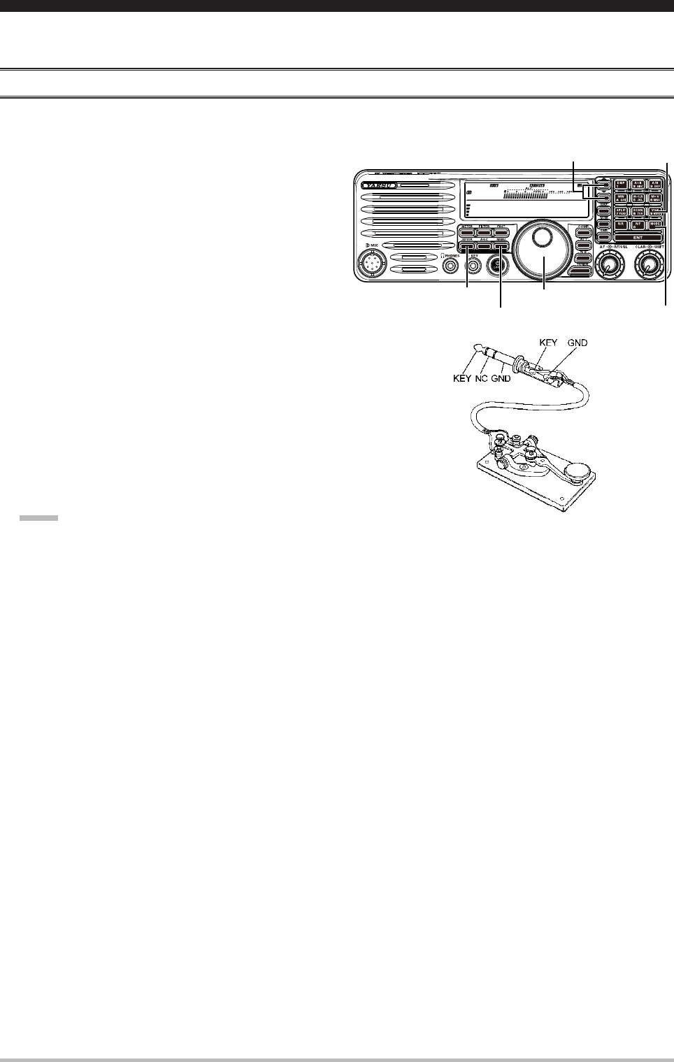
Setup for StrAiGht Key (ANd StrAiGht Key emulAtioN) operAtioN
Before starting, connect your key to the front panel KEY jack in the status that turned off the [Power / LOCK]
switch, and be sure the [KEYER] button is turned off for now.
1. Press the []/[] buttons to select the operating
band.
By pressing the []/[] buttons, the operating band
will change as follows.
7
10 14 15 18 21 24.5 28 1.8
3.5 7 ......
2. Press the [MODE] buttons to select the CW mode.
3. Rotate the [MAIN DIAL] knob to adjust the
operating frequency.
If you use the MH-31B8, you may adjust the
operating frequency by the [UP]/[DWN] buttons on
the microphone.
4. Press the [VOX] button to engage automatic
activation of the transmitter when you close the CW
key. The “BK” icon will appear in the display.
5. When you close your CW key, the transmitter will
automatically be activated, and the CW carrier
will be transmitted. When your release the key,
transmission will cease after a brief delay.
nOTe:
Do not use the plug except the 3.5-mm 3-pin type plug. If the plug in correct size is not used the radio
may be harmed or damaged.
14.195.000
M-012
[MAIN DIAL] knob
[MODE] button
[▼]/[▲] button
[KEYER] button
[MENU] button
[VOX] button
cW MOde OperaTiOn
Application for FCC / IC FCC ID: K6620621X50 IC: 511B-20621X50
Page 23FT-410 OperaTiOn Manual
cW MOde OperaTiOn
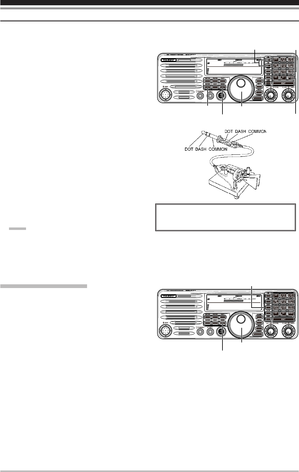
uSiNG the built-iN electroNic Keyer
Before starting, connect your keyer paddle to the front panel KEY jack in the status that turned off the [Power
/ LOCK] switch.
1. Press the []/[] buttons to select the operating
band.
By pressing the []/[] buttons, the operating
band will change as follows.
7
10 14 15 18 21 24.5 28 1.8
3.5 7 ......
2. Press the [MODE] buttons to select the CW mode.
3. Rotate the [MAIN DIAL] knob to adjust the
operating frequency.
If you use the MH-31B8, you may adjust the
operating frequency by the [UP]/[DWN] buttons on
the microphone.
4. Press the [VOX] button to engage automatic
activation of the transmitter when you close the CW
key. The “BK” icon will appear in the display.
5. Press the [KEYER] button to activate the built-in
Electronic Keyer.
6. When you press either the “Dot” or “Dash” side of
your paddle, the transmitter will automatically be
activated and the CW carrier will be transmitted.
When your release the paddle, transmission will
cease after a brief delay.
nOTe:
Do not use the plug except the 3.5-mm 3-pin type plug. If the plug in correct size is not used the radio
may be harmed or damaged.
You may enable the CW keying by the [UP]/[DWN] keys of
the MH-31B8 (while the built-in electronic keyer is engaged)
via menu item “CW Keyer”.
14.195.000
M-012
[MAIN DIAL] knob
[MODE] button
[▼]/[▲] button
[KEYER] button
[MENU] button
[VOX]
button
AdjuStiNG the Keyer Speed
1. Press the [MENU] button to enter the Menu mode.
The “Menu.” will appear on the display.
2. Rotate the [MAIN DIAL] knob to select the menu
item “CW Speed”.
3. Press the [GRP] button to enable adjustment of this
menu item.
4. Rotate the [MAIN DIAL] knob while pressing either
the “Dot” or “Dash” side of your paddle, so as to set
the desired keyer speed (4 - 60 wpm).
5. Press the [GRP] knob. The “Menu.” returns to
appear continuously.
6. Press the [MENU] button to save the new setting
and return to normal operation.
14.195.000
M-012
[MAIN DIAL] knob
[MENU] button
[GRP] button
Application for FCC / IC FCC ID: K6620621X50 IC: 511B-20621X50
Page 24 FT-410 OperaTiOn Manual
MeMOry OperaTiOn
coNveNieNt memory fuNctioNS
The FT-410 contains 120 regular memories, labeled “Mx001” through “Mx120”, one special programmed
limit memory pairs, labeled “ScanL/ScanU”, one Alaska Emergency Frequency Channel (5167.5 kHz), and
ve 60-meter (5 MHz) band channels (US version only). Each (except the Alaska Emergency Frequency
Channel and 60-meter Band channels, which are xed.) stores various settings, in addition to the frequency
and mode (See below). By default, the 120 regular memories are contained in one group; however, they can
be arranged in up to 5 separate groups, if desired.
Quick Point:
The FT-410’s memory channels store the following data:
Operating Frequency
Operating Mode
ATT status
IPO status
Repeater Shift Direction
CTCSS Tone Frequency
importANt Note:
On a rare occasion the memory data may be lost or corrupted due to static electricity, electrical noise or
erroneous operation. Parts changes or repairs may cause memory loss. Be sure to write down or record your
data so you will be able to restore it.
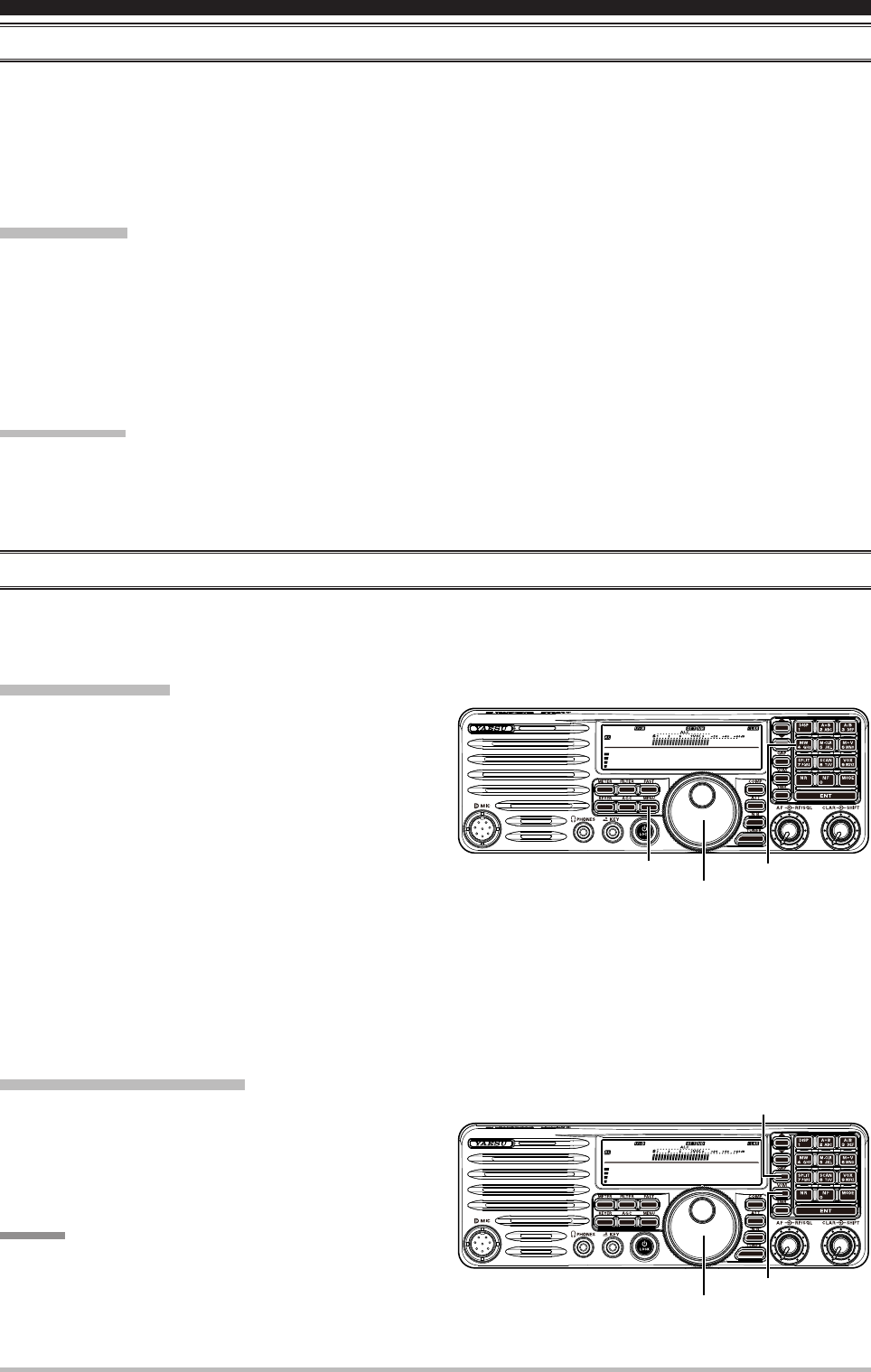
reGulAr memory operAtioN
The Regular Memory of the FT-410 allows storage and recall of up to 120 memories, each storing frequency,
mode, and a wide variety of status information detailed previously. Memories may be organized into as many
as 5 Memory Groups.
Memory Storage
1. In the VFO mode, select the desired frequency,
mode, and status the way you want to have it
stored.
2. Press the [M/W] button.
The blinking current memory channel number
will be shown on the display, and the contents of
the current memory channel will be shown on the
display.
If there is no action by you within 25 second from
releasing the [M/W] button the Memory Storage procedure is canceled.
The memory storage procedure is canceled unless you operate it within 25 seconds.
3. Rotate the [MAIN DIAL] knob to select the memory channel in which you wish to store the data.
4. Press and hold the [V/M] button for one second to store the frequency and other data into the selected
memory channel.
You may over write new data into a channel on which data is already stored.
Memory Channel Recall
1. Press the [V/M] button, if necessary, to enter the
Memory mode. A memory channel number will
appear in the display.
2. Rotate the [MAIN DIAL] knob to select the desired
memory channel.
Advice:
To work within a particular Memory Group, press the
[GRP] button. Then rotate the [MAIN DIAL] knob to
select the desired Memory Group.
14.195.000
M-012
[MAIN DIAL] knob
[MENU] button [M/W] button
14.195.000
M-012
[MAIN DIAL] knob
[GRP] button
[V/M] button
Application for FCC / IC FCC ID: K6620621X50 IC: 511B-20621X50
Page 25FT-410 OperaTiOn Manual
MeMOry OperaTiOn
reGulAr memory operAtioN
Erasing Memory Channel Data
1. Press the [V/M] button, if necessary, to enter the
Memory mode.
2. Rotate the [MAIN DIAL] knob to select the memory
channel that you would like to erase.
3. Press and hold the [M-CLR] button to erase the
contents of the selected memory channel. The
display will revert to memory channel 1.
Memory Tune Operation
You may freely tune off of any memory channel in the “Memory Tune” mode, this is similar to VFO operation.
So long as you do not over-write the contents of the current memory, Memory Tune operation will not alter
the contents of the memory channel.
1. Press the [V/M] button, if necessary, to enter the
Memory mode.
2. Rotate the [MAIN DIAL] knob. You will now observe
that the memory channel’s frequency is changing.
3. Press and hold the [V/M] button for one second.
During Memory Tune operation, you may change
operating modes, and engage and offset the
Clarier, if desired.
4. Press the [V/M] button momentarily to return to the
originally-memorized frequency of the current memory channel. One more press of the [V/M] button will
return you to VFO operation.
14.195.000
M-012
[MAIN DIAL] knob
[MENU] button [V/M] button
[M-CLR] button
14.195.000
M-012
[MAIN DIAL] knob
[V/M] button
Application for FCC / IC FCC ID: K6620621X50 IC: 511B-20621X50
Page 26 FT-410 OperaTiOn Manual
scanning OperaTiOn
You may scan either the VFO or the memories of the FT-410, and the radio will halt the scan on any station
with a signal strong enough to open the receiver’s squelch.
vfo ANd memory ScANNiNG
Preparation
When operating the Scanning feature, set the
configuration of the [RF/SQL] knob to “Squelch” via
the Menu Item “SQL/RF Gain”.
1. Press the [MENU] button to enter the Menu mode.
The “Menu.” will appear on the display.
2. Rotate the [MAIN DIAL] knob to select the menu
item “SQL/RF Gain”.
3. Press the [GRP] button to enable adjustment of this
menu item.
4. Rotate the [MAIN DIAL] knob to select “SQL” to assign the Squelch feature to the [RF/SQL] knob.
5. Press the [GRP] button. The “Menu.” returns to appear continuously.
6. Press the [MENU] button to save the new setting and return to normal operation.
VFO/Memory Scan
1. Rotate the [RF/SQL] knob just to the point where
the noise is silenced and the “RX” indicator on the
display turns off.
2. Press the [SCAN] button to initiate upward scanning
(toward higher frequencies or higher memory
channel numbers).
3. If you want to change direction of the scan while
it is underway, rotate the [MAIN DIAL] knob in the
opposite direction. You will see the scanner reverse
direction and scan down in frequency.
You may change the direction of the scanner by
pressing and holding the microphone’s [UP]/[DWN] key for one second, if you are using the MH-31B8
Hand Microphone.
4. In AM mode, when the scanner encounters a signal strong enough to open the squelch, the scanner will
halt for ve seconds, after which scanning will resume.
In the SSB/CW and SSB-based Data modes, when the scanner encounters a signal strong enough to
open the squelch, the scanner will step across the signal very slowly, giving you time to stop the scan, if
you like.
5. To stop the scanner, press the [SCAN] button or PTT switch.
advice:
You may select the manner in which the scanner resumes while it has paused on a signal, using Menu Item
“Scan Resume” The default “5sec” setting will cause the scanner to resume scanning after ve seconds; you
may change it, however, to resume only after the carrier has dropped out.
During Memory Group operation, only the channels within the current Memory Group will be scanned.
14.195.000
M-012
[MAIN DIAL] knob
[MENU] button [RF/SQL] knob
14.195.000
M-012
[MAIN DIAL] knob
[RF/SQL] knob
[SCAN] button
Application for FCC / IC FCC ID: K6620621X50 IC: 511B-20621X50

Page 27FT-410 OperaTiOn Manual
OperaTiOn On alasKa eMergency Frequency: 5167.5 KHz (u.s. versiOn Only)
Section 97.401(d) of the regulations governing amateur radio in the United States permit emergency amateur
communications on the spot frequency of 5167.5 kHz by stations in (or within 92.6 km of) the state of Alaska.
This frequency is only to be used when the immediate safety of human life and/or property are threatened,
and is never to be used for routine communications.
The FT-410 includes the capability for transmission and reception on 5167.5 kHz under such emergency
conditions.
Preparation
1. Press the [MENU] button to enter the Menu mode.
The “Menu.” will appear on the display.
2. Rotate the [MAIN DIAL] knob to select the menu
item “EMG”.
3. Press the [GRP] knob to enable adjustment of this
menu item.
4. Rotate the [MAIN DIAL] knob to select “ON”.
5. Press the [GRP] button. The “Menu.” returns to
appear continuously.
6. Press the [MENU] button to save the new setting and return to normal operation.
Operation
1. Press the [V/M] button, if necessary, to enter the Memory mode. A memory channel number will appear in
display.
2. Press the [GRP] button to select the emergency channel (“EMG”).
3. To exit from emergency channel and return to the VFO mode, just press the [V/M] button.
Note:
The receive-mode CLARIFIER functions normally while using this frequency, but variation of the transmit
frequency is not possible. Activation of “EMG” does not enable any other out-of-amateur-band capability
on the transceiver. The full specications of the FT-410 are not necessarily guaranteed on this frequency,
but power output and receiver sensitivity should be fully satisfactory for the purpose of emergency
communication.
In an emergency, note that a half-wave dipole cut for this frequency should be approximately 45’3”
on each leg (90’6” total length). Emergency operation on 5167.5 kHz is shared with the Alaska-Fixed
Service. This transceiver is not authorized for operation, under the FCC’s Part 87, for aeronautical
communications.
14.195.000
M-012
[MAIN DIAL] knob
[V/M] button
[MENU] button
Application for FCC / IC FCC ID: K6620621X50 IC: 511B-20621X50

Page 28 FT-410 OperaTiOn Manual
General
Rx Frequency Range: 30 kHz - 30 MHz (operating)
160 - 10 m (specied performance, Amateur bands only)
Tx Frequency Ranges: 160 - 10 m (Amateur bands only)
Frequency Stability: ±1 ppm/hour (@+25 °C, after warmup)
Operating Temperature Range: 14 °F ~ 122 °F (–10 °C ~ +50 °C)
Emission Modes: A1A (CW), A3E (AM), J3E (LSB, USB)
Frequency Steps: 10 Hz (SSB & CW), 1 kHz (AM)
Antenna Impedance: 50 Ohms, unbalanced
Power Consumption: Rx (signal present) 3.5 A
Tx (100 W) 23 A
Supply Voltage: DC 13.8 V ± 15%
Dimensions (WxHxD): 9’ x 3.3” x 8.5” (229 x 84 x 217 mm)
Weight (approx.): 8.8 lb (4.0 kg)
Transmitter
Power Output: 100 watts (25 watts AM carrier)
Modulation Types: J3E (SSB): Balanced,
A3E (AM): Low-Level (Early Stage),
Harmonic Radiation: Better than –50 dB
SSB Carrier Suppression: At least 50 dB below peak output
Undesired Sideband Suppression: At least 60 dB below peak output
Audio Response (SSB): Not more than –6 dB from 300 to 2200 Hz
Microphone Impedance: 600 Ohms (200 to 10 kOhms)
speciFicaTiOns
Application for FCC / IC FCC ID: K6620621X50 IC: 511B-20621X50

Page 29FT-410 OperaTiOn Manual
speciFicaTiOns
Receiver
Circuit Type: Double-conversion superheterodyne
Intermediate Frequencies: 67.899 MHz / 24 kHz
Sensitivity (IPO “OFF”, ATT: OFF): SSB/CW (2.4 kHz, 10 dB S+N/N)
0.25 µV (0.5 - 1.8 MHz)
0.25 µV (3.5 - 30 MHz)
0.20 µV (50 - 54 MHz)
AM (6 kHz, 10 dB S+N/N, 30 % modulation @400 Hz)
2.00 µV (1.8 - 2.0 MHz)
2.00 µV (3.5 - 30 MHz)
1.00 µV (50 - 54 MHz)
There is no specication in frequency ranges not listed.
Squelch Sensitivity: SSB/CW/AM
(IPO “OFF”, ATT: “OFF”) 2.50 µV (1.8 - 30 MHz)
1.00 µV (50 - 54 MHz)
There is no specication in frequency ranges not listed.
Selectivity (–6/–60 dB): Mode – 6 dB – 60 dB
SSB/CW (W) 2.0 kHz or better 4.5 kHz or less
CW (N) 300 Hz or better 1.2 kHz or less
AM 6 kHz or better 20 kHz or less
Image Rejection: 80 dB or better
IF Rejection: 80 dB or better
Maximum Audio Output: 10 W into 4 Ohms with 5% THD (EXT Speaker)
Audio Output Impedance: 4 to 16 Ohms (8 Ohms: nominal)
Specications are subject to change, in the interest of technical improvement, without notice or obligation,
and are guaranteed only within the amateur bands.
Application for FCC / IC FCC ID: K6620621X50 IC: 511B-20621X50

Page 30 FT-410 OperaTiOn Manual
Fcc nOTice
1. Changes or modifications to this device not expressly approved by YAESU MUSEN could void the user’s
authorization to operate this device.
2. This device complies with part 15 of the FCC Rules. Operation is subject to the following two conditions; (1)
this device may not cause harmful interference, and (2) this device must accept any interference including
interference that may cause undesired operation.
3. The scanning receiver in this equipment is incapable of tuning, or readily being altered, by the User to operate
within the frequency bands allocated to the Domestic public Cellular Telecommunications Service in Part 22.
DECLARATION BY MANUFACTURER
The scanner receiver is not a digital scanner and is incapable of being converted or modied into a digital scanner
receiver by any user.
WARNING: MODIFICATION OF THIS DEVICE TO RECEIVE CELLULAR RADIOTELEPHONE SERVICE SIGNALS
IS PROHIBITED UNDER FCC RULES AND FEDERAL LAW.
CAN ICES-3 (B) / NMB-3 (B)
This device complies with Industry Canada license-exempt RSS standard(s). Operation is subject to the following
two conditions: (1) this device may not cause interference, and (2) this device must accept any interference,
including interference that may cause undesired operation of the device.
Le présent appareil est conforme aux CNR d’Industrie Canada applicables aux appareils radio exempts de licence.
L’exploitation est autorisée aux deux conditions suivantes : (1) l’appareil ne doit pas produire de brouillage, et (2)
l'utilisateur de l’appareil doit accepter tout brouillage radioélectrique subi, même si le brouillage est susceptible d’en
compromettre le fonctionnement.
This equipment has been tested and found to comply with the limits for a Class B digital device, pursuant to Part
15 of the FCC Rules. These limits are designed to provide reasonable protection against harmful interference in a
residential installation. This equipment generates, uses and can radiate radio frequency energy and, if not installed
and used in accordance with the instructions, may cause harmful interference to radio communications. However,
there is no guarantee that interference will not occur in a particular installation.
If this equipment does cause harmful interference to radio or television reception, which can be determined by
turning the equipment off and on, the user is encouraged to try to correct the interference by one or more of the
following measures:
Increase the separation between the equipment and receiver.
Connect the equipment into an outlet on a circuit different from that to which the receiver is connected.
Consult the dealer or an experienced radio/TV technician for help.
Application for FCC / IC FCC ID: K6620621X50 IC: 511B-20621X50

Copyright 2015
YAESU MUSEN CO., LTD.
All rights reserved
No portion of this manual
may be reproduced without
the permission of
YAESU MUSEN CO., LTD.
Printed in Japan
Application for FCC / IC FCC ID: K6620621X50 IC: 511B-20621X50