Yaesu Musen 20621X50 HF Transceiver User Manual 05 User Manual
Yaesu Musen Co., Ltd. HF Transceiver 05 User Manual
Contents
- 1. Users Manual Part 1
- 2. Users Manual Part 2
Users Manual Part 1

HF/50 MHz Transceiver
FT-410
OperaTiOn Manual
YAESU MUSEN CO., LTD.
Tennozu Parkside Building
2-5-8 Higashi-Shinagawa, Shinagawa-ku, Tokyo 140-0002 Japan
YAESU USA
6125 Phyllis Drive, Cypress, CA 90630, U.S.A.
YAESU UK
Unit 12, Sun Valley Business Park, Winnall Close
Winchester, Hampshire, SO23 0LB, U.K.
Application for FCC / IC FCC ID: K6620621X50 IC: 511B-20621X50

Page 2 FT-410 OperaTiOn Manual
Table OF cOnTenTs
Front Panel Buttons and Knobs ........................ 3
Display Indications ............................................. 6
Rear Panel Jacks ................................................ 7
Supplied MH-31B8 Microphone ......................... 8
Accessories & Options ...................................... 9
Supplied Accessories ......................................................... 9
Available Options ............................................................... 9
Installation ......................................................... 10
Connection of Antenna and Power Supply....................... 10
About Coaxial Cable .........................................................11
Grounding ........................................................................ 12
Installation ......................................................... 12
VL-1000 Linear Amplier Interconnection ........................ 13
Interfacing to Other Linear Amplier ................................. 14
Easy Operation ................................................. 15
Receiving ................................................................... 15
Transmit ..................................................................... 15
Menu Operation ............................................................... 15
Resetting the Microprocessor .......................................... 16
Menu Mode Reset ..................................................... 16
All Reset .................................................................... 16
Receiving........................................................... 17
Tuning Steps .................................................................... 17
Change the Tuning Step of the [MAIN DIAL] Knob .... 17
About the [UP]/[DWN] buttons of the MH-31B8 ............... 17
Clarier ............................................................................. 18
DIAL Lock ......................................................................... 18
ATT (Adjust the Receiving Sensitivity) ............................. 18
Noise Blanker (Interference Rejection) ............................ 18
Convenience Features ..................................... 19
AGC (Tool for Comfortable and effective Reception) ...... 19
SHIFT (Interference Rejection) ........................................ 19
RF GAIN ........................................................................... 20
SSB/AM Mode Transmission ........................... 21
TX Power Adjustment ....................................................... 21
CW Mode Operation ......................................... 22
Setup for Straight Key
(and Straight Key emulation) Operation ....... 22
Using the Built-in Electronic Keyer ................................... 23
Adjusting the Keyer Speed ........................................ 23
Memory Operation ............................................ 24
Convenient Memory functions .......................................... 24
Quick Point: ............................................................... 24
Regular Memory Operation .............................................. 24
Memory Storage ........................................................ 24
Memory Channel Recall ............................................ 24
Regular Memory Operation .............................................. 25
Erasing Memory Channel Data .................................. 25
Memory Tune Operation ............................................ 25
Scanning Operation ......................................... 26
VFO and Memory Scanning ............................................. 26
Preparation ................................................................ 26
VFO/Memory Scan .................................................... 26
Operation on Alaska Emergency Frequency:
5167.5 kHz (U.S. Version Only) ........................ 27
Preparation ............................................................................. 27
Operation ................................................................... 27
Specications ................................................... 28
FCC Notice ........................................................ 30
Application for FCC / IC FCC ID: K6620621X50 IC: 511B-20621X50
Page 3FT-410 OperaTiOn Manual
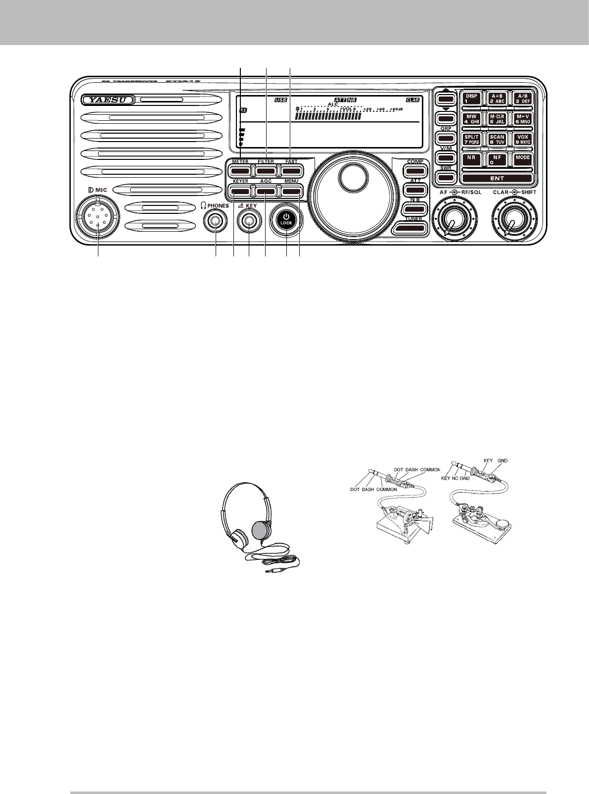
FrOnT panel buTTOns and KnObs
14.195.000
M-012
1 2 3
4 6 7 8 9 105
1. METER Button
Press this button to change the meter function in
the transmit mode as follows.
PO ALC SWR PO
PO: Indicates the average power output level.
ALC: Indicates the relative ALC voltage.
SWR: Indicates the Standing Wave Ratio
(Forward/Reected).
2. Filter Button
Press this button to change the lter.
3. FAST Button
Pressing this button will increase or decrease the
tuning rate of the [MAIN DIAL] knob.
4. MIC Jack
This 8-pin jack accepts input from a supplied
Hand Microphone.
5. PHONE Jack
A 3.5 mm, 3-contact jack
accepts either monaural or
stereo headphones with 2
or 3-contact plugs. When
a plug is inserted, the
loudspeaker is disabled.
Note:
When wearing headphones,
we recommend that you turn the AF GAIN levels
down to their lowest settings before turning
power on, to minimize the impact on your hearing
caused by audio “pops” during switch-on.
6. KEYER Button
This button toggles the internal CW keyer on and
off.
7. KEY Jack
This 3.5 mm, 3-contact jack accepts a CW key or
keyer paddles (for the built-in electronic keyer),
or output from an external electronic keyer.
Pinout is shown below. Key up is 5 volts, and key
down current is 0.5 mA.
Do not use the plug except the 3.5-mm 3-pin
type plug. If the plug in correct size is not used
the radio may be harmed or damaged.
If the Keyer plug is removed from the jack while
the FT-410 is in operation, the FT-410 may be
switched to the transmit mode.
Turn off the power of the FT-410 before
connecting or disconnecting the Keyer.
8. AGC Button
This button selects the AGC characteristics for
the receiver.
9. Power / LOCK Button
Press and hold in this button for one second to
turn the transceiver on or off. Press this button
the locking of the [MAIN DIAL] knob and some
switches, to prevent accidental frequency
changes.
10. MENU Button
Press this button, the Menu Item and a title for
the Menu Mode will appear in the display.
Application for FCC / IC FCC ID: K6620621X50 IC: 511B-20621X50
Page 4 FT-410 OperaTiOn Manual
14.195.000
M-012
16
11 12 13 1514
17 18 19 20 22
21 23
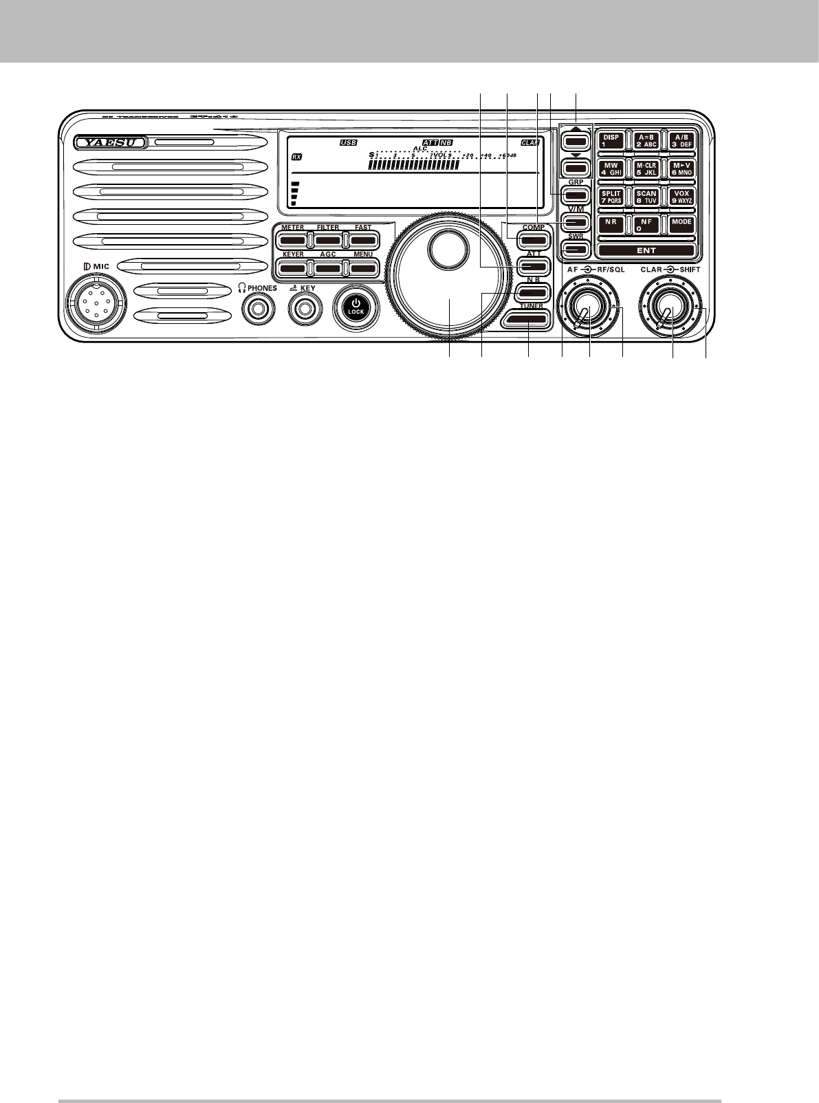
11. ATT Button
This button selects the ATT level.
12. COMP Button
This button turns the Speech Processor on and
off.
13. V/M Button
This button toggles frequency control between
VFO-A and the memory system. In memory
mode.
14. GRP Button
Pressing this button allows you to select a
memory group.
15. / Button
These buttons select the operating band.
16. MAIN DIAL Knob
This knob adjusts the operating frequency.
17. NB Button
This button turns the IF Noise Blanker on and off.
Press this button to reduce short-duration pulse
noise.
18. TUNER Button
Press this button momentarily to toggle the
Automatic Antenna Tuner on/off.
Press and hold in this button to begin the
automatic Tuning.
19. SWR Button
Indicates the Standing Wave Ratio (Forward/
Reected).
20. AF Knob
This knob sets the receiver’s audio volume level.
Typically, you will operate with this control set
between the 9 o’clock and 10 o’clock positions.
21. RF/SQL Knob
In the factory default, this knob adjusts the gain
of the receiver’s RF and IF stages. Using Menu
Item “SQL/RF Gain”, this knob may be changed
to function as a Squelch control, which may be
used to silence background noise when no signal
is present.
22. CLAR Knob
Pressing this button activates the Clarifier, to
allow temporarily offsetting the receive frequency.
23. SHIFT Knob
This knob shifts the IF DSP passband to reduce
an interfering signal which is inside the IF
passband.
FrOnT panel buTTOns and KnObs
Application for FCC / IC FCC ID: K6620621X50 IC: 511B-20621X50
Page 5FT-410 OperaTiOn Manual
14.195.000
M-012
26
35 36
27 282425
29
30
32
33
34
31
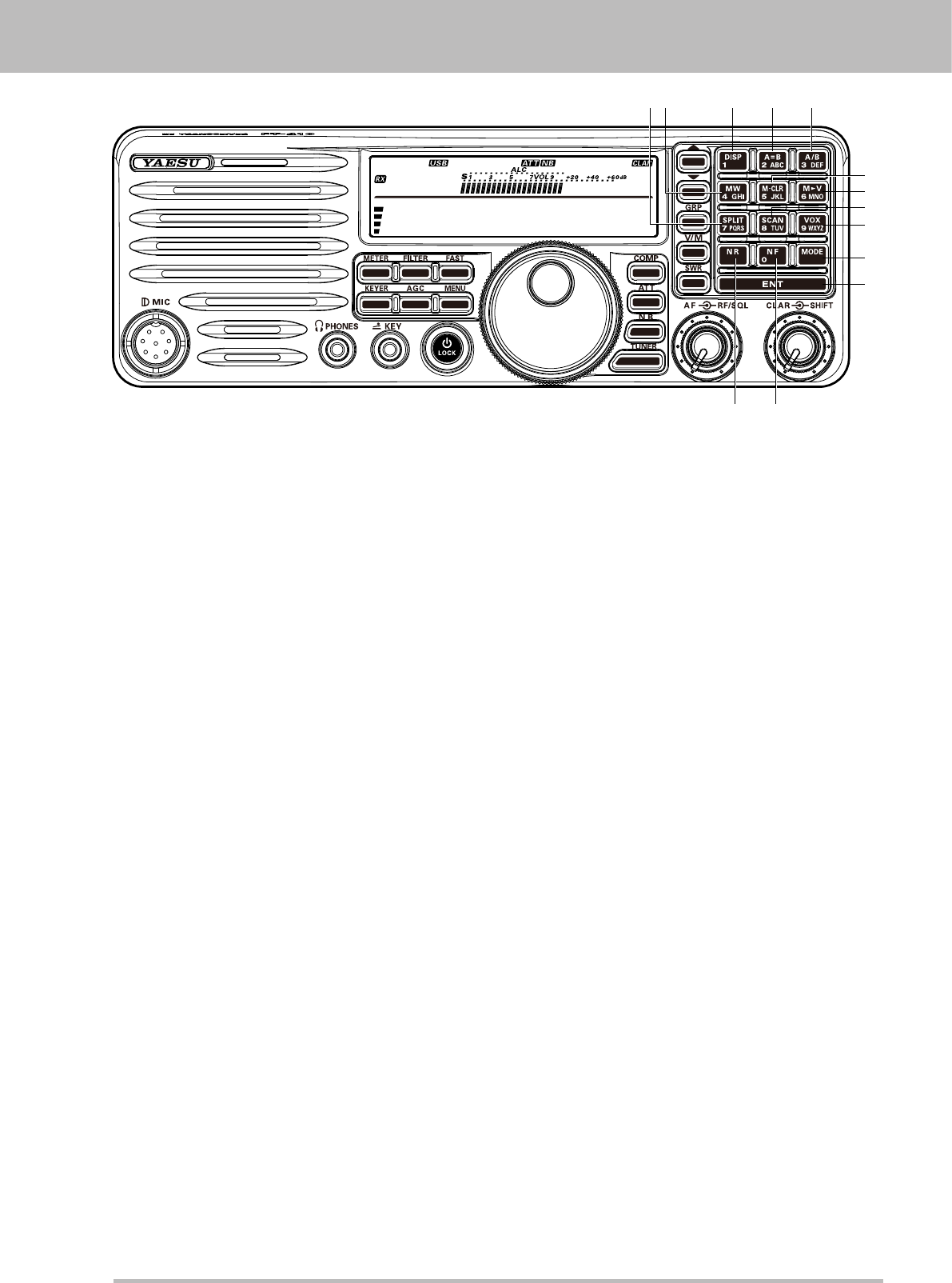
24. SPLIT Button
Press this button to activate split frequency
operation between VFO-A, used for reception
and VFO-B, used for transmission (or vice
versa).
25. MW Button
Pressing this button copies the current operating
data into the currently selected memory channel,
over-writing any previous data stored there.
26. DISP Button
27. A=B Button
Press this button momentarily to transfer data
from VFO-A frequency to VFO-B, overwriting the
previous contents in VFO-B. Use this key to set
both VFO-A and VFO-B to the same frequency
and mode.
28. A/B Button
This button toggles the frequency control
between VFO-A and VFO-B.
29. M-CLR Button
Press this button, a memory channel is cleared.
30. M
V Button
Press this button, a frequency and a mode of a
memory channel are forwarded to VFO.
31. SCAN Button
Press this button to initiate the upward scanning
of VFO frequencies or memory channels.
32. VOX Button
Press this button to activate the VOX (voice-
actuated transmitter switching) feature in the
SSB, and AM modes.
33. MODE Button
These buttons select the operating mode.
34. ENT Button
Press this button, setting is Oprating frequency.
35. NR Button
Press this button to activate Noise Reduction
operation
36. NF Button
Press this button to activate Notch Filter
operation.
FrOnT panel buTTOns and KnObs
Application for FCC / IC FCC ID: K6620621X50 IC: 511B-20621X50
Page 6 FT-410 OperaTiOn Manual
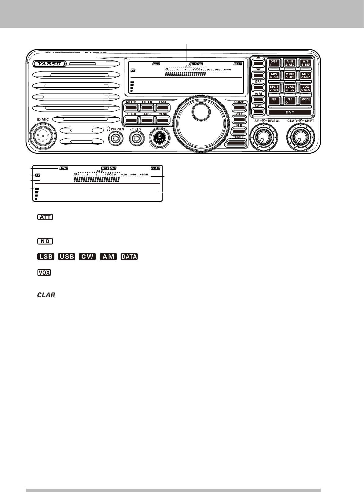
display indicaTiOns
14.195.000
M-012
Display
14.195.000
M-012
2
3
4
5
6
1
1. Information Display
: Indicates the RF attenuator status (“ON”
or “OFF”) selected for operation by the
[ATT] button.
: Indicates the Noise Blanker status (“ON”
or “OFF”).
////: Displays
the currently selected operating mode.
: This indicator appears whenever the VOX
(automatic voice-actuated transmitter
switching) circuit is activated.
: This indicator appears whenever the
Clarier function is activated.
2. TX / RX Display
TX: This indicator appears during transmission.
RX: This indicator appears whenever the
receiver squelch is open.
3. Indicates the operating band name, and
memory channel
When in VFO mode, the operating band name
(A or B) is displayed.While in memory mode, and
the memory channel number are displayed.
4. AF level indication
5. Meter
While receiving, the received signal strength is
displayed.
While transmitting, the meter displays PO,
ALC, or SWR (determined by the [METER/DIM]
button).
6. Frequency Display
The operating frequency is displayed.
Application for FCC / IC FCC ID: K6620621X50 IC: 511B-20621X50
Page 7FT-410 OperaTiOn Manual
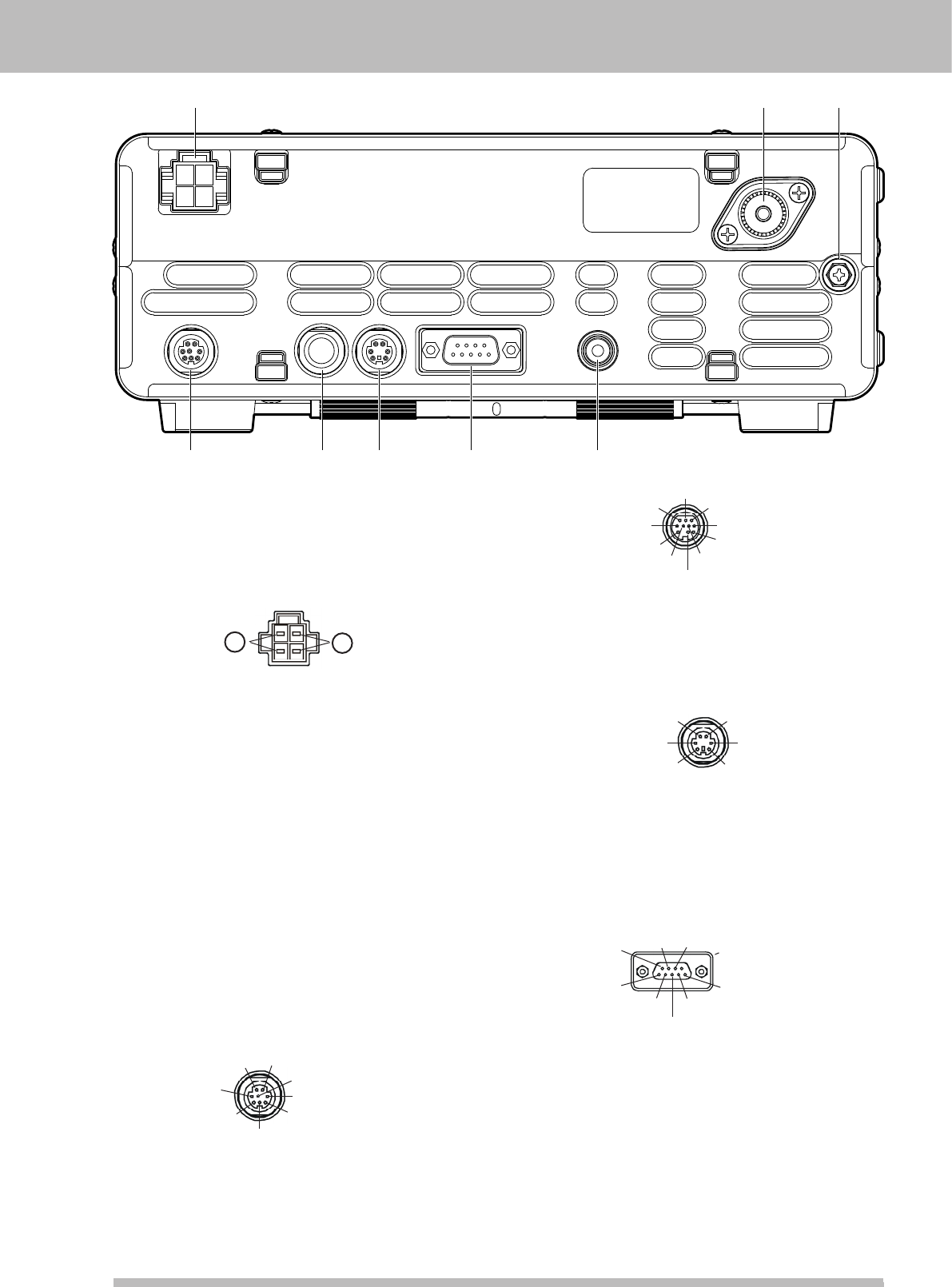
rear panel JacKs
1 2
87654
3
1. DC IN Jack
This is the DC power supply connection for
the transceiver. Use the supplied DC cable
to connect directly to the car battery or to a
DC power supply, which must be capable of
supplying at least 22 A @13.8 VDC.
(viewed from rear panel)
+
-
2. ANT Jack
Connect your antenna here, using a type-M (PL-
259) coaxial connector and 50 Ohm coaxial
feedline.
Warning!: High Power RF voltage is present
at the TX RF section of the transceiver while
transmitting. Absolutely! Do not touch the TX RF
section while transmitting.
3. GND Terminal
For safety and optimum performance, use this
terminal to connect the transceiver to a good
earth ground. Use a large diameter, short braided
cable for making ground connections. Refer to
page 12 for other notes about proper grounding.
4. TUNER Jack
This 8-pin jack is used for Connection to the FC-
40 External Automatic Antenna Tuner.
TXD
TX GND OUT
+13.8V OUT
GND
TUNER SENSE TX INH IN
RXD
RESET OUT (viewed from rear panel)
5. LINEAR Jack
This 10-pin output jack provides band selection
data, which may be used for control of the
optional VL-1000 Solid-State Linear Amplier.
BAND DATA-A (LSB)
TX GND OUT
+13.8V OUT
TXREQ IN
GND
BAND DATA-B BAND DATA-C
BAND DATA-D (MSB)
TX INH IN
EXT ALC IN (viewed from rear panel)
6. DATA Jack
This 6-pin input/output jack provides receiver
audio and squelch signals, and accepts transmit
(AFSK) audio and PTT control, from an external
packet TNC.
SQL OUT
FSK IN
GND
DATA IN
DATA PTT
DATA OUT
(viewed from rear panel)
7. CAT Jack
This 9-pin serial DB-9 jack allows external
computer control of the FT-410. Connect a
(straight) serial cable here and to the RS-
232C COM port on your personal computer (no
external interface is required).
CTS RTS
GND
SERIAL IN
SERIAL OUT
Connect to ,
Connect to ,
N/A
Connect to ,
(viewed from rear panel)
8. EXT SPKR Jack
This 3.5-mm, 2-pin jack provides variable audio
output for an external speaker. The audio output
impedance at this jack is 4 - 16 Ohms and the
level varies according to the setting of the front
panel’s [AF] knob. Inserting a plug into this jack
disables the internal loudspeaker.
Application for FCC / IC FCC ID: K6620621X50 IC: 511B-20621X50
Page 8 FT-410 OperaTiOn Manual
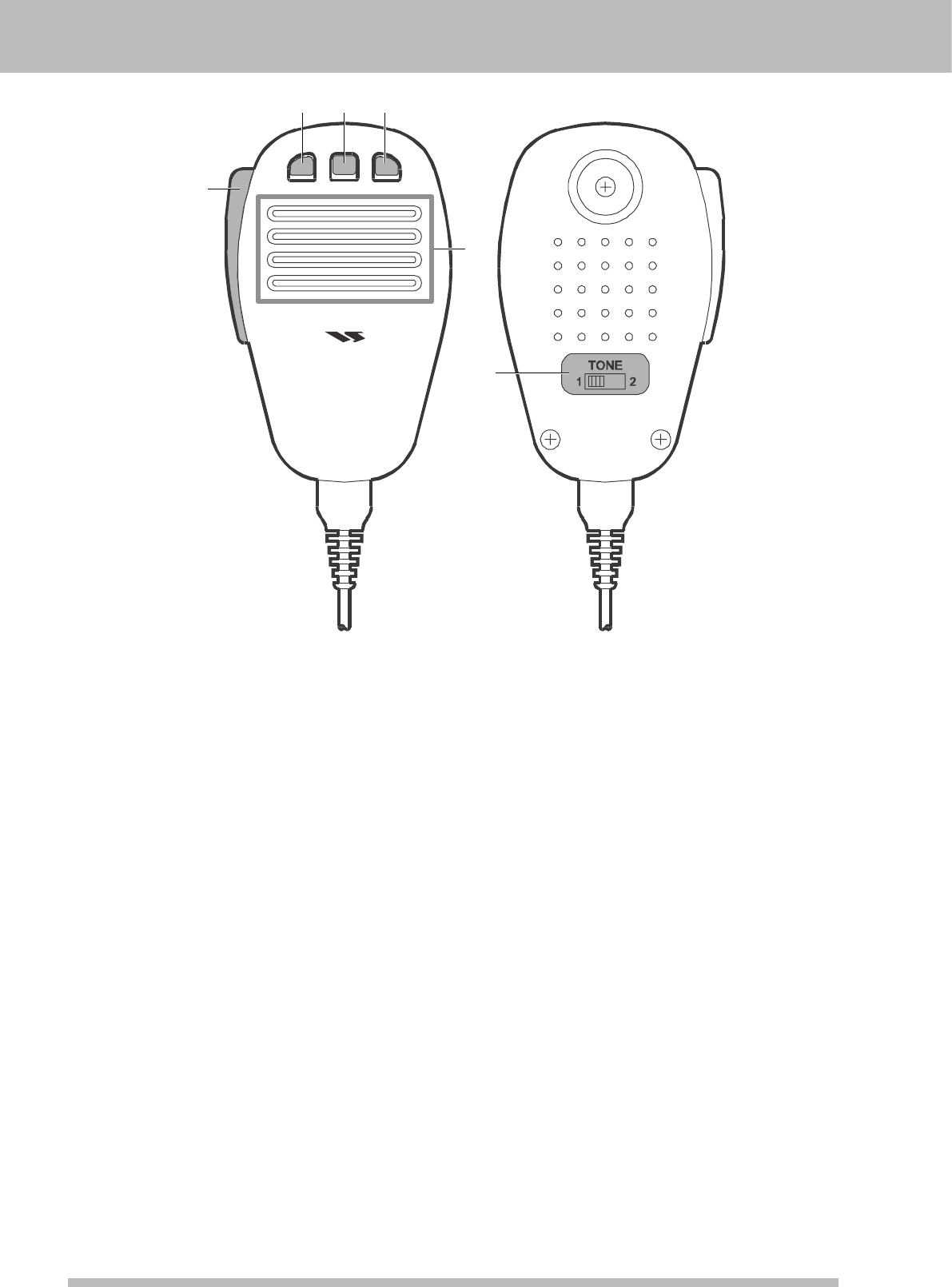
supplied MH-31b8 MicrOpHOne
DYNAMIC MICROPHONE
MH-31
DWN FST UP
23 4
5
1
6
1. PTT Switch
Press this Switch to transmit, and release it to
receive after your transmission is completed.
2. DWN Key
Press to tune down, hold to start scanning.
3. FST (FAST) Key
The FST Button on the transceiver should be set
for momentary operation.
4. UP Key
Press to tune up, hold to start scanning.
5. MIC
The microphone is located here. Speak into the
microphone in a normal voice level.
The microphone should be positioned within
2 inches (5 cm) from the mouth for optimum
performance.
6. TONE Switch
Position 1 provides flat-audio-characteristic
transmit audio.
Position 2 attenuates low audio tones, for
improved clarity in moderate band conditions, or
if you have a naturally deep voice.
Application for FCC / IC FCC ID: K6620621X50 IC: 511B-20621X50

Page 9FT-410 OperaTiOn Manual
accessOries & OpTiOns
Supplied AcceSSorieS
Hand Microphone (MH-31B8) 1 pc P/N: M3090086A
DC Power Cord with Fuse 1 pc P/N: T9025225
Fuse 1 pc P/N: Q0000074
Operation Manual 1 pc
Warranty Card 1 pc
AvAilAble optioNS
External Automatic Antenna Tuner (for Wire Antenna) FC-40
Active-Tuning Antenna System ATAS-25
Active-Tuning Antenna System ATAS-120A
Solid-State Linear Amplier/AC Power Supply VL-1000 / VP-1000
Band Data Cable (for VL-1000) CT-118
Desktop Microphone MD-100
Hand Microphone MH-31B8
Lightweight Stereo Headphone YH-77STA
Mobile Mounting Bracket MMB-90
Carrying Handle MHG-1
Linear Amplier Connection Cable SCU-28
Application for FCC / IC FCC ID: K6620621X50 IC: 511B-20621X50
Page 10 FT-410 OperaTiOn Manual
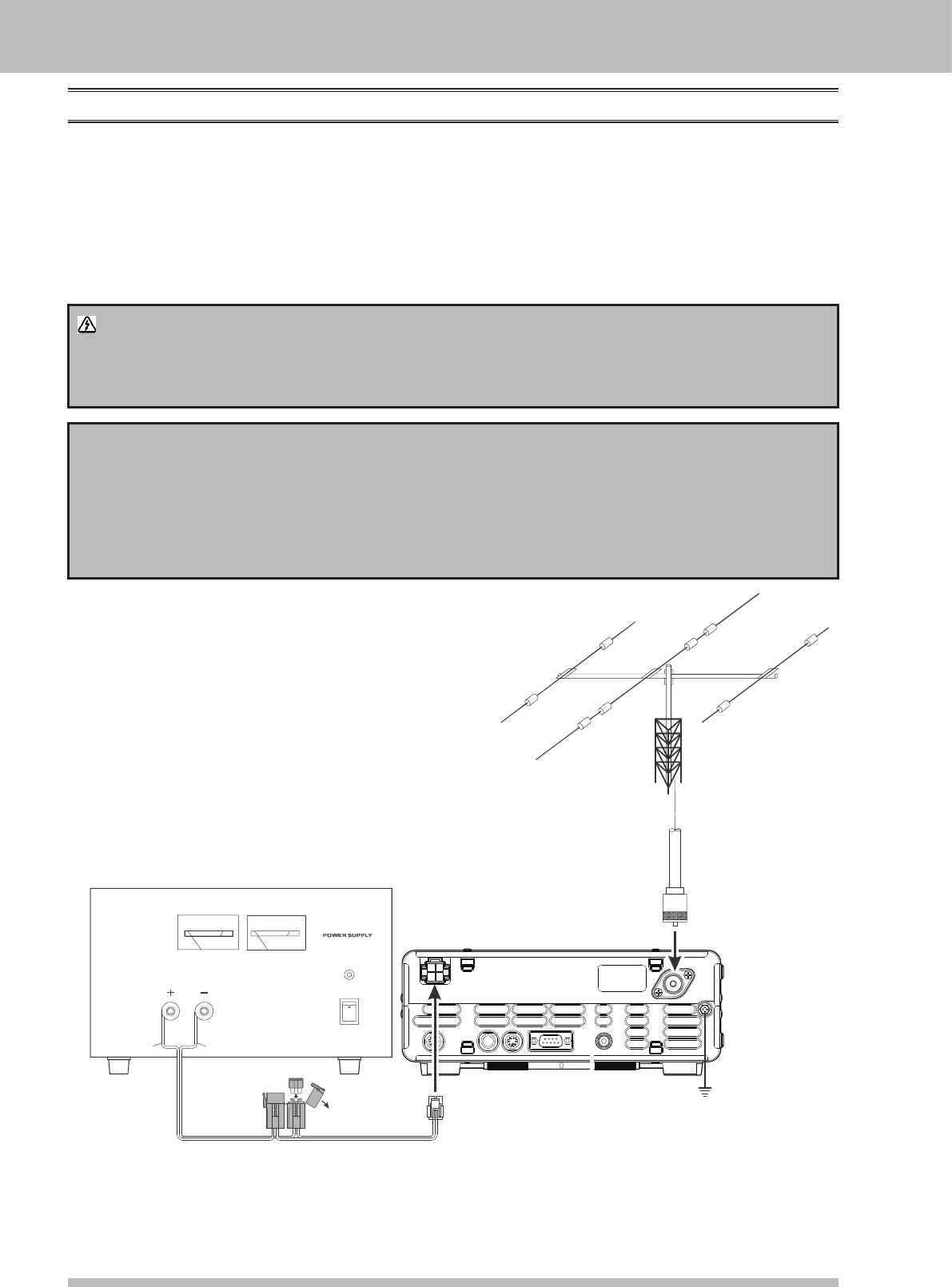
insTallaTiOn
coNNectioN of ANteNNA ANd power Supply
The FT-410 is designed for use with any antenna system providing a 50 Ohm resistive impedance at the
desired operating frequency. Every effort should be made to ensure the impedance of the antenna system is
as close as possible to the specied 50-Ohm value. Note that the “G5RV” type antenna does not provide 50-
Ohm impedance on all HF Amateur bands, and an external wide-range antenna coupler must be used with
this antenna type.
Any antenna to be used with the FT-410 must, ultimately, be fed with 50 Ohm coaxial cable. Therefore, when
using a “balanced” antenna such as a dipole, remember that a balun or other matching/balancing device
must be used to ensure proper antenna performance.
Warning!
The 100V RF voltage (@100 W/50 Ω) is applied to the TX RF section of the transciver while
transmitting.
Do not touch the TX RF section absolutely while transmitting.
CAUTION
Permanent damage can result if improper supply voltage, or reverse-polarity voltage, is applied
to the FT-410. The Limited Warranty on this transceiver does not cover damage caused by
application of AC voltage, reversed polarity DC, or DC voltage outside the specied range of
13.8V ±15%.
When replacing fuses, be certain to use a fuse of the proper rating. The FT-410 requires a 25A
fast-blow fuse.
AC Power Supply
FT-410
A
0 5 20 30 40
PO WE R
ON
OF F
RED BLACK
FUSE: 25A
V
0 5 10 15 20
ANNTENA
Application for FCC / IC FCC ID: K6620621X50 IC: 511B-20621X50
Page 11FT-410 OperaTiOn Manual
insTallaTiOn
CAUTION
Do not position this apparatus in a location with direct exposure to sunshine.
Do not position this apparatus in a location exposed to dust and/or high humidity.
Do not expose the apparatus to dripping or splashing. Do not put objects with liquids on the
apparatus.
Ensure adequate ventilation around this apparatus, so as to prevent heat build-up and
possible reduction of performance due to high heat.
Do not install this apparatus in a mechanically-unstable location, or where objects may fall
onto this product from above.
To minimize the possibility of interference to home entertainment devices, take all
precautionary steps including separation of TV/FM antennas from Amateur transmitting
antennas to the greatest extent possible, and keep transmitting coaxial cables separated
from cables connected to home entertainment devices.
Be absolutely certain to install your transmitting antenna(s) such that they cannot possibly
come in contact with TV/FM radio or other antennas, nor with outside power or telephone
lines.
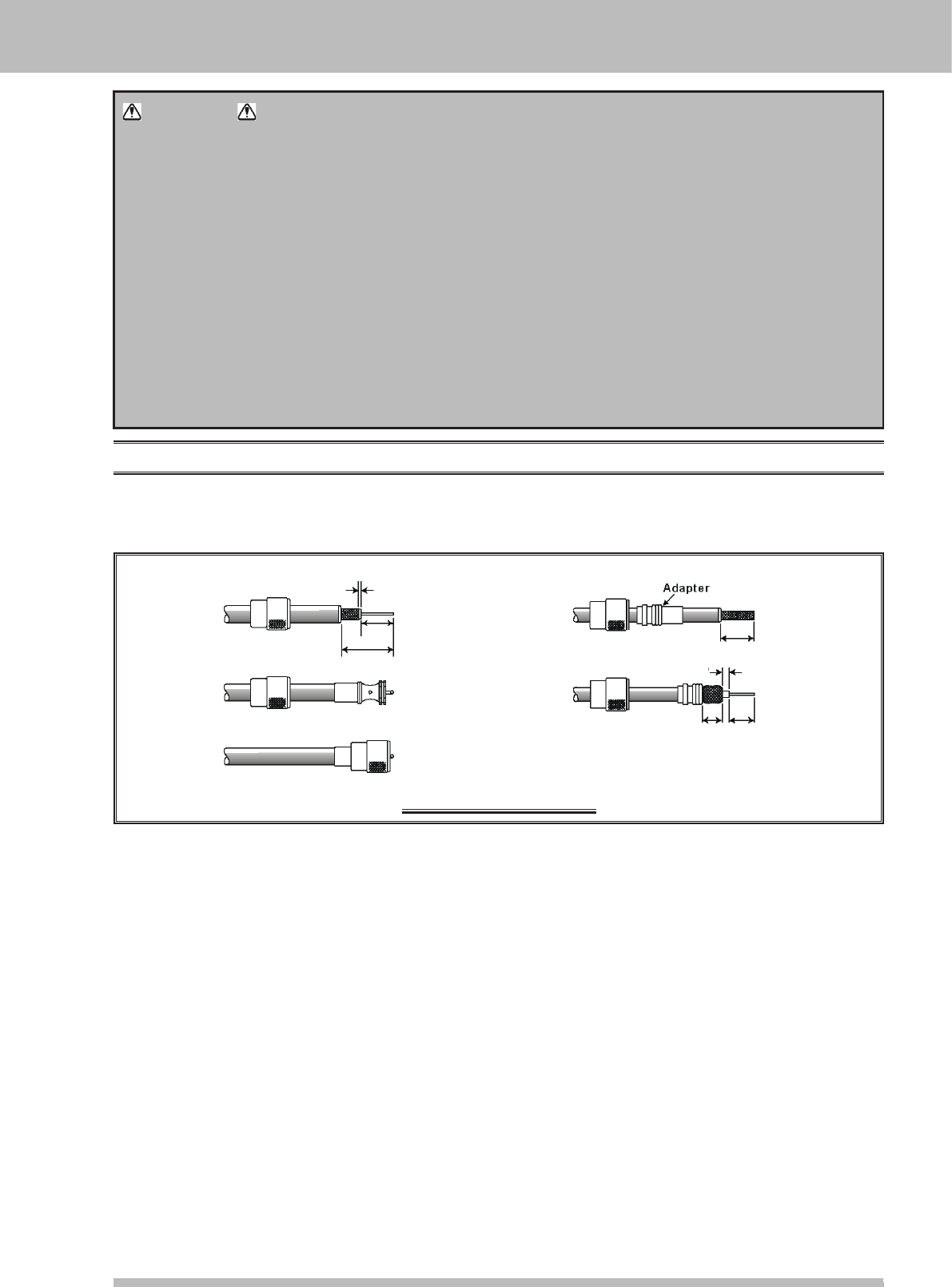
About coAxiAl cAble
Use high-quality 50-Ohm coaxial cable for the lead-in to your FT-410 transceiver. All efforts at providing an
efcient antenna system will be wasted if poor quality, lossy coaxial cable is used. This transceiver utilizes
standard “M” (“PL-259”) type connector.
typicAl pl-259 iNStAllAtioN
20 mm
20 mm
30 mm
3 mm
10 mm 15 mm
2 mm
Application for FCC / IC FCC ID: K6620621X50 IC: 511B-20621X50
Page 12 FT-410 OperaTiOn Manual
GrouNdiNG
The FT-410 transceiver, like any other HF communications apparatus, requires an effective ground system
for maximum electrical safety and best communications effectiveness. A good ground system can contribute
to station efciency in a number of ways:
It can minimize the possibility of electrical shock to the operator.
It can minimize RF currents owing on the shield of the coaxial cable and the chassis of the transceiv-
er. Such currents may lead to radiation, which can cause interference to home entertainment devices
or laboratory test equipment.
It can minimize the possibility of erratic transceiver/accessory operation caused by RF feedback and/or
improper current ow through logic devices.
An effective earth ground system may take several forms. For a more complete discussion, see an
appropriate RF engineering text. The information below is intended only as a guideline.
Typically, the ground connection consists of one or more copper-clad steel rods, driven into the ground. If
multiple ground rods are used, they should be positioned in a “V” conguration, and bonded together at the
apex of the “V” which is nearest the station location. Use a heavy, braided cable (such as the discarded
shield from type RG-213 coaxial cable) and strong cable clamps to secure the braided cable(s) to the ground
rods. Be sure to weatherproof the connections to ensure many years of reliable service. Use the same type
of heavy, braided cable for the connections to the station ground bus (described below).
Inside of the station, a common ground bus consisting of a copper pipe of at least 25 mm (1”) diameter
should be used. An alternative station ground bus may consist of a wide copper plate (single-sided circuit
board material is ideal) secured to the bottom of the operating desk. Grounding connections from individual
devices such as transceivers, power supplies, and data communications devices (TNCs, etc.) should be
made directly to the ground bus using a heavy, braided cable.
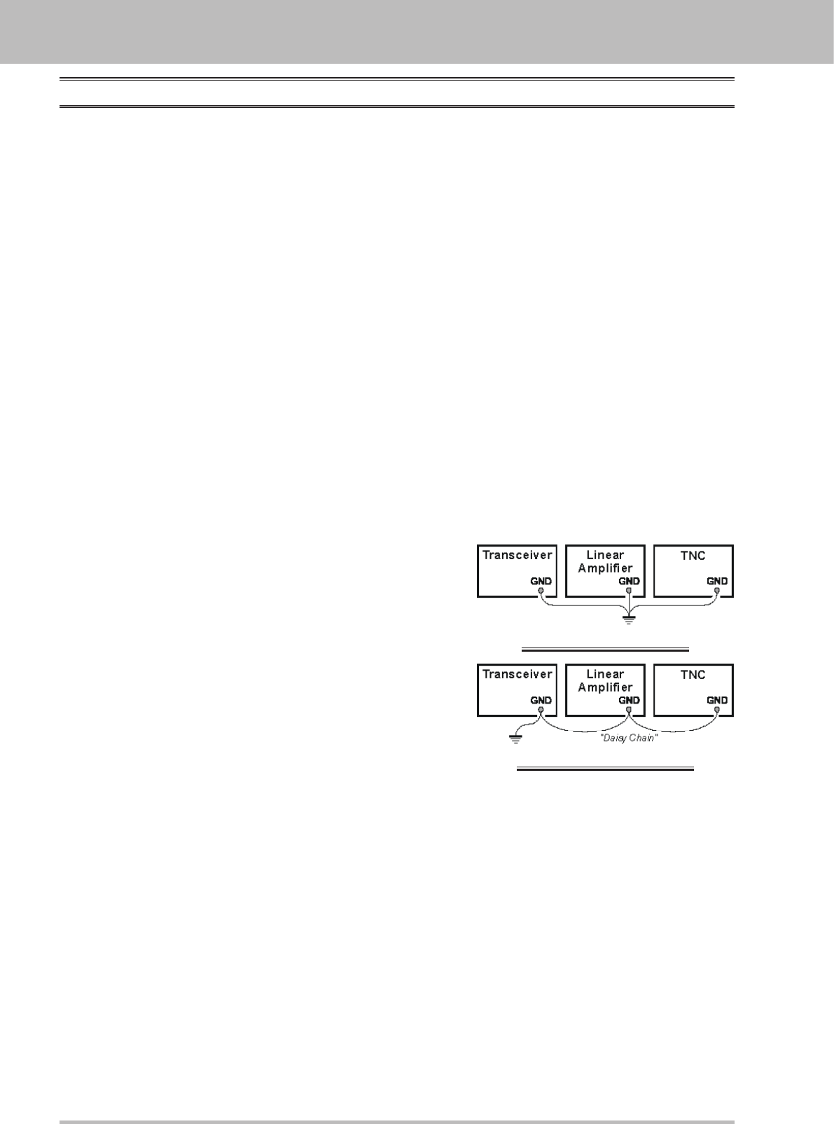
Do not make ground connections from one electrical device to
another, and thence to the ground bus. This so-called “Daisy-
Chain” grounding technique may nullify any attempt at effective
radio frequency grounding. See the drawing at the right for
examples of proper grounding techniques.
Inspect the ground system - inside the station as well as outside
- on a regular basis so as to ensure maximum performance and
safety.
Besides following the above guidelines carefully, note that
household or industrial gas lines must never be used in an
attempt to establish an electrical ground. Cold water pipes may,
in some instances, help in the grounding effort, but gas lines
represent a signicant explosion hazard, and must never be used.
insTallaTiOn
proper GrouNd coNNectioN
improper GrouNd coNNectioN
Application for FCC / IC FCC ID: K6620621X50 IC: 511B-20621X50
Page 13FT-410 OperaTiOn Manual
insTallaTiOn
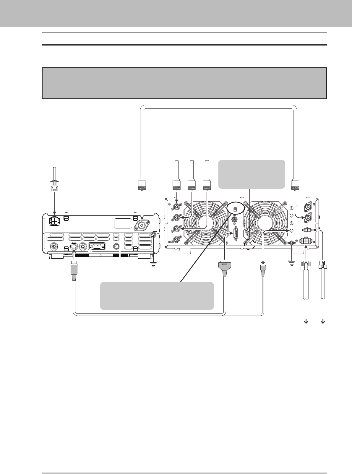
vl-1000 liNeAr Amplifier iNtercoNNectioN
Be sure that both the FT-410 and VL-1000 are turned off, then follow the installation recommendations
contained in the illustration.
Note
Please refer to the VL-1000 Operating Manual for details regarding amplier operation.
Please do not attempt to connect or disconnect coaxial cables when your hands are wet.
ANT
ANT 1
ANT 2
ANT 3
ANT 4
REMOTE
ON
OFF
BAND DATA 1
BAND DATA 2
GND
ALC 2
ALC 1
PTT 2
PTT 1 INPUT 1
INPUT 2
CONTROL
DC48V IN
ANT
INPUT
DC 13.8
V
ANT 1
HF Vertical Antenna
HF Dipole Antenna
HF Beam Antenna
ANT 2
ANT 3
INPUT 2
BAND-DATA 2
GND
GND
DC 48V IN
CONTROL
ALC 2
CT-118 CONNECTION CABLE
(Option)
ANTENNA CABLE (Not Supplied )
VP-1000
VP-1000
LINEAR
To link the FT-410 and VL-1000
Power switches, set the VL-1000 RE-
MOTE switch to the “ON” position.
Set the front panel’s
INPUT switch to the
“INPUT2”.
Application for FCC / IC FCC ID: K6620621X50 IC: 511B-20621X50
Page 14 FT-410 OperaTiOn Manual
insTallaTiOn
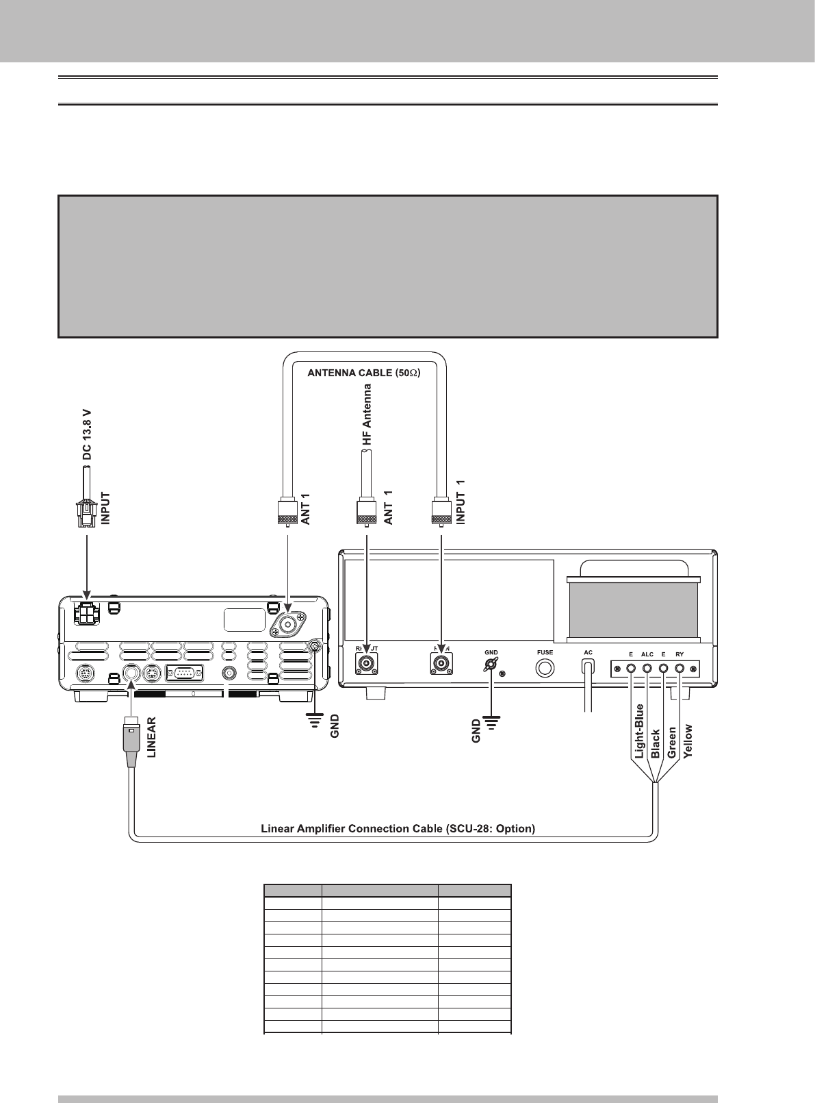
iNterfAciNG to other liNeAr Amplifier
The T/R control line is a transistor “open collector” circuit, capable of handling positive amplier relay coil
voltages of up to +50V DC and current of up to 400 mA. If you plan on using multiple linear ampliers for
different bands, you must provide external band-switching of the “Lin Tx” relay control line from the “TX GND
OUT” line at the LINEAR jack.
Important Note!
Do not exceed the maximum voltage or current ratings for the “TX GND OUT” line at the LINEAR jack.
This line is not compatible with negative DC voltages, nor AC voltages of any magnitude.
Most amplier control relay systems require only low DC voltage/current switching capability (typically,
+12V DC at 25 ~ 75 mA), and the switching transistor in the FT-410 will easily accommodate such
ampliers.
Wire Color
Orange
Yellow
Green
Red
White
Blue
Violet
Brown
Black
Gray
Light Blue
LINEA Jack (Pin Number)
1
2
3
4
5
6
7
8
9
10
Case
Function
+13.8 V
TX GND OUT
GND
BAND DATA A
BAND DATA B
BAND DATA C
BAND DATA D
TX INH
EXT ALC IN
TX REQ IN
Shield
Linear Amplier Connection Cable (SCU-28)
Color Code Information
Application for FCC / IC FCC ID: K6620621X50 IC: 511B-20621X50
Page 15FT-410 OperaTiOn Manual
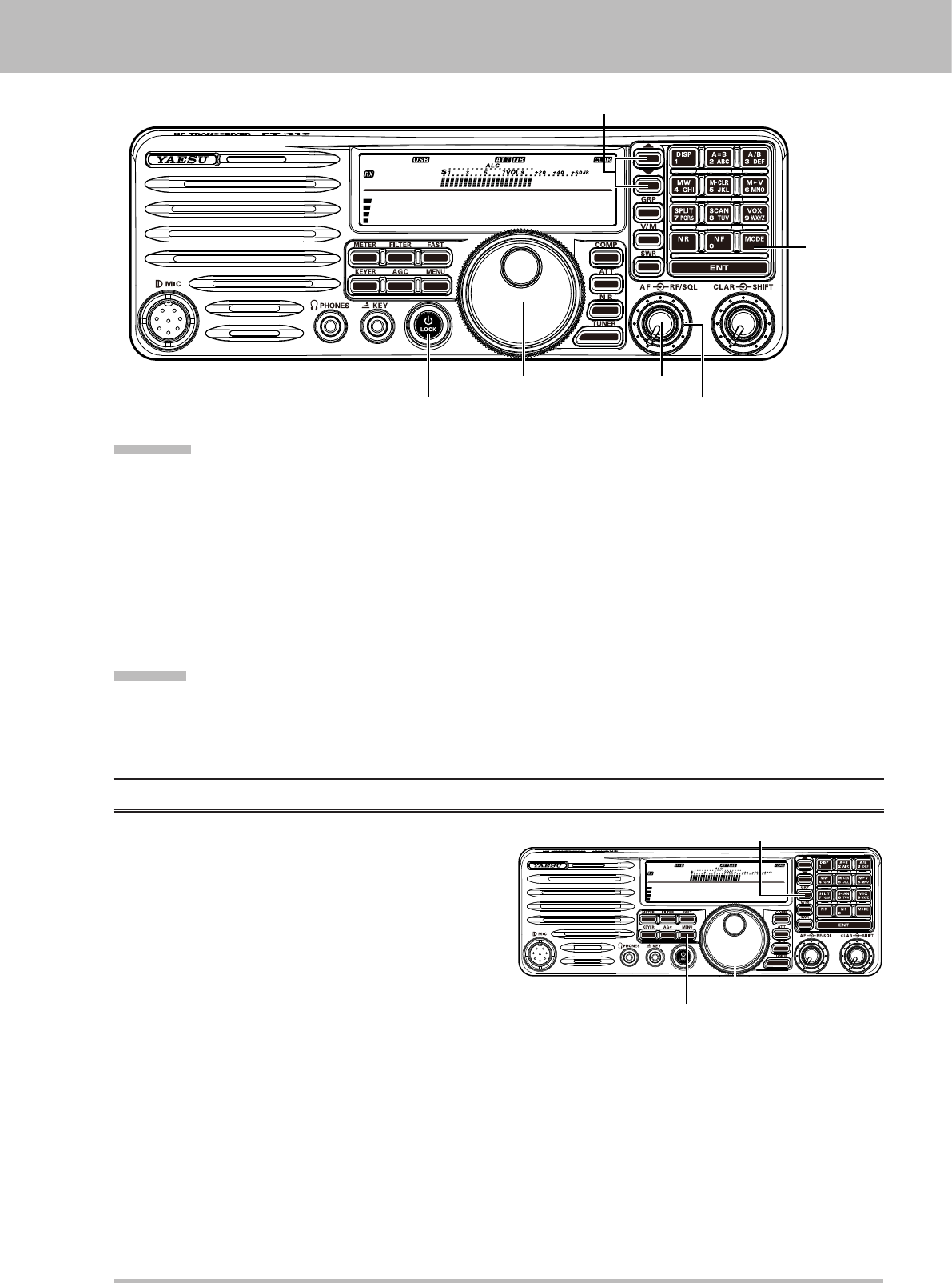
easy OperaTiOn
14.195.000
M-012
[Power / LOCK] button
[MAIN DIAL] knob
[MODE]
button
[AF] knob
[RF/SQL] knob
[▼]/[▲] button
receiviNG
1. Connect your antenna to the ANT jack on the rear panel.
2. Connect the after-market DC power supply (or car battery) using the supplied DC power cable, and set the
POWER switch of the DC power supply to on.
3. Press and hold in the [Power / LOCK] switch for one second to turn the transceiver on.
4. Rotate the [RF/SQL] knob to the fully clockwise position.
5. Rotate the [AF] knob to set a comfortable audio level on incoming signals or noise. Clockwise rotation of
the [AF] knob increases the volume level.
6. Press the []/[] button to select the amateur band which you wish to begin operating.
7. Press the [MODE] button to select the desired operating mode.
8. Rotate the [MAIN DIAL] knob to set the desired frequency.
trANSmit
1. Connect the Microphone to the MIC jack on the front panel.
2. To transmit, press the microphone’s PTT (Push To Talk) switch, speak into the microphone in a normal
voice level.
3.
Release the PTT switch to return to the receive mode.
meNu operAtioN
The Menu System allows you to customize a wide
variety of transceiver performance aspects and
operating characteristics. After you have initially
customized the various Menu procedures, you will
nd that you will not have to resort to them frequently
during everyday operation.
1. Press the [MENU] button to enter the Menu Mode.
The “Menu.” will appear on the display.
2. Rotate the [MAIN DIAL] knob to select the Menu
Item to be adjusted.
3. Press the [GRP] button to enable adjustment of the selected Menu Item. The “>>” will appear on the
display.
4. Rotate the [MAIN DIAL] knob to adjust or select the parameter to be changed.
5. Press the [GRP] button to save the selection. The icon appears continuously.
6. Press the [MENU] button to return to normal operation.
14.195.000
M-012
[MENU] button
[MAIN DIAL] knob
[GRP] button
Application for FCC / IC FCC ID: K6620621X50 IC: 511B-20621X50