Yaesu Musen 20651X50 HF/50 MHz Amateur Transceiver User Manual FT 891 User Manual 1
Yaesu Musen Co., Ltd. HF/50 MHz Amateur Transceiver FT 891 User Manual 1
Contents
- 1. Users Manual
- 2. Users Manaul
Users Manaul
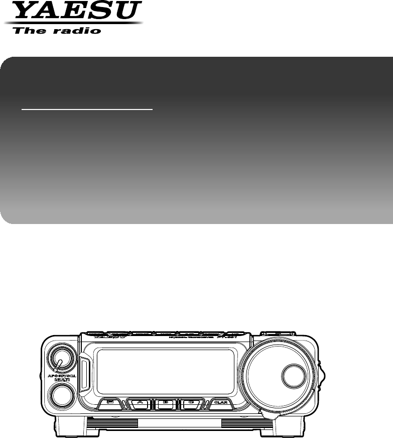
HF/50 MHz TRANSCEIVER
FT-891
Operating Manual
Application for FCC / IC
FCC ID: K6620651X50 / IC: 511B-20651X50

2
Contents
FT-891 Operating Manual
Introduction ............................................................... 3
Accessories & Options ............................................ 4
Supplied Accessories .............................................. 4
Optional Accessories ............................................... 4
Installation ................................................................. 5
Connecting the Microphone ..................................... 5
Power connection .................................................... 6
Grounding ................................................................ 7
Mobile Station Grounding ..................................... 7
Base Station Earth Grounding .............................. 8
RF FIELD EXPOSURE ............................................ 9
Front Panel Controls & Switches .......................... 10
Rear Panel Connectors .......................................... 12
Basic Operation ...................................................... 14
Turning the Transceiver ON and OFF ................... 14
Operating Band Selection ...................................... 14
Mode Selection ...................................................... 14
Adjusting the Audio Volume Level ......................... 14
Adjusting the RF Gain and Squelch ...................... 15
Setting the Operating Frequency ........................... 15
Operation on 60-Meter (5 MHz) Band
(U.S. Version Only) ......... 16
Lock Feature .......................................................... 16
Clarifier (Receiver Incremental Tuning) ................. 17
Advanced Operation .............................................. 18
IF SHIFT ................................................................ 18
AGC (Automatic Gain Control) .............................. 18
Noise Blanker ........................................................ 19
IPO (Intercept Point Optimization) ......................... 19
ATT (Attenuator) .................................................... 20
DSP Noise Reduction (DNR) ................................. 20
Notch Filter ............................................................ 21
Memory Operation .................................................. 22
QMB (Quick Memory Bank) Channels .................. 22
QMB Channel Storage........................................ 22
QMB Channel Recall .......................................... 22
Memory Operation on
“Regular” Memory Channels .... 23
Normal Memory Storage ....................................... 23
Memory Channel Recall ........................................ 23
Miscellaneous Settings .......................................... 24
Display Contrast .................................................... 24
Display Dimmer ..................................................... 24
Reset Procedure ..................................................... 25
Microprocessor Resetting ................................... 25
Setup (Menu) Mode ................................................ 26
Specifications ......................................................... 30
Application for FCC / IC
FCC ID: K6620651X50 / IC: 511B-20651X50

3FT-891 Operating Manual
Introduction
The FT-891 is a rugged, innovative multiband, multimode mobile/portable transceiver for
the amateur radio MF/HF/50 MHz bands. Providing coverage of the 160 - 6 meter bands,
the FT-891 includes operation on the SSB, CW, AM and FM modes, yielding the most
comprehensive performance package available for mobile and field operation.
Engineered for high performance, the FT-891 provides 100 watts power output on the 160
through 6 meter bands.
The multi-function Liquid-Crystal Display includes attractive backlighting.
The display includes bar-graph indication of power output, ALC voltage, SWR, modulation
level, and/or signal strength. Also included are a number of operating status icons, as well
as the function displays for the three operating function keys ([A], [B], and [C]).
Among the advanced features of the FT-891 are many incorporated only in large bases-
tation transceivers. These include Dual VFOs; Split-Frequency operation; Digital Signal
Processing (Bandpass Filtering, Noise Reduction, Auto-Notch, and Microphone Equaliz-
er);
IF Shift; Clarifier (“R.I.T.”); IF Noise Blanker; AGC Fast/Middle/Slow/Auto selection; RF
Gain and Squelch control; IPO (Intercept Point Optimization) and a receiver front-end
Attenuator; AM Broadcast reception; VOX; Built-in Electronic Keyer with Memories and a
Beacon mode; Adjustable CW Pitch; Automatic FM Repeater Shift (ARS); Built-in CTCSS
Encoder/Decoders;
Spectrum Scope; 200 Memories plus Home Channels and Band-limiting Memories;
Alpha-Numeric Labeling of Memories; Automatic Power-Off (APO) and Time-Out Timer
(TOT) functions; Computer Interface capability; and Cloning capability.
We urge you to read this manual in its entirety, so as to gain a full understanding of the
amazing capability of the exciting new FT-891 Transceiver.
Application for FCC / IC
FCC ID: K6620651X50 / IC: 511B-20651X50

4FT-891 Operating Manual
Accessories & Options
Supplied Accessories
Microphone (MH-31A8J)
Mobile Mounting Bracket (Attachment screw set)
DC power cable w/Fuse
Spare fuse (25 A)
Operating Manual
Safty Guide
Warranty Card
Optional Accessories
MH-31A8J Microphone
MH-36E8J DTMF Microphone
MD-200A8X Ultra-High-Fidelity Desktop Microphone
MD-100A8X Desktop Microphone
YH-77STA Lightweight Stereo Headphone
VL-1000/VP-1000 Linear Amplifire/AC Power Supply
FC-40 External Automatic Antenna Tuner
FC-50 External Automatic Antenna Tuner
ATAS-120A Active Tuning Antenna (Automatic Type)
ATAS-25 Active Tuning Antenna (Manual Type)
ATBK-100 Antenna Base Kit
FH-2 Remote Control Keypad
MMB-98 Front Panel Bracket
CT-58 VL-1000 Linear Amplifire Connection Cable
CT-39A Packet Interface Cable
Application for FCC / IC
FCC ID: K6620651X50 / IC: 511B-20651X50

5FT-891 Operating Manual
Installation
Connecting the Microphone
1. Insert the microphone’s plug into the recessed jack on the transceiver, as shown in the
illustration.
Note: When disconnecting the microphone, pull the cable while pressing the connec-
tor latch.
2. You may position the microphone cable so as to cause it to exit from the side or the
bottom of the transceiver. Just route the cable into the appropriate channel provided,
as shown in the illustration.
3. Connect the Control cable between the Front Panel and Transceiver Body.
4. Install the Front Panel by sliding it into the position shown; you will hear a “click” when
the panel locks into place.
5. To remove the Front Panel, use your left thumb to push rearward (slightly) the latch
on the left-hand of the panel, then slide the Front Panel to the right and away from the
transceiver.
Application for FCC / IC
FCC ID: K6620651X50 / IC: 511B-20651X50

6
Installation
FT-891 Operating Manual
Power connection
The DC power connector for the FT-891 must only be connected to a DC source providing
13.8 Volts DC (±15%), and capable of at least 25 Amperes of current. Always observe
proper polarity when making DC connections:
The Red DC power lead connects to the Positive (+) DC terminal; and the Black DC
power lead connects to the Negative (–) DC terminal.
In mobile installations, noise pickup may be minimized by connecting the DC cable di-
rectly to your vehicle’s battery, rather than to the ignition switch or “accessory” circuitry.
Direct connection to the battery also provides the best voltage stability.
Warning!
Never apply AC power to the power cable of the FT-891, nor DC voltage greater
than 15.8 Volts. When replacing the fuse, only use a 25-A fuse. Failure to observe
these safety precautions will void the Limited Warranty on this product.
r Before connecting the transceiver, check the voltage at the battery terminals while rev-
ving the engine. If the voltage exceeds 15 Volts, adjust the vehicle’s voltage regulator
before proceeding with installation.
r Connect the RED power cable lead to the POSITIVE (+) battery terminal, and the
BLACK power cable lead to the NEGATIVE (–) terminal. If you need to extend the
power cable, use #12 AWG or larger insulated, stranded copper wire. Solder the splice
connections carefully, and wrap the connections thoroughly with insulating electrical
tape.
r Before connecting the cable to the transceiver, verify the voltage and polarity at the
voltage at the transceiver end of the DC cable, using a DC voltmeter. Now connect the
transceiver to the DC cable.
Warning!
• Do not use a DC power supply cable other than the one that is supplied or
specified.
• Do not place anything on the DC power supply cable or step on it.
• Do not use the DC power supply cable with the fuse holder cut off.
• Do not reverse the polarity (positive and negative) when connecting the
battery.
Application for FCC / IC
FCC ID: K6620651X50 / IC: 511B-20651X50

7
Installation
FT-891 Operating Manual
Grounding
The provision of an effective ground system is important in any successful communica-
tions station. A good ground system can contribute to station efficiency in a number of
ways:
r It can minimize the possibility of electrical shock to the operator.
r It can minimize RF currents flowing on the shield of the coaxial cable and the chassis of
the transceiver which may cause interference to nearby home entertainment devices
or laboratory test equipment.
r It can minimize the possibility of erratic transceiver operation caused by RF feedback
or improper current flow through logic devices.
An effective earth ground system may take several forms; for a more complete discus-
sion,see an appropriate RF engineering text. The information presented below is intend-
ed only as a guideline.
Inspect the ground system – inside the station as well as outside – on a regular basis so
as to ensure maximum performance and safety.
Mobile Station Grounding
Although satisfactory grounding in most installations will be achieved via the DC cable’s
negative lead and the antenna system’s coaxial cable shield, it is often recommended
that you provide a direct ground connection to the vehicle chassis at the mounting lo-
cation of the transceiver. Due to unexpected resonances which may naturally occur in
any location, improper communication system performance may result from insufficient
grounding. These symptoms may include:
r RF feedback (resulting in distortion on your transmitted signal);
r Unintended frequency change;
r Blinking or blanking of the frequency display;
r Noise pickup; and/or
r Loss of memory.
Note that these conditions may occur in any communications installation. The FT-891
includes extensive filtering designed to minimize the chance of such problems; howev-
er,random currents set up by insufficient RF grounding can nullify such filtering. Bonding
the FT-891 transceiver to the vehicle or vessel’s ground system should clear up any such
difficulties.
Yaesu Musen does not recommend the use of “on glass” mobile antennas unless the
shield of the coaxial cable is securely grounded near the feedpoint of the antenna. Such
antennas frequently are responsible for the ground-related difficulties described above.
Application for FCC / IC
FCC ID: K6620651X50 / IC: 511B-20651X50
8
Installation
FT-891 Operating Manual
Base Station Earth Grounding
Typically, the ground connection consists of one or more copper-clad steel rods, driven
into the ground. If multiple ground rods are used, they should be configured in a “V”
configuration, and bonded together at the apex of the “V” which is nearest the station
location. Use a heavy, braided cable (such as the discarded shield from type RG-213
coaxial cable) and strong cable clamps to secure the braided cables to the ground rods.
Be sure to weather-proof the connections to ensure many years of reliable service. Use
the same type of heavy,braided cable for the connections to the station ground bus (de-
scribed below).
Do not use gas line pipes in an attempt to provide a ground connection! To do so creates
a serious risk of explosion!!
Inside the station, a common ground bus consisting of a copper pipe of at least 1” (25
mm) diameter should be used. An alternative station ground bus may consist of a wide
copperplate (single-sided circuit board material is ideal) secured to the bottom of the op-
erating desk. Grounding connections from individual devices such as transceivers, power
supplies,and data communications devices should be made directly to the ground bus
using a heavy,braided cable.
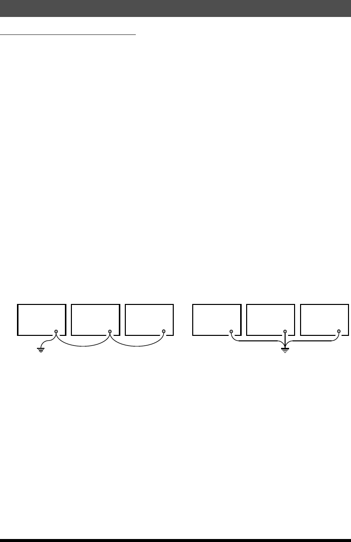
Do not make ground connections from one electrical device to another, and thence to the
ground bus. This so-called “Daisy Chain” grounding technique may nullify any attempt at
effective radio frequency grounding. See the drawings below for examples of proper and
improper ground connections.
Improper Ground Connection
Transceiver
“Daisy Chain”
GNDGND GND
Linear
Amplifier
Power
Supply
Proper Ground Connection
Transceiver
GNDGND GND
Linear
Amplifier
Power
Supply
Application for FCC / IC
FCC ID: K6620651X50 / IC: 511B-20651X50

9
Installation
FT-891 Operating Manual
RF FIELD EXPOSURE
This transceiver is capable of power output in excess of 100 Watts, so customers in the
United States may be required to demonstrate compliance with Federal Communica-
tions Commission (FCC) regulations concerning maximum permissible exposure to radio
frequency energy. Compliance is based on the actual power output used, feedline loss,
antenna type and height, and other factors which can only be evaluated as a system.
Information regarding these regulations may be available from your Dealer, your local
radio club, from the FCC directly (press releases and other information can be found on
the FCC’s site on the World Wide Web at <http://www.fcc.gov>), or from the American
Radio Relay League, Inc. (225 Main St., Newington CT 06111 or <http://www.arrl.org>).
Although there is negligible radio frequency (RF) leakage from the FT-891 transceiver it-
self, its antenna system should be located as far away from humans and animals as prac-
ticable, so as to avoid the possibility of shock due to accidental contact with the antenna
or excessive long-term exposure to RF energy. During mobile operation, do not transmit if
someone is standing adjacent to your antenna, and use the lowest power possible.
Application for FCC / IC
FCC ID: K6620651X50 / IC: 511B-20651X50
10 FT-891 Operating Manual
Front Panel Controls & Switches
①
②
③ ④ ⑥ ⑦ ⑧ ⑩⑤
⑪ ⑫ ⑬ ⑭ ⑮ ⑯
⑨
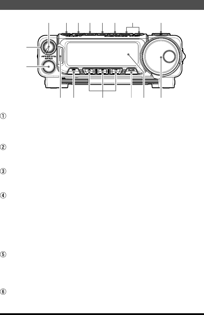
RF/SQL knob
This (outer) SQL/RF knob adjusts the gain of the receiver’s RF and IF stages. Using
Menu Mode “No 05-05 [RF/SQL VR]”, this control may be changed to function as a
Squelch control.
MULTI knob
This detented rotary switch is used for function selection for the [A], [B], [C] keys of
the transceiver.
AF Knob
The (inner) VOL knob adjusts the receiver audio volume level presented to the internal
or external speaker. Clockwise rotation increases the volume level.
MODE key
Pressing either of this key momentarily will change the operating mode. The selections
available are:
à LSB à CWL (CW LSB) à R-L (RTTY LSB) à
à P-L (PACKET LSB) à AM à LSB à
Repeated presses of this key steps through the available selections. Pressing and
holding this key will toggle to the alternate mode. For example, In the LSB or USB
modes, a long press of this key toggles between “LSB” and “USB” mode.
RC/ST key
Press and hold this key for more than one second to write the frequency and data
currently set for VFO-A onto the quick memory bank (QMB)
m 5 channels are available for QMB memories. Press the button briefly to recall the
data written onto the quick memory banks (QMB) one by one.
[VuM] key
Pressing and holding this key for one second (until the double beep) copies the current
operating data into the currently selected memory channel, over-writing any previous
Application for FCC / IC
FCC ID: K6620651X50 / IC: 511B-20651X50

11
Basic Operation
FT-891 Operating Manual
data stored there.
Press this button briefly to display the memory check function screen, where the data
saved in a memory channel may be reviewed.
Press this button again, to close the memory list screen.
[V/M] key
This key toggles frequency control between VFO and the memory system.
m Pressing this key alternately recalls the VFO frequency data and the frequency
data saved in a memory channel by turns.
[A/B] key
Pressing this button momentarily, exchanges the frequency and memory channel data,
of VFO-A and VFO-B.
[DOWN]/[UP] key
Pressing either of these keys momentarily will cause the frequency to be moved up or
down by one frequency band. The selections available are:
..... 1.0 MHz ó 1.8 MHz ó 3.5 MHz ó 5.0 MHz ó 7.0 MHz ó 10 MHz ó 14 MHz
ó 15 MHz ó 18 MHz ó 21 MHz ó 24 MHz ó 28 MHz ó 50 MHz ó 1.0 MHz .....
[Power/Lock] key
Press and hold in the Power key for one second to turn to the transceiver on or off.
Briefly pressing the key while the transceiver is turned ON engages or releases the key
lock.
TX/BUSY Indicator
This indicator glows green when the squelch opens, and turns red during transmit.
[F] key
Press and hold in this key for one second to activate the “Menu” mode.
Multi Function keys
These three keys select many of the most important operating features of the trans-
ceiver.
[CLAR] key
During reception, press this key, then press the MULTI knob then rotate the MULTI
knob to adjust the VFO RX clarifier offset value.
m The clarifier offset value (frequency) can be re-stored to “0 (zero)” by pressing the
[CLAR] key for more than 1 second.
LCD Display
The LCD (Liquid Crystal Display) provides indication of the operating frequency and
other aspects of transceiver status.
MAIN DIAL
This is the main tuning dial for the transceiver. It is used both for frequency tuning as
well as “Menu” setting in the transceiver.
Application for FCC / IC
FCC ID: K6620651X50 / IC: 511B-20651X50
12 FT-891 Operating Manual
Rear Panel Connectors
②① ③ ⑤ ⑥ ⑦④
⑨
⑧
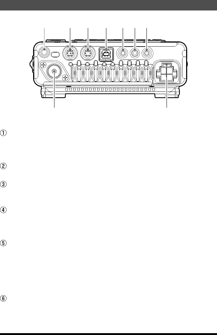
GND
Use this terminal to connect the transceiver to a good earth ground, for safety and
optimum performance. Use a large diameter, short braided cable to make the ground
connections. For details on grounding the transceiver, see “Grounding” on page 7.
TUN/LIN Jack
Connect the optional external antenna tuner “FC-50” or the linear amplifier VL-1000”.
RTTY/DATA Jack
This is the input/output jack to connect a terminal unit for RTTY and TNC for packet
communications.
USB Jack
Connect a computer with a commercially available USB cable to control the transceiver
remotely from the computer using the CAT command. Inputting/Outputting audio sig-
nals and transmission control can also be done from the computer.
ACC Jack
This 3.5-mm 3-pin jack accepts external ALC (Automatic Level Control) voltage from a
linear amplifier on the tip connection, and accepts a “Transmit Request” command on
the ring connection. The main shaft is the ground return.
The “TX Request” connection, when shorted to ground, puts the FT-891 into the trans-
mit mode, and sends out a steady CW carrier, for linear amplifier or manual antenna
tuner adjustment.
KEY Jack
This 3.5-mm, 3-pin jack is used for connection to a CW keyer paddle or a straight key.
Application for FCC / IC
FCC ID: K6620651X50 / IC: 511B-20651X50

13
Rear Panel Connectors
FT-891 Operating Manual
EXT SPKR Jack
This 3.5-mm, 2-pin jack provides variable audio output for an external speaker. The
audio output impedance at this jack is 4 Ω ~ 16 Ω and the level varies according to the
setting of the front panel’s AF control.
ANT Antenna Jack
Connect your HF and/or 50 MHz antenna’s 50 Ω coaxial cable to this M-type (“SO-
239”) connector.
DC IN Jack
This is the DC power supply connection for the transceiver. Use the supplied DC cable
to connect directly to a DC power supply, which must be capable of supplying at least
25 A @13.8 VDC.
Application for FCC / IC
FCC ID: K6620651X50 / IC: 511B-20651X50
14 FT-891 Operating Manual
Basic Operation
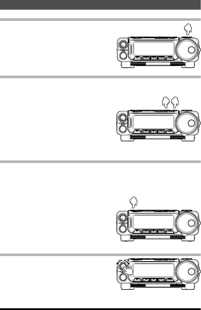
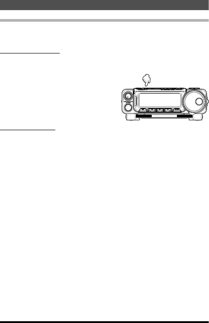
Turning the Transceiver ON and OFF
1. To turn the transceiver ON, press and hold
the PWR/LOCK key for one second.
2. To turn the transceiver OFF, again press and
hold the PWR/LOCK key for one second.
Operating Band Selection
This transceiver covers an incredibly wide frequency range, over which a number of dif-
ferent operating modes are used. Therefore, this transceiver’s frequency coverage has
been divided into different operating bands,
each of with has its own preset frequency steps
and operating modes. You can change the
channel steps and operating mode once you
get started,of course, per the next section.
To change the frequency band, press either the
[DOWN] or [UP] key to move to the next lower
or higher operating band, respectively.
Mode Selection
Pressing either of the [MODE] key momentarily will change the operating mode. The
selections available are:
à LSB à CWL (CW LSB) à R-L (RTTY LSB) à
à P-L (PACKET LSB) à AM à LSB à
Repeated presses of the [MODE] key steps
through the available selections. Pressing
and holding the [MODE] key will toggle to the
alternate mode. For example, In the LSB or
USB modes, a long press of the [MODE] key
toggles between “LSB” and “USB” mode.
Adjusting the Audio Volume Level
Rotate the AF knob to set a comfortable listen-
ing level.
Application for FCC / IC
FCC ID: K6620651X50 / IC: 511B-20651X50
15
Basic Operation
FT-891 Operating Manual
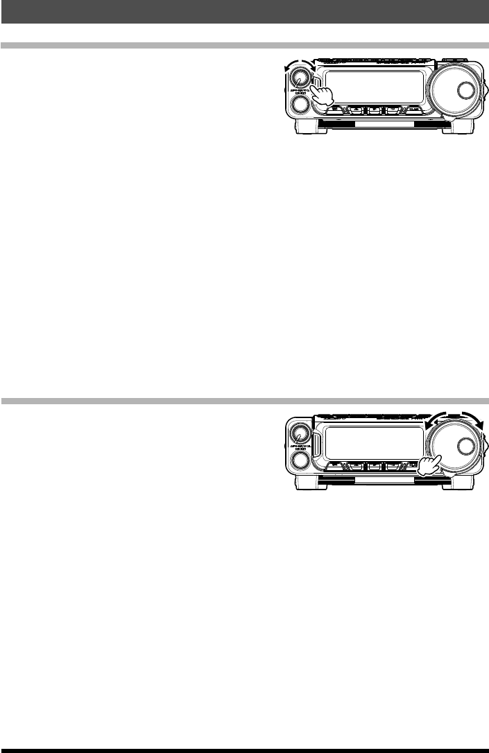
Adjusting the RF Gain and Squelch
The RF/SQL Gain control is configured
differently, depending on the country to which
the FT-891 has been exported. In the U.S.
version, the default function of this control
is “RF Gain.” The configuration of the RF/
SQL Gain control is set via Menu Mode “No
05-05 [RF/SQL VR]”. If your transceiver is configured for “RF Gain” use, rotating this
control fully clockwise in the SSB/CW modes will provide best sensitivity. To reduce the
receiver’s RF Gain somewhat, rotate this control counter-clockwise slightly. You will
observe an increasing number of bars on the S-meter as you rotate the RF Gain control
counter-clockwise; this indicates increasing AGC voltage, which is causing the front-end
gain to be reduced. In the FM mode, with “RF Gain” selected, the FT-891 goes into an
“Auto Squelch” mode, with the Squelch level being preset at the factory. If this control is
configured for “SQL” operation, the FT-891’s RF Gain will be set for maximum sensitivity
in all modes, and the RF/SQL Gain control will function solely as a Squelch control. In
this case, rotate the RF/SQL Gain control to the point where the back-ground noise is just
silenced; this will provide the best sensitivity to weak signals, while keeping the receiver
quiet when no signal is received. The LED just left side the display will glow Green when
the squelch is opened by an incoming signal or noise.
Setting the Operating Frequency
Rotate the DIAL knob to set the frequency.
Clockwise rotation of the DIAL increases the
operating frequency.
Application for FCC / IC
FCC ID: K6620651X50 / IC: 511B-20651X50
16
Basic Operation
FT-891 Operating Manual
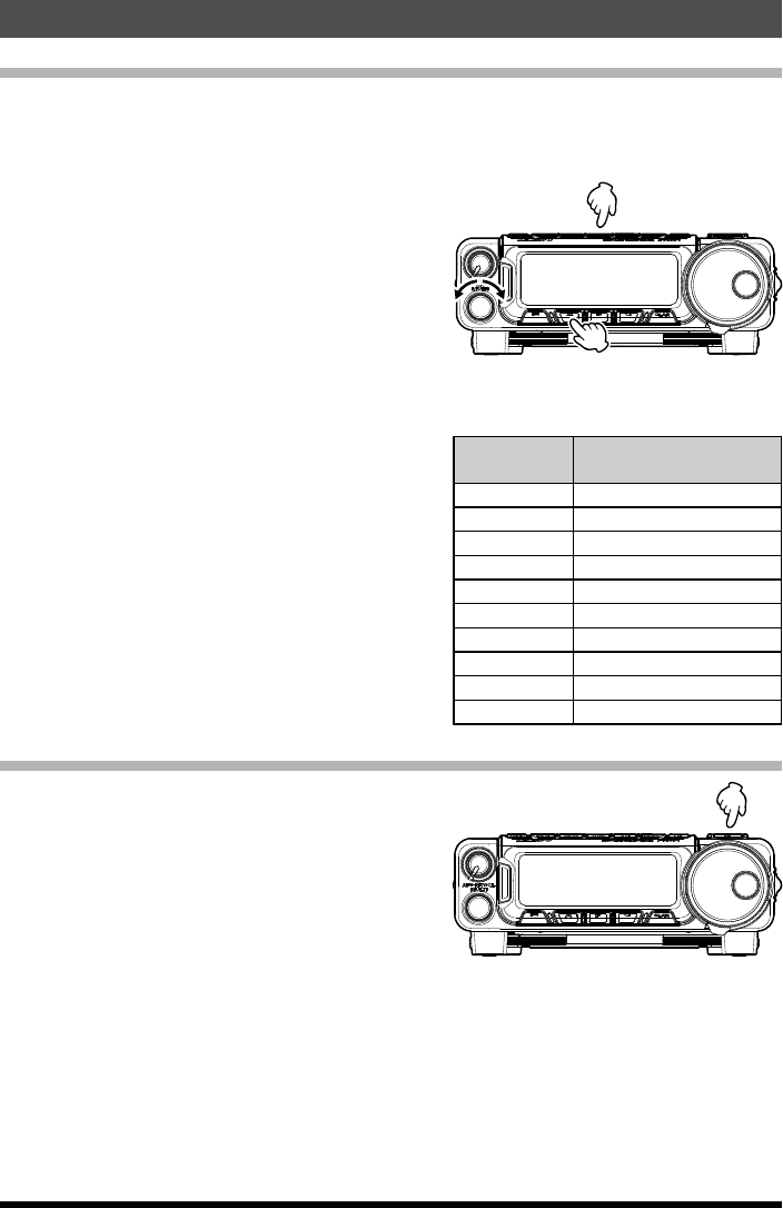
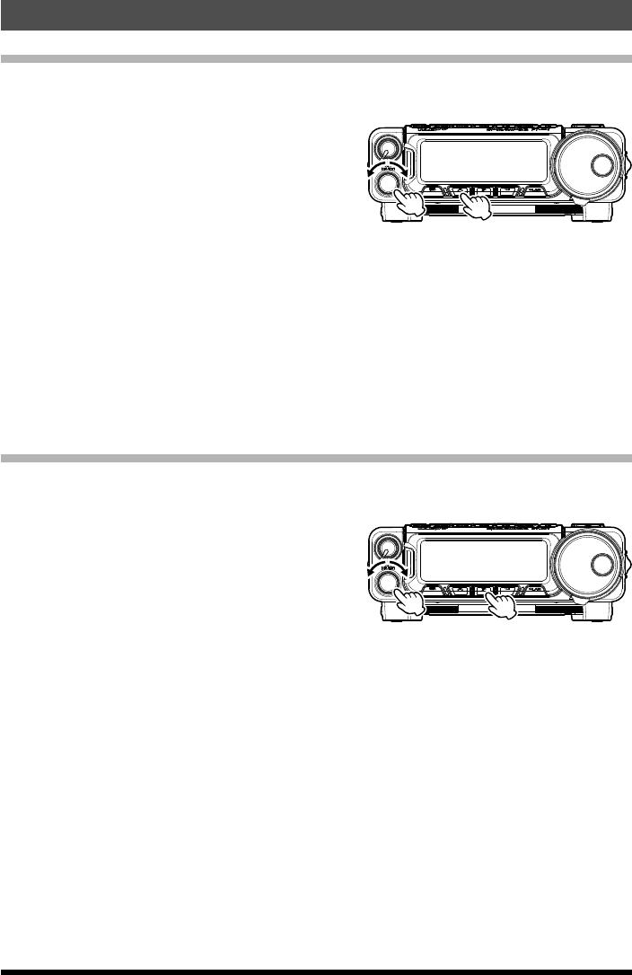
Operation on 60-Meter (5 MHz) Band (U.S. Version Only)
The recently-released 60-meter band is covered, in the FT-891, by fixed memory chan-
nels. These channels are set to USB or CW, and they appear between the “last” PMS
channel (“P-9U”) and the first “regular” memory channel (01ch):
1. Press the [V/M] key once to enter the “Mem-
ory” mode.
2. Rotate the MULTI knob, as needed, un-
til Multi Function Row “F-13 [MCH] [GRP]
[MLIST]” appears on the display.
3. Press the [A](MCH) key, then rotate the
MULTI knob.
4. The memory channel number will appear on the display to signify that rotation of the
MULTI knob will allow selection of the memory channel.
5. Memory channels (“5-01” through “5-10”)
are preprogrammed, at the factory, with the
permitted frequencies in the 5 MHz band,
and the USB or CW mode is automatically
selected on these channels.
6. To exit from 60-meter (5 MHz) operation and
return to the VFO mode, just press the [V/M]
key.
Channel
Number Frequency
5-01 5.332000 MHz (SSB)
5-02 5.348000 MHz (SSB)
5-03 5.358500 MHz (SSB)
5-04 5.373000 MHz (SSB)
5-05 5.405000 MHz (SSB)
5-06 5.332000 MHz (CW)
5-07 5.348000 MHz (CW)
5-08 5.358500 MHz (CW)
5-09 5.373000 MHz (CW)
5-10 5.405000 MHz (CW)
Lock Feature
To activate the key-lock feature, press the
[Power/Lock] key. The “LOCK” icon will appear
on the LCD.
To cancel key-lock, press the [Power/Lock] key
again.
Application for FCC / IC
FCC ID: K6620651X50 / IC: 511B-20651X50

17
Basic Operation
FT-891 Operating Manual
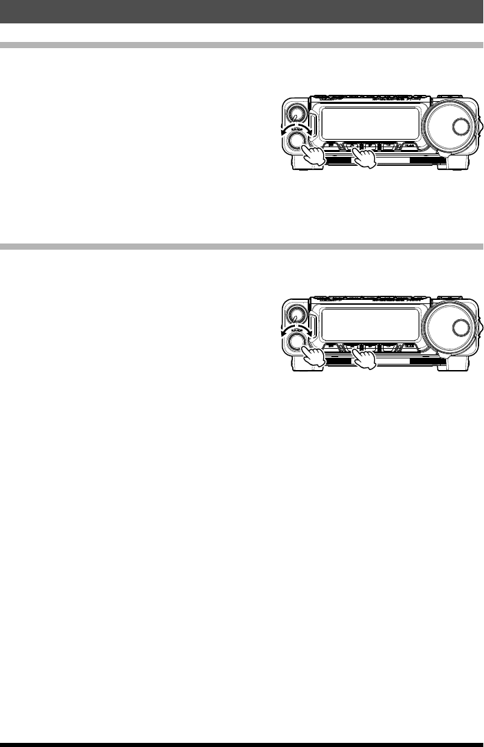
Clarifier (Receiver Incremental Tuning)
The [CLAR] key and MULTI knob are used to offset the receive frequency, the transmit
frequency, or both, from their settings on the VFO-A frequency. Four small numbers on
the Display show the current Clarifier offset. The Clarifier controls on the FT-891 are
designed to allow setting a preset offset (up to ±9.99 kHz) without actually re-tuning, and
then to activate it via the Clarifier [CLAR] key. This feature is ideal for following a drifting
station, or for setting the small frequency offsets sometimes utilized in DX “Split” work.
Here is the technique for utilizing the Clarifier:
1. Press the [CLAR] key. The programmed off-
set will be applied to the receive frequency.
2. Press the MULTI knob, then rotation of the
MULTI knob will allow you to modify your
initial offset on the fly. Offsets of up to ±9.99
kHz may be set using the Clarifier.
3. To cancel Clarifier operation, press the [CLAR] key.
Note: Turning the Clarifier off merely cancels the application of the programmed offset
from the receive and/or the transmit frequencies. To clear the Clarifier offset, and
reset it to “zero,” press and hold the [CLAR] key.
Application for FCC / IC
FCC ID: K6620651X50 / IC: 511B-20651X50
18 FT-891 Operating Manual
Advanced Operation
IF SHIFT
The receiver’s IF SHIFT feature is an effective interference-reduction tool, which allows
you to shift the passband response higher or lower without changing the pitch of the
incoming signal.
1. Rotate the MULTI knob, as needed, until
Multi Function Row “F-05 [SHIFT] [WIDTH]
[NOTCH]” appears on the display.
2. Press the [A](SHIFT) key to activate the IF
SHIFT feature.
3. Rotate the MULTI knob, as needed, to re-
duce or eliminate the interference.
4. To turn the IF SHIFT feature off, press the [F] key. The last setting of the IF SHIFT
control will be retained until you change it again.
AGC (Automatic Gain Control)
The receiver recovery time constant of the AGC system may be modified to match your
operating needs.
1. Rotate the MULTI knob, as needed, un-
til Multi Function Row “F-04 [NB] [AGC]
[MONI]” appears on the display.
2. Press the [B](AGC) key to toggle the AGC
recovery time constant among the following
selections:
AUTO à FAST à MID à SLOW à AUTO à .....
Where “AUTO” represents “FAST” on CW and DIG (AFSK), and “SLOW” on the voice
modes. If you disable the AGC by press and hold the [B](AGC) key, the S-meter (which
monitors AGC voltage) will cease to function. Depending on the setting of the RF Gain
control, incoming signals will probably be distorted if the AGC is turned off.
Application for FCC / IC
FCC ID: K6620651X50 / IC: 511B-20651X50
19
Advanced Operation
FT-891 Operating Manual
Noise Blanker
The IF Noise Blanker may be useful in reducing or eliminating some types of impulse
noise, especially noise generated by automotive ignition systems.
1. Rotate the MULTI knob, as needed, un-
til Multi Function Row “F-04 [NB] [AGC]
[MONI]” appears on the display.
2. Press the [A](NB) key to activate the Noise
Blanker. The “N” icon will appear on the dis-
play, indicating that the Noise Blanker is now
on.
3. To adjust the blanking level, rotate the MULTI knob to set a higher or lower blanking
level (on a scale of 0 to 10).
4. Press the [A](NB) key again to turn the Noise Blanker off.
Note: During very crowded band conditions, you may wish to turn the Noise Blanker
off, as its use will degrade the strong-signal-handling capability of the receiver
somewhat.
IPO (Intercept Point Optimization)
The IPO feature bypasses the receiver RF preamplifier, thereby eliminating the preamp’s
gain.
1. Rotate the MULTI knob, as needed, until
Multi Function Row “F-03 [ATT] [IPO] [NAR]”
appears on the display.
2. Press the [B](IPO) key repeatedly, to set the
desired characteristic of the receiver front
end, ac-cording to the chart below.
AMP1: Amplifie the incoming signals, using a low distortion RF preamplifie.
IPO: Bypasses the RF preamplifie, yielding direct feed to the firs mixer.
3. The selected receiver RF preamplifie will be indicated in the IPO column of the Key
Function Display on the display.
Application for FCC / IC
FCC ID: K6620651X50 / IC: 511B-20651X50
20
Advanced Operation
FT-891 Operating Manual
ATT (Attenuator)
The Attenuator will reduce all signals (and noise) by 10 dB, and it may be used to make
reception more pleasant under extremely noisy conditions.
1. Rotate the MULTI knob, as needed, until
Multi Function Row “F-03 [ATT] [IPO] [NAR]”
appears on the display.
2. Press the [A](ATT) key. The “ATT” indicator
will appear in the display.
3. To restore full signal strength through the Attenuator circuit, press the [A](ATT) key to
return the ATT display to the “OFF” position.
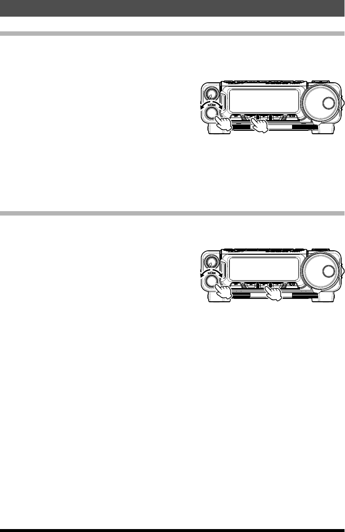
DSP Noise Reduction (DNR)
The Noise Reduction feature of the DSP system may be used to enhance signal-to-noise
ratio on weak signals.
1. Rotate the MULTI knob, as needed, un-
til Multi Function Row “F-06 [DNR] [MOX]
[CONT]”.
2. Press the [A](DNR) key to activate the DSP
Noise Reduction feature.
3. Rotate the MULTI knob to find the point where best signal-to-noise ratio is obtained
under the current noise conditions.
4. Press the [F] key to save the new setting and exit to normal operation.
5. To turn off the DSP Noise Reduction feature, press the [A](DNR) key again.
6. If noise is present at a level which causes indication on the S-meter, the performance
of the Noise Reduction filter may be enhanced by rotating the SQL/RF (RF Gain) con-
trol in a counter-clockwise direction so as to set the (fixed) S-meter reading at the same
level as the noise peaks. This adjustment raises the AGC threshold of the receiver.
Application for FCC / IC
FCC ID: K6620651X50 / IC: 511B-20651X50

21
Advanced Operation
FT-891 Operating Manual
Notch Filter
The DSP system’s Notch Filter may be helpful in removing one or more offending carrier
or heterodyne signals from the audio passband.
1. Rotate the MULTI knob, as needed, until
Multi Function Row “F-05 [SHIFT] [WIDTH]
[NOTCH]”.
2. Press the [C](NOTCH) key to activate the
Notch Filter. The “” icon will appear at the left
side of the “DNF” indication, and the “” nota-
tion will appear at the top on the display. You
will notice that the audio level of the carrier
signal is now being reduced.
3. Rotate the MULTI knob to adjust the “null” position of the Notch filter.
4. Press the [C](DNF) key once more to turn the Notch Filter off.
Application for FCC / IC
FCC ID: K6620651X50 / IC: 511B-20651X50
22 FT-891 Operating Manual
Memory Operation
QMB (Quick Memory Bank) Channels
The “Quick Memory” Bank provides one-touch access to frequencies you want to store
and recall in a hurry. You may store a “QMB” channel into a “regular” memory later, if you
like;use of the “regular” memories will be described later.
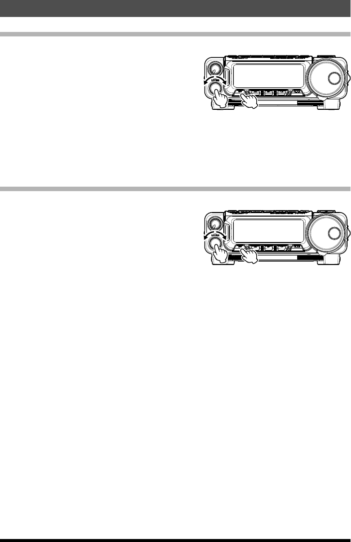
QMB Channel Storage
1. Tune in the desired frequency and set the operating mode and bandwidth. If this is an
FM channel, set up any required CTCSS/DCS and repeater shift configurations.
2. Press and hold in the [RC/ST] key until two
“beeps” are heard. The second beep (heard
one second after the initial beep) provides
audible confirmation that the data has been
stored into the QMB memory.
QMB Channel Recall
1. Press the [RC/ST] key momentarily to recall the QMB memory. “QMB” will appear in
the upper of the display.
2. Press the [V/M] key to return to the previous frequency (either a VFO frequency or a
Memory channel).
Application for FCC / IC
FCC ID: K6620651X50 / IC: 511B-20651X50
23
Memory Operation
FT-891 Operating Manual
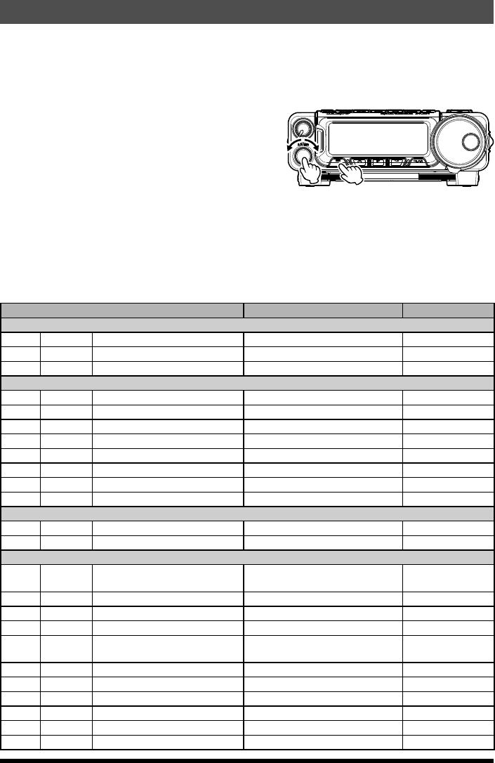
Memory Operation on “Regular” Memory Channels
Most Memory operation will be conducted in the “regular” memory registers. There are 99
memory channels available for storage and recall of important frequencies.
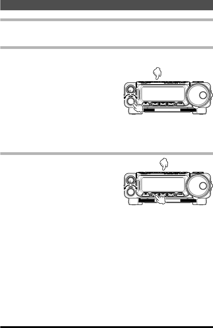
Normal Memory Storage
1. In the VFO mode, select the desired frequency, repeater shift, CTCSS/DCS tone, and
TX power level.
2. Press the [VuM] key momentarily to enter
the “Memory Check” mode, which is used to
find an unused memory channel. Rotate the
MULTI knob to select the channel number
on which you wish to store the current fre-
quency data.
3. If you just want to program in the frequency data, press and hold in the [VuM] key for
one second until you hear two beeps, a second apart; the second beep confirms that
the frequency information was successfully stored.
Memory Channel Recall
1. Press the [V/M] key once to enter the “Mem-
ory” mode.
2. Rotate the MULTI knob, as needed, un-
til Multi Function Row “F-13 [MCH] [GRP]
[MLIST]” appears on the display.
3. Press the [A](MCH) key, then rotate the
MULTI knob.
4. Press the [A](MCH) key and then rotate the MULTI knob to select the desired memory
channel.
Application for FCC / IC
FCC ID: K6620651X50 / IC: 511B-20651X50
24 FT-891 Operating Manual
Miscellaneous Settings
Display Contrast
The LCD’s contrast may be adjusted using the Menu Mode, as well.
1. Press and hold in the [F] key for one second
to activate the Menu mode.
2. Rotate the MULTI knob to select Menu Mode
Menu Mode “No 02-03 [LCD CONTRAST]”.
3. Press the MULTI knob, and then rotate the
MULTI knob to adjust the contrast. As you
make the adjustment, you will be able to see
the effects of your changes.
4. When you have completed the adjustment, press the [F] key exit the Menu mode.
Display Dimmer
The LCD illumination level may also be adjusted using the Menu Mode.
1. Press and hold in the [F] key for one second
to activate the Menu mode.
2. Rotate the MULTI knob to select Menu Mode
Menu Mode “No 02-05 [DIMMER LCD]”.
3. Press the MULTI knob, and then rotate the
MULTI knob to adjust the display illumination
for a comfortable brightness level. As you
make the adjustment, you will be able to see
the effects of your changes.
4. When you have completed the adjustment, press the [F] key exit the Menu mode.
Application for FCC / IC
FCC ID: K6620651X50 / IC: 511B-20651X50

25FT-891 Operating Manual
Reset Procedure
In some instances of erratic or unpredictable operation, the cause may be corruption of
data in the microprocessor (due to static electricity, etc.). If this happens, resetting the
microprocessor may restore normal operation. Note that all memories will be erased if
you do a complete microprocessor reset, as described below.
Microprocessor Resetting
To clear all memories and other settings to factory defaults:
1. Turn the radio OFF.
2. Press and hold the [F] and [CLAR] keys
while turning the radio ON. Once the trans-
ceiver comes on, release the buttons.
Application for FCC / IC
FCC ID: K6620651X50 / IC: 511B-20651X50
26 FT-891 Operating Manual
Setup (Menu) Mode
The FT-891 Setup (Menu) mode, already described in parts of many previous chapters,
is easy to activate and setup. The Menus may be used to configure many of transceiver
parameters, some of which have not been detailed previously. Use the following
procedure to activate the Setup (Menu) mode:
1. Press and hold in the [F] key for one second
to activate the Menu mode.
2. Rotate the MULTI knob to select the Menu
Item to be adjusted.
3. Press the MULTI knob momentarily to en-
able adjustment of the selected Menu item,
and then rotate the MULTI knob to perform
the actual adjustment.
4. After completing the selection and adjust-
ment, press the [F] key to exit the Setup
menu and resume normal operation.
Menu / Item Available Values Default
AGC
01-01 AGC FAST DELAY 20 - 4000 msec 300
01-02 AGC MID DELAY 20 - 4000 msec 700
01-03 AGC SLOW DELAY 20 - 4000 msec 3000
DISPLAY
02-01 MY CALL --- FT-891
02-02 MY CALL INDI 0 - 5 1sec
02-03 LCD CONTRAST 1 - 15 8
02-04 DIMMER BACKLIT 1 - 4 8
02-05 DIMMER LCD 1 - 15 8
02-06 DIMMER TX/BUSY 1 - 4 8
02-07 PEAK HOLD OFF/0.5/1.0/2.0 sec OFF
02-08 ZIN LED ENABLE/DISABLE ENABLE
DVS
03-01 DVS RX OUT LEVEL 0 - 100 50
03-02 DVS TX OUT LEVEL 0 - 100 50
KEYER
04-01 KEYER TYPE OFF/BUG/ELEKEY-A/
ELEKEY-B/ELEKEY-Y/ACS
ELEKEY-B
04-02 KEYER DOT/DASH NOR/REV NOR
04-03 CW WEIGHT 2.5 - 4.5 3.0
04-04 BEACON INTERVAL OFF/1 - 690 sec OFF
04-05 NUMBER STYLE 1290/AUNO/AUNT/A2NO/
A2NT/12NO/12NT
1290
04-06 CONTEST NUMBER 0 - 9999 1
04-07 CW MEMORY 1 TEXT/MESSAGE TEXT
04-08 CW MEMORY 2 TEXT/MESSAGE TEXT
04-09 CW MEMORY 3 TEXT/MESSAGE TEXT
04-10 CW MEMORY 4 TEXT/MESSAGE TEXT
04-11 CW MEMORY 5 TEXT/MESSAGE TEXT
Application for FCC / IC
FCC ID: K6620651X50 / IC: 511B-20651X50

27
Setup (Menu) Mode
FT-891 Operating Manual
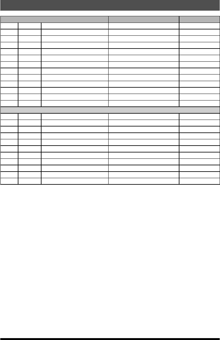
Menu / Item Available Values Default
GENERAL
05-01 NB WIDTH 1/3/10msec 1(3msec)
05-02 NB REJECTION 10/30/50dB 1(30dB)
05-03 NB LEVEL 0 - 10 5
05-04 BEEP LEVEL 0 - 100 50
05-05 RF/SQL VR RF/SQL RF
05-06 CAT RATE 4800/9600/19200/38400 bps 4800
05-07 CAT TOT 10/100/1000/3000 msec 10
05-08 CAT RTS ENABLE/DISABLE ENABLE
05-09 MEM GROUP ENABLE/DISABLE DISABLE
05-10 QUICK SPLIT FRE -20 - 0 - 20 kHz +5
05-11 TX TOT OFF/1 - 30 min OFF
05-12 MIC SCAN ENABLE/DISABLE ENABLE
05-13 MIC SCAN RESUME CAR/5Sec TIME
05-14 REF FREQ ADJ -25 - 0 - 25 0
05-15 CLAR MODE SELECT RX/TX/TRX RX
05-16 APO OFF/1h/2h/4h/6h/8h/10h/12h OFF
05-17 FAN CONTROL NORMAL/CONTEST NORMAL
MODE AM
06-01 AM LCUT FREQ OFF /100 - 1000 OFF
06-02 AM LCUT SLOPE -6 / -18 6
06-03 AM HCUT FREQ 700 - 4000 / OFF OFF
06-04 AM HCUT SLOPE -6 / -18 6
06-05 AM MIC SELECT MIC/REAR MIC
06-06 AM OUT LEVEL 0 - 100 50
06-07 AM PTT SELECT DAKY/RTS/DTR DAKY
06-08 AM DATA GAIN 0 - 100 50
MODE CW
07-01 CW LCUT FREQ OFF /100 - 1000 250
07-02 CW LCUT SLOPE -6 / -18 18
07-03 CW HCUT FREQ 700 - 4000 / OFF 1200
07-04 CW HCUT SLOPE -6 / -18 18
07-05 CW OUT LEVEL 0 - 100 50
07-06 CW AUTO MODE OFF/50M/On OFF
07-07 CW BFO USB/LSB/AUTO USB
07-08 CW BK-IN TYPE SEMI/FULL SEMI
07-09 CW BK-IN DELAY 30 - 3000msec 200msec
07-10 CW WAVE SHAPE 1/2/4/6 msec 4
07-11 CW FREQ DISPLAY DIRECT F/P OFFSET PITCH OFFSET
07-12 PC KEYING OFF/DAKY/RTS/DTR OFF
07-13 QSK DELAY TIME 15/20/25/30 msec 15
MODE DAT
08-01 DATA MODE PSK/OTHERS PSK
08-02 PSK TONE 1000/1500/2000Hz 1000
08-03 OTHER DISP -3000 - 0 - 3000 Hz 0
08-04 OTHER SHIFT -3000 - 0 - 3000 Hz 0
08-05 DATA LCUT FREQ OFF /100 - 1000 300
08-06 DATA LCUT SLOPE -6 / -18 18
Application for FCC / IC
FCC ID: K6620651X50 / IC: 511B-20651X50

28
Setup (Menu) Mode
FT-891 Operating Manual
Menu / Item Available Values Default
08-07 DATA HCUT FREQ 700 - 4000 / OFF 3000
08-08 DATA HCUT SLOPE -6 / -18 18
08-09 DATA IN SELECT MIC/REAR REAR
08-10 DATA PTT SELECT DAKY/RTS/DTR DAKY
08-11 DATA OUT LEVEL 0 - 100 50
MODE FM
09-01 FM MIC SEL MIC/REAR MIC
09-02 FM OUT LEVEL 0 - 100 50
09-03 PKT PTT SELECT DAKY/RTS/DTR DAKY
09-04 FM PKT TX GAIN 0 - 100 50
09-05 RPT SHIFT 28MHz 0 - 1.0MHz 100
09-06 RPT SHIFT 50MHz 0 - 4.0MHz 1000
09-07 DCS POLARITY Tn-Rn/Tn-Riv/Tiv-Rn/Tiv-Riv Tn-Rn
MODE RTY
10-01 RTTY LCUT FREQ OFF /100 - 1000 300
10-02 RTTY LCUT SLOPE -6 / -18 18
10-03 RTTY HCUT FREQ 700 - 4000 / OFF 3000
10-04 RTTY HCUT SLOPE -6 / -18 18
10-05 RTTY SHIFT PORT SHIFT/DTR/RTS SHIFT
10-06 RTTY POLARITY-R NOR/REV NOR
10-07 RTTY POLARITY-T NOR/REV NOR
10-08 RTTY OUT LEVEL 0 - 100 50
10-09 RTTY SHIFT FREQ 170/200/425/850 Hz 170
10-10 RTTY MARK FREQ 1275/2125 Hz 2125
MODE SSB
11-01 SSB LCUT FREQ OFF /100 - 1000 100
11-02 SSB LCUT SLOPE -6 / -18 6
11-03 SSB HCUT FREQ 700 - 4000 / OFF 3000
11-04 SSB HCUT SLOPE -6 / -18 6
11-05 SSB MIC SELECT MIC/REAR MIC
11-06 SSB OUT LEVEL 0 - 100 50
11-07 SSB PTT SELECT DAKY/RTS/DTR DAKY
11-08 SSB-TX-BPF 1-30/1-29/2-28/3-27/4-26 300-2700
RX DSP
12-01 APF-WIDTH APF-N/APF-M/APF-W MEDIUM
12-02 CONTOUR LEVEL -40 - 0 - 20 -15
12-03 CONTOUR WIDTH 1 - 11 10
12-04 IF-NOTCH-WIDTH NARROW/WIDE WIDE
SCOPE
13-01 SCP START CYCLE OFF/3/5/10sec OFF
13-02 ASC DIAL SPEED 1/2/3/4/5/DISABLE 4
13-03 SCP SPAN FREQ. 37.5k/75k/150k/375k/750kHz 150kHz
TX AUDIO
14-01 EQ1 FREQ OFF/100 - 700 OFF
14-02 EQ1 LEVEL -20 - 0 - 10 +5
14-03 EQ1 BWTH 1 - 10 10
14-04 EQ2 FREQ OFF/700 - 1500 OFF
14-05 EQ2 LEVEL -20 - 0 - 10 +5
Application for FCC / IC
FCC ID: K6620651X50 / IC: 511B-20651X50
29
Setup (Menu) Mode
FT-891 Operating Manual
Menu / Item Available Values Default
14-06 EQ2 BWTH 1 - 10 10
14-07 EQ3 FREQ OFF/1500 - 2000/3200 OFF
14-08 EQ3 LEVEL -20 - 0 - 10 +5
14-09 EQ3 BWTH 1 - 10 10
14-10 P-EQ1 FREQ OFF/100 - 700 200
14-11 P-EQ1 LEVEL -20 - 0 - 10 0
14-12 P-EQ1 BWTH 1 - 10 2
14-13 P-EQ2 FREQ OFF/700 - 1500 800
14-14 P-EQ2 LEVEL -20 - 0 - 10 0
14-15 P-EQ2 BWTH 1 - 10 1
14-16 P-EQ3 FREQ OFF/1500 - 2000/3200 2100
14-17 P-EQ3 LEVEL -20 - 0 - 10 0
14-18 P-EQ3 BWTH 1 - 10 1
TX GNRL
15-01 HF TX MAX POWER 5 - 100W 100
15-02 50M TX MAX POWER 5 - 100W 100
15-03 TUNER SELECT OFF/EXT1/EXT2/ATAS/L.AMP OFF
15-04 VOX SELECT MIC/DVOX MIC
15-05 VOX GAIN 0 - 100 50
15-06 VOX DELAY 30 - 300 - 3000 msec 500msec
15-07 ANTI VOX GAIN 0 - 100 50
15-08 DATA VOX GAIN 0 - 100 50
15-09 DATA VOX DELAY 30 - 300 - 3000 msec 100msec
15-10 ANTI DVOX GAIN 0 - 100 0
15-11 EMERGENCY FREQ ENABLE/DISALE DISABLE
Application for FCC / IC
FCC ID: K6620651X50 / IC: 511B-20651X50

30 FT-891 Operating Manual
Specifications
General
Frequency Range: Tx 1.8 - 54 MHz (Amateur bands only)
Rx 0.03 - 55.999995 MHz
Channel Step: 2/5//10 Hz (SSB, CW)
10/100 Hz (AM, FM)
Frequency Stability: ±0.5 ppm [-4 °F to +140 °F (-20 °C to +50 °C)]
Modes of Emission: A1A (CW), A3E (AM), J3E (LSB, USB), F3E (FM)
Antenna Impedance: 50 Ohms, unbalanced
Supply voltage: 13.8 V DC ±15%, negative ground
Current Consumption (typical): Rx: 2.0 A (signal present)
Tx: 23 A
Operating Temperature Range: -14° F to +122° F (-10° C to +50° C)
Case Size (WxHxD): 6.1” x 2.0” x 8.6” (155 x 52 x 218 mm) (w/o knobs)
Weight (Approx.): 4.18 lb (1.9 kg)
Transmitter
Output Power: 100 W
Modulation Type: J3E (SSB): Balanced,
A3E (AM): Low-Level,
F3E (FM): Variable Reactance
Maximum Deviation: ±5 kHz (Wide)
±2.5 kHz (Narrow)
Spurious Radiation: Better than -50 dB (1.8 MHz - 30 MHz Amateur bands)
Better than -63 dB (50 MHz Amateur bands)
Microphone Impedance: 600 Ohms (200 to 10 kOhms)
Receiver
Circuit Type: SSB/CW/AM: Triple-conversion Superheterodyne
FM: Double Conversion Superheterodyne
Ifs: SSB/CW/AM: 69.450 MHz/450 kHz/24 kHz
FM: 69.450 MHz/450 kHz
Sensitivity: SSB/CW (S/N 10 dB)
0.158μV(1.8-30MHz)
0.125μV(50-54MHz)
AM (S/N 10 dB)
5μV(0.5-1.8MHz)
1.6μV(1.8-30MHz)
1.25μV(50-54MHz)
FM (SINAD 12 dB)
0.35μV(29MHz,50-54MHz)
Application for FCC / IC
FCC ID: K6620651X50 / IC: 511B-20651X50

31
Specifications
FT-891 Operating Manual
Selectivity Mode –6dB –60dB
SSB/CW 2.4 kHz or better 3.6 kHz or less
CW-N 500 Hz or better 750 Hz or less
AM 6 kHz or better 15 kHz or less
FM 12 kHz or better 30 kHz or less
FM-N 9 kHz or better 25 kHz or less
Maximum AF Output: 2.5 W into 4 ohms with 10% THD
Audio Output Impedance: 4 to 16 Ohms (8 Ohms: nominal)
Conducted Radiation: Less than 4 nW
Specifications are subject to change, in the interest of technical improvement, without
notice or obligation, and are guaranteed only within the amateur bands.
Application for FCC / IC
FCC ID: K6620651X50 / IC: 511B-20651X50

32 FT-891 Operating Manual
Note
Application for FCC / IC
FCC ID: K6620651X50 / IC: 511B-20651X50

33
Note
FT-891 Operating Manual
Application for FCC / IC
FCC ID: K6620651X50 / IC: 511B-20651X50

34 FT-891 Operating Manual
This equipment has been tested and found to comply with the limits for a Class B digital device,
pursuant to Part 15 of the FCC Rules. These limits are designed to provide reasonable protection
against harmful interference in a residential installation. This equipment generates, uses and can
radiate radio frequency energy and, if not installed and used in accordance with the instructions,
may cause harmful interference to radio communications. However, there is no guarantee that
interference will not occur in a particular installation.
If this equipment does cause harmful interference to radio or television reception, which can
be determined by turning the equipment off and on, the user is encouraged to try to correct the
interference by one or more of the following measures:
Increase the separation between the equipment and receiver.
Connect the equipment into an outlet on a circuit different from that to which the receiver is
connected.
Consult the dealer or an experienced radio/TV technician for help.
1. Changes or modifications to this device that are not expressly approved by YAESU MUSEN could
void the user’s authorization to operate this device.
2. This device complies with part 15 of the FCC Rules. Operation is subject to the following two
conditions: (1) This device may not cause harmful interference, and (2) this device must accept any
interference including received, interference that may cause undesired operation.
3. The scanning receiver in this equipment is incapable of tuning, or readily being altered, by the User
to operate within the frequency bands allocated to the Domestic public Cellular Telecommunications
Service in Part 22.
This device complies with Industry Canada license-exempt RSS standard(s). Operation is subject
to the following two conditions: (1) this device may not cause interference, and (2) this device must
accept any interference, including interference that may cause undesired operation of the device.
Le présent appareil est conforme aux CNR d’Industrie Canada applicables aux appareils radio
exempts de licence. L’exploitation est autorisée aux deux conditions suivantes : (1) l’appareil ne doit
pas produire de brouillage, et (2) l’utilisateur de l’appareil doit accepter tout brouillage radioélectrique
subi, même si le brouillage est susceptible d’en compromettre le fonctionnement.
DECLARATION BY MANUFACTURER
The Scanner receiver is not a digital scanner and is incapable of being converted or modified to a
digital scanner receiver by any user.
WARNING: MODIFICATION OF THIS DEVICE TO RECEIVE CELLULAR RADIOTELEPHONE
SERVICE SIGNALS IS PROHIBITED UNDER FCC RULES AND FEDERAL LAW.
CAN ICES-3 (B) / NMB-3 (B)
Application for FCC / IC
FCC ID: K6620651X50 / IC: 511B-20651X50
Application for FCC / IC
FCC ID: K6620651X50 / IC: 511B-20651X50

Copyright 2016
YAESU MUSEN CO., LTD.
All rights reserved.
No portion of this manual
may be reproduced
without the permission of
YAESU MUSEN CO., LTD.
Printed in Japan
YAESU MUSEN CO., LTD.
Tennozu Parkside Building
2-5-8 Higashi-Shinagawa, Shinagawa-ku, Tokyo 140-0002 Japan
YAESU USA
6125 Phyllis Drive, Cypress, CA 90630, U.S.A.
YAESU UK
Unit 12, Sun Valley Business Park, Winnall Close
Winchester, Hampshire, SO23 0LB, U.K.
*EH065H100*
EH065H100
Application for FCC / IC
FCC ID: K6620651X50 / IC: 511B-20651X50