Yaesu Musen 20665X20 DUAL BAND ANALOGUE SCANNING RECEIVER - AMATEUR RADIO User Manual Operating Manual
Yaesu Musen Co., Ltd. DUAL BAND ANALOGUE SCANNING RECEIVER - AMATEUR RADIO Operating Manual
UserManual.wiki
>
Yaesu Musen
>
20665X20 User Manual
User Manual
Navigation menu
Upload a User Manual
Namespaces
Wiki Guide
HTML
PDF
Info
Views
User Manual
Discussion / Help
Navigation
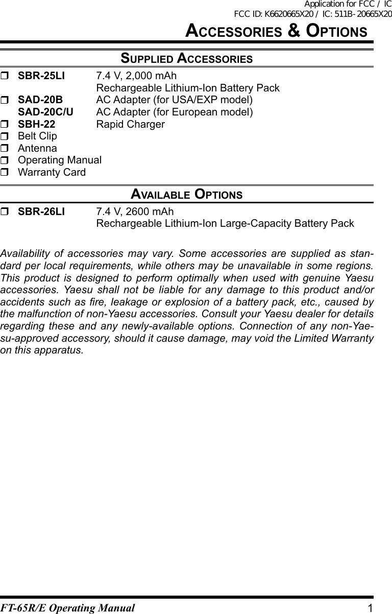
![COntrOl & COnneCtiOns (side panel) PTT (Push To Talk) Switch • Press this switch to transmit, and release it (to receive) after your transmis-sion is completed. • In the Set mode, press this switch to save the new setting and return to normal operation. MONI/T.CALL Switch(selectable version from Set mode) USA/EXP Version: Pressing this switch opens the noise squelching action, allowing you to hear very weak signals near the background noise level temporarily. Europe Version: Pressing this switch activates the T-CALL (1750 Hz) for repeater access. F/W key • Press this key, then press [0 SET] to activate Set mode. • Press this key, then press the [6] key to lock out the keypad. SP Jack This three-conduc-tor miniature jack provides connection pointsforexternalspeaker. MIC Jack This three-conduc-tor miniature jack provides connection points for microphone audio, earphone au-dio, PTT, and ground.3FT-65R/E Operating ManualApplication for FCC / IC FCC ID: K6620665X20 / IC: 511B-20665X20](https://usermanual.wiki/Yaesu-Musen/20665X20/User-Guide-3189820-Page-5.png)
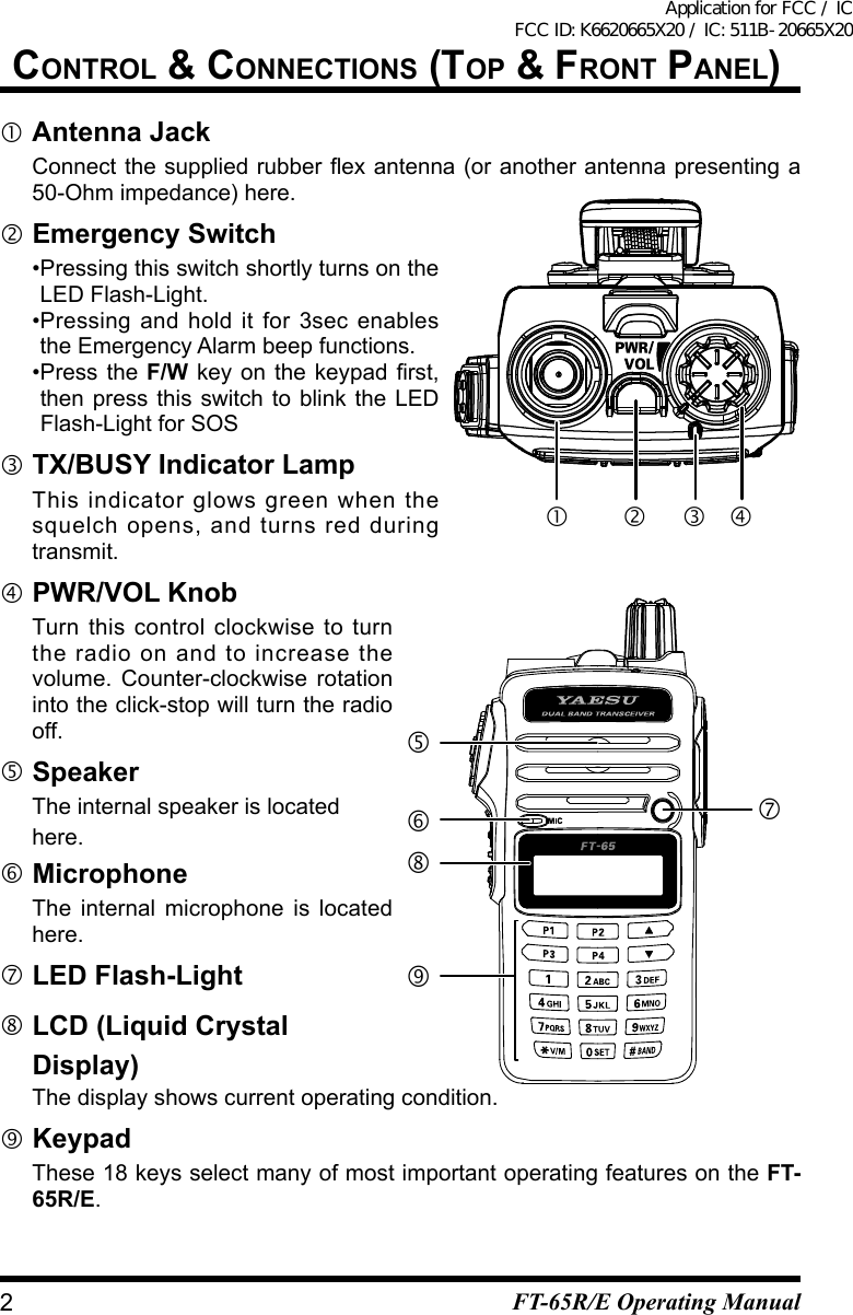
![OperatiOnswitChing pOwer On and OFF Be sure the Battery Pack is installed, and that the battery is fully charged. Connect the antenna to the top panel Antenna jack. Rotate the top panel’s PWR/VOL knob out of the click-stop to turn on the radio. The current DC supply voltage will be indicated on the display for 2 seconds. After this 2 second interval, the dis-play will resume its normal indication of the oper-ating frequency. To turn the radio off, turn the PWR/VOL knob fully counter-clockwise into the click stop position.adjusting the audiO vOluMe level and squelCh setting You may rotate The PWR/VOL knob to adjust the receiver level for a comfortable listing level, using the background noise as a reference. To set the squelch level, press F/W key and then press MONI/T.CALL Switch to open the SQ LEVEL mode. Press the [] or [] key to select the level which the background noise is muted. Press PTT switch to save the squelch setting and back to the normal operation.seleCting the Operating band Press the [#BAND] key repetitively. This key tog-gles frequency control between 144 MHz Band and 430 MHz Band each time you press the [#BAND] key. Once you have selected the desired band, you may initiate manual tuning (or scanning) per the discussioninthenextchapter.Frequency RangeRX TX RX TXUSA model 136-174 MHz 144-148 MHz 400-480 MHz 430-450 MHzEU model 136-174 MHz 144-146 MHz 400-480 MHz 430-440 MHzEXP model 136-174 MHz 136-174 MHz 400-480 MHz 400-470 MHz6FT-65R/E Operating ManualApplication for FCC / IC FCC ID: K6620665X20 / IC: 511B-20665X20](https://usermanual.wiki/Yaesu-Musen/20665X20/User-Guide-3189820-Page-8.png)
![FrequenCy navigatiOnThe FT-65R/E will initially be operating in the “VFO” mode, a channelized sys-tem which allows free tuning throughout the currently-selected operating band.Three basic frequency navigation methods are available on the FT-65R/E:1) Tuning FrequencyPressing the [] or [] key allows tuning in the pre-programmed steps estab-lished for the current operating band. [] key causes the FT-65R/E to be tuned toward a higher frequency, while [] key will lower the operating frequency.2) Direct Keypad Frequency EntryThe desired operating frequency may be entered directly from the keypad.To enter a frequency from the keypad, just press the numbered digits on the keypad in the proper sequence. Examples: To enter 145.560 MHz, press [1] [4] [5] [5] [6] [0]3) ScanningPress and hold in either the [] or [] key for one second to initiate upward or downward scanning, re-spectively (Manual VFO Scan).For scanning within a limited sub-band range, from the VFO mode, press and hold in the [#BAND] key for one second and to begin scanning toward a high-erfrequencywithinthepreviously-denedsub-band(ProgrammedVFOScan).If you wish to reverse the direction of the scan (i.e. toward a lower frequency, instead of a higher frequency), just push the [] key while the FT-65R/E is scanning. The scanning direction will be reversed. To revert to scanning toward a higher frequency once more, push the [].The scanner will stop when it receives a signal strong enough to break through the Squelch threshold. The FT-65R/E will then hold on that frequency accord-ing to the setting of the “RESUME” mode (Set Mode Item 25: RESUME). Press the PTT switch momentarily to cancel the scanning. This only stops the scan; it does not cause transmission to occur.7OperatiOnFT-65R/E Operating ManualApplication for FCC / IC FCC ID: K6620665X20 / IC: 511B-20665X20](https://usermanual.wiki/Yaesu-Musen/20665X20/User-Guide-3189820-Page-9.png)
![transMissiOnOnce you have set up an appropriate frequency inside one of the 144 MHz or 430 MHz Amateur bands on which the FT-65R/E can transmit, you’re ready to go on the air! These are the most basic steps; more advanced aspects of transmitter operation will be discussed later. To transmit, press the PTT switch, and speak into the front panel micro-phone (located in the lower left-hand corner of the speaker grille) in a nor-mal voice level. The TX/BUSY indicator will glow red during transmission. To return to the receive mode, release the PTT switch. During transmission, the relative power level will be indicated on the bar graphatthebottomoftheLCD;fullscaledeectionconrms“High Power” operation,whiledeectionofonebarindicates“Low Power” operation. Five bars indicates “Medium Power” operation. Additionally, the “LOW” icon will appear at the bottom of the display while operating on the “Low Power” and “Medium Power” settings.Changing the Transmitter Power LevelTo change the power level: Press the F/W key, then press the [3] key. The LCD shows the current pow-er output level. Press the [] or [] key to select the desired power output level. Available selections are “HI ” (5 W), “MID” (2.5 W), and “LOW” (0.5 W). When you have made your choice, press the PTT switch to save the new setting and return to normal operation.8OperatiOnFT-65R/E Operating ManualApplication for FCC / IC FCC ID: K6620665X20 / IC: 511B-20665X20](https://usermanual.wiki/Yaesu-Musen/20665X20/User-Guide-3189820-Page-10.png)
![advanCed OperatiOnNow that you’re mastered the basics of FT-65R/E operation, let’s learn more about some of the really neat features.keypad lOCkingIn order to prevent accidental frequency change or inadvertent transmission, various aspects of the FT-65R/E’s keypad may be locked out. The possible lock-out combinations are:Display OperationKEY Just the front panel keypad is locked outPTT The PTT switch is locked out (TX not possible)P+K Both the PTT switch and keypad are locked outTo lock out the keys:1. Press the F/W key, then press the [0 SET] key to enter the Set mode.2. Press the [] or [] key to select Set Mode Item 15: KEY LOCK.3. Press the F/W key momentarily to enable adjustment of this Item.4. Press the [] or [] key to choose between one of the locking schemes as outlined above.5. When you have made your selection, press the PTT switch to save the new setting and return to normal operation.To activate the locking feature, (1) press and hold in the [6] key for one second, or (2) press the F/W key, then press the [6] key. The “ ” icon will appear on the LCD. To cancel locking, repeat this process.9FT-65R/E Operating ManualApplication for FCC / IC FCC ID: K6620665X20 / IC: 511B-20665X20](https://usermanual.wiki/Yaesu-Musen/20665X20/User-Guide-3189820-Page-11.png)
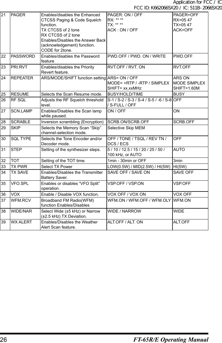
![repeater OperatiOnRepeater stations, usually located on mountaintops or other high locations, pro-vide a dramatic extension of the communication range for low-powered hand-held or mobile transceivers. The FT-65R/E includes a number of features which make repeater operation simple and enjoyable.repeater shiFtsYour FT-65R/Ehasbeencongured,atthefactory,fortherepeatershiftscus-tomary in your country. For the 144 MHz band shift will be 600 kHz; on the 430 MHz band, the shift may be 1.6 MHz, 7.6 MHz, or 5 MHz (USA version).Depending on the part of the band in which you are operating, the repeater shift may be either downward () or upward ( ), and one of these icons will ap-pear at the top of the LCD when repeater shifts have been enabled.autOMatiC repeater shiFt (ars)The FT-65R/E provides a convenient Automatic Repeater Shift feature, which causes the appropriate repeater shift to be applied automatically whenever you tune into the designated repeater sub-bands in your country. These sub-bands are shown below.If the ARS feature does not appear to be working, you may have accidentally disabled it.To re-enable ARS: 1. Press the F/W key, then press the [0 SET] key to enter the Set mode.2. Press the [] or [] key to select Set Mode Item 24: REPEATER.3. Press the F/W key to enable adjustment of this Item.4. Press the [] or [] key to select “ARS”, then press the F/W key.5. Press the [] or [] key to select “ARS. ON”, then press the F/W key.6. When you have made your selection, press the PTT switch to save the new setting and return to normal operation.Manual repeater shiFt aCtivatiOnIf the ARS feature has been disabled, or if you need to set a repeater shift di-rection other than that established by the ARS, you may set the direction of the repeater shift manually.To do this:1. Press the F/W key, then press the [4] key to enable selection of the repeater shift direction.The [4] key is a “short-cut” to Set Mode Item 24: REPEATER.2. Press the F/W key to enable adjustment of this Item.10 FT-65R/E Operating ManualApplication for FCC / IC FCC ID: K6620665X20 / IC: 511B-20665X20](https://usermanual.wiki/Yaesu-Musen/20665X20/User-Guide-3189820-Page-12.png)
![3. Press the [] or [] key to select “ARS”, then press the F/W key.4. Press the [] or [] key to select “ARS. ON”, then press the F/W key.5. Press the [] or [] key to select “MODE“, then press the F/W key.6. Press the [] or [] key to select “–REP,” “+REP” and “SIMPLEX”, then press F/W key.7. Press the [] or [] key to select “SHIFT”, then press the F/W key.8. Press the [] or [] key to set the SHIFT frequency, then press the F/W key.7. When you have made your selection, press the F/W key, then press the PTT switch to save the new setting and return to normal operation.11repeater OperatiOnFT-65R/E Operating ManualApplication for FCC / IC FCC ID: K6620665X20 / IC: 511B-20665X20](https://usermanual.wiki/Yaesu-Musen/20665X20/User-Guide-3189820-Page-13.png)
![CtCss/dCs OperatiOnCtCss OperatiOnMany repeater systems require that a very-low-frequency audio tone be super-imposed on your FM carrier in order to activate the repeater. This helps prevent false activation of the repeater by radar or spurious signals from other transmit-ters. This tone system, called “CTCSS” (Continuous Tone Coded Squelch Sys-tem), is included in your FT-65R/E, and is very easy to activate.1. Press the F/W key, then press the [1] or [0] key to enable selection of the CTCSS/DCS mode.2. Press the [] or [] key so that “TONE” indication appears on the dis-play; this activates the CTCSS Encoder, for access to repeaters requiring a CTCSS tone.3. Pressing the [] or [] key one more “click” in step “2” above will cause the “TSQL” notation to appear. When “TSQL” is displayed, this means that the Tone Squelch system is active, which mutes your FT-65R/E’s receiver until it receives a call from another radio sending out a matching CTCSS tone. This canhelpkeepyourradioquietuntilaspeciccallisreceived,whichmaybehelpful while operating in congested areas of the band.4. When you have made your selection of the CTCSS tone mode, press the PTT switch to save the new setting.5. Press the F/W key, then press the [2] key to enable adjustment of the CTCSS frequency.6. Press the [] or [] key until the display indicates the Tone Frequen-cy you need to be using (ask the repeater owner/operator if you don’t know the tone frequency).7. When you have made your selec-tion, press the F/W key momentarily to save the new settings and exit tonormal operation. This is different than the usual method of restoring normal operation, and it applies only to the conguration of the CTCSS/DCS fre-quencies.CTCSS TONE FREQUENCY (Hz) 67.0 69.3 71.9 74.4 77.0 79.7 82.5 85.4 88.5 91.5 94.8 97.4 100.0 103.5 107.2 110.9 114.8 118.8 123.0 127.3 131.8 136.5 141.3 146.2 151.4 156.7 159.8 162.2 165.5 167.9 171.3 173.8 177.3 179.9 183.5 186.2 189.9 192.8 196.6 199.5 203.5 206.5 210.7 218.1 225.7 229.1 233.6 241.8 250.3 254.1 – – – –12 FT-65R/E Operating ManualApplication for FCC / IC FCC ID: K6620665X20 / IC: 511B-20665X20](https://usermanual.wiki/Yaesu-Musen/20665X20/User-Guide-3189820-Page-14.png)
![dCs OperatiOnAnother form of tone access control is Digital Code Squelch, or DCS. It is a newer, more advanced tone system which generally provides more immunity from false paging than does CTCSS. The DCS Encoder/Decoder is built into your FT-65R/E, and operation is very similar to that just described for CTCSS. YourrepeatersystemmaybeconguredforDCS;ifnot,DCSisfrequentlyquiteusefulinSimplexoperationifyourfriend(s)usetransceiversequippedwiththisadvanced feature.Just as in CTCSS operation, DCS requires that you set the Tone Mode to DCS and that you select a tone code.1. Press the F/W key, then press the [1] key to enable selection of the CTCSS/DCS mode.2. Press the [] or [] key until the “DCS” indication appears on the display; this activates the DCS Encoder/Decoder.3. Press the PTT key to save the new setting.4. Press the F/W key, then press the [2] key to enable adjustment of the DCS code.5. Press the [] or [] key to select the desired DCS Code (a three-digit number), then press [F/W] key to enter the select item. Ask the repeater owner/operator if you don’t know DCS Code; if you areworkingsimplex,justsetuptheDCS Code to be the same as that used by your friend(s).6. When you have made your selec-tion, press the F/W key momentarily tosavethenewsettingsandexittonormaloperation.DCS CODE 023 025 026 031 032 036 043 047 051 053 054 065 071 072 073 074 114 115 116 122 125 131 132 134 143 145 152 155 156 162 165 172 174 205 212 223 225 226 243 244 245 246 251 252 255 261 263 265 266 271 274 306 311 315 325 331 332 343 346 351 356 364 365 371 411 412 413 423 431 432 445 446 452 454 455 462 464 465 466 503 506 516 523 526 532 546 565 606 612 624 627 631 632 654 662 664 703 712 723 731 732 734 743 754 – – – – – –13CtCss/dCs OperatiOnFT-65R/E Operating ManualApplication for FCC / IC FCC ID: K6620665X20 / IC: 511B-20665X20](https://usermanual.wiki/Yaesu-Musen/20665X20/User-Guide-3189820-Page-15.png)
![MeMOry stOrage1. Select the desired frequency, while operating in the VFO mode. Be sure to set up any desired CTCSS or DCS tones, as well as any desired repeater offset. The power level may also be set at this time, if you wish to store it.2. Press and hold in the F/W key for one second.3. Within ten seconds of releasing the F/W key, you need to make a decision regarding channel storage. The microprocessor will automatically select the next-available“free”channel(amemoryregisteronwhichnodatahasbeenstored), so you may not wish to make any change; if this is the case, pro-ceed to step 4. If you wish to select a different channel number into which to store the data, press the [] or [] key to select the desired memory chan-nel. You may jump 100 memory channels, if you’re in a hurry (101 201 301 …) by pressing the [#BAND] key (multiple times, if necessary).4. Press the F/W key once more to store the frequency into memory.5. You still will be operating in the “VFO” mode, so you may now enter other frequencies, and store them into additional memory locations, by repeating the above process.MeMOry reCall1. While operating in the VFO mode, press the [* V/M] key twice to enter the Memory mode.2. Press[▲]or[▼]keytoselectthedesiredchannel.3. To return to the VFO mode, press the [* V/M] key.When the radio is already set to the Memory mode, an easy way to recall mem-ories is to key in the memory channel number, then press the F/W key. For example, to recall memory channel #14, press [1] [4] F/W.You may also recall the Memory Channel #000 and Programmable Memory channels (“L1/U1” through “L10/U10.”) using the following numbers: Memory Channel #000 = “200,” Programmable Memory channels #L1 = “201,” U1 = “202,” L50 = “209,” and U50 = “210.”15MeMOry MOdeFT-65R/E Operating ManualApplication for FCC / IC FCC ID: K6620665X20 / IC: 511B-20665X20](https://usermanual.wiki/Yaesu-Musen/20665X20/User-Guide-3189820-Page-17.png)
![hOMe Channel MeMOry reCall“HOME” channel is available for each of operating bands, to allow quick recall of a favorite operating frequency on each band.Home Channel is simple to accomplish:1. Press the F/W key, then press [P1] key. The following default home channels is displayed.2. Press F/W key, then press [P1]keytoexittonormaloperation.3. You may repeat this process on the another operating band..deleting MeMOriesYou may desire to delete the memories (except the Memory Channel “1” andHome Channel). The procedure for deleting a channel is quite simple.1. Press F/W key ,then [0 SET] key to enter the Set mode.2. Press[▲]or[▼]keytoselectSetModeitem“18: MEM DEL”.3. Press F/W key.3. Press[▲]or[▼]keytoselectthememoryyouwanttodelete.4. Press F/W key to delete selected memory channel5. Press PTT Switch to return to normal operation.Important Notice! Once deleted, the channel data cannot be recovered!weather brOadCast Channels (u. s. versiOn)The VHF Weather Broadcast Station Memory Channel Bank has been pre-pro-grammed at the factory, for quick selection of NOAA weather information sta-tions.1. Press and hold in the [1] key for one second to recall the Weather Broadcast Memory Bank.2. Press the [▲] or [▼] key to select the desiredWeather Broadcast channel.3. If you want to scan this Weather bank to search for strong stations, just press the PTT Switch. When the SCAN pauses on a station, press the PTT Switch once to stop the scan, or press it again to restart the scan.deFault hOMe ChannelsbandFrequenCyUSA Version EXP/EU Version144 MHz Band 146.520 MHz 144.000 MHz430 MHz Band 446.000 MHz 430.000 MHzCH0102030405CH0607080910FrequenCy162.550 MHz165.400 MHz162.475 MHz162.425 MHz162.450 MHzFrequenCy162.500 MHz165.525 MHz161.650 MHz161.775 MHz163.275 MHz16MeMOry MOdeFT-65R/E Operating ManualApplication for FCC / IC FCC ID: K6620665X20 / IC: 511B-20665X20](https://usermanual.wiki/Yaesu-Musen/20665X20/User-Guide-3189820-Page-18.png)
![4. Toexittonormaloperation,pressthe[* V/M] key, or press and hold in the [1] key againSevere Weather AlertIn the event of extreme weather disturbances, such as severe thunderstormsand hurricanes, the NOAA (National Oceanic and Atmospheric Administration) sends a weather alert accompanied by a 1050 Hz tone and subsequent weather report on one of the NOAA weather channels.FM brOadCast reCeivingFM Broadcast Radio can input the VFO-B and Memory Mode only.(Not setting in VFO-A)Frequency RangeVFO-A 136-174MHz 136-174MHzVFO-B 65-108MHz(WFM) 136-174MHz 400-480MHzTo activate the FM Broadcast1. Press [*V/M] key repeatedly to select the VFO-B.2. Press the numeric key to input the desired frequency.To set FM Broadband Radio(WFM) mode ON/OFF1. Press F/W key and then press [0 SET] key to enter the Set mode.2. Press[▲]or[▼]keytoselectthe“37: WFM RCV”, then press F/W key3. SettheWFMmodeON/OFFbypressingthe[▲]or[▼]key.WFM ON Enable FM Broadcast Radio to input on VFO-BWFM OFF Not Receiving the FM Broadcast Radio and inputting WFM in VFO-B.17MeMOry MOdeFT-65R/E Operating ManualApplication for FCC / IC FCC ID: K6620665X20 / IC: 511B-20665X20](https://usermanual.wiki/Yaesu-Musen/20665X20/User-Guide-3189820-Page-19.png)
![sCanningThe FT-65R/E allows you to scan just the memory channels, the entire operat-ing band, or a portion of that band. It will halt on signals encountered, so you can talk to the station(s) on that frequency, if you like.Scanning operation is basically the same in each of the above modes. Before you begin, take a moment to select the way in which you would like the scanner to resume scanning after it halts on a signal.Setting the Scan-Resume TechniqueThree options for the Scan-Resume mode are available:BUSY: In this mode, the scanner will halt on a signal it encounters. One seconds after the carrier has dropped because the other station(s) ceased trans-mission, the scanner will resume. In the case of constant-carrier signals like Weather Station broadcasts, the scanner will likely remain on this frequencyindenitely.HOLD: In this mode, the scanner will halt on a signal it encounters. It will not re-start automatically; you must manually re-initiate scanning if you wish to resume.TIME: In this mode, the scanner will halt on a signal it encounters, and will hold thereforveseconds.Ifyoudonottakeactiontodisablethescannerwithin that time period, the scanner will resume even if the stations are still active.To set the Scan-Resume mode:1. Press the F/W key, then press the [0 SET] key to enter the Set mode.2. Press[▲]or[▼]keytoselectSetModeItem“25:RESUME”.3. Press F/W key to enable adjustment of this Set Mode Items.4. Press[▲]or[▼]keytoselectthedesiredscan-resumemode.5. Press [PTT]Switchtosaveandexittonormaloperation.The default condition for this Set Mode Item is “BUSY”.vFO sCanningThe FT-65R/E provides two VFO scanning functions: “Manual VFO Scanning” and “Programmed VFO Scanning.”Manual VFO Scan1. Press the [* V/M] key to set the VFO mode, if neccesary.2. Pressandhold[▲]or[▼]keyforonesecondtoinitiateupwardordown-ward scanning,respectively.3. Press and hold in either the [] or [] key for one second to initiate upward or downward scanning, respectively.4. If and when the scanner encounters a signal strong enough to open the squelch, the scanner will halt temporarily; the decimal point of the frequency display will blink this “Resuming” condition.18 FT-65R/E Operating ManualApplication for FCC / IC FCC ID: K6620665X20 / IC: 511B-20665X20](https://usermanual.wiki/Yaesu-Musen/20665X20/User-Guide-3189820-Page-20.png)
![5. The scanning will then resume according to the Scan-Resume mode select-ed in the Set Mode Item “25:RESUME”.6. To cancel scanning, press the PTT switch or [▲]or[▼] key.Programmed VFO Scan1. Press the [* V/M] key to set the VFO mode, if neccesary.2. Press and hold in the [#BAND]keyforonesecond,thenpress[▲][▼]keyto select the bandwidth for the Programmed VFO scanner. Available selections are below.Display OperationBAND The scanner will sweep frequencies only on the current band.±1MHz The scanner will sweep frequencies within the ±1MHz frequency.±2MHz The scanner will sweep frequencies within the ±2MHz frequency.±5MHz The scanner will sweep frequencies within the ±5MHz frequency.ALL The scanner will sweep all frequencies.PMS channels(1-10)The scanner will sweep frequencies within the currently-selected PMS frequency pair.3. Press the [#BAND]keymomentarilytosavethenewsettingandexittonor-mal operation.4. Press and hold the [* V/M] key for one second to start scanning. PMS icon will appear on the LCD.5. If and when the scanner encounters a signal strong enough to open the squelch, the scanner will halt temporarily; the decimal point of the frequency display will blink during this “Pause” condition.6. The scanner will then resume according to the Scan-Resume mode select-ed in the Set Mode Item “25:RESUME”.7. To cancel scanning, press the PTT switch, [* V/M]key,[▲][▼]key,[#BAND], or [MONI] key.MeMOry sCanningMemory scanning is similarly easy to initiate:1. Press the [* V/M] key to set the Memory mode, if neccesary.2. Press and hold in either the [] or [] key for one second to initiate upward or downward scanning, respectively. During Scanning memory number will blink this “Resuming” condition.3 To cancel scanning, press the PTT switch or [* V/M]key,[▲][▼]key,[#BAND], [MONI] key.How to Skip (Omit) a Channel during Memory Scan OperationAs mentioned previously, some continuous-carrier stations like a Weather Broadcast station will seriously impede scanner operation if you are using the “Carrier Drop” Scan-Resume mode, as the incoming signal will not pause long enough for the transceiver to resume scanning. Such channels may be “Skipped” during scanning, if you like:19sCanningFT-65R/E Operating ManualApplication for FCC / IC FCC ID: K6620665X20 / IC: 511B-20665X20](https://usermanual.wiki/Yaesu-Musen/20665X20/User-Guide-3189820-Page-21.png)
![1. Recall the Memory Channel to be skipped during scanning.2. Press the F/W key, then press the [0 SET] key to enter the Set mode.3. Press[▲][▼]keytoselectSetModeItem“29: SKIP”4. Press the F/W switch momentarily to enable adjustment of this Set Mode Item.5. Press[▲][▼]keysoastoselect“SKIP.”thenpressF/W switch. The current Memory Channel will now be ignored during scanning and black color.6. If skipped memory select then press F/W switch, will be not skip during the memory scanning.7 When you have made your selection, press the [PTT] switch to save the set-tingandexittonormaloperation.To re-institute a channel into the scanning loop, select “OFF” in step 5 above (the “Skipped” channel will, of course, still be accessible via manual channel selec-tion methods using[▲]or[▼]key in the MR mode, whether or not it is locked out of the scanning loop).Preferential Memory ScanThe FT-65R/E also allows you to set up a “Preferential Scan List” of channels whichyoucan“ag”withinthememorysystem.Thesechannelsaredesignatedby a blinking “” icon when you have selected them, one by one, for the Prefer-ential Scan List.Here is the procedure for setting up and using the Preferential Scan List:1. Recall the Memory Channel which you wish to add to the Preferential Scan List.2. Press the F/W key, then press the [0 SET] key to enter the Set mode.3. Press[▲]or[▼]keytoselectSetModeItem29: SKIP.4. Press the F/W key momentarily to enable adjustment of this Set Mode Item.5. Press[▲]or[▼]keysoastoselect“ONLY.”6. When you have made your selection, press the PTT key to save the settings andexittonormaloperation.7. To remove a channel from the Preferential Scan List, just repeat the above procedure,pressing[▲]or[▼]keytoselect“OFF”instep5above.In the factory default conguration, you may recall Set Mode Item 29: SKIP by pressing F/W [8(P2)].To initiate Preferential Memory Scan:1. Press the F/W key, then press the [0 SET] key to enter the Set mode.2. Press[▲]or[▼]keytoselectSetModeItem######.3. Press the F/W key momentarily to enable adjustment of this Set Mode Item.4. Press[▲]or[▼]keysoastoselect“ONLY.”5. Press the PTTkeytosavethesettingsandexittonormaloperation.20sCanningFT-65R/E Operating ManualApplication for FCC / IC FCC ID: K6620665X20 / IC: 511B-20665X20](https://usermanual.wiki/Yaesu-Musen/20665X20/User-Guide-3189820-Page-22.png)
![6. Now, press and hold in either the [(MHz)] or [(MHz)] key for one second to initiate the Preferential Memory Scan. Only the channels which have the blinking “” icon appended to the channel number will be scanned.7. To cancel the Preferential Memory Scan, just repeat the above procedure, pressing[▲]or[▼]keytoselect“MEM” in step 4 above.Memory Bank ScanWhen the Memory Bank feature is engaged, the scanner sweeps only memory channels in the current Memory Bank. However, if the Memory Bank Link Scan feature is enabled, you may sweep the memory channels in several Memory Banks which you have selected.To enable the Memory Bank Link Scan feature:1. Set the radio to the Memory mode by pressing the [* V/M] key, if necessary.2. Press and hold in the [[#BAND]]keyforonesecond,thenpress[▲]or[▼]keytoselecttherstMemoryBank(“BANK 1” ~ “BANK10”) you wish to sweep using Memory Bank Link Scan.3. Press the F/W key momentarily. The current Memory Bank will now be swept during Memory Bank Scan. A “decimal point” will be appended be-tween the “N” and “K” of the Memory Bank number indication (such as BAN.K 2).4. Repeat steps 2 and 3 above, to append the “decimal point” to any other Memory Banks you wish to sweep.5. Now, press and hold in the [* V/M] key for one second to initiate the Memory Bank Link Scan.6. To remove a Memory Bank from the Memory Bank Link Scan, repeat steps 2 and 3 above, to delete the “decimal point” from the Memory Bank number indication.weather alert sCanThis feature allows you to check the Weather Broadcast Memory Channels for the presence of the NOAA Alert Tone while operating using VFO scan or Memo-ry channel scan.When the Weather Alert Scan feature is engaged, the FT-65R/E will check the WeatherBroadcastMemoryChannelsforactivityeveryvesecondswhilescan-ning. If you watch the display carefully, you’ll observe the scanner periodically shifting to the Weather Broadcast bank, scanning the Weather channels quickly in search of the Alert Tone, after which regular scanning will resume for another veseconds.To enable the Weather Alert Scan feature:1. Press F/W key then press [0 SET] key to enter the Set mode.2. Pressthe[▲]or[▼]keytoselectSetModeitem“39: WX ALERT”.21sCanningFT-65R/E Operating ManualApplication for FCC / IC FCC ID: K6620665X20 / IC: 511B-20665X20](https://usermanual.wiki/Yaesu-Musen/20665X20/User-Guide-3189820-Page-23.png)
![3. Press the F/W key momentarily to enable adjustment of this Set Mode Item.4. Press[▲][▼]keytoselectthe“ALT.ON”.5. When you have made your selection, press the [PTT] switch to save the set-tingandexittonormaloperation.6. To disable the Weather Alert Scan feature, select “ALT.OFF” in step 4 above.22 FT-65R/E Operating ManualApplication for FCC / IC FCC ID: K6620665X20 / IC: 511B-20665X20](https://usermanual.wiki/Yaesu-Musen/20665X20/User-Guide-3189820-Page-24.png)
![MisCellaneOus settingsChanging the Channel stepsThe FT-65R/E’s synthesizer provides the option of utilizing channel steps of 5/6.25/10/12.5/15/20/25/50/100 kHz per step, as well as an automatic step selection based on the current operating frequency (“AUTO”), any number of which may be important to your operating requirements. The FT-65R/E is set up at the factory in the “AUTO”conguration,whichprobablyissatisfactoryformost operation. However, if you need to change the channel step increments, the procedure to do so is very easy.1. Press the F/W key, then press the [0 SET] key to enter the Set mode.2. Pressthe[▲]or[▼]keytoselectSetModeItem“31: STEP”.3. Press the F/W key momentarily to enable adjustment of this Item.4. Press[▲][▼]keytoselectthenewchannelstepsize.5. When you have made your selection,press the PTT switch to save the new setting and return to normal operation.23FT-65R/E Operating ManualApplication for FCC / IC FCC ID: K6620665X20 / IC: 511B-20665X20](https://usermanual.wiki/Yaesu-Musen/20665X20/User-Guide-3189820-Page-25.png)
![reset prOCeduresIn the event of erratic operation of the transceiver, it is possible that data on the microprocessor may have become corrupted. While this is a highly unusual sit-uation, the only path to recovery may involve resetting of the microprocessor. Here’s how to do this:1. Turn the radio off.2. Press and hold [MONI] and [PTT] switch and turn the radio on simultane-ously.3. Press[▲][▼]keytoselectonechoicefromtheresetmenu:Display OperationF1 SET RESET Reset the Set Mode settings to factory defaults.F2 MEM RESET Clear the Memory settings to factory defaults.F3 BANK RESET Clear the Memory Bank assignments.F4 ALL RESET Clear the All memories and other settings to factory defaults.F5 MEM-ONLY Operation on the Memory only.F6 VHF-ONLY Operation on the VHF Band only.F7 UHF-ONLY Operation on the UHF Band only.F8 FM-ONLY Operation on the FM-RADIO only.F9 CLONE Clone mode.4. Press the F/W key momentarily to complete the reset procedure.24 FT-65R/E Operating ManualApplication for FCC / IC FCC ID: K6620665X20 / IC: 511B-20665X20](https://usermanual.wiki/Yaesu-Musen/20665X20/User-Guide-3189820-Page-26.png)
![set (Menu) MOdeThe FT-65R/E Set Mode, already described in parts of many previous chapters, iseasytoactivateandset.Itmaybeusedforcongurationofawidevarietyoftransceiver parameters, some of which have not been detailed previously. Use the following procedure to activate the Set Mode:1. Press the F/W key, then press the [0 SET] key to enter the Set mode.2. Press[▲][▼]keytoselecttheSetModeItemtobeadjusted.3. Press the F/W key momentarily to enable adjustment of the Set Mode Item.4. Press[▲][▼]keytoadjustorselecttheparametertobechangedontheSet Mode Item selected in above step.5. After completing your selection and adjustment, press the PTT switch mo-mentarilytosavethenewsettingandexittonormaloperation.No. ITEM Function Values Default Value1 APO Auto power off OFF/0.5H to 12.0H (Step 0.5H) OFF2 ARTS Setting the ARTS function. ARTS BEEP function type. ARTS Polling time (Interval)BEEP= INRANGE / ALWAYS / OFF INT= 25sec / 15secARTS=OFF INT= 25Sec3 BATTSAVE Selects the Receive-mode Battery Saver interval (“sleep” ratio)200 mS / 300 mS /500 mS / 1 SEC / 2 SEC / OFF200mS4 B-CH.L/O Busy Channel Lock-Out B-CH.L/O ON / B-CH.L/O OFF OFF5 BEEP Beep function Enable/Disable KEY+SC/KEY/OFF KEY+SC6 BELL Select the number of CTCSS/DCS Bell ringer repetitions.OFF / 1Time / 3Times/ 5Times / 8Times / CONTINUEOFF7 COMPANDER Voice Compander CMP.ON / CMP.OFF OFF8 CTCSS Setting the CTCSS Frequency TX and RX50 CTCSS tones and OFF TX=OFF RX=OFF9 CW ID CWidentierduringARTSoperation. Transmission every 10 minutes.TX= ON/ OFF ID=****** (6cara)TX= OFF ID= blank10 DC VOLT Indicate Battery DC Voltage. 11 DCS CODE Setting the DCS CODE TX and RX104 DCS CODEs TX=OFF RX=OFF12 DTMF SET Setting the DTMF autodialer sending delay time and Speed and Delay time.MODE= Manual / Auto Delay= 50mS / 250mS / 450mS / 750mS / 1000mS Speed= 50mS / 100mSM=Manual D=450mS S=50mS13 DTMF WRT Programing to DTMF autodialer.14 EDG.BEEP Enables/Disables the Band-edge beeper while selecting the frequency via the [▲]or[▼]key.BEEP OFF / BEEP ON BEEP OFF15 KEY LOCK Keyboard Lock function KEY / PTT / P+K KEY16 LAMP Selects the LCD/Keypad Lamp mode.5secKEY / 10secKEY / 30secKEY / CONT / OFF5secKEY17 LED Selects the active or disable TX/BUSY LED function.TX= ON / OFF BUSY= ON/ OFFTX=ON BUSY=ON18 MEM DEL Delete Memory Channel mode Select Delete memory19 MON/T-CL Selects the MONI switch function. MONI / T-CALL1750 / T-CALL2100 / T-CALL1000 / T-CALL1450MONITOR20 NAME TAG Stores Alpha-Numeric “Tags” for the Memory channels.-25FT-65R/E Operating ManualApplication for FCC / IC FCC ID: K6620665X20 / IC: 511B-20665X20](https://usermanual.wiki/Yaesu-Musen/20665X20/User-Guide-3189820-Page-27.png)