Yaesu Musen 30053X30 VHF/FM MARINE TRANSCEIVER User Manual GX1256S p65
Yaesu Musen Co., Ltd. VHF/FM MARINE TRANSCEIVER GX1256S p65
UserManual.wiki
>
Yaesu Musen
>
30053X30 User Manual
Users Manual
Navigation menu
Upload a User Manual
Namespaces
Wiki Guide
HTML
PDF
Info
Views
User Manual
Discussion / Help
Navigation

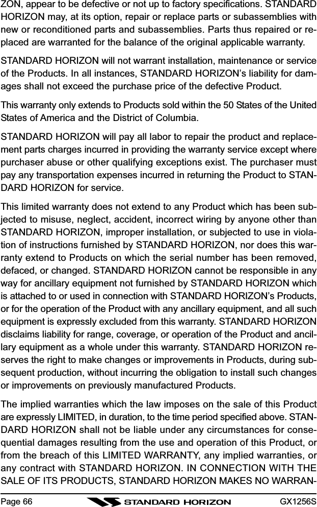
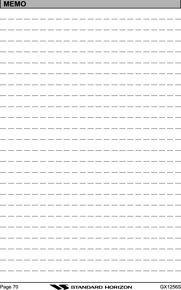
![GX1256S Page 91 GENERAL INFORMATIONThe STANDARD HORIZON QUEST+ is a VHF/FM transceiver designed foruse in the frequency range of 156.025 to 163.275 MHz. The GX1256S re-quires 13.8V for operation and has a switchable RF output power of 1 wattor 25 watts.The transceiver is capable of RTCM SC101 DSC (Digital Selective Calling)operation.The transceiver operates on all currently-allocated marine channels whichare switchable for use with either USA, International, or Canadian regula-tions. It has an emergency channel 16 which can be immediately selectedfrom any channel by pressing the red [16/9] key. NOAA Weather channelscan also be accessed immediately by pressing the [WX] key.Other features of the transceiver include: scanning, priority scanning, sub-mersible mic, high and low voltage warning, and GPS repeatability.](https://usermanual.wiki/Yaesu-Musen/30053X30/User-Guide-421472-Page-9.png)
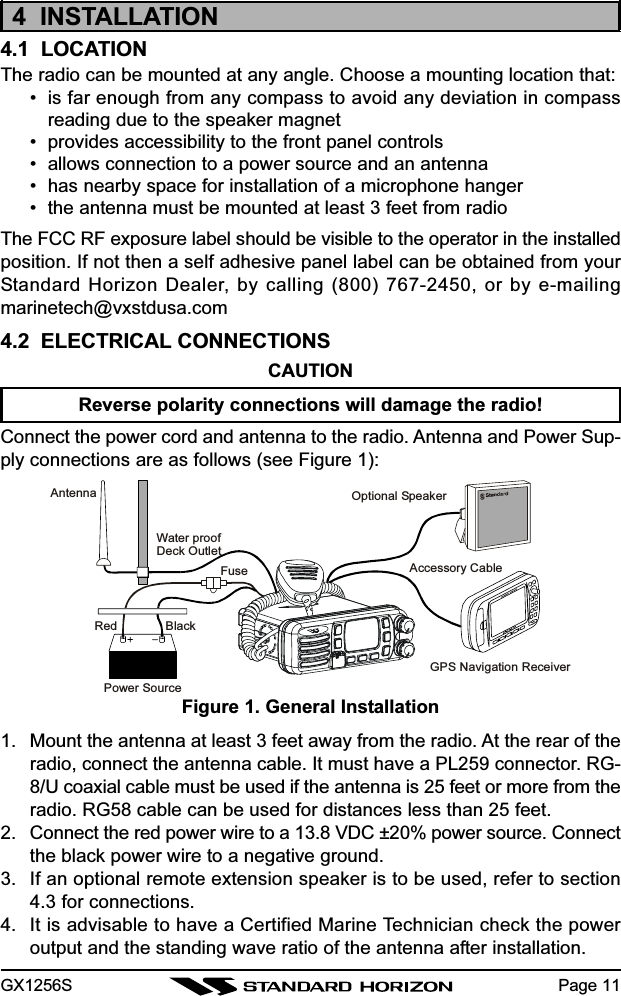
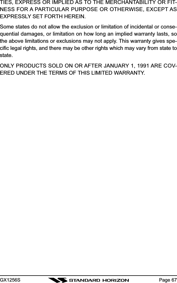
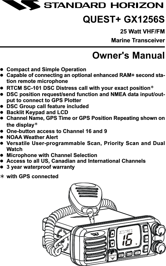
![GX1256S Page 134.4 CONNECTION OF GPS WITH NMEA OUTPUTAdditional Information:• The GPS must have the NMEA Output turned on and set to 4800 Baudin the setup menu. If there is a selection for parity select none.• For further information on interfacing /setting up your GPS. Please con-tact the manufacturer of the GPS receiver.•QUEST+ is corresponded with following NMEA sentence:• NMEA-0183 version 2.0 or higher• GLL, GGA, RMC and GNS (RMC sentence is recommended)If you have further inquires, please feel free to contact us at:Phone: (800) 767-2450Web site: standardhorizon.comEmail: marinetech@vxstdusa.com4.5 CHECKING GPS CONNECTIONAfter connections have been made between the QUEST+ and the GPS, asmall satellite icon will appear on the top right corner of the LCD display. Tosee additional GPS information press and hold the [H/L(POS)] key until theQUEST+ shows the Latitude and Longitude.NOTEThe QUEST+ may be setup to show Lat/Lon or time received from aconnected GPS. To setup and show time refer to Section 6.18.Manufacturer/ModelLowrance PortableMagellan Fixed MountMagellan PortableNorthstarRaytheon 420Raytheon 520 / 620Raytheon RL SERIESSimradSitex Neptune, NautilusWiresOrangeBlack (GND)GrayBlack (GND)OrangeBlack (GND)YellowBlack (GND)YellowBrownBlueBrownWhiteBrownWhiteBrownGrayBrownQUEST+BlueGreenBlueGreenBlueGreenBlueGreenBlueGreenBlueGreenBlueGreenBlueGreenBlueGreenWiresGreenBlueBrownWhiteBlueWhiteBlackBlueBlack (GND)BrownBlack (GND)YellowGreenGreenBlackWhiteBlackWhiteBlack (GND)Manufacturer/ModelSTANDARD HORIZONFuruno GP30, 36Furuno GP1650, 1850Garmin Fixed MountsGarmin PortablesJRC GPS500JRC 100 SERIESJRC 200 SERIESLowrance Fixed MountQUEST+GreenGrayBlueBlueGreenBlueGreenBlueGreenBlueGreenBlueGreenBlueGreenBlueGreenBlueGreen](https://usermanual.wiki/Yaesu-Musen/30053X30/User-Guide-421472-Page-13.png)
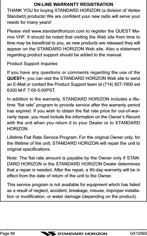
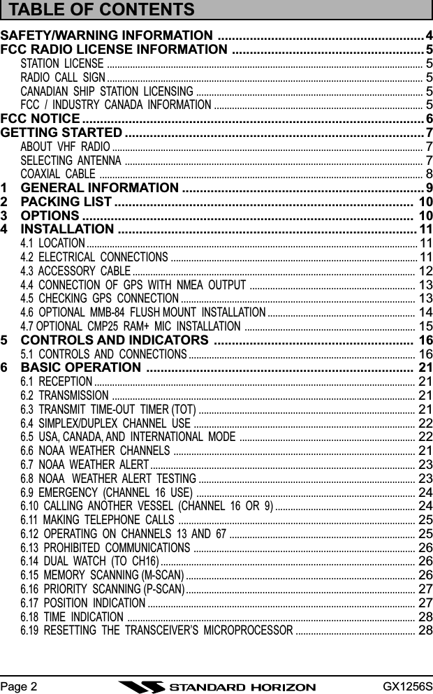
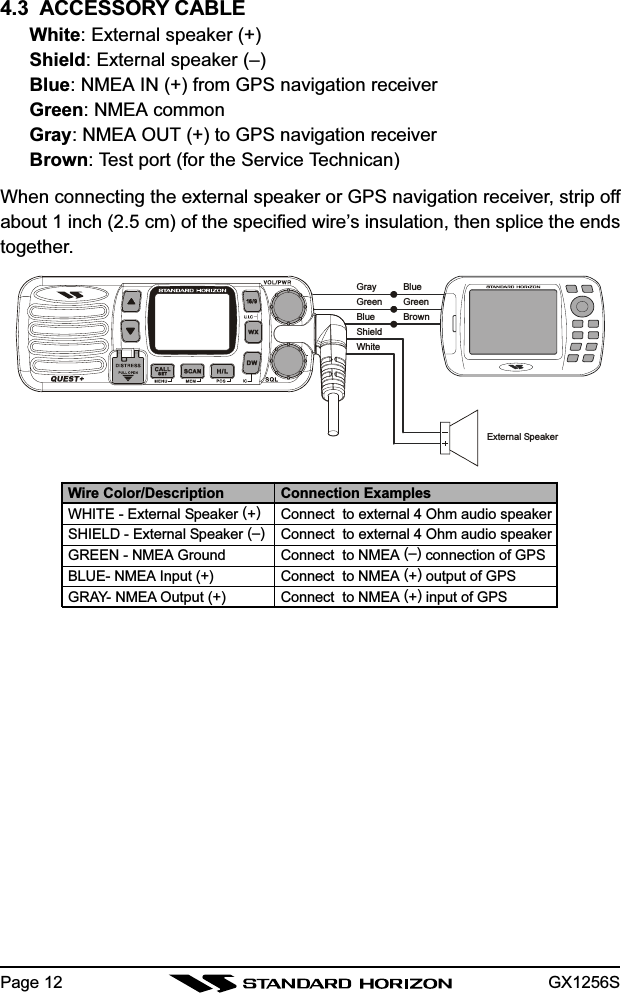
![GX1256SPage 165 CONTROLS AND INDICATORSNOTEThis section defines each control of the transceiver. See Figure 4 forlocation of controls. For detailed operating instructions refer to chapter6 of this manual.5.1 CONTROLS AND CONNECTIONSPOWER SWITCH/VOLUME CONTROLTurns the transceiver on and off as well as adjusts the audio volume. Toturn the transceiver on press and hold this knob until the LCD turns on.To turn it off, press and hold this knob until the LCD turns off. When thepower is turned on, the transceiver is set to the last selected channel.Secondary UseWhen the transceiver is turned on while the [SCAN(MEM)] and [WX]keys are held down, the internal microprocessor is reset. This clears thememory and all user-programmed settings, such as scan memory. Thiscondition is known as the default condition, the same as when shippedfrom the factory. For a list of these defaults, see the section on Resettingthe Transceiver’s Microprocessor.NOTEResetting the microprocessor will not erase DSC MMSI and Direc-tory Call information.SQUELCH CONTROL (SQL)Sets the point at which random noise on the channel does not activatethe audio circuits but a received signal does. This point is called thesquelch threshold. Further adjustment of the squelch control will degradereception of wanted transmissions.KEYPAD[16/9] KeyImmediately recalls channel 16 from any channel location. Holding downthis key recalls channel 9. Pressing the [16/9] key again reverts to theprevious selected working channel.Secondary usePlease see secondary use for the [WX] key.](https://usermanual.wiki/Yaesu-Musen/30053X30/User-Guide-421472-Page-16.png)
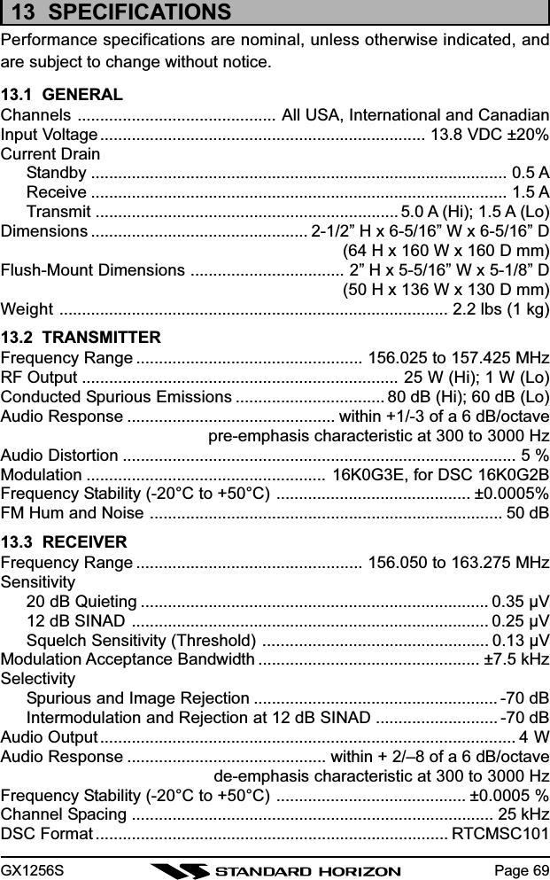
![GX1256SPage 18[WX] KeyImmediately recalls the previously selected NOAA weather channel fromany channel location.Secondary use1. Holding down the [16/9] key while pressing the [WX] key changesthe mode from USA to International or Canadian.2. Holding down the [WX] and [SCAN(MEM)] key while turning the poweron resets the microprocessor and erases scan channels from memory.This clears the memory and establishes the factory-set defaults. Fora list of these defaults, see the section on Resetting the Transceiver’sMicroprocessor.[DW(IC)] KeyWatches for a transmission on CH16 and another selected channel untileither signal is received. (Dual watch)NOTE: When the DSC SCANNING feature is enabled(see section 7.10DSC SCANNING), the radio watches for a transmission on CH16, an-other selected channel, and CH70 until either signal is received (Triplewatch).Secondary usePress and hold [DW(IC)] key, when the optional RAM+ Mic is connected,intercom operation will operate between radio and RAM+ Mic.[H/L(POS)] KeyToggles between high and low power. When the [H/L(POS)] key is pressedwhile the transceiver is on channel 13 or 67, the power will temporarilyswitch from LO to HI power until the PTT is released. The [H/L(POS)]key does not function on transmit inhibited and low power only channels.Secondary usePress and hold the [H/L(POS)] key to display the Position Data on theLCD, when connected to the GPS receiver.[SCAN(MEM)] Key1. Starts and stops scanning of programmed channels.2. If held while the [UP] or [DOWN] key on the microphone are pressedor [UP] or [DOWN] key on radio are pressed, the radio will show thechannels programmed in scan memory. This function will not work ifthe unit is scanning.NOTE: The priority channel is channel 16 only.](https://usermanual.wiki/Yaesu-Musen/30053X30/User-Guide-421472-Page-18.png)
![GX1256S Page 19[CALL/SET(MENU)] KeyThe [CALL/SET(MENU)] key functions as the enter key.Secondary usePress the [CALL/SET(MENU)] key to access the DSC OPERATIONmenu. The INDIVIDUAL and ALL SHIPS CALLS functions can be ac-cessed from the DSC OPERATION menu.Press and hold the [CALL/SET(MENU)] key to access the RADIO orDSC setup menu. The following functions can be accessed in the menu.[DISTRESS] KeyUsed to send a DSC Distress Call. To send the distress call see section6.2 (Sending a Distress Call).[UP] and [DOWN] KeysThe [UP] and [DOWN] keys are used to select a desired channel and toselect items in the DSC OPERATION and SETUP menus. The [UP] or[DOWN] key on the microphone can also be used to select channels.RADIO SETUP MENUDSC SETUP MENU](https://usermanual.wiki/Yaesu-Musen/30053X30/User-Guide-421472-Page-19.png)
![GX1256SPage 20RAM MIC CONNECTORConnects the QUEST+ to the enhanced RAM+ MIC (Remote AccessMicrophone). Refer to section 9 RAM+ MIC OPERATION.ACCESSORY CONNECTION CABLEConnects the radio to a GPS, and an external speaker.DC INPUT CABLEConnects the radio to a DC power supply of 13.8VANTENNA JACKConnects an antenna to the transceiver. Use a marine VHF antenna withan impedance of 50 ohms.PTT (Push-To-Talk) SWITCHKeys the transmitter.MICROPHONETransmits the voice message with reduction of background noise.[UP()] and [DOWN()] KEYSThe [UP()] and [DOWN()] on the microphone function the same asthe [UP] and [DOWN] key on the front panel of the transceiver.[16/9] KeyPressing the [16/9] key Immediately recalls channel 16 from any loca-tion. Press and hold the [16/9] key to recall channel 9. Pressing the[16/9] key again will revert the radio to the last channel selected.](https://usermanual.wiki/Yaesu-Musen/30053X30/User-Guide-421472-Page-20.png)
![GX1256S Page 216 BASIC OPERATION6.1 RECEPTION1. After the transceiver has been installed, ensure that the power supplyand antenna are properly connected.2. Press and hold the VOL/PWR knob until the radio turns on.3. Turn the SQL knob fully counterclockwise. This state is known as “squelchoff”.4. Turn up the VOL/PWR knob until noise or audio from the speaker is at acomfortable level.5. Turn the SQL knob clockwise until the random noise disappears. Thisstate is known as the “squelch threshold.”6. Press the [UP] or [DOWN] key to select the desired channel. Refer to thechannel chart on page 60 for available channels.7. When a message is received, adjust the volume to the desired listeninglevel. The “BUSY” indicator in the LCD is displayed indicating that thechannel is being used.6.2 TRANSMISSION1. Perform steps 1 through 6 of RECEPTION.2. Before transmitting, monitor the channel to ensure it is clear. THIS IS ANFCC REQUIREMENT!3. Press the PTT (push-to-talk) switch. The TX indicator on the LCD is dis-played.4. Speak slowly and clearly into the microphone.5. When the transmission is finished, release the PTT switch.NOTEThis is a noise-canceling microphone. The oval slot on the bottom ofmicrophone should be positioned within 1 inch (2.5 cm) from themouth for optimum performance.6.3 TRANSMIT TIME - OUT TIMER (TOT)When the PTT switch on the microphone is held down, transmit time is limitedto 5 minutes. This limits unintentional transmissions due to a stuck micro-phone. About 10 seconds before automatic transmitter shutdown, a warningbeep will be heard from the speaker(s). The transceiver will automatically goto receive mode, even if the PTT switch is continually held down. Before trans-mitting again, the PTT switch must first be released and then pressed again.](https://usermanual.wiki/Yaesu-Musen/30053X30/User-Guide-421472-Page-21.png)
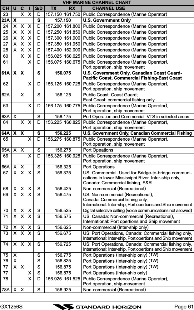
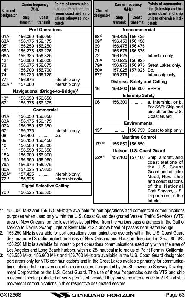
![GX1256SPage 226.4 SIMPLEX/DUPLEX CHANNEL USERefer to the VHF MARINE CHANNEL CHART (page 60) for instructions onuse of simplex and duplex channels.NOTEAll channels are factory-programmed in accordance with FCC (USA),Industry Canada (Canada), and International regulations. Mode of op-eration cannot be altered from simplex to duplex or vice-versa.6.5 USA, CANADA, AND INTERNATIONAL MODE1. To change the modes, hold the [16/9] key and press the [WX] key. Themode changes from USA to International to Canadian with each press ofthe [WX] key.2. “U” will be displayed on the LCD for USA mode, “I” will be displayed forInternational mode, and “C” will be displayed for Canadian mode.3. Refer to the VHF MARINE CHANNEL CHART (page 60) for allocatedchannels in each mode.6.6 NOAA WEATHER CHANNELS1. To receive a NOAA weather channel, press the [WX] key from any chan-nel. The transceiver will go to the last selected weather channel.2. Press the [UP] or [DOWN] key on the microphone or on front panel toselect a different NOAA weather channel.3. To exit from the NOAA weather channels, press the [WX] key. The trans-ceiver returns to the channel it was on prior to a weather channel.](https://usermanual.wiki/Yaesu-Musen/30053X30/User-Guide-421472-Page-22.png)
![GX1256S Page 236.7 NOAA WEATHER ALERTIn the event of extreme weather disturbances, such as storms and hurri-canes, the NOAA (National Oceanic and Atmospheric Administration) sendsa weather alert accompanied by a 1050 Hz tone and subsequent weatherreport on one of the NOAA weather channels. When the Weather Aleartfeature is enabled (see section 8.4 WEATER ALERT), the transceiver iscapable of receiving this alert if the following is performed:1. Program NOAA weather channels into the transceiver’s memory for scan-ning. Follow the same procedure as for regular channels under Section6.15.2. Press the [SCAN(MEM)] key once to start memory scanning or holddown the [SCAN(MEM)] key during memory scanning to start priorityscanning.3. The programmed NOAA weather channels will be scanned along withthe regular-programmed channels. However, scanning will not stop on anormal weather broadcast unless a NOAA alert is received.4. When an alert is received on a NOAA weather channel, scanning willstop and the transceiver will emit a loud beep to alert the user of a NOAAbroadcast.5. Press the [WX] key to stop the alert tone and receive the weather report.NOTEIf the [WX] key is not pressed the alert tone will be emitted for 5 minutesand then the weather report will be received.NOTEThe Weather Aleart feature is also engaged while the transceiver isreceived on the one of the NOAA weather channel.6.8 NOAA WEATHER ALERT TESTINGIn the event of a major storm or other appreciable weather condition requir-ing vessels at sea or other bodies of water to be notified, the NOAA (Na-tional Oceanographic and Atmospheric Administration) broadcasts a 1050Hz tone that some marine VHF radios can detect. (Refer to above section“NOAA WEATER ALERT” on how to use this feature.) This tone, when de-tected, will produce a loud beep from the radio speaker to signal that aweather alert is being broadcast.In order to test this system, the NOAA broadcasts the 1050 Hz tone everyWednesday, sometime between 11 AM and 1 PM.](https://usermanual.wiki/Yaesu-Musen/30053X30/User-Guide-421472-Page-23.png)
![GX1256SPage 26radio is programmed to automatically reduce power to this limit on thesechannels. However, in certain situations it may be necessary to temporarilyuse a higher power. See page 18 ([H/L(POS)] key) for means to temporarilyoverride the low-power limit on these two channels.6.13 PROHIBITED COMMUNICATIONSThe FCC prohibits the following communications:• False distress or emergency messages:• Messages to “any boat” except in emergencies and radio tests;• Messages to or from a vessel on land;• Transmission while on land;• Obscene, indecent, or profane language (potential fine of $10,000).6.14 DUAL WATCH (TO CH16)1. Adjust the SQL knob until the background noise disappears.2. Select the channel you wish to dual watch to Ch16.3. Press the [DW(IC)] key. The display will scan between CH16 and thechannel that was selected in step 2.If a transmission is received on the channel selected instep 2, the QUEST+ will dual watch to Ch16.4. To stop Dual Watch press the [DW(IC)] key again.6.15 MEMORY SCANNING (M-SCAN)NOTE• During scanning, the dot matrix area of the LCD will show M-SCAN orP-SCAN depending on the scan mode selected.• If GPS position is displayed this icon will be hidden.1. Adjust the SQL knob until background noise disappears.2. Select a desired channel to be scanned using the [UP] or [DOWN] key.Press and hold the [SCAN(MEM)] key, “MEM” will ap-pear on the LCD which indicates the channel has beenprogrammed into the transceivers memory.3. Repeat step 2 for all the desired channels to be scanned.4. To DELETE a channel from the transceiver’s memory,press and hold the [SCAN(MEM)] key, “MEM” will disappear in the LCD.5. To start scanning, press the [SCAN(MEM)] key. Scan-ning will proceed from the lowest to the highest pro-grammed channel number and will stop on a channelwhen a transmission is received.](https://usermanual.wiki/Yaesu-Musen/30053X30/User-Guide-421472-Page-26.png)
![GX1256S Page 27(Latitude) (Longitude)(No GPS Signal)6. The channel number will blink during reception.7. To stop scanning, press the [SCAN(MEM)], [16/9], [WX], or PTT key.6.16 PRIORITY SCANNING (P-SCAN)1. The priority channel is set to channel 16.2. For priority scanning during M-SCAN, press and holdthe [SCAN(MEM)] key, until P-SCAN appears in the LCD.Scanning will proceed between the memorized chan-nels and the priority channel. The priority channel willbe scanned after each programmed channel.: When DSC Scanning method is enabled. Default is DSC scan is ON.3. The scanning will be performed while receiving the MEMCH (memorized channel).4. To stop scanning, press the [SCAN(MEM)], [16/9], [WX],or PTT key.NOTETriple watch (T/W) means the radio is watching CH70 for DSC Calls.Dual watch (D/W) means the radio is not watching CH70 for DSC Calls.6.17 POSITION INDICATIONThe transceiver has the ability to display the vessel’s position (LAT/LON) forConfirmation of the data, if connected to a GPS receiver.1. Press and hold the [H/L(POS)] key, dis-plays “LAT” and “LON” information al-ternately every two seconds.If the GPS receiver receives no signal,the display will be as shown in the illus-tration.2. To hide the position information, press and hold the[H/L(POS)] key again.MEM CH. CH. 16 CH. 70 MEM CH. CH. 16 CH. 70](https://usermanual.wiki/Yaesu-Musen/30053X30/User-Guide-421472-Page-27.png)
![GX1256SPage 286.18 TIME INDICATIONPress and hold the [16/9] and [H/L(POS)] keys while turn-ing the transceiver on, the transceiver will display the TIMEon the upper side, if connected to a GPS receiver.NOTEThe TIME OFFSET should be set to local time in the DSC/RADIO setupmode when the radio is connected the GPS navigation receiver. To ad-just TIME OFFSET to your local time, refer to section 7.6 TIME OFF-SET.6.19 RESETTING THE TRANSCEIVER’S MICROPROCESSORResetting the microprocessor restores the initial, factory supplied conditionsin the transceiver. These are called the default conditions.To reset the microprocessor, first turn the transceiver off. Then while press-ing the [WX] and [SCAN(MEM)] keys, turn the transceiver on. The defaultconditions are:• No channels in SCAN memory.• Channel 16 will be selected when the transceiver is turned on.• WX channel 01 will be recalled when the [WX] key is pressed.• Key beep will be on.NOTEResetting the microprocessor will not erase DSC MMSI and Directoryinformation.](https://usermanual.wiki/Yaesu-Musen/30053X30/User-Guide-421472-Page-28.png)

![GX1256SPage 307.2 DSC SCANWhen the radio is shipped from the factory it is programmed so CH70 (theDSC channel) is scanned at all times. There is a selection in the SETUPMENU to disable the DSC SCAN. However, turning off DSC SCAN will dis-able the radio from receiving DSC calls i.e.: Individual Call, All Ships Call,Distress Call and Position Requests. If you want to use any of the functionsthe selection must be left ON.To Change DSC SCAN Method:1. Press and hold down the [CALL/SET(MENU)] key until“RADIO SETUP” appears.2. Press the [DOWN] key to select “DSC SETUP.”3. Press the [CALL/SET(MENU)] key, then press the [UP]or [DOWN] key to select “DSC SCAN.”4. Press the [CALL/SET(MENU)] key to enable setting thisitem (The number in the display will flash).5. Press the [UP] or [DOWN] key to select “on” or “oF (off).”6. Press the [CALL/SET(MENU)] key to store the selectedsetting.7. Press the [UP] or [DOWN] key to select “EXIT,” thenpress the [CALL/SET(MENU)] key.8. Press the [UP] or [DOWN] key to select “EXIT,” thenpress the [CALL/SET(MENU)] key to return to the nor-mal operation.](https://usermanual.wiki/Yaesu-Musen/30053X30/User-Guide-421472-Page-30.png)
![GX1256S Page 317.3 USCG DSC WATCHThe USCG has plans to upgrade its VHF National Distress System (expectedby 2005), so at the time of printing only larger vessels that are required tocarry VHF DSC radios will be able to hear your distress transmission.7.3.1 Maritime Mobile Service Identity (MMSI)What is an MMSI?An MMSI is a nine digit number used on Marine Transceivers capable ofusing Digital Selective Calling (DSC). This number is used like a telephonenumber to selectively call other vessels.NOTETHIS NUMBER MUST BE PROGRAMMED INTO THE RADIO TO OP-ERATE THE QUEST+ DSC FUCTIONS.How can I obtain an MMSI assignment?Boat US offers free MMSI numbers. Visit the following to register:http://www.boatus.com/mmsi/.7.3.2 Programming the MMSINOTEUser MMSI can be input only twice. If the user tries to input MMSI morethan twice, the radio will show the display on the right.If the user needs to change the MMSI more than twice,the transceiver will have to be sent to Factory Service.Refer to the section 10.2 FACTORY SERVICE.1. Press and hold down the [CALL/SET(MENU)] key until“RADIO SETUP” appears.2. Press the [DOWN] key to select “DSC SET.”3. Press the [CALL/SET(MENU)] key, then press the[DOWN] key to select “USER MMSI.”4. Press the [CALL/SET(MENU)] key to enable setting thisitem (The number in the display will flash).5. Press the [UP] or [DOWN] key to select first number ofyour MMSI, then press the [CALL/SET(MENU)] key todefine the setting.6. Repeat above step to set your MMSI (up to 9 digits).When the last number of your MMSI is in place, pressand hold the [CALL/SET(MENU)] key to store your MMSI.](https://usermanual.wiki/Yaesu-Musen/30053X30/User-Guide-421472-Page-31.png)
![GX1256SPage 327. Press the [DOWN] key to select “EXIT,” then press the[CALL/SET(MENU)] key.8. Press the [UP] or [DOWN] key to select “EXIT,” thenpress the [CALL/SET(MENU)] key to return to the nor-mal operation.7.4 ADDITIONAL DIGITAL SELECTIVE CALLING INFORMATIONFor additional information the USCG has an excellent site that should bevisited at www.navcen.uscg.mil/marcoms/gmdss/dsc.html.7.5 DSC DISTRESS CALLThe QUEST+ is capable of transmitting and receiving DSC Distress mes-sages to all DSC radios. The QUEST+ may be connected to a GPS to alsotransmit the Latitude, Longitude of the vessel.7.5.1 Transmitting A DSC Distress CallNOTETo be able to transmit a DSC distress call a MMSI number must beprogrammed, refer to section 7.3.2 Programming the MMSIIn order for your ships location to be transmitted a GPS must be connectedto the QUEST+, refer to section 4.4 CONNECTION OF GPS WITH NMEAOUTPUT.1. Lift the red spring loaded DISTRESS cover and pressthe [DISTRESS] key. The “DISTRESS” will appear onthe LCD.2. Press and hold the [DISTRESS] key. The LCD will countdown (3, 2, 1) following this the QUEST+ will transmitthe Distress Call.3. When the distress signal is sent, the “TX” icon will ap-pear on the LCD. After the message has been sent, theDistress Alarm will sound.4. The transceiver “shadow-watches” for a transmissionbetween CH16 and CH70 until an acknowledgment sig-nal is received. “RECEIVED ACK” will scroll on the LCD.](https://usermanual.wiki/Yaesu-Musen/30053X30/User-Guide-421472-Page-32.png)
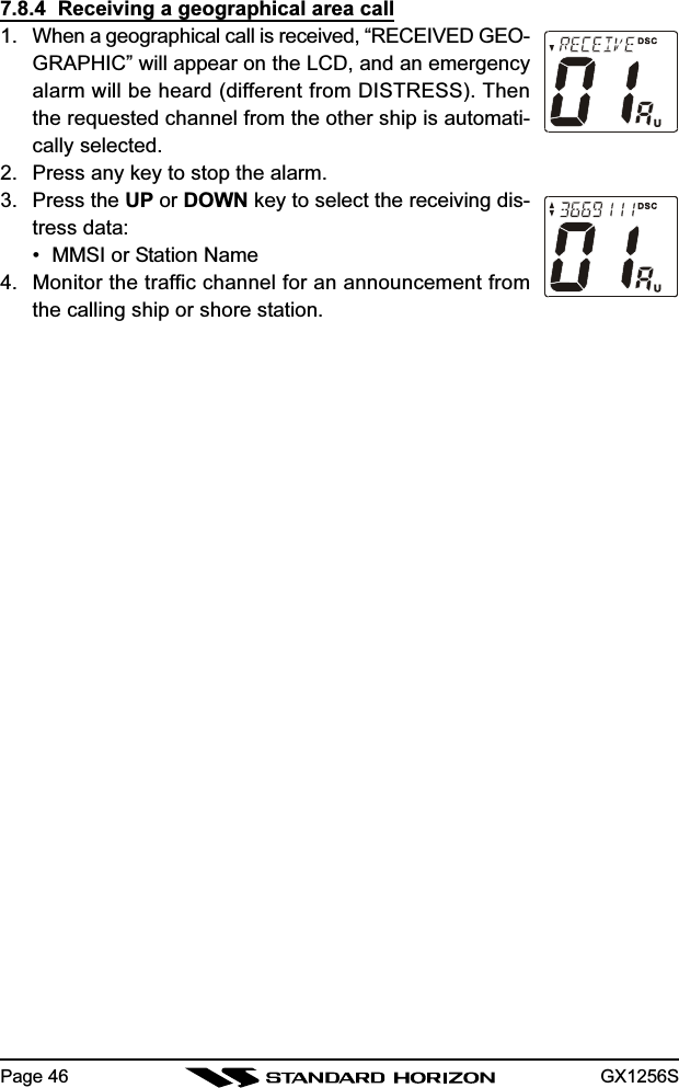
![GX1256S Page 335. If no acknowledgment is received, the distress call is repeated in 3.5 to4.5 minute intervals until an acknowledgment is received.6. To cancel a Distress Call1) Press the [16/9] key2) Press the [WX] key3) Turn off the radio4) Press the [DISTRESS] key, then press the [UP] or [DOWN] key until“CANCEL” is shown on the LCD. Press the [CALL/SET(MENU)] key.7. When a distress acknowledgment is received, a distress alarm soundsand channel 16 is automatically selected.8. To cancel the alarm, press any key.NOTEIf the radio is receiving on a working channel or transmitting on a work-ing channel, DSC calls will not be received.7.5.2 Receiving a distress call1. A distress call is received. “RECEIVED DISTRESS” willappear on the LCD, and an emergency alarm will be heard.Channel 16 is automatically selected.2. Press any key to stop the alarm.3. Press the [UP] or [DOWN] key to select the receivingdistress data:• MMSI or Station Name • TIME (UTC)• Latitude • LongitudeNOTE• If the received distress data does not include the position data, “NOPOSITION DATA” will scroll on the LCD.• You must continue monitoring channel 16 as a coast station may re-quire assistance in any rescue attempt.](https://usermanual.wiki/Yaesu-Musen/30053X30/User-Guide-421472-Page-33.png)
![GX1256SPage 347.5.3 Receiving a distress relay call1. A distress relay call is received. “RECEIVED RLY” willappear on the LCD, and an emergency alarm will beheard.Channel 16 is automatically selected.2. Press any key to stop the alarm.3. Press the [DOWN] key to appear the receiving distressdata (MMSI or Station Name).NOTEYou must continue monitoring channel 16 as a coast station may re-quire assistance in any rescue attempt.7.6 ALL SHIPS CALLThe All Ships Call function allows contact to be established with other vesselstations without having their ID in the individual calling directory.Also, priority for the call can be designated as Urgency, Safety or Routine.URGENCY Call: This type of call is used when a vessel may not truly be indistress, but have a potential problem that may lead to adistress situation (PAN, PAN,Call Type).SAFETY Call: Used to transmit boating safety information to other ves-sels (Security Call Type).This message usually contains information about an overdue boat, debris inthe water. Loss of a navigation aid or an important meteorological message.7.6.1 Transmitting An All Ships Call1. Select the traffic channel (for voice communication).2. Press the [CALL/SET(MENU)] key.3. Press the [DOWN] key to select “ALL SHIPS.”4. Press the [CALL/SET(MENU)] key again.5. Press the [DOWN] key to select the nature of call (“UR-GENCY,” or “SAFETY”).6. Press the [CALL/SET(MENU)] key to transmit the se-lected type of ALL SHIPS DSC call.7. After the ALL SHIPS CALL is transmitted, the transceiverwill wait on CH16. Call has been transmited.](https://usermanual.wiki/Yaesu-Musen/30053X30/User-Guide-421472-Page-34.png)
![GX1256S Page 357.6.2 Receiving An All Ships Call1. An all ships call is received. “RECEIVED ALL SHIPS”will appear on the LCD, and an emergency alarm will beheard.Channel 16 is automatically selected.2. Press any key to stop the alarm.3. Press the [UP] or [DOWN] key to select the receivingdistress data:• MMSI or Station Name4. Monitor channel 16 or traffic channel until the communi-cation is completed.7.7 INDIVIDUAL CALLThis feature allows the user to contact another user vessel with a DSC radioand automatically switch the receiving DSC radio to a desired working chan-nel. This feature is similar to calling a vessel on CH16 and requesting to goto a another channel.7.7.1 Setting up the Individual / Position Call DirectoryThe QUEST+ has a DSC directory that allows you to store a vessel or per-son names and the MMSI number associated with vessels you wish to trans-mit Individual calls, Position Requests and Position Send transmissions.To transmit an Individual call you must program this directory with informa-tion of the persons you wish to call, similar to a cellular phones telephonedirectory.1. Press and hold down the [CALL/SET(MENU)] key until “RADIO SETUP”appears.2. Press the [DOWN] key to select “DSCSETUP”.3. Press the [CALL/SET(MENU)] key toselect “INDIVIDUAL DIRECTORY.”4. Press the [CALL/SET(MENU)] key toselect “ADD.”5. Press the [CALL/SET(MENU)] key to enable setting thisitem.6. Press the [UP] or [DOWN] key to select a first characterof the Station Name, then press the [CALL/SET(MENU)]](https://usermanual.wiki/Yaesu-Musen/30053X30/User-Guide-421472-Page-35.png)
![GX1256SPage 36key to move to next character.7. Repeat step 6 as many times as necessary to completethe Station Name (up to 12 characters).8. Press and hold the [CALL/SET(MENU)] key to store theStation Name and enable setting the MMSI ID code.9. Press the [UP] or [DOWN] key to select the first digit ofthe MMSI ID code, the press the [CALL/SET(MENU)]key to move to next character.10. Repeat step 9 as many times as necessary to completethe MMSI ID code (9 digits).11. Press and hold the [CALL/SET(MENU)] key to store theMMSI ID code.12. Press the [DOWN] key to select “EXIT,” then press the[CALL/SET(MENU)] key.13. Press the UP or [DOWN] key to select “EXIT,” then pressthe [CALL/SET(MENU)] key to return to the normal op-eration.7.7.2 Setting up Individual ReplyAllows setting up the radio to automatically (default setting) or manuallyrespond to a DSC Individual call requesting you to switch to a working chan-nel for voice communications. When Manual is selected the MMSI of thecalling vessel is shown allowing you to see who is calling. This function issimilar to caller id on a cellular phone.1. Press and hold down the [CALL/SET(MENU)] key until “RADIO SETUP”appears.2. Press the[DOWN] key to select “DSCSETUP.”3. Press the [CALL/SET(MENU)] key, thenpress the [UP] or [DOWN] key to select“INDIVIDUAL REPLY.”4. Press the [CALL/SET(MENU)] key to enable setting thisitem.5. Press the [UP] or [DOWN] key to select “AU (Automatic)”or “oF (off).”6. Press the [CALL/SET(MENU)] key to store the selectedsetting.7. Press the [UP] or [DOWN] key to select “EXIT,” then](https://usermanual.wiki/Yaesu-Musen/30053X30/User-Guide-421472-Page-36.png)
![GX1256S Page 37press the [CALL/SET(MENU)] key.8. Press the [UP] or [DOWN] key to select “EXIT,” thenpress the [CALL/SET(MENU)] key to return to the nor-mal operation.7.7.3 Setting up Individual Call RingerWhen a Individual call is received the radio will produce a ringing tone for 3minutes. This selection allows the Individual Call ringer time to be changed.1. Press and hold down the [CALL/SET(MENU)] key until“RADIO SETUP” appears.2. Press the [DOWN] key to select “DSC SETUP.”3. Press the [CALL/SET(MENU)] key, then press the [UP]or [DOWN] key to select “INDIVIDUAL RINGER.”4. Press the [CALL/SET(MENU)] key to enable setting thisitem.5. Press the [UP] or [DOWN] key to select ringing time of aINDIVIDUAL CALL.4:3 minutes continuously3:15 times2:10 times1:5 times6. Press the [CALL/SET(MENU)] key to store the selectedringing time.7. Press the [UP] or [DOWN] key to select “EXIT,” thenpress the [CALL/SET(MENU)] key.8. Press the [UP] or [DOWN] key to select “EXIT,” thenpress the [CALL/SET(MENU)] key to return to the nor-mal operation.7.7.4 Transmitting an Individual CallThis feature allows the user to contact another vessel with a DSC radio. Thisfeature is similar to calling a vessel on CH16 and requesting to go to an-other channel. Select the traffic channel for voice communication.1. Select the traffic channel for voice communication.2. Press the [CALL/SET(MENU)] key.3. Press the [CALL/SET(MENU)] key again. The individualaddress will appear.4. Press the [UP] or [DOWN] key to select the individual you want to con-](https://usermanual.wiki/Yaesu-Musen/30053X30/User-Guide-421472-Page-37.png)
![GX1256SPage 38tact.5. To cancel, if needed, press the [UP] or [DOWN] key un-til the “EXIT” icon appear. Then press the [CALL/SET(MENU)] key. This procedure can be also canceledby pressing the WX or 16/9 key.6. Press the [CALL/SET(MENU)] key to transmit the individual DSC signal.7. After an INDIVIDUAL CALL is transmitted, the transceiver will wait 8 sec-onds for the acknowledgment. If the reply signal is not received, thetransceiver will transmit again.8. After the second INDIVIDUAL CALL is transmitted, if thereply signal is not received, “NO REPLY” icon will ap-pear on the LCD to prompt the user to send the callagain or exit the mode.9. When an individual call acknowledgment “able to com-ply” is received, the established channel is automatically selected andan alarm sounds.10. When an individual call acknowledgment with “unable to comply” is re-ceived, the established channel is automatically selected.7.7.5 Receiving an Individual CallWhen receiving an individual call, an acknowledgment must be sent back tothe calling station. Please refer to a selection in the 7.2.2 “Setting up Indi-vidual Reply” that allows the acknowledgment to be transmitted manually orautomatically.Automatic Reply:1. An individual call is received. “RECEIVED INDIVIDUAL” will appear onthe LCD, and an individual call alarm sounds. Then theradio automatically switches to the requested channel.2. Press any key to stop the alarm, then acknowledgmentis transmitted automatically.3. Press the PTT on the microphone and talk to the calling ship.Manual Reply:1. An individual call is received. “RECEIVED INDIVIDUAL”will appear on the LCD, and an individual call alarmsounds. Then the radio automatically switches to therequested channel.2. Press any key to stop the alarm.](https://usermanual.wiki/Yaesu-Musen/30053X30/User-Guide-421472-Page-38.png)
![GX1256S Page 393. Select type of reply function “ABLE” or “UNABLE” byusing the [UP] or [DOWN] key. In the Automatic mode,the acknowledgment is transmitted automatically.4. Press the PTT on the microphone and talk to the callingship.7.7.6 Setting Up the Call Waiting FunctionAllows the QUEST+ to be setup to reply (ABLE) or set the radio so it trans-mits a call that advises to the vessel the person is UNABLE to reply to thecall at this time. This function is similar to a answering machine. When setup in UNABLE and a individual call is received the Individual call from theother vessel is logged in the CALL WAITING directory for you to review andcall back at a later time.1. Press and hold down the [CALL/SET(MENU)] key until“RADIO SETUP” appears.2. Press the [DOWN] key to select “DSC SETUP.”3. Press the [CALL/SET(MENU)] key, then press the [UP]or [DOWN] key to select “INDIVIDUAL ACK.”4. Press the [CALL/SET(MENU)] key to enable setting thisitem.5. Press the [UP] or [DOWN] key to select “Ab (Able)” or“Un (Unable).”6. Press the [CALL/SET(MENU)] key to store the selectedsetting.7. Press the [UP] or [DOWN] key to select “EXIT,” thenpress the [CALL/SET(MENU)] key.8. Press the [UP] or [DOWN] key to select “EXIT,” thenpress the [CALL/SET(MENU)] key to return to the nor-mal operation.](https://usermanual.wiki/Yaesu-Musen/30053X30/User-Guide-421472-Page-39.png)
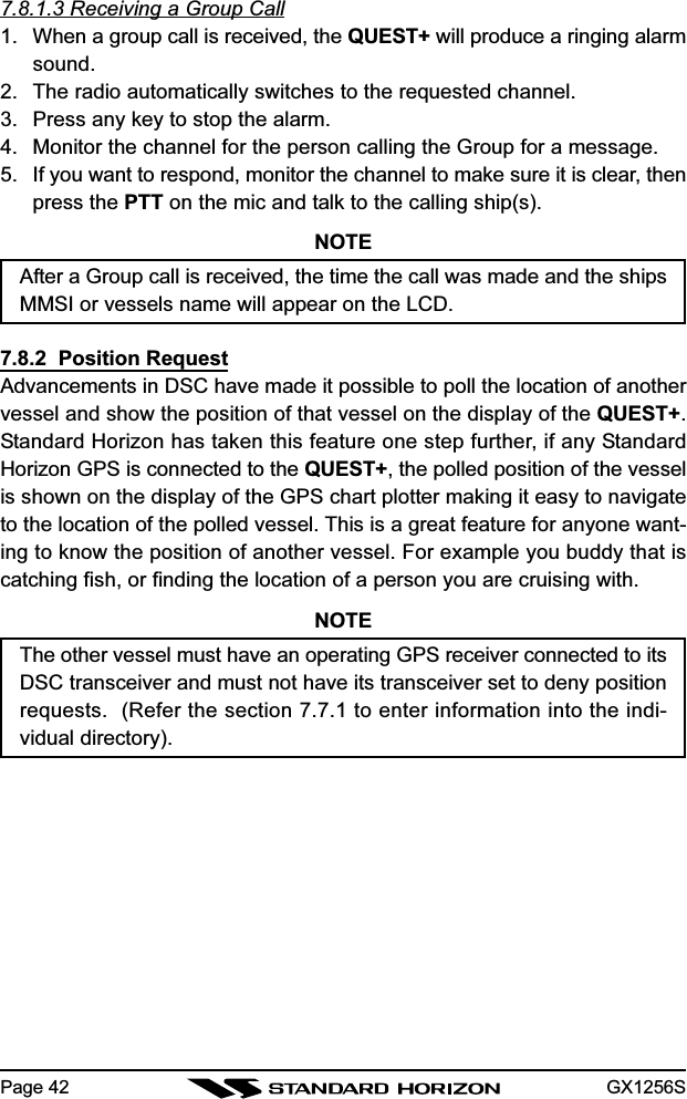
![GX1256SPage 407.8 ADVANCED DSC CALLS7.8.1 Group CallThis feature allows the user to contact a group of specific vessels (examplemembers of a yacht club) using DSC radios with Group call function to auto-matically switch to a desired channel for voice communications.7.8.1.1 Setup a Group CallFor this function to operate the same Group MMSI must be programmedinto all the DSC VHF radios within the group of vessels that will be using thisfeature. The group MMSI is a 9 digit (first digit permanently set to “0”) thatwill allow other radios to call your vessel along with others to automaticallyswitch to a working channel for voice communications. This function is veryuseful for yacht clubs and vessels traveling together that want to collectivelymake announcements on a predetermined channel.1. Press and hold down the [CALL/SET(MENU)] key until“RADIO SETUP” appears.2. Press the [DOWN] key to select “DSC SETUP.”3. Press the [CALL/SET(MENU)] key, then press the[DOWN] key to select “GROUP DIR.”4. Press the [CALL/SET(MENU)] key to enable setting thisitem.5. Press the [UP] or [DOWN] key to select “ADD,” thenpress the [CALL/SET(MENU)] key.6. Press the [UP] or [DOWN] key to select the first letter ofthe name of the group you want to reference in the di-rectory.7. Press the [CALL/SET(MENU)] key to store the first let-ter in the name. Press the [CALL/SET(MENU)] key tomove the cursor one space to the right.8. Repeat step 6 and 7 until the name is complete. Thename can consist of up to eleven characters, if you donot use all eleven characters press the [CALL/SET(MENU)] key to move to the next space. This methodcan also be used to enter a blank space in the name. Toclear the previous letter, press the [H/L(POS)] key.9. After the eleventh letter or space has been entered, pressand hold the [CALL/SET(MENU)] key to advance to theGROUP MMSI (Maritime Mobile Service Identity Num-](https://usermanual.wiki/Yaesu-Musen/30053X30/User-Guide-421472-Page-40.png)
![GX1256S Page 41ber) number entry.10. Press the [UP] or [DOWN] key to scroll through num-bers, 0-9.11. To enter the desired number and move one space tothe right press the [CALL/SET(MENU)] key. Repeat pro-cedure until all nine spaces of MMSI number are en-tered.12. If a mistake was made entering in the name or the MMSInumber repeat pressing the [CALL/SET(MENU)] keyuntil the wrong character is selected, then press the [UP]or [DOWN] key to correct the entry.13. To store the data entered, press and hold the [CALL/SET(MENU)] key.14. To enter another individual address, repeat steps 4 through 13.15. To exit this menu and return to radio operation mode press the [16/9]key.7.8.1.2 Transmitting a Group Call1. Select the desired channel to use Group Call for voicecommunications.2. Press the [CALL/SET(MENU)] key.3. Press the [DOWN] key to select “GROUP.” (To cancel,select “EXIT” with the [UP] or [DOWN] key or press [16/9] key.)4. Press the [CALL/SET(MENU)] key to enable setting thisitem.5. Press the [UP] or [DOWN] key to select the “Group” youwant to contact.6. Press the [CALL/SET(MENU)] key to transmit the GroupCall signal.7. When the Group Call signal is sent, the LCD will be asshown in the illustration at the right.8. After the GROUP CALL is transmitted, all the radios inthe group will switch to the designated channel.9. Listen to the channel to make sure it is not busy, thenkey the microphone and call the other vessels you de-sire to communicate with.](https://usermanual.wiki/Yaesu-Musen/30053X30/User-Guide-421472-Page-41.png)
![GX1256S Page 437.8.2.1 Setting up Position ReplyThe QUEST+ can be set up to automatically or manually send your positionto another vessel. This selection is important if you are concerned aboutsomeone polling the position of your vessel that you may not want to. In themanual mode you will see the MMSI or persons name shown on the displayallowing you to choose to send your position to the requesting vessel.1. Press and hold down the [CALL/SET(MENU)] key until“RADIO SETUP” appears.2. Press the [DOWN] key to select “DSC SETUP.”3. Press the [CALL/SET(MENU)] key, then press the [UP]or [DOWN] key to select “POS REPLY.”4. Press the [CALL/SET(MENU)] key to enable setting thisitem.5. Press the [UP] or [DOWN] key to select “AU (Automatic)”or “oF (off).” In “AU” mode, after a DSC POS Request isreceived, the radio will automatically transmit your ves-sels position. In “oF” mode, the display of the QUEST+will show who is requesting the position.6. Press the [CALL/SET(MENU)] key to store the selectedsetting.7. To exit this menu and return to radio operation mode pressthe [16/9] key.7.8.2.2 Transmitting a Position Request to Another VesselNOTETo transmit a Position Request, you must setup the QUEST+ DSC Indi-vidual / Position Call Directory with the name of the vessel(s) or personand the MMSI of the DSC radio you wish to poll. To setup this directoryrefer to section 7.7.1 Setting up the Individual / Position Call Directory1. Press the [CALL/SET(MENU)] key.2. Press the [DOWN] key to select “POS REQUEST.”3. Press the [CALL/SET(MENU)] key to show the IndividualDirectory.4. Press the [UP] or [DOWN] to select a name.5. Press the [CALL/SET(MENU)] key to transmit the posi-tion request DSC call.6. After a DSC position request is transmitted, the trans-](https://usermanual.wiki/Yaesu-Musen/30053X30/User-Guide-421472-Page-43.png)
![GX1256SPage 44ceiver remains on channel 70 until position data is re-ceived from the polled vessel.7. When the QUEST+ receives the position from the polledvessel it is shown on the radio display and also trans-ferred to the GPS Chart plotter.8. If the QUEST+ does not receive a reply, the LCD willdisplay “NO REPLY.” Press the [DOWN] key and select“SEND” to transmit the call again or “EXIT” to exit thePosition Request mode.NOTEIf the QUEST+ does not receive position data from the polled vessel,the LCD will show “NO POSITION DATA.”7.8.2.3 Receiving a Position RequestWhen a position request call is received from another vessel, a ringing alarmwill sound and POS REQUEST will be show in the LCD. Operation andtransceiver function differs depending on “POS REPLY” in the “DSC SETUP”menu setting.Automatically reply:1. When a position request call is received, a calling alarm sounds 4 times.Then requested position coordinates are transmittedautomatically to the vessel requesting your vessels po-sition.2. To exit from position request display, press any key.Manually reply:1. When a position request call is received, “RECEIVED POS REQUEST”will appear on the LCD, and a calling alarm will sound.2. Press the any key to disable the calling alarm.3. Select type of reply function “ABLE” or “EXIT” by usingthe [UP] or [DOWN] key.4. When “ABLE” is selected, press the [CALL/SET(MENU)]key. And the requested position coordinates will be trans-mitted.5. To exit from position request display, press any key.](https://usermanual.wiki/Yaesu-Musen/30053X30/User-Guide-421472-Page-44.png)
![GX1256S Page 457.8.3 Position SendThe feature is similar to Position Request, however instead of requesting aposition of another vessel this function allows you to send your position toanother vessel. Your vessel must have an operating GPS receiver connectedfor the QUEST+ to send the position.NOTETo transmit a Position Send Call, you must setup the QUEST+ DSCIndividual / Position Call Directory with the name of the vessel(s) orperson and the MMSI of the DSC radio you wish to send your positionto. To setup this directory refer to section 7.7.1 Setting up the Individual/ Position Call Directory.7.8.3.1 Transmitting a DSC Position Send Call1. Press the [CALL/SET(MENU)] key.2. Press the [DOWN] key to select the “POS SEND.”3. Press the [CALL/SET(MENU)] key, then press the [UP]or [DOWN] key to select a name in the directory.4. Press the [CALL/SET(MENU)] key to send your posi-tion to the selected vessel.7.8.3.2 Receiving a DSC Position Send CallWhen another vessel transmits their vessels location to the QUEST+ thefollowing will happen:1. A ringing sound will be produced when the call is received.2. Press the [16/9] key to stop ringing3. The position from the vessel sending it's position will be shown on thedisplay of the radio and also transferred to any Standard Horizon GPSChart plotter if connected.](https://usermanual.wiki/Yaesu-Musen/30053X30/User-Guide-421472-Page-45.png)
![GX1256S Page 478. RADIO SETUP MODE8.1 LAMP ADJUSTING1. Press and hold down the [CALL/SET(MENU)] key until“RADIO SETUP” appears.2. Press the [CALL/SET(MENU)] key to select “LAMP.”3. Press the [CALL/SET(MENU)] key to enable adjustingthis item (The number in the display will flash).4. Press the [UP] or [DOWN] key to select the desired level.3:High2:Mid1: Low0:OFF5. Press the [CALL/SET(MENU)] key to store the selectedlevel.6. Press the [DOWN] key to select “EXIT,” then press the[CALL/SET(MENU)] key.7. Press the [DOWN] key to select “EXIT,” then press the[CALL/SET(MENU)] key to return to the normal opera-tion.8.2 LCD CONTRAST ADJUSTING1. Press and hold down the [CALL/SET(MENU)] key until“RADIO SETUP” appears.2. Press the [CALL/SET(MENU)] key, then press the[DOWN] key to select “CONTRAST.”3. Press the [CALL/SET(MENU)] key to enable adjustingthis item (The number in the display will flash).4. Press the [UP] or [DOWN] key to adjust the contrast.Available values are 7 “dark” through 0 “light.”5. Press the [CALL/SET(MENU)] key to store the selectedlevel.6. Press the [DOWN] key to select “EXIT,” then press the[CALL/SET(MENU)] key.7. Press the [DOWN] key to select “EXIT,” then press the[CALL/SET(MENU)] key to return to the normal opera-tion.](https://usermanual.wiki/Yaesu-Musen/30053X30/User-Guide-421472-Page-47.png)
![GX1256SPage 488.3 KEY BEEP (ON or OFF)1. Press and hold down the [CALL/SET(MENU)] key until“RADIO SETUP” appears.2. Press the [CALL/SET(MENU)] key, then press the[DOWN] key to select “KEY BEEP.”3. Press the [CALL/SET(MENU)] key to enable adjustingthis item (The number in the display will flash).4. Press the [UP] or [DOWN] key to select “on” or “oF (off).”5. Press the [CALL/SET(MENU)] key to store the selectedsetting.6. Press the [DOWN] key to select “EXIT,” then press the[CALL/SET(MENU)] key.7. Press the [DOWN] key to select “EXIT,” then press the[CALL/SET(MENU)] key to return to the normal opera-tion.8.4 WEATHER ALERT (ON or OFF)1. Press and hold down the [CALL/SET(MENU)] key until“RADIO SETUP” appears.2. Press the [CALL/SET(MENU)] key, then press the[DOWN] key to select “WX ALT.”3. Press the [CALL/SET(MENU)] key to enable adjustingthis item (The number in the display will flash).4. Press the [UP] or [DOWN] key to select “on” or “oF (off).”5. Press the [CALL/SET(MENU)] key to store the selectedsetting.6. Press the [DOWN] key to select “EXIT,” then press the[CALL/SET(MENU)] key.7. Press the [DOWN] key to select “EXIT,” then press the[CALL/SET(MENU)] key to return to the normal opera-tion.](https://usermanual.wiki/Yaesu-Musen/30053X30/User-Guide-421472-Page-48.png)
![GX1256S Page 498.5 CHANNEL NAME CHANGE1. Press and hold down the [CALL/SET(MENU)] key until“RADIO SETUP” appears.2. Press the [CALL/SET(MENU)] key, then press the[DOWN] key to select “CH NAME.”3. Press the [CALL/SET(MENU)] key, then press the [UP]or [DOWN] key to select the channel on which you wishto change a name.4. Press the [CALL/SET(MENU)] key to enable adjustingthis item.5. Press the [UP] or [DOWN] key to select the first charac-ter (letter, number, or symbol) in the name you wish tostore, the press the [CALL/SET(MENU)] key to move tothe next character.6. If you make a mistake, press the [H/L(POS)] key to moveback, then re-select the correct letter, number, or sym-bol.7. Repeat step 5 as many times as necessary to completethe name tag (up to 12 characters).8. Press and hold the [CALL/SET(MENU)] key to store thenew name.9. Press the [DOWN] key to select “EXIT,” then press the[CALL/SET(MENU)] key.10. Press the [DOWN] key to select “EXIT,” then press the[CALL/SET(MENU)] key to return to the normal opera-tion.](https://usermanual.wiki/Yaesu-Musen/30053X30/User-Guide-421472-Page-49.png)
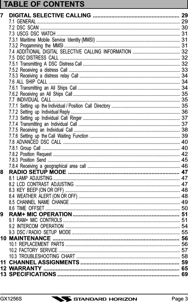
![GX1256SPage 508.6 TIME OFFSETSets the time difference between local time and UTC (Universal Time Coor-dinated or GMT Greenwich Mean Time). Time is displayed if the QUEST+ isconnected to a GPS receiver.1. Press and hold down the [CALL/SET(MENU)] key until“RADIO SETUP” appears.2. Press the [CALL/SET(MENU)] key, then press the[DOWN] key to select “TIME.”3. Press the [CALL/SET(MENU)] key to enable adjustingthis item (The number in the display will flash).4. Press the [UP] or [DOWN] key to select “Time Offset”from UTC. Be sure that when selecting the offset thatthe display shows “TIME –” for negative offset, or“TIME +” for a positive offset. Refer to Offset Time Table.See illustration below to find your offset time from UTC.If 0:0 is assigned, the time is the same as UTC.6. Press the [CALL/SET(MENU)] key to store the time off-set.7. Press the [DOWN] key to select “EXIT,” then press the[CALL/SET(MENU)] key.8. Press the [DOWN] key to select “EXIT,” then press the [CALL/SET(MENU)] key to return to the normal operation.NOTEDuring Daylight Saving time subtract 1 hour from the offset shown aboveand enter this offset in step 4 above.OFFSET TIME TABLE](https://usermanual.wiki/Yaesu-Musen/30053X30/User-Guide-421472-Page-50.png)
![GX1256S Page 519 RAM+ MIC OPERATIONIf the enhanced optional RAM+ Mic (CMP25) is connected to the remotemicrophone connector on the transceiver’s rear panel, the transceiver canuse the remote control operation except for a few functions. The RAM+ Micsupplied with 23 feet (7 m) of routing cable and can be extended up to 70feet (21 m) using three 23 feet extension cables model CT-100. The inter-com operation can be used between the RAM+ Mic and the transceiver.9.1 RAM+ MIC CONTROLSSQUELCH CONTROL (SQL)Activates the squelch adjusting mode.Press this key to activate the squelch adjusting mode. Press themicrophone’s [] or [] key to adjust the squelch.When [] key is pressed and held down for 1 second or more, the squelchis turned off.SCAN DWNAVWXCALLSETMEM ICU.I.CMENU169](https://usermanual.wiki/Yaesu-Musen/30053X30/User-Guide-421472-Page-51.png)
![GX1256SPage 52VOLUME KEY (VOL)Activates the volume adjusting mode.Press this key to activate the volume adjusting mode. Press themicrophone’s [] or [] to adjust the volume.POWER SWITCH (PWR)Press and hold down this key to turn to the transceiver and RAM+ Mic onand off.PTT (Push-To-Talk) SWITCHActivates transmission.[H/L] KEYToggles between high and low power. When the [H/L] key is pressedwhile the transceiver is on channel 13 or 67, the power will temporarilyswitch from LO to HI power until the PTT is released. The [H/L] key doesnot function on transmit inhibited and low power only channels.[](UP)/[](DOWN) KEYThese keys are used to select channels, adjusts the volume and squelchlevel, and to choose the item selection of different functions (such as theDSC operation). In many ways, these keys emulate the function of thetransceiver’s CHANNEL selector knob.[16/9] KEYImmediately recalls channel 16 from any channel location. Holding downthis key recalls channel 9. Pressing the [16/9] key reverts to the previousselected working channel.Secondary usePlease see secondary use for the [WX] and [MEM] key.KEY PAD[SCAN] Key1. Starts and stops scanning of programmed channels.2. If held while the [UP()] or [DOWN()] key on the microphone arepressed, the radio will show the channels programmed in scanmemory. This function will not work if the unit is scanning.NOTE: The priority channel is channel 16 only.](https://usermanual.wiki/Yaesu-Musen/30053X30/User-Guide-421472-Page-52.png)
![GX1256S Page 53[CALL/SET] KeyThe [CALL/SET] key functions as the enter key.Secondary usePress the [CALL/SET] key to access the DSC OPERATION menu.Press and hold the [CALL/SET] key to access the SETUP menu.[DW] KeyWatches for a transmission on CH16 and another selected channel untileither signal is received. (Dual watch)NOTE: When the DSC SCANNING feature is enabled (see section 7.15DSC SCAN), the radio watches for a transmission on CH16, anotherselected channel, and CH70 until either signal is received (Triple watch).Secondary usePress and hold [DW] key, intercom operation will operate between radioand RAM Mic.[NAV] KeyPress and hold this key, when connected to the GPS receiver, the LCDdisplays Position Data from the GPS.[WX] KeyImmediately recalls the previously selected NOAA weather channel fromany channel location.Secondary useHolding down the [16/9] key while pressing the [WX] key changes themode from USA to International or Canadian.NOTE: If position is displayed, this icon will be hidden.[DISTRESS] KEYUsed to send a DSC Distress Call. To send the distress call:1. Lift the red rubber cover.2. Press and hold the Red button. The RAM+ display willcount down (3-2-1) and then transmit the Distress call.3. When the distress signal is sent, Ch70 and “TX” iconwill appear on the LCD. After the message has beensent, the radio will sound a Distress Alarm.4. The transceiver “shadow-watches” for a transmissionon CH16 or CH70 until an acknowledgment signal isreceived. “DISTRESS” and “WAITING” will appear onthe LCD.](https://usermanual.wiki/Yaesu-Musen/30053X30/User-Guide-421472-Page-53.png)
![GX1256SPage 545. If an acknowledgement is received, select channel 16and advise your distress situation.6. If no acknowledgment is received, the distress call isrepeated in 4 minute intervals until an acknowledg-ment is received.7. When a DSC Distress acknowledgment is received, a distress alarmsounds and channel 16 is automatically selected. The LCD showsthe MMSI of the ship responding to your distress.RECEIVED ACK: acknowledgment signal is received.RECEIVED RLY: relay signal is received from another vessel or coaststation.8. To cancel the DSC distress alarm signal from the speaker, press anykey.9.2 INTERCOM OPERATION9.2.1 Communication1. Press and hold the [DW] key while in the “RADIO” mode, the mode ischanged to “INTERCOM” mode. If the [DW] key pressed and held againthe QUEST+ will revert to “RADIO” mode.2. When the “INTERCOM” operation is activated, “IC” is dis-played on the LCD.3. Press the PTT switch. The “TALK” is displayed.NOTE: A warning beep is emitted when the RAM+ MicPTT switch is pressed while the transceiver microphone’sPTT switch is pressed.4. Speak slowly and clearly into the microphone, hold themicrophone about 1/2 inch away from your mouth.5. When finished, release the PTT switch.9.2.2 CallingHold down the [DW] key for 1 second or more, when the “INTERCOM” op-eration is activated. A calling beep is emitted twice from the transceiverspeaker.](https://usermanual.wiki/Yaesu-Musen/30053X30/User-Guide-421472-Page-54.png)
![GX1256S Page 559.3 DSC/RADIO SETUP MODEThe CMP25 can access the DSC / RADIO setup menu (refer to section 7“DIGITAL SELECTIVE CALLING” and section 8 “RADIO SETUP MODE” fordetails). However, the LAMP, CONTRAST, and KEY BEEP menu item whichis accessed from the CMP25 only controls the CMP25’s display and speaker.DSC/RADIO Setup mode from the CMP25:1. Press and hold down the [CALL/SET] key until “RADIO SETUP” menuappears.2. Press the []/[] key to select “RADIO SET” or “DSC SETUP” menu.3. Press the [CALL/SET] key, then select the menu item you wish to workon by pressing the []/[] key.4. Press the [CALL/SET] key.5. Press the []/[] key to change the value or condition for the menuitem, then press the [CALL/SET] key to save the new setting.6. Press the []/[] key to select “EXIT,” then press the [CALL/SET] keyto return to the normal operation.RADIO SETUP-menu DSC SETUP-menu](https://usermanual.wiki/Yaesu-Musen/30053X30/User-Guide-421472-Page-55.png)