Yaesu Musen 30193X20 Marine Transceiver User Manual
Yaesu Musen Co., Ltd. Marine Transceiver
UserManual.wiki
>
Yaesu Musen
>
30193X20 User Manual
operating manual
Navigation menu
Upload a User Manual
Namespaces
Wiki Guide
HTML
PDF
Info
Views
User Manual
Discussion / Help
Navigation
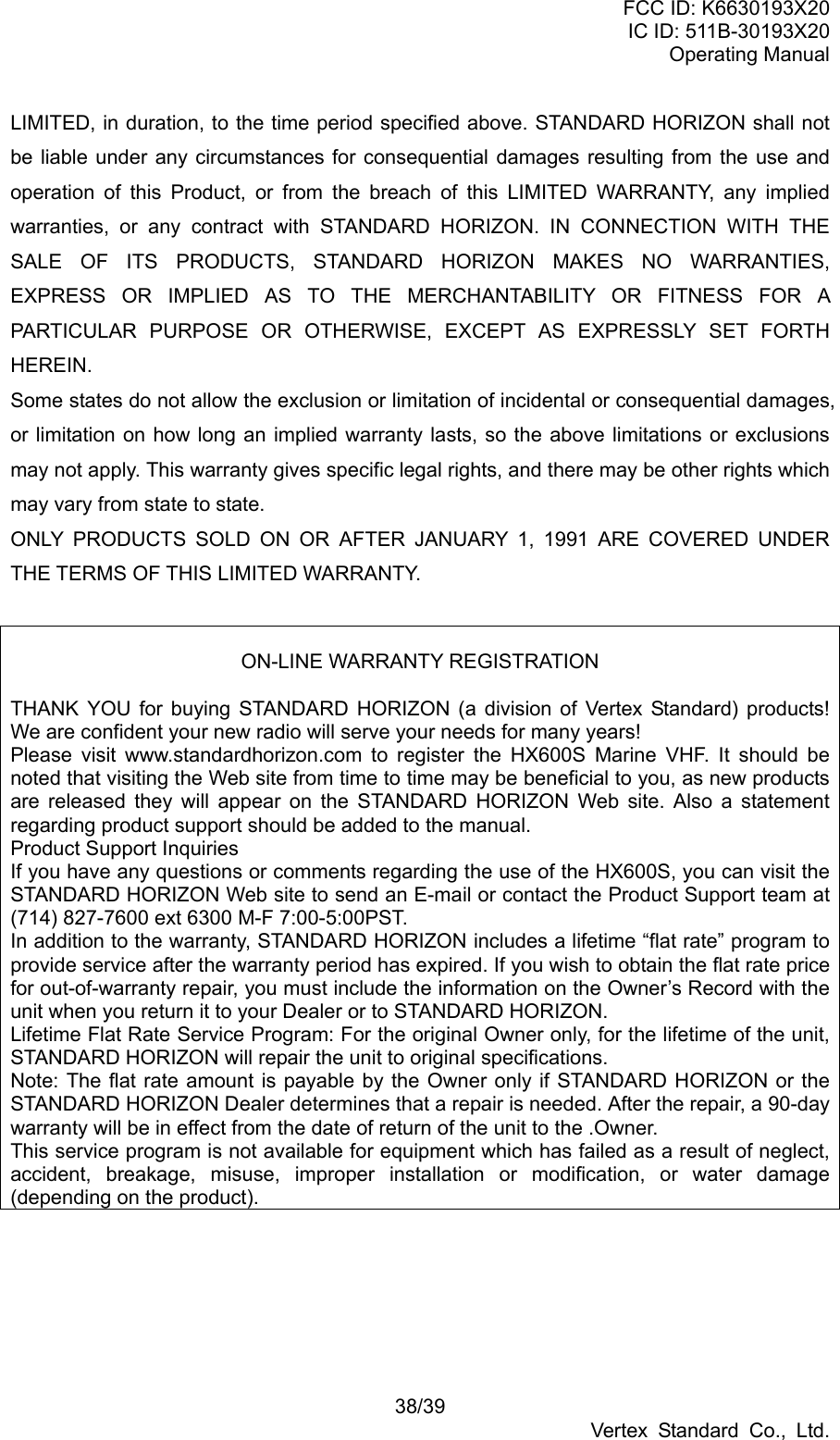
![FCC ID: K6630193X20 IC ID: 511B-30193X20 Operating Manual 5/39 Vertex Standard Co., Ltd. 1. GENERAL INFORMATION 1.1 INTRODUCTION The HX600S is a SUBMERSIBLE miniature 5-Watt portable two way marine transceiver. The transceiver has all allocated USA, International, or Canadian channels. It has emergency channel 16 which can be immediately selected from any channel by pressing the [16/9] key. NOAA Weather channels can also be accessed immediately by pressing the [WX] key. In addition to these functions the HX600S can transmit a Digital Selective Distress Call with Latitude/Longitude when a GPS is connected to the CD-33 Cradle Charger. Besides VHF marine transceiver operation, the HX600S provides FM / AM broadcast bands, and AM aircraft bands. The HX600S includes the following features: Memory Scanning, Priority Scanning, NOAA Weather Alert, Battery Saver, easy-to-read large LCD display, EEPROM memory back-up, Battery Life displayed on LCD, and a transmit Time-Out Timer (TOT). In the marine band, the transmitter provides a maximum of 5 Watts output, and has the selection of 2.5 Watts and 1 Watt to assist the user in ensuring maximum battery life. The optional FVP-31 Voice Scrambler can be installed to permit secure voice communications with other Standard Horizon radios with the FVP-31 or CVS2500 scramblers installed. 2. ACCESSORIES 2.1 PACKING LIST When the package containing the transceiver is first opened, please check it for the following contents: HX600S Transceiver FNB-83 7.2 V, 1400 mAh Ni-MH Battery Pack CD-33 Charger Cradle for HX600S NC-88B 120VAC Wall Charger for CD-33 E-DC-19A DC Cable with 12 V Cigarette Lighter Plug for CD-33 Belt Clip Lanyard Owner’s Manual 2.2 OPTIONS 1 CMP460 Noise-canceling Waterproof Speaker/Microphone 2 MH-57A4B Mini Speaker/Microphone](https://usermanual.wiki/Yaesu-Musen/30193X20/User-Guide-602131-Page-5.png)
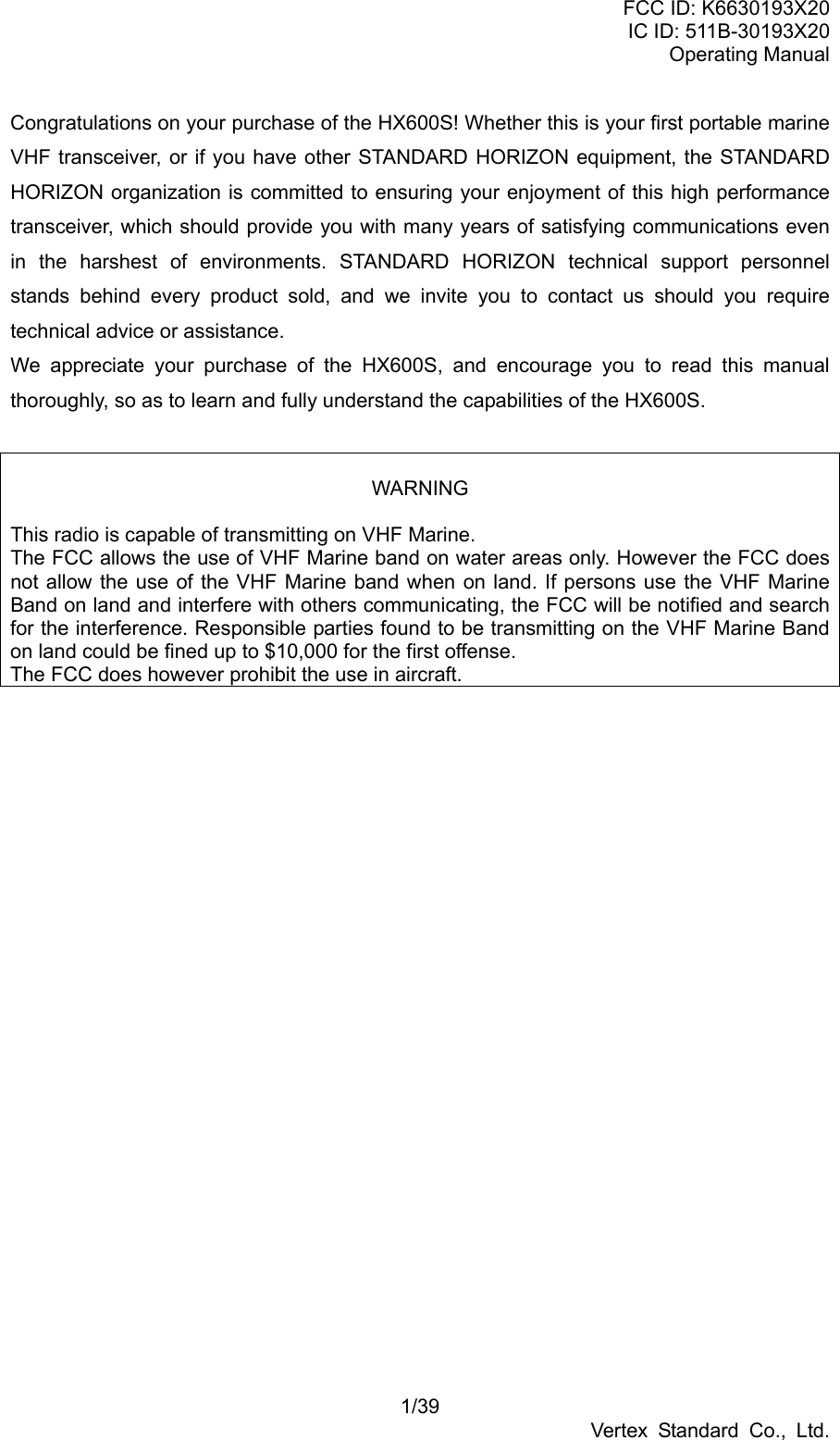
![FCC ID: K6630193X20 IC ID: 511B-30193X20 Operating Manual 11/39 Vertex Standard Co., Ltd. MIC/SP JACK The jack accepts the optional CMP460 Speaker/Microphone, MH-57A4B Mini Speaker/Microphone, or VC-24 VOX Headset. When this jack is used, the internal speaker is disabled. PUSH-TO-TALK (PTT) SWITCH When pushed activates the transmitter of the selected band. [BAND] KEY Press to select the VHF Marine, FM Broadcast, AM Broadcast, and AIR (aircraft) bands. [16/9] KEY Immediately recalls channel 16 from any marine channel or band location. Holding down this key recalls channel 9. [WX] KEY Immediately recalls the last-used NOAA Weather Channel from any channel location. Recalls the previously- selected working channel when the [WX] key is pressed again. Secondary use: When the [16/9] key is held and the [WX] key is pressed, the radio will change the marine channel between the USA, International, and Canadian channels. [(UP)] KEY Press to select a desired channel. Each press increases the channel number. When held down, the channels increase continuously. [(DOWN)] KEY Press to select a desired channel. Each press decreases the channel number. When held down, the channels decrease continuously. NMEA TERMINAL Connect to GPS receiver that outputs NMEA sentences GLL, GGA, GNS, and RMC via the CD-33 Charger Cradle. Keep these terminals clean. [SCAN] KEY](https://usermanual.wiki/Yaesu-Musen/30193X20/User-Guide-602131-Page-11.png)
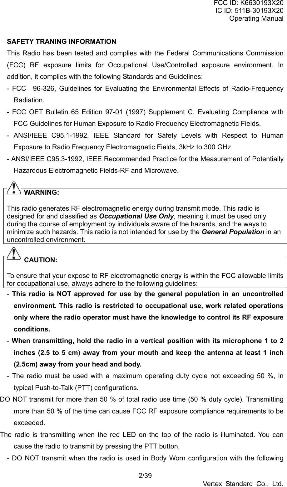
![FCC ID: K6630193X20 IC ID: 511B-30193X20 Operating Manual 12/39 Vertex Standard Co., Ltd. Starts scanning and priority scanning of programmed channels. When scanning, press and hold this key to turn on and off priority scan (P is shown on the left side of the display during Priority scanning). [PRESET] KEY Immediately recalls one of up to 10 user preset memories for each band (shown as P0-P9 on the LCD). Pressing this key repeatedly scrolls through the preset memory channels. [H/L] KEY On the Marine Band, changes the transmitter output power between High (5 Watts), Medium (2.5 Watts), and Low (1 Watt). Does not operate on “Low power only,” Marine “transmission inhibit.” [MEM] KEY Press this key to memorize the selected channel for scanning. When pressed a “MEM” icon will be shown on the LCD display indicating the channel has been saved to scan memory. The scan memory is only used with the Marine and WX channels. To delete the channel from scan memory, select the channel and press this key until “MEM” is removed from the display. BUSY/TX INDICATOR This indicator illuminates different colors depending on the band that is selected. The chart to the right shows the colors illuminated with the Squelch open or a signal is received. This indicator glows red during transmit. BAND COLOR MARINE Blue AM/FM/AIR Marine Blue [DISTRESS] KEY When radio is programmed with a MMSI and this key is pressed once and pressed and held again for 3 seconds the radio will transmit a DSC Distress Call. To send the distress call, see section 7.9 “DIGITAL SELECTIVE CALLING.” 6. BASIC OPERATION 6.1 INITIAL SETUP](https://usermanual.wiki/Yaesu-Musen/30193X20/User-Guide-602131-Page-12.png)
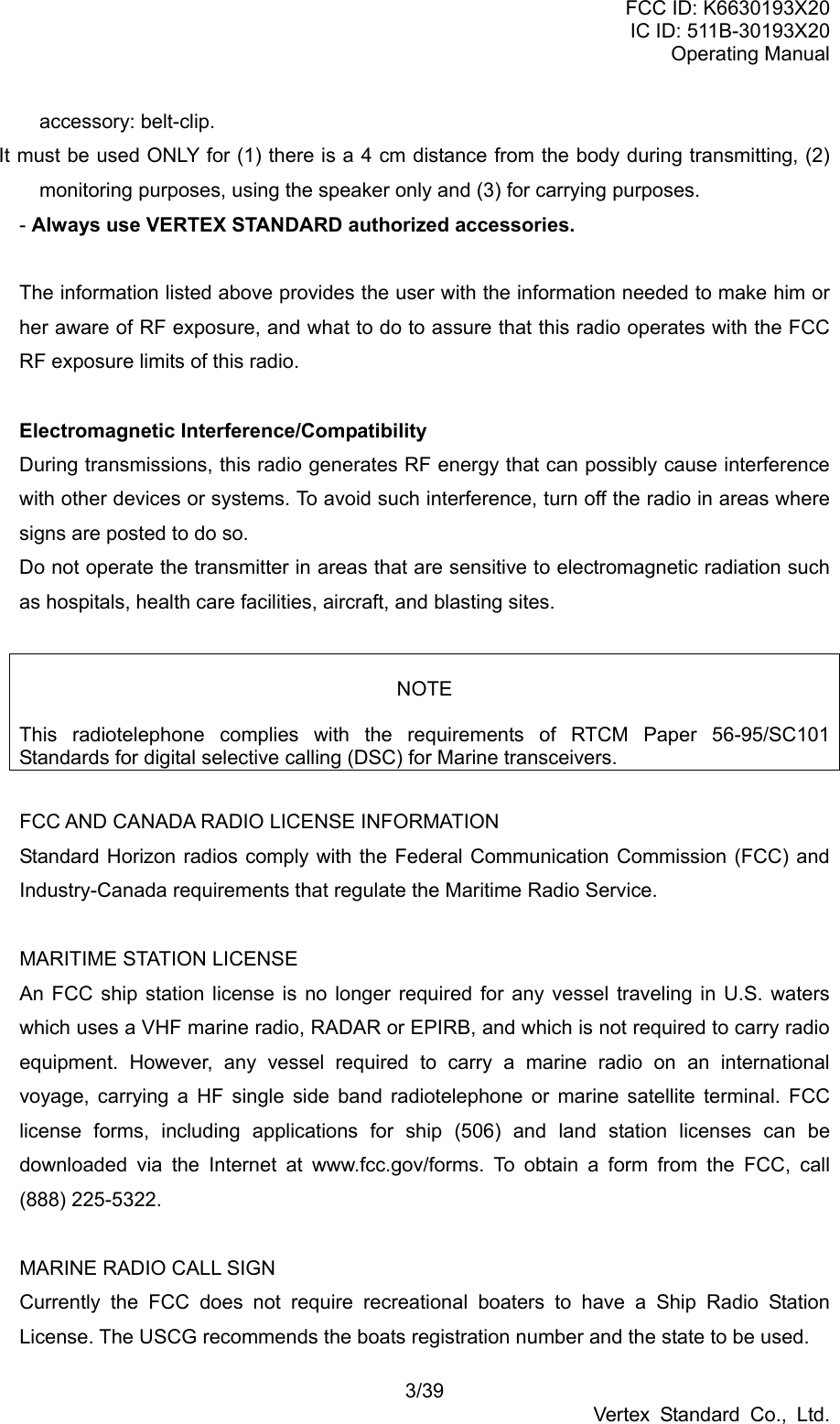
![FCC ID: K6630193X20 IC ID: 511B-30193X20 Operating Manual 13/39 Vertex Standard Co., Ltd. 1. Install the belt clip on the transceiver according to the description in the box below, if desired. 2. Install the nylon carrying strap on the belt clip, if desired. 3. Install the battery pack on the transceiver (see section 4.1.3 “BATTERY INSTALLATION/REMOVAL”). NOTE: Water resistance of the transceiver is assured only when the battery pack is attached to the transceiver and MIC/SP rubber cap is installed in the MIC/SP jack. 6.2 RECEPTION 1. Press and hold the POWER SWITCH to turn the transceiver on. 2. Turn up the VOLUME CONTROL knob until the noise or audio from the speaker is at a comfortable level. 3. Select the desired operating band among the VHF Marine band, FM band, AM band, and AIR band by pressing the [BAND] key repetitively to switch between the bands. 4. Press the [] or [] key to select a channel or frequency that has no signal being received (no one is transmitting on the channel) 5. Press the [SCAN] key momentarily; the HX600S will begin scanning toward a higher channel or frequency and will stop when it receives a signal strong enough to break through the squelch threshold. Press the [SCAN] key momentarily to channel the scanning. Refer to section 7.2 for programming channels into scan memory. 6. Please refer to section 16 for VHF Marine 6.3 TRANSMISSION 1. Perform steps 1 through 7 of the RECEPTION discussion above. 2. Before transmitting, monitor the channel and make sure it is clear. THIS IS AN FCC REQUIREMENT! 3. For communications over short distances on the Marine band, press the [H/L] key until “L” is displayed on the LCD. This indicates Low power (approximately 1 watt). Note Transmitting on 1 watt prolongs battery life. Low power (1 watt) should be selected whenever possible. 4. If using Low power is not effective, select Medium power (2.5 watts) or High power (5 watts) by pressing the [H/L] key until “M” (Medium power) or “H” (High power) is displayed. 5. When receiving a signal, wait until the incoming signal stops before transmitting. The](https://usermanual.wiki/Yaesu-Musen/30193X20/User-Guide-602131-Page-13.png)
![FCC ID: K6630193X20 IC ID: 511B-30193X20 Operating Manual 14/39 Vertex Standard Co., Ltd. transceiver cannot transmit and receive simultaneously. 6. Press the PTT (Push-To-Talk) switch to transmit. The “TX” indicator is displayed during transmission. 7. Speak slowly and clearly into the microphone. Hold the microphone about 1/2 to 1 inch away from your mouth. 8. When the transmission is finished, release the PTT switch. For an overview of VHF Marine band operating procedures refer to section 3. 6.3.1 TRANSMIT TIME - OUT TIMER (TOT) While the PTT switch is held down, transmission time is limited to 5 minutes. This prevents prolonged (unintentional) transmissions. About 10 seconds before automatic transmitter shutdown, a warning beep sounds from the speaker. The transceiver automatically switches to the receiving mode, even if the PTT switch is held down. Before transmitting again, the PTT switch must first be released, and then pressed again. This Time-Out-Timer (TOT) prevents a continuous transmission that would result from an accidentally stuck PTT switch. 6.4 NOAA WEATHER CHANNELS 1. To receive a NOAA weather broadcast, press the [WX] key. The transceiver changes to the weather channel mode. This mode consists of a special preset memory bank containing the NOAA weather channels. 2. The transceiver will be set to the last used NOAA weather channel. Press the [] or [] key to change to other weather channels. 3. To exit from the weather channel mode, press the [WX] key. The transceiver will revert to the channel you were using prior to switching to the weather channel mode. 6.4.1 NOAA WEATHER ALERT In the event of extreme weather disturbances such as storms and hurricanes, NOAA (National Oceanic and Atmospheric Administration) sends a “weather alert” consisting of a 1050 Hz tone, followed by weather reports on the weather channels. The transceiver is capable of receiving this alert if the following is performed: 1. Program your area’s weather channels into the transceiver’s scan memory. Follow the same procedure as for regular channels. 2. Press the [SCAN] key to start the scan. 3. The memorized weather channels are scanned along with the regular memorized channels. Scanning will not stop on the (continuous) weather broadcast channels](https://usermanual.wiki/Yaesu-Musen/30193X20/User-Guide-602131-Page-14.png)
![FCC ID: K6630193X20 IC ID: 511B-30193X20 Operating Manual 15/39 Vertex Standard Co., Ltd. unless the weather alert tone is received. 4. When an alert is received on a weather channel, scanning stops and the transceiver emits a beeping tone that will stay on for 5 minutes. 5. Press the [WX] key to listen to the Weather Alert. 6.5 PRESET CHANNELS (P0 ~ P9): INSTANT ACCESS Ten user assigned channels can be programmed for instant access. Pressing the [PRESET] key activates the user assigned channel bank. If the [PRESET] key is pressed and no channels have been assigned, an alert beep will be emitted twice from the speaker. The HX600S provides the ten Preset channel for each individual operating band (VHF Marine, AM Broadcast, FM Broadcast and Air Band). Programming 1. Select the desired band by pressing the [BAND] key. 2. Hold down the [PRESET] key, and press the [] or [] key (repeatedly, if necessary) until the desired channel number or frequency is displayed. 3. With the desired number displayed, release the [PRESET] key. 4. Repeat steps 2 and 3 to program the desired channels into Preset Channels “P1” ~ “P9.” 5. To delete a Preset Channel, hold down the [PRESET] key and press the [] or [] key until the Preset Channel number to be deleted is displayed, then release the [PRESET] key. You may add an alpha-numeric name “Tag” to any desired Preset Channel; refer to CH NAME SET item on the section 13 “MENU (“SET”) MODE.” Operation Pressing the [PRESET] key will toggle between Preset Channels “P0” - “P9” and the last selected “regular” channel. Preset Channel “P0” is represented by “P0” to the left of the channel number on the LCD, and preset channel “P1” is represented by “P1” and so forth. Press the [SCAN] key while on any of the Preset Channels, the HX600S will begin scanning the Preset Channels of the selected band. 6.6 ENABLING S.O.S STROBE OPERATION The S.O.S. STROBE feature utilizes the high-intensity strobe LED on the front of the HX600S as a visual distress beacon. When enabled, the LED blinks the internationally-recognized Morse Code “S.O.S.” message (...---...) at a rate of 5 words per](https://usermanual.wiki/Yaesu-Musen/30193X20/User-Guide-602131-Page-15.png)
![FCC ID: K6630193X20 IC ID: 511B-30193X20 Operating Manual 16/39 Vertex Standard Co., Ltd. minute. This can be very useful in summoning help from rescuers who may not be able to communicate with you via radio. 1. Hold down the [MEM] key while turning the radio on to activate the emergency S.O.S. Strobe. Once the radio comes on, the BUSY/TX LED will flash the Morse Code S.O.S. message repeatedly. 2. The S.O.S. strobe function is interrupted when a signal is received or if the squelch control is turned so audio is heard from the speaker. and during transmission. 3. To disable the S.O.S. strobe function, turn the radio off and back on again. 7. ADVANCED OPERATION ON THE MARINE BAND 7.1 USA, CANADIAN, AND INTERNATIONAL CHANNELS 1. To change from US to Canadian or International Marine Channels, hold down the [16/9] key and press the [WX] key. The band will change from USA, to International, and to Canadian with each press. 2. “USA” appears on the LCD for the USA band, “CAN” appears for the Canadian band, and “INTL” appears for the International band. 3. Refer to the marine channel charts in section 16 “VHF MARINE CHANNEL ASSIGNMENTS” for allocated channels. 7.2 MEMORY SCAN The HX600S can be programmed to scan channels from a minimum of 2 channels up to all channels in the marine band. If an incoming signal is detected on one of the channels during scan, the radio will pause on that channel, allowing you to listen to the incoming transmission. 1. Select the desired channel to be included in the scan memory using the [] or [] key. 2. Press the [MEM] key to store the channel into the transceiver’s scan memory. “MEM” will be displayed on the LCD. 3. Repeat steps 1 and 2 for all the channels to be scanned. 4. To delete a channel from the transceiver’s scan memory, select the memorized channel. Press the [MEM] key until “MEM” is removed from the display. 5. All channels programmed remain in the transceiver’s scan memory even if the power is turned off. See section 11 “RESETTING THE TRANSCEIVER’S MICROPROCESSOR” to clear all channels from the transceiver’s scan memory. 6. Adjust the SQUELCH CONTROL knob until background noise is eliminated. 7. To start scanning, press the [SCAN] key. The scan proceeds from the lowest to the highest programmed channel and stops scanning when a transmission is received.](https://usermanual.wiki/Yaesu-Musen/30193X20/User-Guide-602131-Page-16.png)
![FCC ID: K6630193X20 IC ID: 511B-30193X20 Operating Manual 17/39 Vertex Standard Co., Ltd. Scanning will resume when the incoming signal disappears at the end of the transmission. A small “SCAN” icon is shown on the center bottom of the display during scanning. 8. To stop the scan, press the [SCAN] key. 7.3 PRIORITY SCAN The priority scanning feature allows the radio to scan while also keeping watch on a particularly important “priority channel.” The following channels can be set as the priority channel: 16, 09, and MARINE Preset Channel. 1. To set the priority channel, hold down the [16/9] key and press the [MEM] key. The channel will change from 16 to 09 to Preset Channels P0 through P9 with each press of the [MEM] key. When the [16/9] key is released the displayed channel will be set as the priority channel (the large “P” icon will appear at the right side of the channel number). 2. For priority scanning, hold down the [SCAN] key during normal scanning. Scanning will proceed between the memorized channels and the priority channel. The priority channel will be scanned after each programmed channel. A small “PSCN” is shown on the center bottom of the display during priority scanning. 3. As an example of priority scanning, let us say that marine channels 06, 07, and 08 are memorized in the transceiver’s scan memory. Priority scanning will proceed in the following sequence: [CH06] ---> [Priority Channel] ---> [CH07] ---> [Priority Channel] ---> [CH08] ---> [Priority Channel] ---> [CH06] ---> [Priority Channel].......... 4. Even when the transceiver stops and listens to the signal of a programmed channel, the transceiver will shift to a “dual watch” mode between this channel and the priority channel. Therefore, your priority watching of the designated channel is not compromised when the scanner has paused on an active channel. 5. Hold down the [SCAN] key to change the priority scanning to normal scanning, and then press the [SCAN] key to stop the scan and return to normal operation. 7.5 EMERGENCY CHANNEL 16 1. To select the emergency channel, press the [16/9] key from any channel. 2. If you cannot contact anyone on channel 16, switch to another channel. 3. See section 10.1 “EMERGENCY (CHANNEL 16 USE)” for additional emergency operating practices. 4. To recall the previously-used channel when you are finished on channel 16, press the](https://usermanual.wiki/Yaesu-Musen/30193X20/User-Guide-602131-Page-17.png)
![FCC ID: K6630193X20 IC ID: 511B-30193X20 Operating Manual 18/39 Vertex Standard Co., Ltd. [16/9] key again. 7.6 CHANNEL 9 Channel 9 is used as a hailing channel for initial, non-emergency contacts with other vessels. Hold down the [16/9] key for 1 second to select channel 9. You should change to a working channel, after contact is established (so as to keep the hailing channel clear for other users). 7.7 OPERATING ON USA OR CANADIAN 13, OR USA CHANNEL 67 USA and Canadian Channel 13, USA 67 are used at docks, bridges and for maneuvering in port. Messages on this channel must concern navigation only, such as meeting and passing in restricted waters. In emergencies and when approaching blind river bends, high power is allowed. Holding down the [H/L] key will change the power output from 1 Watt (L) to 5 Watts (H); if pressed and held again 2.5 Watts (M) will be selected. When the PTT switch is released, the transceiver will revert to low power. Press and hold in the [H/L] key again if you need High power on a subsequent transmission. 7.8 OPERATING ON USA CHANNEL 67 USA Channel 67 is used for navigational bridge-to-bridge traffic between ships. This channel has been allocated for temporary high power transmission if communication is not able to be established on one watt. Select Channel 67, then press the [H/L] key to set the transmitter output to either High or Medium power. When the PTT switch is released, the transceiver will revert to low power. 7.9 DIGITAL SELECTIVE CALLING 7.9.1 GENERAL 7.9.1.1 Digital Selective Calling (DSC) Digital Selective Calling is a semi-automated method of establishing a radio call; it has been designated by the International Maritime Organization (IMO) as an international standard for establishing VHF, MF and HF radio calls. It had also been designated as part of the Global Maritime Distress and Safety System (GMDSS). It is planned that DSC will eventually replace aural watches on distress frequencies and will be used to announce routine and urgent maritime safety information broadcasts. The HX600S has a DSC Distress feature that allows mariners to instantly transmit a VHF Marine distress call with GPS position (when connected to the transceiver) to the US Coast Guard and other vessels within range of the transmission.](https://usermanual.wiki/Yaesu-Musen/30193X20/User-Guide-602131-Page-18.png)
![FCC ID: K6630193X20 IC ID: 511B-30193X20 Operating Manual 19/39 Vertex Standard Co., Ltd. 7.9.1.2 Maritime Mobile Service Identity (MMSI) What is an MMSI? An MMSI is a nine digit number used on Marine Transceivers capable of using Digital Selective Calling (DSC). This number is used by the HX600S when a Marine DSC Distress call is transmitted. This number is registered with the USCG. Refer to section 13 “MENU (“SET”) MODE” (MMSI REG). NOTE: An MMSI must be programmed into the HX600S before the DSC Distress function will operate. If you have a fixed mounted DSC VHF and already have a MMSI, this MMSI should be programmed into the HX600S. How can I obtain a MMSI assignment? Currently there are two companies that offer MMSI numbers: Boat US at (800) 563-1539 or visit the web site http://www.boatus.com/mmsi/. Seatow at (631) 765-3660 or visit the web site http://www.seatow.com/mmsiinfo.htm WARNING: This radio is designed to generate a digital maritime distress and safety call to facilitate search and rescue. To be effective as a safety device, this equipment must be used only within communication range of a shore-based VHF marine channel 70 distress and safety watch system. 7.9.2 SENDING A DISTRESS CALL The distress call automatically includes the vessel’s DSC MMSI and Lat/Lon position. The vessel’s position will only be transmitted if the transceiver is properly connected to an operating GPS receiver with NMEA output. 1. Lift the red DISTRESS rubber cover on the right side of the transceiver and press the [DISTRESS] key. “DSC DISTRESS” will appear on the top of the LCD. 2. Press and hold in the [DISTRESS] key for 3 seconds. The LCD will count down (3s, 2s, 1s), and afterwards the HX600S will transmit the DSC Distress Call on channel 70. 3. When the distress signal is being sent, “TX” icon will appear on the LCD. After the message has been sent, the Distress Alarm will sound. 4. The transceiver “shadow-watches” for a transmission between CH16 and CH70 until an acknowledgment signal is received. 5. If no acknowledgment is received, the distress call is repeated in three minute intervals until an acknowledgment is received. 6. To cancel the distress call alarm, press the [16/9] key. 7. To send the CANCEL call:](https://usermanual.wiki/Yaesu-Musen/30193X20/User-Guide-602131-Page-19.png)
![FCC ID: K6630193X20 IC ID: 511B-30193X20 Operating Manual 20/39 Vertex Standard Co., Ltd. Press the [DISTRESS] key, then press the [] or [] key until “CANCEL” is shown on the LCD. Press the [DISTRESS] key. NOTE: When a GPS receiver with NMEA output is connected via the CD-26 Charger Cradle, the vessel’s position is automatically transmitted with the distress call. The HX600S will remember the position input from the GPS until the radio is turned off. 7.10 SIMPLEX/DUPLEX CHANNEL USE All Marine channels are factory-programmed in accordance with FCC (USA), Industry Canada and International regulations. The mode of operation cannot be altered from simplex to duplex or vice-versa. Simplex (ship to ship) or duplex (marine operator) mode is automatically activated, depending on the channel and whether the USA, International or Canadian operating band is selected. 9. SCRAMABLER OPERATION 9.1 VOICE SCRAMBLER UNIT The optional FVP-31 Voice Scrambler Unit permits secure voice communications with stations within your network, which prevents others from listening using normal communication equipment. To activate the Voice Scrambler: 1. Select the channel on which you wish to activate the Voice Scrambler. 2. Press the [MENU] key to enter the Menu Mode. 3. Press the [] or [] key to select the Menu item (SCRAMBLER). 4. Press the [MENU] key to enable adjustment of this Menu item. 5. Press the [] or [] key to set this Menu item to “ON.” 6. When you have completed your selection, press the [MENU] key to save the new setting, and then press the PTT key to exit to normal operation. 7. To disable the Voice Scrambler, select “OFF” in step 5 above. Note: Voice Scrambler may not be activated on Marine Channels 16 and 70. 10. OPERATING PRACTICES 10.1 EMERGENCY (CHANNEL 16 USE) Channel 16 is known as the Hail and Distress Channel. An emergency may be defined as a threat to life or property. In such instances, be sure the transceiver is on and set to](https://usermanual.wiki/Yaesu-Musen/30193X20/User-Guide-602131-Page-20.png)
![FCC ID: K6630193X20 IC ID: 511B-30193X20 Operating Manual 22/39 Vertex Standard Co., Ltd. call and then “this is” followed by the name of your vessel and your Station License (Call Sign). When the other vessel returns your call, immediately request another channel by saying “go to,” the number of the other channel, and “over.” Then switch to the new channel. When the new channel is not busy, call the other vessel. After a transmission, say “over,” and release the microphone’s push-to-talk (PTT) switch. When all communication with the other vessel is completed, end the last transmission by stating your Call Sign and the word “out.” Note that it is not necessary to state your Call Sign with each transmission, only at the beginning and end of the contact. Remember to return to Channel 16 when not using another channel. Some radios automatically monitor Channel 16 even when set to other channels or when scanning. 10.3 OPERATING ON CHANNELS 13 AND 67 Channel 13 is used at docks and bridges and by vessels maneuvering in port. Messages on this channel must concern navigation only, such as meeting and passing in restricted waters. Channel 67 is used for navigational traffic between vessels. By regulation, power is normally limited to 1 Watt on these channels. Your radio is programmed to automatically reduce power to this limit on these channels. However, in certain situations it may be necessary to temporarily use a higher power. See page 20 ([H/L] key) for means to temporarily override the low-power limit on these two channels. 10.4 PROHIBITED COMMUNICATIONS The FCC prohibits the following communications: ・False distress or emergency messages: ・Messages to “any boat” except in emergencies and radio tests; ・Messages to or from a vessel on land; ・Transmission while on land; ・Obscene, indecent, or profane language (potential fine of $10,000). 10.5 NOAA WEATHER ALERT TESTING In the event of a major storm or other appreciable weather condition requiring vessels at sea (or other bodies of water) to be notified, the NOAA (National Oceanographic and Atmospheric Administration) broadcasts a 1050 Hz tone that some VHF radios, including your HX600S, can detect for “Weather Alarm” purposes (refer to section 6.4.1 “NOAA WEATHER ALERT” for a discussion of how to use this feature). The 1050 Hz tone, when detected, will produce a loud beep in the speaker of the HX600S, to signal that a Weather](https://usermanual.wiki/Yaesu-Musen/30193X20/User-Guide-602131-Page-22.png)
![FCC ID: K6630193X20 IC ID: 511B-30193X20 Operating Manual 23/39 Vertex Standard Co., Ltd. Alert Broadcast is being received. In order to test this system, NOAA broadcasts the 1050 Hz tone every Wednesday sometime between 11 AM and 1 PM local time. You may use this opportunity to test your HX600S periodically to confirm that the Weather Alert feature is working, or for training crew members on how to configure the HX600S to receive the NOAA Weather Alerts. 11. RESETTING THE TRANSCEIVER’S MICROPROCESSOR Resetting the microprocessor restores the initial, factory-supplied conditions in the transceiver. These are called the “default” conditions. To reset the microprocessor, first turn the transceiver off. Then, while pressing and holding in the [WX] and [SCAN] keys, turn the transceiver on. The default conditions are: ・No channel numbers are in scan memory. ・Channel 16 is the priority channel. ・Channel 16 will be selected when the transceiver is turned on. ・WX channel 01 will be recalled when the [WX] key is pressed. ・Preset Channels are unassigned. Note: The above procedure also resets the microprocessor. Perform this procedure if an operational problem occurs which cannot be solved by normal operating procedures. 12. MENU (“SET”) MODE The HX600S’s Menu Mode allows a number of the HX600S operating parameters to be custom-configured for your operating requirements. The Menu Mode is easy to activate and set, using the following procedure: 1. Hold down the [SQL] key and then turn on the transceiver, to enter the Menu Mode. 2. Press the [SQL] key to select the Menu item to be adjusted. 3. Press the [] or [] key to enable adjustment of the selected Menu item. The menu item will blink 4. Press the [SQL] key to select the status or value of the Menu item. 5. After completing your adjustment, press the PTT key to save the new setting and exit to normal operation. BEEP Function: Enable/Disable the Keypad beeper.](https://usermanual.wiki/Yaesu-Musen/30193X20/User-Guide-602131-Page-23.png)
![FCC ID: K6630193X20 IC ID: 511B-30193X20 Operating Manual 24/39 Vertex Standard Co., Ltd. Available Values: ON / OFF Default: ON CH NAME SET Function: Changes the channel name shown on the display. 1. Select the channel on which you wish to change the name before recalling this Menu item. 2. Press the [MENU] key to enter the Menu Mode. 3. Press the [] or [] key to select this Menu item (CH NAME SET). 4. Press the [MENU] key to enable adjustment of this Menu item. 5. Press the [] or [] key to select the first character (letter, number, or symbol) in the name you wish to change, then press the [MEM] key to move to the next character. 6. If you make a mistake, press the [H/L] key to move back, and then reselect the correct letter, number, or symbol. 7. Repeat step 5 as many times as necessary to complete the name tag (up to 10 characters). 8. After completing your adjustment, press the [MENU] key to save the new setting. 9. Press the PTT key to exit to normal operation. DISPLAY MODE Function: Selects the information to be displayed on the LCD Available Values: BARO*1 / GPS NAV info*2 / CH name / Time*2 / None Default: CH name *1 : Requires optional SU-1 *2 : Requires GPS receiver. DISTRESS RING Function: Selects how long the DSC Distress alarm will ring Available Values: 3 min / 5 times / 10 times / 15 times Default: 3 min DW DISPLAY Function: Selects the Dual Watch scanning display mode. Available Values: Normal / Special](https://usermanual.wiki/Yaesu-Musen/30193X20/User-Guide-602131-Page-24.png)
![FCC ID: K6630193X20 IC ID: 511B-30193X20 Operating Manual 27/39 Vertex Standard Co., Ltd. The inherent quality of the solid-state components in STANDARD HORIZON radios will provide many years of continuous use. Take the following precautions to prevent damage to the radio. Keep the microphone connected or the jack covered at all times to prevent corrosion of electrical contacts; Never key the transmitter unless an antenna or suitable dummy load is connected to the antenna receptacle. Ensure that the input voltage does not exceed the value specified in your Owner’s Manual. Use only STANDARD HORIZON-approved accessories and replacement parts. 14.2 REPLACEMENT PARTS Occasionally an owner needs a replacement parts. These can be ordered from our Parts Department by writing or calling: Marine Division of Vertex Standard US Headquarters 10900 Walker Street, Cypress, CA 90630, U.S.A. Telephone (714) 827-7600 Commonly requested parts, and their part numbers are listed below. ・VOLUME Knob: xxxxxxxxx ・CD-26 Charger Cradle: xxxxxxxxx ・MIC/SP Cover: xxxxxxxxx ・DISTRESS Cover: xxxxxxxxx 14.3 TROUBLESHOOTING CHART TROUBLESHOOTING CHART SYMPTOM PROBABLE CAUSE REMEDY No channels memorized. Use the MEM key to enter desired channels into the transceiver’s memory. The [SCAN] key does not start the scan. Squelch is not adjusted. Adjust the squelch to threshold or to the point where noise just disappears. Further adjustment of the squelch control may eliminate incoming signals. The USA/INTL/CAN modes do not function. Proper operation not followed. HOLD down the 16/9 key and press the WX key. Cannot change any function. Key Lock is on. Turn Key Lock off. Refer to section 5, 5 LAMP key.](https://usermanual.wiki/Yaesu-Musen/30193X20/User-Guide-602131-Page-27.png)
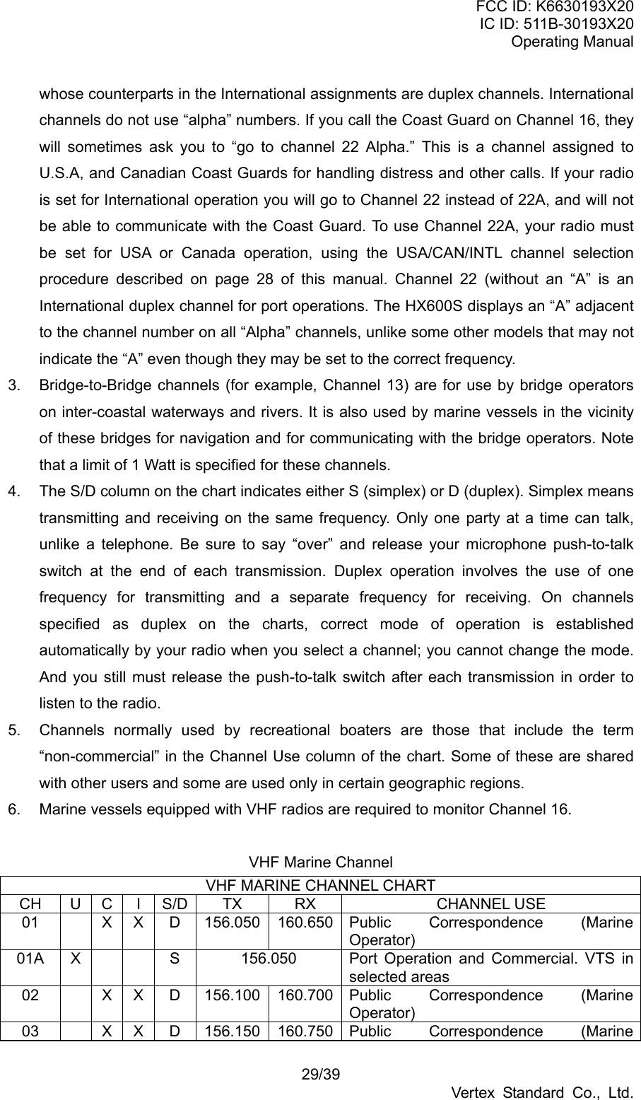
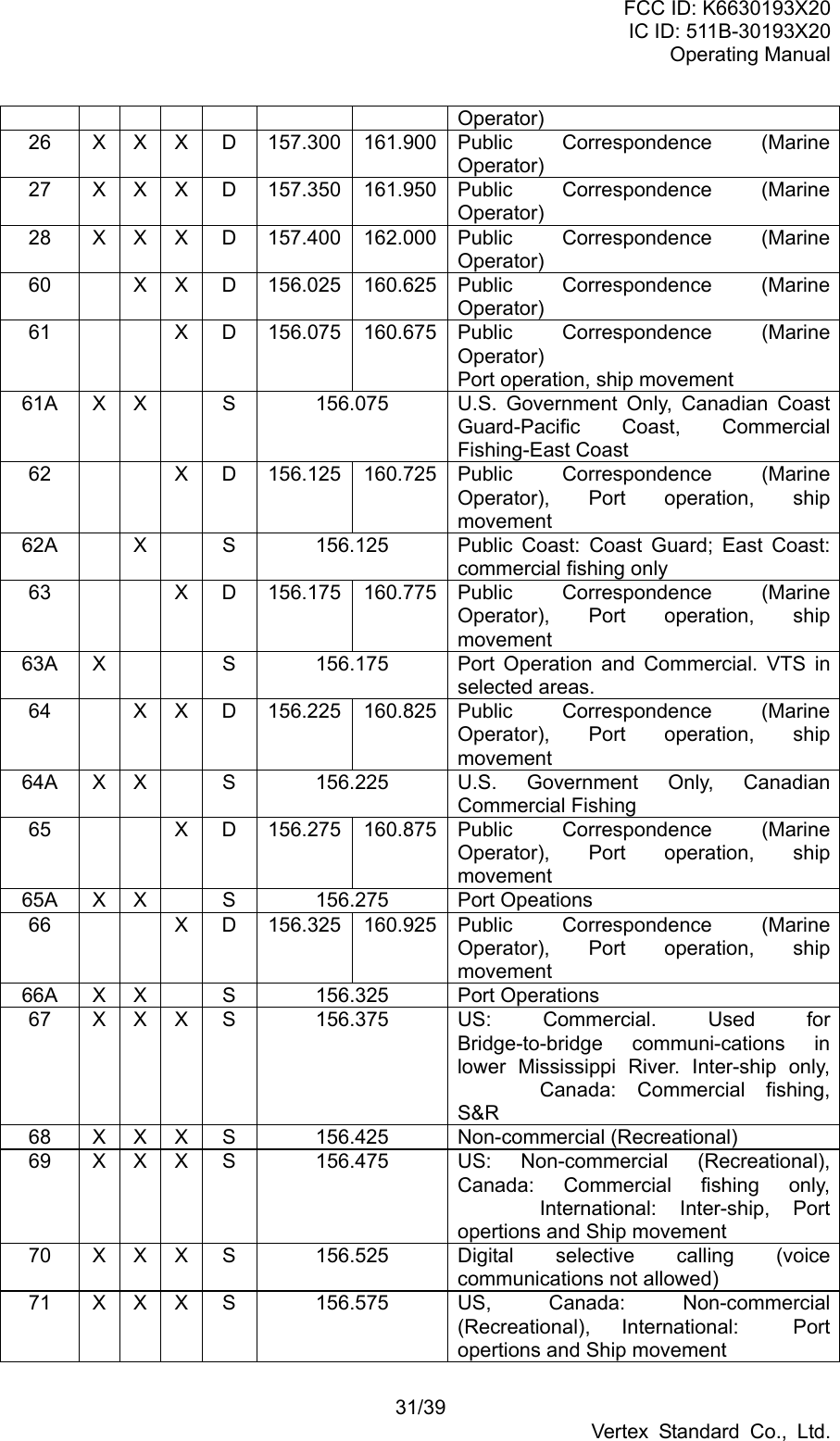
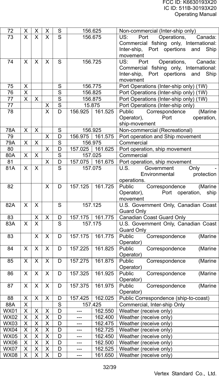
![FCC ID: K6630193X20 IC ID: 511B-30193X20 Operating Manual 28/39 Vertex Standard Co., Ltd. Key Lock does not function. Proper operation not followed. Hold down the LAMP key for 1 second. Indicator does not light when charging a battery. Defective battery FNB-83. Contact your Standard Horizon dealer. 15. INSTALLATIONS OF OPTION 15.1 FVP-31 VOICE SCRAMBLER UNIT 1. Make sure that the transceiver is off. Remove the hard or soft case, if used. Remove the battery pack. 2. Locate the connector for the optional unit under the caution seal in the battery compartment on the back of the radio; just peel off the caution seal. 3. Align the connector on the optional unit with the transceiver’s connector and gently press the unit into place. 4. Affix the new caution seal (supplied with the optional unit), and replace the battery. Installation is now complete. 15.2 FBA-25A BATTERY CASE FBA-25A is a battery case that holds six alkaline batteries and is used with the HX600S transceiver. Alkaline batteries can be used for transmission in an emergency, but power output is reduced to one watt, and battery life will be short. 1. Slide the batteries into the FBA-25A with the Negative [-] side of the batteries touching the spring connections inside the FBA-25A. 2. Insert the FBA-25A into the battery compartment on the back of the transceiver, then close the Battery Pack Latch until it locks in place with a “click.” Note: The battery indicator on the transceiver is only applicable to the FNB-83 rechargeable battery. Disregard this indication when using alkaline batteries. 16. VHF MARINE CHANNEL ASSIGNMENTS Tables on the following pages list the VHF Marine Channel assignments for U.S.A. and International use. Below are listed some data about the charts. 1. VTS. Where indicated, these channels are part of the U.S. Coast Guard’s Vessel Traffic System. 2. Alpha channel numbers, that is, channel numbers followed by the letter A (such as Channel 07A) are simplex channels on the U.S.A. or Canadian channel assignments](https://usermanual.wiki/Yaesu-Musen/30193X20/User-Guide-602131-Page-28.png)