Yaesu Musen 30283X3S MARINE TRANSCEIVER User Manual FCC ID K6630283X3S
Yaesu Musen Co., Ltd. MARINE TRANSCEIVER FCC ID K6630283X3S
UserManual.wiki
>
Yaesu Musen
>
30283X3S User Manual
USERS MANUAL
Navigation menu
Upload a User Manual
Namespaces
Wiki Guide
HTML
PDF
Info
Views
User Manual
Discussion / Help
Navigation
![FCC ID: K6630283X3S IC ID: 511B-30283X3S GX5000S / GX5500S Operating Manual are as follows: 1. Mount the antenna at least 1 m away from the radio. At the rear of the radio, connect the antenna cable. 2. Connect the red power wire to a 13.8 VDC ±20% power source. Connect the black power wire to a negative ground. 3. If an optional remote extension speaker is to be used, refer to next section for connections. 4. It is advisable to have a Certified Marine Technician check the power output and the standing wave ratio of the antenna after installation. 8.4 ACCESSORY CABLE When connecting the external speaker or GPS navigation receiver, strip off about 2.5 cm of the specified wire’s insulation, then splice the ends together using proper waterproofing techniques. • The GPS must have the NMEA Output turned on and set to 4800 Baud in the setup menu. If there is a selection for parity select none. • For further information on interfacing /setting up your GPS. Please contact the manufacturer of the GPS receiver. • GX5000S/GX5500S can read NMEA-0183 version 2.0 or higher. • The NMEA supported sentences are: Input: GLL, GGA, RMC and GNS (RMC sentence is recommended) Output: DSC and DSE (DSC sentences to Standard Horizon Plotter for Position Polling) 8.5 CHECKING GPS CONNECTIONS After connections have been made between the GX5000S/GX5500S and the GPS, a small satellite icon will appear on the top right corner of the LCD display. To see the additional GPS information, press and hold the [H/L(NAV)] key. The GX5000S/GX5500S shows the Date, Time, SOG and COG. 8.6 CHANGING THE GPS TIME From the Factory the GX5000S/GX5500S shows GPS satellite time or UTC time. A time offset is needed to show the local time in your area. 1. Press and hold down the [CALL (MENU)] key until “Radio Setup” menu appears. 2. Press the [ENT] key, then select “Time Set” with the CHANNEL selector knob. 3. Press the [ENT] key. Vertex Standard Co., Ltd. 10](https://usermanual.wiki/Yaesu-Musen/30283X3S/User-Guide-766711-Page-10.png)
![FCC ID: K6630283X3S IC ID: 511B-30283X3S GX5000S / GX5500S Operating Manual 4. Turn the CHANNEL selector knob to select time offset from UTC. See illustration below to find your offset time from UTC. If “0:00” is assigned, the time is the same as UTC (Universal Time Coordinated or GMT Greenwich Mean Time). 5. Press the [ENT] key to store the time offset. 6. Press the [16/9] key or turn the CHANNEL selector knob to select “Exit,” then press the [ENT] key to return to the “Radio Setup” menu, select “Exit” and press the [ENT] key to return to radio operation. 8.7 CHANGING THE TIME LOCATION Sets the radio to show UTC time or local time with the offset inputted in section 7.5 Changing the GPS Time. 1. Press and hold down the [CALL (MENU)] key until “Radio Setup” menu appears. 2. Press the [ENT] key, then select “Time Disp” in the “Radio Setup” menu with the CHANNEL selector knob. 3. Press the [ENT] key. 4. Turn the CHANNEL selector knob to select “UTC” or “Local.” 5. Press the [ENT] key to store the selected setting. 6. To exit this menu and return to radio operation mode press the [16/9] key. In Local time mode, the display shows the time by the 12-hour system. In UTC time mode the display shows the time by the 24 hour system. 8.8 CHANGING COG TO TRUE OR MAGNETIC Allows customising the NAV data showing GPS Course Over Ground (COG). Factory default is True however following the steps below the COG can be changed to Magnetic. 1. Press and hold down the [CALL (MENU)] key until “Radio Setup” menu appears. 2. Press the [ENT] key, then select “Magnetic” with the CHANNEL selector knob. 3. Press the [ENT] key. 4. Turn the CHANNEL selector knob to select “On” (representing “Magnetic”) or “Off” (representing “True”). 5. Press the [ENT] key to store the selected setting. 6. Turn the CHANNEL selector knob to select “Exit,” then press the [ENT] key to return to the “Radio Setup” menu, select “Exit” and press the [ENT] key to return to radio operation. 8.9 RECEIVER AUDIO TONE CONTROL Allows the treble and bass of the speaker audio to be adjusted for the best acoustics in Vertex Standard Co., Ltd. 11](https://usermanual.wiki/Yaesu-Musen/30283X3S/User-Guide-766711-Page-11.png)
![FCC ID: K6630283X3S IC ID: 511B-30283X3S GX5000S / GX5500S Operating Manual noisy environments. The effect is similar to adjusting the treble and bass controls on a stereo. 1. Press and hold down the [CALL (MENU)] key until “Radio Setup” menu appears. 2. Press the [ENT] key, then select “TONE CONT.” in the “Radio Setup” menu with the CHANNEL selector knob. 3. Press the [ENT] key, then select “BASS” with the CHANNEL selector knob. 4. Turn the CHANNEL selector knob to select desired audio responce in the lower frequency range. Available selections are “–6” through “+6.” 5. Press the [ENT] key to store the selected setting. 6. Select “TREBLE” with the CHANNEL selector knob. 7. Turn the CHANNEL selector knob to select desired audio responce in the highr frequency range. Available selections are “–6” through “+6.” 8. Press the [ENT] key to store the selected setting. 9. To exit this menu and return to radio operation mode press the [16/9] key. 8.10 OPTIONAL ENHANCED RAM+ SECOND STATION MIC AND/OR VH-310 HANDSET INSTALLATION The GX5000S/GX5500S is capable of using up to 2 Enhanced RAM+ mics or VH-310 handsets to remotely control the Radio, DSC, and Distress functions. In addition the GX5000S/GX5500S can operate as a full function intercom system when either the RAM+ or VH-310 is connected. 1. Connect the Routing Cable to the one of the Remote Mic eight pin connectors on the rear panel, then tighten the Cable Nut (See Figure 2). 2. Referring to Figure 3, make a 30 mm hole in the wall, then insert the Routing Cable into this hole. Connect the Gasket and Mount Base to the Routing Cable Connector using the Nut. 3. Drill the four Screw holes (approx. 2 mm) on the wall, then install the Mounting Base to the wall using four screws. 4. Put the Rubber Cap on to the Nut. The installation is now complete. 5. Wires for a external speaker are provided on the Routing Cable. Connect any 8 Ohm external speaker. When connected the RAM+ (or VH-310 Handset) controls the volume level of this speaker. Remote Mic or External Speaker Selection By default the RAM+ or VH-310 Handset internal speaker is turned on, however using the RAM+ mic (or VH-310 Handset) this speaker can be turned off so the external speaker can Vertex Standard Co., Ltd. 12](https://usermanual.wiki/Yaesu-Musen/30283X3S/User-Guide-766711-Page-12.png)
![FCC ID: K6630283X3S IC ID: 511B-30283X3S GX5000S / GX5500S Operating Manual be used. RAM+ mic procedure 1. Press and hold the [CALL] key. 2. Press the [p] or [q] key to select “RADIO SETUP.” 3. Press the [CALL] key. 4. Press the [q] key to until “EXT SPK” is shown and press the [CALL] key. 5. Press the [p] or [q] key to select “oF” (External speaker off) or “on” (External speaker on). 6. Press the [CALL] key to save the selection. 7. Press the [16/9] key to exit this mode. VH-310 Procedure 1. Press and hold the [CALL (MENU)] key. 2. Press the [p] or [q] key to select “RADIO SETUP.” 3. Press the [ENT] key 4. Press the [q] key to until “EXT SPK” is shown and press the [ENT] key. 5. Press the [p] or [q] key to select “oF” (External speaker off) or “on” (External speaker on). 6. Press the [ENT] key to save the selection. 7. Press the [16/9] key to exit this mode. 9 CONTROLS AND INDICATORS NOTE This section defines each control of the transceiver. See Figures for location of controls. For detailed operating instructions refer to section “8 BASIC OPERATION.” POWER SWITCH / VOLUME CONTROL (VOL/PWR) Turns the transceiver on and off as well as adjusts the audio volume. Press and hold this knob for one second to turn the radio on. Clockwise rotation of this knob increases the audio volume level. Press and hold this knob for two seconds to turn the radio off. SQUELCH CONTROL (SQL) Adjusting this control clockwise sets the point at which random noise on the channel does not activate the audio circuits but a received signal will. This point is called the squelch threshold. Further adjustment of the squelch control will degrade reception of wanted transmissions. Vertex Standard Co., Ltd. 13](https://usermanual.wiki/Yaesu-Musen/30283X3S/User-Guide-766711-Page-13.png)
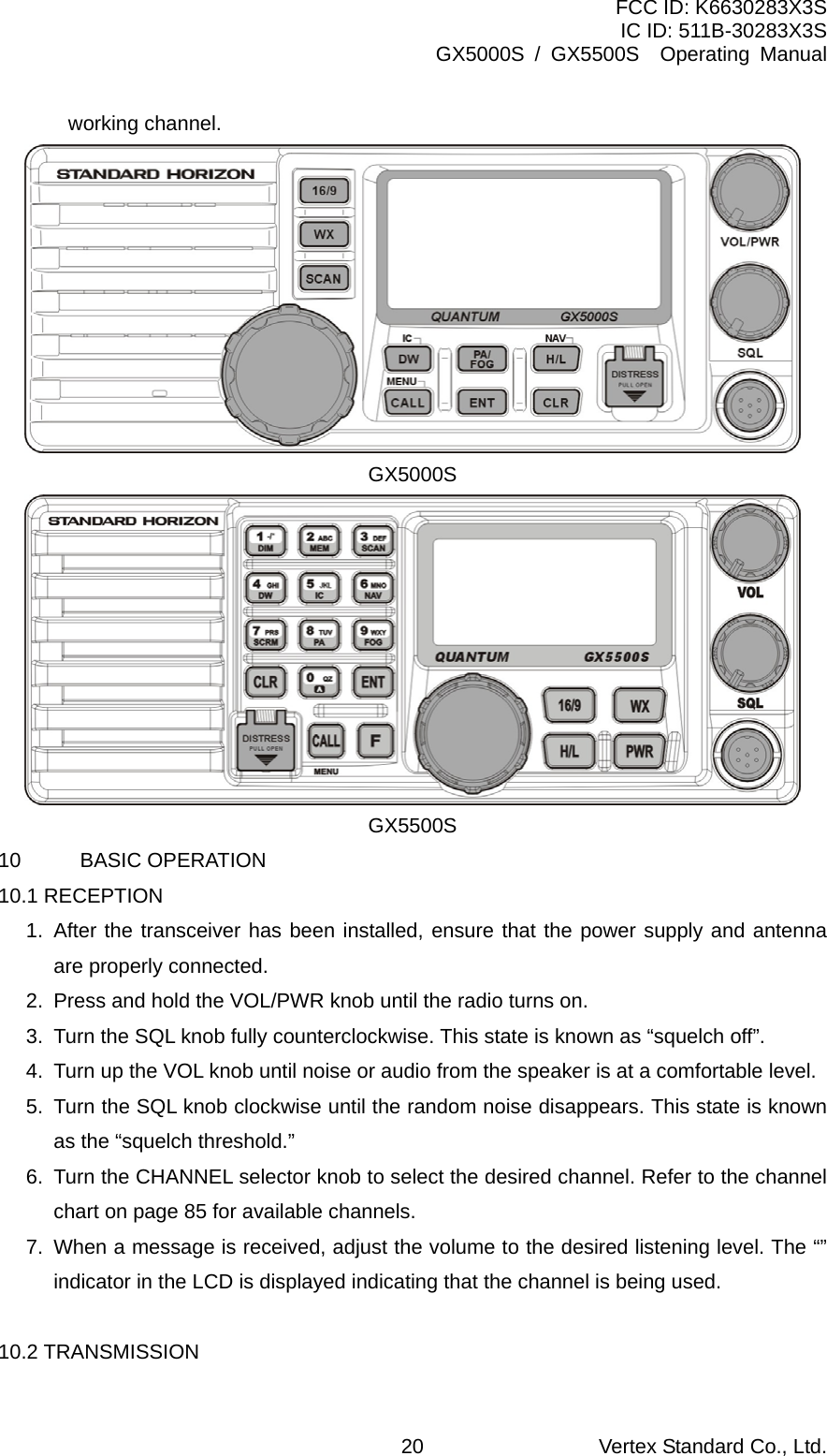
![FCC ID: K6630283X3S IC ID: 511B-30283X3S GX5000S / GX5500S Operating Manual CHANNEL SELECTOR KNOB The rotary knob is used to select channels and to choose menu items (such as the DSC menu, radio setup menu, and DSC setup menu). The [UP (p)] / [DOWN (q)] keys on the microphone can also be used to select channels and menu items. Secondary Use While holding down the [SCAN (MEM)] key and turning the CHANNEL selector knob, you can confirm memory channels for scanning. KEYPAD [16/9] Key Immediately recalls channel 16 from any channel location and automatically selects high power. Pressing the [16/9] key again reverts to the previous selected working channel. Secondary use Press and hold the [16/9] key then press the [WX] key to switch between the USA, Canadian and International Channel Groups. [WX] Key Immediately recalls the previously selected NOAA weather channel from any channel. Secondary use Holding down the [16/9] key while pressing the [WX] key changes from USA, International and Canadian channel groups. [PA/FOG] Key (GX5000S) Operates the 30 W PA function and/or the FOG HORN function when an external horn and/or speaker is connected. [SCAN (MEM)] Key (GX5000S) Press this key to start and stop the scanning of programmed channels. Refer to section “8.12 SCANNING” for details. Secondary use To add a channel into the scan memory, select the channel and press and hold the [SCAN (MEM)] key until “MEM” is shown on the display. To delete a memorized channel from scan memory, select the channel and press and hold the [SCAN (MEM)] key until “MEM” is removed from the display. Vertex Standard Co., Ltd. 14](https://usermanual.wiki/Yaesu-Musen/30283X3S/User-Guide-766711-Page-14.png)
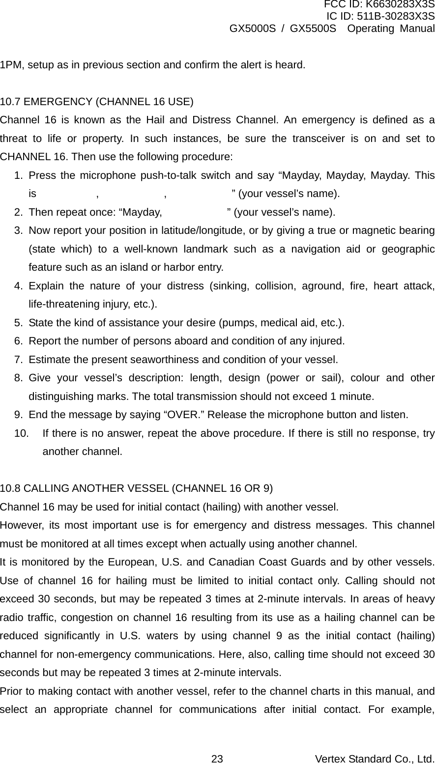
![FCC ID: K6630283X3S IC ID: 511B-30283X3S GX5000S / GX5500S Operating Manual [DW/IC]] Key (GX5000S) Pressing this key enables dual watch between a priority channel (Ch16 is the default) and a selected channel until a signal is received. When a signal is received on the selected channel the radio will momentarily switch to the Priority channel and listen for communications. Refer to section “8.11 DUAL WATCH (TO PRIORITY CHANNEL)” for details. Secondary use Press and hold this key, when the optional RAM+ Mic or VH-310 Handset is connected, intercom operation will operate between radio and option mic or handset. Refer to section “8.15 INTERCOM OPERATION” for details. [H/L (NAV)] Key (GX5000S) ([H/L] key for GX5500S) Press this key to toggle the transmit output power between 25 W (High) and 1 W (Low) power. When the [H/L (NAV)] key is pressed while the transceiver is on channel 13 or 67, the power will temporarily switch from LO to HI power until the PTT is released. The [H/L (NAV)] key does not function on transmit inhibited and low power only channels. NOTE: 1W low power is indicated by LO on the display, when 25W high power is selected the display do not show an indication. Secondary use Press and hold this key, the LCD displays NAV GPS Data, Time, SOG (Speed Over Ground), and COG (Course Over Ground) when a GPS is connected to the accessory cable of the GX5000S/GX5500S. See section “6.3 ACCESSORY CABLE” for details. [1(DIM)] Key (GX5500S) When in radio mode, this key is used to directly select channel digit “1” in a channel number. Secondary use Press the [F] key first then press the [1(DIM)] key, access the LCD Dimmer menu. Refer to section “10.15 LCD DIMMER” for details. Vertex Standard Co., Ltd. 15](https://usermanual.wiki/Yaesu-Musen/30283X3S/User-Guide-766711-Page-15.png)
![FCC ID: K6630283X3S IC ID: 511B-30283X3S GX5000S / GX5500S Operating Manual [2(MEM)] Key (GX5500S) When in radio mode, this key is used to directly select channel digit “2” in a channel number. Secondary use (Depends on the transceiver version) Press the [F] key first then press the [2(MEM)] key, memorize the selected channel into the transceiver scan memory for scanning. When repeat the same procedures ([F] _ [2(MEM)]), DELETES the channel from the scan memory. Refer to section “10.12 SCANNING” for details. [3(SCAN)] Key (GX5500S) When in radio mode, this key is used to directly select channel digit “3” in a channel number. Secondary use (Depends on the transceiver version) Press the [F] key first then press the [3(SCAN)] key, start and stop the scanning of programmed channels. Refer to section “10.12 SCANNING” for details. [4(DW)] Key (GX5500S) When in radio mode, this key is used to directly select channel digit “4” in a channel number. Secondary use (Depends on the transceiver version) Press the [F] key first then press the [4(DW)] key, scan for voice communications on the priority channel and another selected channel until a signal is received on either channel (Dual Watch). Refer to section “10.11 DUAL WATCH (TO PRIORITY CHANNEL)” for details. [5(IC)] Key (GX5500S) When in radio mode, this key is used to directly select channel digit “5” in a channel number. Vertex Standard Co., Ltd. 16](https://usermanual.wiki/Yaesu-Musen/30283X3S/User-Guide-766711-Page-16.png)
![FCC ID: K6630283X3S IC ID: 511B-30283X3S GX5000S / GX5500S Operating Manual Secondary use Press the [F] key first then press the [5(IC)] key, when the optional RAM+ Mic is connected, intercom operation will operate between radio and RAM+ Mic. Refer to section “10.16 INTERCOM OPERATION” for details. [6(NAV)] Key (GX5500S) When in radio mode, this key is used to directly select channel digit “6” in a channel number. Secondary use Press the [F] key first then press the [6(NAV)] key, the LCD displays NAV GPS Data, Time, SOG (Speed Over Ground), and COG (Course Over Ground) when a GPS is connected to the accessory cable of the GX3500S. See section “8.4 CONNECTION OF GPS WITH NMEA OUTPUT” for details. [7(SCRM)] Key (GX5500S) When in radio mode, this key is used to directly select channel digit “7” in a channel number. Secondary use Press the [F] key first then press the [7(SCRM)] key, when the optional CVS2500 Voice Scrambler Unit is installed, available to operate the Voice Scrambler function. Refer to section “10.17 VOICE SCRAMBLER” for details. [8(PA)] Key (GX5500S) When in radio mode, this key is used to directly select channel digit “8” in a channel number. Secondary use Press the [F] key first then press the [8(PA)] key, available to operate the 30 Watt PA function. Refer to section “10.13 PA/FOG OPERATION” for details. Vertex Standard Co., Ltd. 17](https://usermanual.wiki/Yaesu-Musen/30283X3S/User-Guide-766711-Page-17.png)
![FCC ID: K6630283X3S IC ID: 511B-30283X3S GX5000S / GX5500S Operating Manual [9(FOG)] Key (GX5500S) When in radio mode, this key is used to directly select channel digit “9” in a channel number. Secondary use Press the [F] key first then press the [9(FOG)] key, available to operate the Fog Horn function. Refer to section “10.13 PA/FOG OPERATION” for details. [0] Key (GX5500S) When in radio mode, this key is used to directly select channel digit “0” in a channel number. [CALL (MENU)] Key (GX5500S) Press the [CALL (MENU)] key to access the DSC OPERATION menu. The “INDIVIDUAL CALL,” “GROUP CALL,” and “ALL SHIPS CALL” functions can be accessed from the DSC OPERATION menu. NOTE: Before operating DSC a MMSI must be entered. Refer to section “9.2 MARITIME MOBILE SERVICE IDENTITY (MMSI).” Secondary use Press and hold the [CALL (MENU)] key to access the “Radio Setup” (refer to section “10 RADIO SETUP MODE”) or “DSC Setup” menu (refer to section “9 DIGITAL SELECTIVE CALLING”). [ENT] Key Press the [ENT] Key to enter the menu selection. [CLR] Key Press the [CLR] Key to cancel the menu selection. [DISTRESS] Key Used to send a DSC Distress Call. To send the distress call refer to section “9.3.1 (Transmitting A DSC Distress Alert).” Vertex Standard Co., Ltd. 18](https://usermanual.wiki/Yaesu-Musen/30283X3S/User-Guide-766711-Page-18.png)
![FCC ID: K6630283X3S IC ID: 511B-30283X3S GX5000S / GX5500S Operating Manual ANTENNA JACK Connects an antenna to the transceiver. Use a marine VHF antenna with an impedance of 50 ohms. REMOTE MIC CONNECTORS Connects the GX5000S/GX5500S to the enhanced RAM+ MIC (Remote Access Microphone) or the VH-310 Handset. Refer to section “11 ENHANCED RAM+ MIC OPERATION” or “12 VH-310 HEADSET OPERATION” for details. ACCESSORY CONNECTION CABLE Connects the GX5000S/GX5500S to a GPS, a PA speaker, and an external speaker. DC INPUT CABLE Connects the radio to a DC power supply capable of delivering 13.8V DC. PTT (Push-To-Talk) SWITCH Keys the transmitter when the transceiver is in radio mode. If the transceiver is in the intercom mode (between the CMP25 RAM+ or VH-310 Headset and the GX5000S/GX5500S), or PA mode, it activates the GX5000S/GX5500S microphone for voice communications. MICROPHONE Transmits the voice message with reduction of background noise, using Clear Voice Noise Reduction Technology. NOTE: Be sure your mouth is about 1.5 cm from the mic hole for best performance. [UP (p)] / [DOWN (q)] KEYS The [UP (p)] and [DOWN (q)] on the microphone function the same as the CHANNEL selector knob on the front panel of the transceiver. [16/9] Key The [16/9] key on the microphone functions the same as the [16/9] key on the front panel of the transceiver. Immediately recalls channel 16 from any channel location. Holding down this key recalls channel 9. Pressing the [16/9] key again reverts to the previous selected Vertex Standard Co., Ltd. 19](https://usermanual.wiki/Yaesu-Musen/30283X3S/User-Guide-766711-Page-19.png)
![FCC ID: K6630283X3S IC ID: 511B-30283X3S GX5000S / GX5500S Operating Manual 1. Perform steps 1 through 6 of RECEPTION. 2. Before transmitting, monitor the channel to ensure it is clear. 3 Press the PTT (push-to-talk) switch. The “” indicator in the LCD is displayed. 4. Speak slowly and clearly into the microphone. 5. When the transmission is finished, release the PTT switch. NOTE This is a noise-canceling microphone. The oval slot on the bottom of microphone should be positioned within 1.5 cm from the mouth for optimum performance. 10.3 TRANSMIT TIME - OUT TIMER (TOT) When the PTT switch on the microphone is held down, transmit time is limited to 5 minutes. This limits unintentional transmissions due to a stuck microphone. About 10 seconds before automatic transmitter shutdown, a warning beep will be heard from the speaker(s). The transceiver will automatically go to receive mode, even if the PTT switch is continually held down. Before transmitting again, the PTT switch must first be released and then pressed again. NOTE When a transmission was shut down by the TOT, the GX5000S/GX5500S can not transmit afterwards for 10 seconds. 10.4 SIMPLEX/DUPLEX CHANNEL USE Refer to the VHF MARINE CHANNEL CHART (page 91) for instructions on use of simplex and duplex channels. NOTE All channels are factory-programmed in accordance with International, Industry Canada (Canada), and FCC (USA) regulations. Mode of operation cannot be altered from simplex to duplex or vice-versa. 10.5 INTERNATIONAL, USA, AND CANADA MODE 1. To change the modes, hold the [16/9] key and press the [WX] key. The mode changes from International to Canadian to USA with each press of the [WX] key. 2. “INTL” will be displayed for International mode, “CAN” will be displayed for Canadian mode, and “USA” will be displayed on the LCD for USA mode. 3. Refer to the VHF MARINE CHANNEL CHART (page 91) for allocated channels in each mode. Vertex Standard Co., Ltd. 21](https://usermanual.wiki/Yaesu-Musen/30283X3S/User-Guide-766711-Page-21.png)
![FCC ID: K6630283X3S IC ID: 511B-30283X3S GX5000S / GX5500S Operating Manual 10.6 NOAA WEATHER CHANNELS NOTE NOAA Weather channels are available in the waters of USA and Canada only. 1. To receive a NOAA weather channel, press the [WX] key from any channel. The transceiver will go to the last selected weather channel. 2. Turn the CHANNEL selector knob on the radio or [UP(p)] / [DOWN(q)] keys on the microphone to select a different NOAA weather channel. 3. To exit from the NOAA weather channels, press the [WX] key. The transceiver returns to the channel it was on prior to a weather channel. 10.6.1 NOAA Weather Alert In the event of extreme weather disturbances, such as storms and hurricanes, the NOAA (National Oceanic and Atmospheric Administration) sends a weather alert accompanied by a 1050 Hz tone and subsequent weather report on one of the NOAA weather channels. When the Weather Alert feature is enabled (see section “10.10 WX ALERT”), the transceiver is capable of receiving this alert if the following is performed: 1. Program NOAA weather channels into the transceiver’s memory for scanning. Follow the same procedure as for regular channels under section “9.12 SCANNING.” 2. Press the [SCAN (MEM)] key once to start memory scanning or priority scanning (determined from the “10.7 SCAN TYPE” section, see page 60 for details). 3. The programmed NOAA weather channels will be scanned along with the regular-programmed channels. However, scanning will not stop on a normal weather broadcast unless a NOAA alert is received. 4. When an alert is received on a NOAA weather channel, scanning will stop and the transceiver will emit a loud beep to alert the user of a NOAA broadcast. 5. Press the [WX] key to stop the alert tone and receive the weather report. NOTE If the [WX] key is not pressed the alert tone will be emitted for 5 minutes and then the weather report will be received. NOTE The Weather Alert feature is also engaged while the transceiver is receiving on one of the NOAA weather channels. 10.6.2 NOAA Weather Alert Testing NOAA tests the alert system every Wednesday between 11AM and 1PM. To test the GX5000S/GX5500S’s NOAA Weather alert feature, on Wednesday between 11AM and Vertex Standard Co., Ltd. 22](https://usermanual.wiki/Yaesu-Musen/30283X3S/User-Guide-766711-Page-22.png)
![FCC ID: K6630283X3S IC ID: 511B-30283X3S GX5000S / GX5500S Operating Manual Channels 68 and 69 are some of the channels available to non-commercial (recreational) boaters. Monitor your desired channel in advance to make sure you will not be interrupting other traffic, and then go back to either channel 16 or 9 for your initial contact. When the hailing channel (16 or 9) is clear, state the name of the other vessel you wish to call and then “this is” followed by the name of your vessel and your Station License (Call Sign). When the other vessel returns your call, immediately request another channel by saying “go to,” the number of the other channel, and “over.” Then switch to the new channel. When the new channel is not busy, call the other vessel. After a transmission, say “over,” and release the microphone’s push-to-talk (PTT) switch. When all communication with the other vessel is completed, end the last transmission by stating your Call Sign and the word “out.” Note that it is not necessary to state your Call Sign with each transmission, only at the beginning and end of the contact. Remember to return to Channel 16 when not using another channel. Some radios automatically monitor Channel 16 even when set to other channels or when scanning. 10.9 MAKING TELEPHONE CALLS To make a radiotelephone call, use a channel designated for this purpose, The fastest way to learn which channels are used for radiotelephone traffic is to ask at a local marina. Channels available for such traffic are designated Public Correspondence channels on the channel charts in this manual. Some examples for USA use are Channels 24, 25, 26, 27, 28, 84, 85, 86, and 87. Call the marine operator and identify yourself by your vessel’s name, The marine operator will then ask you how you will pay for the call (telephone credit card, collect, etc.) and then link your radio transmission to the telephone lines. The marine telephone company managing the VHF channel you are using may charge a link-up fee in addition to the cost of the call. 10.10 OPERATING ON CHANNELS 13 AND 67 Channel 13 is used at docks and bridges and by vessels maneuvering in port. Messages on this channel must concern navigation only, such as meeting and passing in restricted waters. Channel 67 is used for navigational traffic between vessels. By regulation, power is normally limited to 1 Watt on these channels. Your radio is programmed to automatically reduce power to this limit on these channels. However, in certain situations it may be necessary to temporarily use a higher power. See page 20 ([H/L(NAV)] key) for means to temporarily override the low-power limit on these two channels. Vertex Standard Co., Ltd. 24](https://usermanual.wiki/Yaesu-Musen/30283X3S/User-Guide-766711-Page-24.png)
![FCC ID: K6630283X3S IC ID: 511B-30283X3S GX5000S / GX5500S Operating Manual 10.11 DUAL WATCH (TO PRIORITY CHANNEL) Dual watch allows the radio to monitor one channel and the assigned Priority channel. By default the priority channel is set to 16, however the priority channel may be changed by referring to section “10.6 PRIORITY CHANNEL SET.” 1. Adjust the SQL knob until the background noise disappears. 2. Select the channel you wish to dual watch to “Priority channel.” 3. Press the [DW (IC)] key. The display will scan between Priority channel and the channel that was selected in step 2. If a transmission is received on the channel selected in step 2, the GX5000S/GX5500S will dual watch between the working channel and the Priority channel. 4. To stop Dual Watch, press the [DW (IC)] key again. 10.12 SCANNING Allows the user to select the scan type from Memory scan or Priority scan. “Memory scan” scans the channels that were programmed into memory. “Priority scan” scans the channels programmed in memory with the priority channel. 10.12.1 Selecting the Scan Type 1. Press and hold down the [CALL (MENU)] key until “Radio Setup” menu appears. 2. Press the [ENT] key, then select “SCAN Type” in the “Radio Setup” menu with the CHANNEL selector knob. 3. Press the [ENT] key. 4. Turn the CHANNEL selector knob to select “Priority” or “Memory.” 5. Press the [ENT] key to store the selected setting. 6. To exit this menu and return to radio operation mode press the [16/9] key. 10.12.2 Memory Scanning (M-SCAN) 1. Adjust the SQL knob until background noise disappears. 2. Select a desired channel to be scanned using the CHANNEL selector knob. Press and hold the [SCAN (MEM)] key for one second, “MEM” will appear on the LCD, which indicates the channel has been programmed into the transceivers memory. 3. Repeat step 2 for all the desired channels to be scanned. 4. To DELETE a channel from the transceiver’s memory, select the channel then press Vertex Standard Co., Ltd. 25](https://usermanual.wiki/Yaesu-Musen/30283X3S/User-Guide-766711-Page-25.png)
![FCC ID: K6630283X3S IC ID: 511B-30283X3S GX5000S / GX5500S Operating Manual and hold the [SCAN (MEM)] key for one second, “MEM” will disappear in the LCD. 5. To start scanning, just press the [SCAN (MEM)] key momentarily. “M-SCAN” appears on the LCD. Scanning will proceed from the lowest to the highest programmed channel number and will stop on a channel when a transmission is received. 6. The channel number will blink during reception. 7. To stop scanning, press the [16/9] or [WX] key. 10.12.3 Priority Scanning (P-SCAN) In the default setting, Channel 16 is set as the priority channel. You may change the priority channel to the desired channel from the Channel 16 by the Radio Setup Mode, refer to section “10.6 PRIORITY CHANNEL SET.” 1. Adjust the SQL knob until background noise disappears. 2. Select a desired channel to be scanned using the CHANNEL selector knob. Press and hold the [SCAN (MEM)] key (GX5000S) for one second, “MEM” will appear on the display, which indicates the channel has been programmed into the transceivers memory. 3. Repeat step 2 for all the desired channels to be scanned. 4. To DELETE a channel from the transceiver’s memory, select the channel then press and hold the [SCAN (MEM)] key (GX5000S) until “MEM” is removed from the display. 5. To start priority scanning, press the [SCAN (MEM)] key (GX5000S) momentarily. “P-SCAN” appears on the LCD. Scanning will proceed between the memorized channels and the priority channel. The priority channel will be scanned after each programmed channel. 6. To stop scanning, press the [16/9] or [WX] key. You may change the scan resume time in the Radio Setup Mode, refer to section “10.8 SCAN RESUME TIME.” 10.13 PA/FOG OPERATION PA/FOG mode allows the transceiver to be used as a 30W hailer when an optional STANDARD HORIZON 220SW or 240SW PA horn speaker is installed. When in Hail mode the PA speaker Listen’s Back (acts as a microphone and amplifies sound to the front panel speaker) through the PA horn speaker, which provides two-way communications through the PA horn speaker. NOTE When in PA or FOG mode the GX5000S/GX5500S will receive on the last selected VHF Vertex Standard Co., Ltd. 26](https://usermanual.wiki/Yaesu-Musen/30283X3S/User-Guide-766711-Page-26.png)
![FCC ID: K6630283X3S IC ID: 511B-30283X3S GX5000S / GX5500S Operating Manual channel before entering into the PA or FOG mode and receive DSC calls. PA HAIL mode: PA HAIL mode allows the transceiver to be used as a power hailer when an optional STANDARD HORIZON 220SW or 240 SW HAIL/PA speaker is installed. The Hail mode has a listen-back feature, which provides two-way communication through the HAIL/PA speaker. FOG HORN mode: Automatic signaling is transmitted through the HAIL/PA speaker. 10.13.1 Operating the PA HAIL mode 1. Press the [PA/FOG] key (GX5000S), then select “PA” with the CHANNEL selector knob. 2. Press the [ENT] key. 3. Press the PTT switch to speak through the HAIL/PA speaker. Rotate the CHANNEL selector knob to control the AF output level. The AF output level can be set from 0 to 30 watts. 4. To exit the PA HAIL mode, press the [PA/FOG] (GX5000S) or [CLR] key. 10.13.2 Operating the FOG HORN mode Operator can select from “Underway,” “Stop,” “Sail,” “Tow,” “Aground,” “Anchor,” “Horn,” or “Siren.” Please refer to page 95 for FOG Horn Timing Chart. 1. Press the [PA/FOG] key (GX5000S), then select “Fog” with the CHANNEL selector knob. 2. Press the [ENT] key. 3. Turn the CHANNEL selector knob to select the one of the eight functions described above. 4. Press the [ENT] key. 5. On the “Horn” and “Siren” modes, press the PTT switch to activate the tone through the HAIL/PA speaker. Rotate the CHANNEL selector knob to control the AF output level. The AF output level can be set from 0 to 30 watts. 6. To exit the FOG HORN mode, press the [PA/FOG] or [CLR] key. 10.14 NAVIGATION INDICATION The transceiver has the ability to display Time, SOG, COG, as well as the position Vertex Standard Co., Ltd. 27](https://usermanual.wiki/Yaesu-Musen/30283X3S/User-Guide-766711-Page-27.png)
![FCC ID: K6630283X3S IC ID: 511B-30283X3S GX5000S / GX5500S Operating Manual (LAT/LON), when connected to a GPS receiver. 1. Press and hold the [H/L(NAV)] key, display the position information on the LCD. If the GPS receiver is not receiving a fix, the display will be as shown in the illustration on the right. NOTE: When Ch16 is selected only lat/lon will shown. 2. To hide the position information, press and hold the [H/L(NAV)] key again. 10.15 INTERCOM OPERATION Connecting a CMP25 RAM+ or VH-310 handset to the GX5000S/GX5500S allows intercom communications. Refer to section “11.3 INTERCOM OPERATION” for CMP25 RAM+ Microphone or section “12.3 INTERCOM OPERATION” for VH-310 Handset. 10.15.1 Communication 1. Press and hold the [DW(IC)] key, the mode is changed to “INTERCOM” mode. 2. If your GX5000S/GX5500S is equipped with two CMP25 RAM+ Mic’s (or VH-310 Handset), select the companion you wish to communicate (Ram1, Ram2, or ALL) with the CHANNEL selector knob, then press the [ENT] key. 3. When the “INTERCOM” is activated, “Intercom” is displayed on the GX5000S/GX5500S, and “IC” is displayed on the CMP25 RAM+ Mic or VH-310 Handset. 4. Press the PTT switch. “Talk” will be shown on the display. NOTE: A warning beep will be emitted when the GX5000S/GX5500S microphone’s PTT switch is pressed while the RAM+ Mic’s or VH-310 Handset’s PTT switch is pressed. 5. Speak slowly and clearly into the microphone, hold the microphone about 1.5 cm away from your mouth. 6. When finished, release the PTT switch. 7. To exit the “INTERCOM” mode and return to radio operation mode, press the [16/9] or [CLR] key. 10.15.2 Calling While in INTERCOM mode, pressing and holding the [DW(IC)] key on the GX5000S/GX5500S, CMP25, or VH-310 will produce a calling beep at the other station. NOTE When both CMP25 RAM+ microphones (or VH-310 Handset) are intercom mode, the GX5000S/GX5500S will be temporarily disabled until the RAM+(s) exit the RAM+ to RAM+ Vertex Standard Co., Ltd. 28](https://usermanual.wiki/Yaesu-Musen/30283X3S/User-Guide-766711-Page-28.png)
![FCC ID: K6630283X3S IC ID: 511B-30283X3S GX5000S / GX5500S Operating Manual 11.2 MARITIME MOBILE SERVICE IDENTITY (MMSI) 11.2.1 What is an MMSI? An MMSI is a nine-digit number used on Marine Transceivers capable of using Digital Selective Calling (DSC). This number is used like a telephone number to selectively call other vessels. THIS NUMBER MUST BE PROGRAMMED INTO THE RADIO TO OPERATE THE GX5000S/GX5500S DSC FUNCTIONS. How can I obtain an MMSI assignment? Please contact the Radio Licensing Authority for your country for information on how to obtain an MMSI number. 11.2.2 Programming the MMSI WARNING A user MMSI can be input only once. If the user tries to input an MMSI more than once the radio will show the display on the right. Therefore please be careful not to input the incorrect MMSI number. If the user needs to change the MMSI number after it has been entered, the radio will have to be returned to Factory Service. Refer to the section “14.2. FACTORY SERVICE.” 1. Press and hold down the [CALL (MENU)] key until the “Radio Setup” menu appears. 2. Turn the CHANNEL selector knob to the left to select “DSC Setup” menu. 3. Press the [ENT] key, then select “User MMSI” with the CHANNEL selector knob. 4. Press the [ENT] key. The display will show a series of dashes or the last MMSI number if programmed. 5. Turn the CHANNEL selector knob or press the [UP(p)] / [DOWN(q)] key on the microphone to select the first number of your MMSI, then press the [ENT] key to step to the next number. 6. Repeat step 5 to set your MMSI (up to nine digits). 7. When finished programming the number, press and hold the [ENT] key until the confirmation message appears. 8. Press the [ENT] key to store the number in memory and return to radio operation mode. 11.3 DSC DISTRESS ALERT The GX5000S/GX5500S is capable of transmitting and receiving DSC Distress messages to all DSC radios. The GX5000S/GX5500S may be connected to a GPS to also transmit the Latitude and Longitude of the vessel. Vertex Standard Co., Ltd. 30](https://usermanual.wiki/Yaesu-Musen/30283X3S/User-Guide-766711-Page-30.png)
![FCC ID: K6630283X3S IC ID: 511B-30283X3S GX5000S / GX5500S Operating Manual 11.3.1 Transmitting a DSC Distress Alert NOTE To be able to transmit a DSC Distress Alert an MMSI number must be programmed, refer to section “11.2.2 Programming the MMSI.” In order for your vessels location to be transmitted either connect a GPS to the GX5000S/GX5500S (refer to section “6.3 ACCESSORY CABLE”) or manually input your position (refer to section “11.11 MANUALLY INPUTTING GPS LOCATION”). 1. Lift the red spring loaded DISTRESS cover, then press and hold the [DISTRESS] key. The “DISTRESS” menu will appear on the LCD and the radios display will count down (5-4-3-2-1) and then transmit the Distress Alert. The backlight of the LCD and keypad flashes while the radios display is countdown. 2. When the distress signal is sent, CH70 and the “” icon will appear on the LCD. 3. The transceiver will watch for a DSC acknowledgment transmission on CH70 and also receive calls on CH16. 4. If an acknowledgement is received, select channel 16 and advise your distress situation. 5. If no acknowledgment is received, the Distress Alert is repeated at 4 minute intervals until a DSC acknowledgment is received. 6. When a DSC Distress acknowledgment is received, a distress alarm sounds and channel 16 is automatically selected. The LCD shows the MMSI of the ship responding to your distress. RECEIVED ACK: acknowledgment signal is received. RECEIVED RLY ACK: relay acknowledgment signal is received from another vessel or coast station. 8. To cancel the DSC Distress alarm signal from the speaker, press any key. Transmitting a DSC Distress Alert with Nature of Distress. The GX5000S/GX5500S is capable of transmitting a DSC Distress Alert with the following “Nature of Distress” categories: Undesignated, Fire, Flooding, Collision, Grounding, Capsizing, Sinking, Adrift, Abandoning, Piracy, MOB 1. Lift the red spring loaded DISTRESS cover and press the [DISTRESS] key. The “DISTRESS” menu will appear on the LCD. 2. Turn the CHANNEL selector knob to select the desired nature of distress category. 3. Press and hold the [DISTRESS] key. The radios display will count down (5-4-3-2-1) Vertex Standard Co., Ltd. 31](https://usermanual.wiki/Yaesu-Musen/30283X3S/User-Guide-766711-Page-31.png)
![FCC ID: K6630283X3S IC ID: 511B-30283X3S GX5000S / GX5500S Operating Manual and then transmit the Distress call. The backlight of the LCD and keypad flashes while the radios display is countdown. 4. When the distress signal is sent, CH70 and “” icon will appear on the LCD. 5. The transceiver will watch for a DSC acknowledgment transmission on CH70 and also receive calls on CH16. 6. If an acknowledgement is received, select channel 16 and advise your distress situation. 7. If no acknowledgment is received, the Distress Alert is repeated in 4 minute intervals until a DSC acknowledgment is received. 8. When a DSC Distress acknowledgment is received, a distress alarm sounds and channel 16 is automatically selected. The LCD shows the MMSI of the ship responding to your distress. RECEIVED ACK: acknowledgment signal is received. RECEIVED RLY ACK: relay acknowledgment signal is received from another vessel or coast station. 9. To cancel the DSC Distress alarm signal from the speaker, press any key. Cancel the DSC Distress Repeat Call In order to cancel the repeat call function of the DSC, press the [CLR] key, then press the [ENT] key. 11.3.2 Receiving a DSC Distress Alert 1. When a DSC Distress Alert is received, an emergency alarm sounds. Then channel 16 is automatically selected. 2. Press any key to stop the alarm. 3. Turn the CHANNEL selector knob to change the display to show the position of the vessel in distress. 4 If the position of the vessel distress data does not include position, the LCD will show the display on the right. NOTE When there is an unread Distress Alert, the “DSC” icon will blink. You may review the unread Distress Alert from the DSC Log, refer to section “11.6.2 Reviewing Received Calls Logged into the Call Waiting Directory.” NOTE You must continue monitoring channel 16 as a coast station may require assistance in the Vertex Standard Co., Ltd. 32](https://usermanual.wiki/Yaesu-Musen/30283X3S/User-Guide-766711-Page-32.png)
![FCC ID: K6630283X3S IC ID: 511B-30283X3S GX5000S / GX5500S Operating Manual rescue attempt. 11.3.3 Distress Relay The Distress Relay allows you to send (relay) the received Distress Alert to other vessel. 1. Press the [CALL (MENU)] key. The “DSC Operation” menu will appear. 2. Turn the CHANNEL selector knob to select “DSC Log” menu. 3. Press the [ENT] key, then select “Distress” with the CHANNEL selector knob. 4. Press the [ENT] key, then select the station (name or MMSI number) to be sent (relay) the received Distress Alert with the CHANNEL selector knob. 5. Press the [ENT] key. 6. Turn the CHANNEL selector knob to select the “Individual” you want to send (relay) the received Distress Alert, if you have already set up the Individual Directory (refer to section “11.5.1 Setting up the Individual / Position Call Directory” for setting) or “Manual,” then press the [ENT] key. 7. When “Manual” is selected at the previous step, enter the MMSI number (nine digits) to which you want to send (relay) the received Distress Alert. To do this, turn the CHANNEL selector knob to scroll through numbers “0-9,” the press the [ENT] key to move the entry location to the right. If a mistake was made entering in the MMSI number repeat pressing the [H/L(NAV)] key until the wrong nunber is selected, then move the channel knob to correct the entry. When finished entering the MMSI number, press and hold the [ENT] key. 8. Press the [ENT] key again to transmit the Distress Relay signal. 11.4 ALL SHIPS CALL The All Ships Call function allows contact to be established with other vessel stations without having their ID in the individual calling directory. Also, priority for the call can be designated as Ugency or Safety. URGENCY Call: This type of call is used when a vessel may not truly be in distress, but have a potential problem that may lead to a distress situation. This call is the same as saying PAN PAN PAN on channel 16. SAFETY Call: Used to transmit boating safety information to other vessels. This message usually contains information about an overdue boat, debris in the water, loss of a navigation aid or an important meteorological message. This call is the same as saying “Securite, Securite, Securite.” 11.4.1 Transmitting an All Ships Call Vertex Standard Co., Ltd. 33](https://usermanual.wiki/Yaesu-Musen/30283X3S/User-Guide-766711-Page-33.png)
![FCC ID: K6630283X3S IC ID: 511B-30283X3S GX5000S / GX5500S Operating Manual 1. Press the [CALL (MENU)] key. The “DSC Operation” menu will appear. 2. Turn the CHANNEL selector knob to select “All Ships.” 3. Press the [ENT] key. (To cancel, turn the CHANNEL selector knob to select “Exit.”) 4. Turn the CHANNEL selector knob to select the call (“Urgency” or “Safety”). 5. Press the [ENT] key to transmit the selected type of all ships DSC call. 6. After the ALL SHIPS CALL is transmitted, the transceiver will switch to CH16. 7. Listen to the channel to make sure it is not busy, then key the microphone and say PAN PAN PAN or “Securite, Securite, Securite” depending on the priority of the call. Say your call sign and announce the channel you wish to switch to for communications. 11.4.2 Receiving an All Ships Call 1. When an all ships call is received, an emergency alarm sounds. The radio will automatically change to channel 16. 2. Press any key to stop the alarm. 3. Turn the CHANNEL selector knob to see the MMSI of the vessel transmitting the All Ships Call. 4. Monitor channel 16 or traffic channel until the URGENCY voice communication is completed. NOTE When there is an unread All Ships Call, the “DSC” icon will blink. You may review the unread All Ship Call from the DSC Log, refer to section “11.6.2 Reviewing Received Calls Logged into the Call Waiting Directory.” 11.5 INDIVIDUAL CALL This feature allows the GX5000S/GX5500S to contact another vessel with a DSC VHF radio and automatically switch the receiving radio to a desired communications channel. This feature is similar to calling a vessel on CH16 and requesting to go to another channel (switching to the channel is private between the two stations). 11.5.1 Setting up the Individual / Position Call Directory The GX5000S/GX5500S has a DSC directory that allows you to store a vessel or person’s name and the MMSI number associated with vessels you wish to transmit Individual calls, Position Requests and Position Send transmissions. To transmit an Individual call you must program this directory with the information of the Vertex Standard Co., Ltd. 34](https://usermanual.wiki/Yaesu-Musen/30283X3S/User-Guide-766711-Page-34.png)
![FCC ID: K6630283X3S IC ID: 511B-30283X3S GX5000S / GX5500S Operating Manual persons you wish to call, similar to a cellular phones directory. 1. Press and hold down the [CALL (MENU)] key until “Radio Setup” menu appears. 2. Turn the CHANNEL selector knob to select “DSC Setup” menu. 3. Press the [ENT] key, then select “INDIV DIR” with the CHANNEL selector knob. 4. Press the [ENT] key, then select “Add” with the CHANNEL selector knob. 5. Press the [ENT] key. 6. Turn the CHANNEL selector knob to scroll to the first letter of the name of the vessel or person you want to list in the directory. 7. Press the [ENT] key to store the first letter of the name and step to the next letter to the right. 8. Repeat step 6 and 7 until the name is complete. The name can consist of up to eleven characters, if you do not use all eleven characters press the [ENT] key to move to the next space. This method can also be used to enter a blank space in the name. To clear the previous letter, press the [CLR] key. 9. After the eleventh letter or space has been entered, press and hold the [ENT] key to advance to the MMSI Maritime Mobile Service Identity Number number entry. 10. Turn the CHANNEL selector knob to scroll through numbers, 0-9. To enter the desired number and move one space to the right press the [ENT] key. Repeat this procedure until all nine spaces of the MMSI number are entered. 11. If a mistake was made entering in the name or the MMSI number repeat pressing the [H/L(NAV)] key until the wrong character is selected, then move the channel knob to correct the entry. 12. To store the data entered, press and hold the [ENT] key. 13. To enter another individual address, repeat steps 4 through 12. 14. To exit this menu and return to radio operation mode press the [16/9] key. NOTE Selecting “Next” or “Exit” will automatically save the name and MMSI number into memory. 11.5.2 Setting up Individual Reply Allows setting up the radio to automatically (default setting) or manually respond to a DSC Individual call requesting you to switch to a working channel for voice communications. When Manual is selected the MMSI of the calling vessel is shown allowing you to see who is calling. This function is similar to caller id on a cellular phone. 1. Press and hold down the [CALL (MENU)] key until “Radio Setup” menu appears. 2. Turn the CHANNEL selector knob to select “DSC Setup” menu. Vertex Standard Co., Ltd. 35](https://usermanual.wiki/Yaesu-Musen/30283X3S/User-Guide-766711-Page-35.png)
![FCC ID: K6630283X3S IC ID: 511B-30283X3S GX5000S / GX5500S Operating Manual 3. Press the [ENT] key, then select “INDIV Reply” with the CHANNEL selector knob. 4. Press the [ENT] key. 5. Turn the CHANNEL selector knob to select “Auto” or “Manual.” 6. Press the [ENT] key to store the selected setting. 7. To exit this menu and return to radio operation mode press the [16/9] key. 11.5.3 Setting up the Individual/Group Call Ringer When a Individual Call or Group Call is received the radio will produce a ringing tone for 3 minutes. This selection allows the Individual Call ringer time to be changed. 1. Press and hold down the [CALL (MENU)] key until “Radio Setup” menu appear. 2. Turn the CHANNEL selector knob to select “DSC Setup” menu. 3. Press the [ENT] key, then select “INDIV Ring” with the CHANNEL selector knob. 4. Press the [ENT] key. 5. Turn the CHANNEL selector knob to select ringing time of a Individual Call. 6. Press the [ENT] key to store the selected setting. 7. To exit this menu and return to radio operation mode press the [16/9] key. The GX5000S/GX5500S has the capability to turn off the Individual call ringer. 1. Press and hold down the [CALL (MENU)] key until “Radio Setup” menu appears. 2. Turn the CHANNEL selector knob to select “DSC Setup” menu. 3. Press the [ENT] key, then select “DSC Beep” with the CHANNEL selector knob. 4. Press the [ENT] key. 5. Turn the CHANNEL selector knob to select “Individual” if you wish to disable the Individual Call ringer, or “Group” if you wish to disable the Group Call ringer and press the [ENT] key. 6. Turn the CHANNEL selector knob to select “Off.” 7. Press the [ENT] key to store the selected setting. 8. To exit this menu and return to radio operation mode press the [16/9] key. If you wish to return to enabling the ringer tone, just repeat the above procedure, turning the CHANNEL selector knob to select “On” in step “6” above. 11.5.4 Transmitting an Individual Call This feature allows the user to contact another vessel with a DSC radio. This feature is similar to calling a vessel on CH16 and requesting to go to another channel. Pre-Programmable Calling 1. Press the [CALL (MENU)] key. The “DSC Operation” menu will appear. Vertex Standard Co., Ltd. 36](https://usermanual.wiki/Yaesu-Musen/30283X3S/User-Guide-766711-Page-36.png)
![FCC ID: K6630283X3S IC ID: 511B-30283X3S GX5000S / GX5500S Operating Manual 2. Turn the CHANNEL selector knob to select “Individual.” (To cancel, select “Exit” with the CHANNEL selector knob or press the [16/9] key.) 3. Press the [ENT] key. The transceiver will beep, and the “Individual directory” will appear. 4. Turn the CHANNEL selector knob to select the “Individual” you want to contact. 5. Press the [ENT] key, then turn the CHANNEL selector knob to select the operating channel you want to communicate on and press the [ENT] key. 6. Press the [ENT] key again to transmit the individual DSC signal. 7. After INDIVIDUAL CALL is transmitted, the transceiver will wait 8 seconds for the acknowledgment. If the reply signal is not received, the transceiver will transmit again. 8. After the second INDIVIDUAL CALL is transmitted, if the reply signal is not received, the display will be as shown in the illustration on the right. To send the call again, press the [ENT] key. 9. When an individual call acknowledgment is received, the established channel is automatically changed to the channel which is selected on step 5 above and a ringing tone sounds. 10. Press any key to listen to the channel to make sure it is not busy, then key the microphone and call the other vessel you desire to communicate with. Manual Calling You may enter an MMSI number manually to contact without storing it in the Individual Directory. 1. Press the [CALL (MENU)] key. The “DSC Operation” menu will appear. 2. Turn the CHANNEL selector knob to select “Individual.” (To cancel, select “Exit” with the CHANNEL selector knob or press the [16/9] key.) 3. Press the [ENT] key. The transceiver will beep, and the “Individual directory” will appear. 4. Turn the CHANNEL selector knob to select “Manual,” then press the [ENT] key. 5. Turn the CHANNEL selector knob to scroll through numbers, 0-9. To enter the desired number and move one space to the right, press the [ENT] key. Repeat this procedure until all nine spaces of the MMSI number which you want to contact are entered. 6. If a mistake was made entering in the MMSI number repeat pressing the [H/L(NAV)] key until the wrong number is selected, then move the channel knob to correct the entry. Vertex Standard Co., Ltd. 37](https://usermanual.wiki/Yaesu-Musen/30283X3S/User-Guide-766711-Page-37.png)
![FCC ID: K6630283X3S IC ID: 511B-30283X3S GX5000S / GX5500S Operating Manual 7. When finished entering the MMSI number, press and hold the [ENT] key. 8. Press the [ENT] key, then turn the CHANNEL selector knob to select the operating channel you want to communicate on and press the [ENT] key. 9. Press the [ENT] key again to transmit the individual DSC signal. 10. After INDIVIDUAL CALL is transmitted, the transceiver will wait 8 seconds for the acknowledgment. If the reply signal is not received, the transceiver will transmit again. 11. After the second INDIVIDUAL CALL is transmitted, if the reply signal is not received, the display will be as shown in the illustration on the right. To send the call again, press the [ENT] key or to exit the mode, press the [CLR] key. 12. When an individual call acknowledgment is received, the established channel is automatically changed to the channel which is selected on step 5 above and a ringing tone sounds. 13. Press any key to listen to the channel to make sure it is not busy, then key the microphone and call the other vessel you desire to communicate with. 11.5.5 Receiving an Individual Call When the GX5000S/GX5500S receives a individual call, by default the GX5000S/GX5500S automatically transmits a acknowledgement before switching to the requested channel. The GX5000S/GX5500S can be set so the GX5000S/GX5500S prompts you to manually send a reply, refer to section “11.5.2 Setting up Individual Reply.” 1. When an individual call is received, an individual call ringing alarm sounds. The radio automatically switches to the requested channel. 2. Press any key to stop the alarm. 3. Press the PTT on the mic and talk to the calling ship. 11.6 CALL WAITING DIRECTORY The GX5000S/GX5500S logs received distress calls and individual calls. The DSC Call Waiting feature is similar to an answer machine where calls are recorded for review. When a call is logged while the radio is set on the DSC Standby function, a message will appear on the LCD. The GX5000S/GX5500S can memorise the latest 23 Distress and up to the latest 56 Distress Calls. 11.6.1 Enabling the Call Waiting Feature Follow the steps below to enable or disable the Call Waiting feature. 1. Press and hold down the [CALL (MENU)] key until “Radio Setup” menu appears. Vertex Standard Co., Ltd. 38](https://usermanual.wiki/Yaesu-Musen/30283X3S/User-Guide-766711-Page-38.png)
![FCC ID: K6630283X3S IC ID: 511B-30283X3S GX5000S / GX5500S Operating Manual 2. Turn the CHANNEL selector knob to select “DSC Setup” menu. 3. Press the [ENT] key, then select “INDIV ACK” with the CHANNEL selector knob. 4. Press the [ENT] key. 5. Turn the CHANNEL selector knob to select “Able” or “Unable.” 6. Press the [ENT] key to store the selected setting. 7. To exit this menu and return to radio operation mode press the [16/9] key. 11.6.2 Reviewing Received Calls Logged into the Call Waiting Directory 1. Press the [CALL (MENU)] key. The “DSC Operation” menu will appear. 2. Turn the CHANNEL selector knob to select “DSC Log” menu. 3. Press the [ENT] key, then turn the CHANNEL selector knob to select the category (“Distress” or “DSC Call”) you want to review and/or call back. 4. Press the [ENT] key, then turn the CHANNEL selector knob to select the station (name or MMIS number) you want to review and/or call back. 5. Press the [ENT] key, to review details for the selected station. 6. Press the [ENT] key again, to call the selected station. NOTE When there is an unread received call, the category (“Distress” or “DSC Call”) notation will blink. 11.6.3 To Delete the Received Log from the “DSC Log” Directory 1. Press the [CALL (MENU)] key. The “DSC Operation” menu will appear. 2. Turn the CHANNEL selector knob to select “DSC Log” menu. 3. Press the [ENT] key, then turn the CHANNEL selector knob to select “Log Delete.” 4. Press the [ENT] key, then turn the CHANNEL selector knob to select the category (“Distress” or “DSC Call”) to be deleted. 5. Press the [ENT] key, then turn the CHANNEL selector knob to select the station (name or MMIS number) to be deleted. 6. Press and hold the [ENT] key until the station (name or MMIS number) is removed from the display. 7. To exit this menu and return to radio operation mode press the [16/9] key. 11.7 GROUP CALL This feature allows the user to contact a group of specific vessels (example members of a yacht club) with a group MMSI number using the Group call function to automatically switch Vertex Standard Co., Ltd. 39](https://usermanual.wiki/Yaesu-Musen/30283X3S/User-Guide-766711-Page-39.png)
![FCC ID: K6630283X3S IC ID: 511B-30283X3S GX5000S / GX5500S Operating Manual to a desired channel for voice communications. 11.7.1 Setting up a Group Call For this function to operate the same Group MMSI must be programmed into all the DSC VHF radios within the group of vessels that will be using this feature. The group MMSI is a 9 digit (first digit permanently set to “0”) number that will allow other radios to call your vessel along with others to automatically switch to a working channel for voice communications. This function is very useful for yacht clubs and vessels traveling together that want to collectively make announcements on a predetermined channel. 1. Press and hold down the [CALL (MENU)] key until “Radio Setup” menu appears. 2. Turn the CHANNEL selector knob to select “DSC Setup” menu. 3. Press the [ENT] key, then select “Group DIR” with the CHANNEL selector knob. 4. Press the [ENT] key, then select “Add” with the CHANNEL selector knob. 5. Press the [CALL (MENU)] key. 6. Turn the CHANNEL selector knob to scroll through the first letter of the name of the vessel or person you want to reference in the directory. 7. Press the [ENT] key to store the first letter in the name and step to the next letter to the right. 8. Repeat step 6 and 7 until the name is complete. The name can consist of up to eleven characters, if you do not use all eleven characters press the [ENT] key to move to the next space. This method can also be used to enter a blank space in the name. To clear the previous letter, press the [CLR] key. 9. After the eleventh letter or space has been entered, press and hold the [ENT] key to advance to the MMSI (Maritime Mobile Service Identity Number) number entry. 10. Turn the CHANNEL selector knob to scroll through numbers, 0-9. To enter the desired number and move one space to the right press the [ENT] key. Repeat this procedure until all nine space of the MMSI number are entered. 11. If a mistake was made entering in the name or the MMSI number repeat pressing the [H/L(NAV)] key until the wrong character is selected, then move the channel knob to correct the entry. 12. To store the data entered, press and hold the [ENT] key. 13. To enter another individual address, repeat steps 4 through 12. 14. To exit this menu and return to radio operation mode press the [16/9] key. 15. 11.7.2 Transmitting a Group Call Pre-Programmable Calling Vertex Standard Co., Ltd. 40](https://usermanual.wiki/Yaesu-Musen/30283X3S/User-Guide-766711-Page-40.png)
![FCC ID: K6630283X3S IC ID: 511B-30283X3S GX5000S / GX5500S Operating Manual 1. Press the [CALL (MENU)] key. The “DSC Operation” menu will appear. 2. Turn the CHANNEL selector knob to select “Group.” (To cancel, select “Exit” with the CHANNEL selector knob or press [16/9] key.) 3. Press the [ENT] key. The transceiver will beep, and the “Group Directory” will appear. 4. Turn the CHANNEL selector knob to select the “Group” you want to contact. 5. Press the [ENT] key, then turn the CHANNEL selector knob to select the operating channel you want to communicate on and press the [ENT] key. 6. Press the [ENT] key again to transmit the Group Call signal. 7. After the GROUP CALL is transmitted, all the radios in the group will switch to the designated channel. 8. Listen to the channel to make sure it is not busy, then key the microphone and call the other vessels you desire to communicate with. Manual Calling You may enter a Group MMSI number manually to contact without the Setting up the Group call number. 1. Press the [CALL (MENU)] key. The “DSC Operation” menu will appear. 2. Turn the CHANNEL selector knob to select “Group.” (To cancel, select “Exit” with the CHANNEL selector knob or press [16/9] key.) 3. Press the [ENT] key. The transceiver will beep, and the “Group Directory” will appear. 4. Turn the CHANNEL selector knob to select “Manual,” then press the [ENT] key. 5. Turn the CHANNEL selector knob to scroll through numbers, 0-9. To enter the desired number and move one space to the right press the [ENT] key. Repeat this procedure until all nine space of the MMSI number which you want to contact are entered. 6. If a mistake was made entering in the MMSI number repeat pressing the [H/L(NAV)] key until the wrong nunber is selected, then move the channel knob to correct the entry. 7. When finish the entering the MMSI number, press and hold the [ENT] key. 8. Press the [ENT] key to transmit the Group Call signal. 9. After the GROUP CALL is transmitted, all the radios in the group will switch to the designated channel. 10. Listen to the channel to make sure it is not busy, then key the microphone and call the other vessels you desire to communicate with. 11.7.3 Receiving a Group Call Vertex Standard Co., Ltd. 41](https://usermanual.wiki/Yaesu-Musen/30283X3S/User-Guide-766711-Page-41.png)
![FCC ID: K6630283X3S IC ID: 511B-30283X3S GX5000S / GX5500S Operating Manual 1. Press and hold down the [CALL (MENU)] key until “Radio Setup” menu appears. 2. Turn the CHANNEL selector knob to select “DSC Setup” menu. 3. Press the [ENT] key, then select “POS Reply” with the CHANNEL selector knob. 4. Press the [ENT] key. 5. Turn the CHANNEL selector knob to select “Auto” or “Manual.” In “Auto” mode, after a DSC POS Request is received, the radio will automatically transmit your vessels position. In “Manual” mode, the display of the GX5000S/GX5500S will show who is requesting the position. 6. Press the [ENT] key to store the selected setting. 7. To exit this menu and return to radio operation mode press the [16/9] key. The GX5000S/GX5500S has the capability to turn off the Position Request ringer. 1. Press and hold down the [CALL (MENU)] key until “Radio Setup” menu appears. 2. Turn the CHANNEL selector knob to select “DSC Setup” menu. 3. Press the [ENT] key, then select “DSC Beep” with the CHANNEL selector knob. 4. Press the [ENT] key. 5. Turn the CHANNEL selector knob to select “POS Request.” 6. Turn the CHANNEL selector knob to select “Off.” 7. Press the [ENT] key to store the selected setting. 8. To exit this menu and return to radio operation mode press the [16/9] key. If you wish to return to enabling the ringer tone, just repeat the above procedure, turning the CHANNEL selector knob to select “On” in step “6” above. 11.8.2 Transmitting a Position Request to Another Vessel Pre-Programmable Request 1. Press the [CALL (MENU)] key. The “DSC Operation” menu will appear in the display. 2. Turn the CHANNEL selector knob to select “POS Request.” 3. Press [ENT] key to show the Position request directory. This directory uses the INDIVIDUAL Directory information. 4. Turn the CHANNEL selector knob to select a name, then press the [ENT] key. 5. Press the [ENT] key to transmit the position request DSC call. 6. When the GX5000S/GX5500S receives the position from the polled vessel it is shown on the radio display and also transferred to the GPS Chart plotter. 7. If the GX5000S/GX5500S does not receive a reply, the display will be as shown in the illustration on the right. To send again, press the [ENT] key. Vertex Standard Co., Ltd. 43](https://usermanual.wiki/Yaesu-Musen/30283X3S/User-Guide-766711-Page-43.png)
![FCC ID: K6630283X3S IC ID: 511B-30283X3S GX5000S / GX5500S Operating Manual NOTE If the GX5000S/GX5500S does not receive position data from the polled vessel, the LCD will show “NO POSITION DATA.” Manual Request You may enter an MMSI number manually to contact without the Setting up the Individual / Position Call Directory. 1. Press the [CALL (MENU)] key. The “DSC Operation” menu will appear in the display. 2. Turn the CHANNEL selector knob to select “POS Request.” 3. Press [ENT] key to show the Position request directory. This directory uses the INDIVIDUAL Directory information. 4. Turn the CHANNEL selector knob to select “Manual,” then press the [ENT] key. 5. Turn the CHANNEL selector knob to scroll through numbers, 0-9. To enter the desired number and move one space to the right press the [ENT] key. Repeat this procedure until all nine space of the MMSI number which you want to contact are entered. 6. If a mistake was made entering in the MMSI number repeat pressing the [H/L(NAV)] key until the wrong nunber is selected, then move the channel knob to correct the entry. 7. When finished entering the MMSI number, press and hold the [ENT] key. 8. Press the [ENT] key to transmit the position request DSC call. 9. When the GX5000S/GX5500S receives the position from the polled vessel it is shown on the radio display and also transferred to the GPS Chart plotter. 10.If the GX5000S/GX5500S does not receive a reply, the display will be as shown in the illustration on the right. To send again, press the [ENT] key. 11.8.3 Receiving a Position Request When a position request call is received from another vessel, a ringing alarm will sound and POS REQUEST will be shown in the LCD. Operation and transceiver function differs depending on “POS Reply” in the “DSC Setup” menu setting. Automatically reply: 1. When a position request call is received, a calling alarm sounds 4 times. Then requested position coordinates are transmitted automatically to the vessel requesting your vessels position. 2. To exit from position request display, press any key. Vertex Standard Co., Ltd. 44](https://usermanual.wiki/Yaesu-Musen/30283X3S/User-Guide-766711-Page-44.png)
![FCC ID: K6630283X3S IC ID: 511B-30283X3S GX5000S / GX5500S Operating Manual Manually reply: 1. When a position request call is received from another vessel, the LCD will be as shown in the illustration at the right. 2. A ringing alarm sounds 4 times. Select type of reply function “Send” or “No Reply” by using the CHANNEL selector knob. The GX5000S/GX5500S display will show “Send” or “No Reply” allowing you to send your vessels location by using the CHANNEL selector knob. 3. When “Send” is selected, press the [ENT] key. And your position will be transmitted to the requesting vessel. 4. To exit from position request display, press the [16/9] key. NOTE When there is an unread Position Request Reply, the “DSC” icon will blink. You may review the unread Position Request Reply from the DSC Log, refer to section “11.6.2 Reviewing Received Calls Logged into the Call Waiting Directory.” 11.9 POSITION SEND The feature is similar to Position Request, however instead of requesting a position of another vessel this function allows you to send your position to another vessel. In order to send your position you need to have a GPS receiver connected or to have manually input your position. See “11.11 Manually Inputting Your GPS Location.” 11.9.1 Setting up a Position Send Ringer The GX5000S/GX5500S has the capability to turn off the Position Send ringer. 1. Press and hold down the [CALL (MENU)] key until “Radio Setup” menu appears. 2. Turn the CHANNEL selector knob to select “DSC Setup” menu. 3. Press the [ENT] key, then select “DSC Beep” with the CHANNEL selector knob. 4. Press the [ENT] key. 5. Turn the CHANNEL selector knob to select “POS Send.” 6. Turn the CHANNEL selector knob to select “Off.” 7. Press the [ENT] key to store the selected setting. 8. To exit this menu and return to radio operation mode press the [16/9] key. If you wish to return to enabling the ringer tone, just repeat the above procedure, turning the CHANNEL selector knob to select “On” in step “6” above. 11.9.2 Transmitting a DSC Position Send Call Vertex Standard Co., Ltd. 45](https://usermanual.wiki/Yaesu-Musen/30283X3S/User-Guide-766711-Page-45.png)
![FCC ID: K6630283X3S IC ID: 511B-30283X3S GX5000S / GX5500S Operating Manual Pre-Programmable Calling 1. Press the [CALL (MENU)] key. The “DSC Operation” menu will appear in the display. 2. Turn the CHANNEL selector knob to select the “POS Send.” 3. Press the [ENT] key to select the Individual directory. 4. Turn the CHANNEL selector knob to select a name in the directory, then press the [ENT] key. 5. Press the [ENT] key to send your position to the selected vessel. Manual Calling 1. Press the [CALL (MENU)] key. The “DSC Operation” menu will appear in the display. 2. Turn the CHANNEL selector knob to select the “POS Send.” 3. Press [ENT] key to show the Position Send directory. This directory uses the INDIVIDUAL Directory information. 4. Turn the CHANNEL selector knob to select “Manual,” then press the [ENT] key. 5. Enter the MMSI number (nine digits), which you want to contact, then press the [ENT] key. 6. Press the [ENT] key to send your position to the selected vessel. 11.9.3 Receiving a DSC Position Send Call When another vessel transmits their location to the GX5000S/GX5500S, the following will happen: 1. A ringing sound will be produced when the call is received. 2. Press the [16/9] key to stop ringing 3. The position from the calling vessel will be shown on the display of the radio and also transferred to any Standard Horizon GPS Chart plotter if connected. NOTE When there is an unread DSC Position Send Call, the “DSC” icon will blink. You may review the unread DSC Position Send Call from the DSC Log, refer to section “11.6.2 Reviewing Received Calls Logged into the Call Waiting Directory.” 11.10 DSC TRANSMISSION TEST 1. Press the [CALL (MENU)] key. The “DSC Operation” menu will appear. 2. Turn the CHANNEL selector knob to select “DSC Test” menu. 3. Press the [ENT] key, then select the station (name or MMSI number) to be sent the Vertex Standard Co., Ltd. 46](https://usermanual.wiki/Yaesu-Musen/30283X3S/User-Guide-766711-Page-46.png)
![FCC ID: K6630283X3S IC ID: 511B-30283X3S GX5000S / GX5500S Operating Manual test signal with the CHANNEL selector knob. 4. Press the [ENT] key. 5. Turn the CHANNEL selector knob to select the “Individual” you want to send the test signal or “Manual,” then press the [ENT] key. 6. If “Manual” is selected at the previous step, enter the MMSI number (nine digits) which you want to send the test signal. To do this, turn the CHANNEL selector knob to scroll through numbers “0-9,” the press the [ENT] key to move the entry location to the right. If a mistake was made entering in the MMSI number repeat pressing the [H/L(NAV)] key until the wrong number is selected, then move the channel knob to correct the entry. When finished entering the MMSI number, press and hold the [ENT] key. 7. Press the [ENT] key again to transmit the Test signal. 11.11 MANUAL INPUTTING GPS LOCATION (LAT/LON) You may send the Latitude/Longitude of your vessel manually even if the GX5000S/GX5500S is not connected the GPS receiver unit. After the position is entered, transmitting a DSC Distress, Position Request, or Position Send will contain the manually entered position. 1. Press and hold down the [CALL (MENU)] key until “Radio Setup” menu appears. 2. Turn the CHANNEL selector knob to select “DSC Setup” menu. 3. Press the [ENT] key, then select “POS Input” with the CHANNEL selector knob. 4. Press the [ENT] key. The transceiver will beep, and the display will be as shown in the illustration on the right. 5. Enter the your local time by the 24-hour system on the UTC time. Use the [ENT] and [H/L(NAV)] key to navigate to each column of the time, then use the CHANNEL selector knob to select the desired numbers in each column. Repeat for each column, to complete the time. 6. Enter the Latitude/Longitude of your vessel location with the same procedure as description above. 7. To store the data entered, press the [ENT] key. To exit this menu and return to radio mode press the [16/9] key. 12 RADIO SETUP NOTE The optional CMP25 RAM+ mic and VH-310 Handset can also change the RADIO SETUP menu. Refer to page 76 (RAM+ mic) and page 85 (VH-310) for details. Vertex Standard Co., Ltd. 47](https://usermanual.wiki/Yaesu-Musen/30283X3S/User-Guide-766711-Page-47.png)
![FCC ID: K6630283X3S IC ID: 511B-30283X3S GX5000S / GX5500S Operating Manual 12.1 LAMP ADJUSTING Allows setting up the backlight intensity or to turn it off. 1. Press and hold down the [CALL (MENU)] key until “Radio Setup” menu appears. 2. Press the [ENT] key, then select “Dimmer” in the “Radio Setup” menu with the CHANNEL selector knob. 3. Press the [ENT] key. 4. Turn the CHANNEL selector knob to select the desired level. When “OFF” is selected, the lamp is extinguished. 5. Press the [ENT] key to store the selected level. 6. To exit this menu and return to radio operation mode press the [16/9] key. 12.2 LCD CONTRAST This selection sets up the display for best viewabilty for the varying mounting locations (overhead or below). 1. Press and hold down the [CALL (MENU)] key until “Radio Setup” menu appears. 2. Press the [ENT] key, then select “Contrast” in the “Radio Setup” menu with the CHANNEL selector knob. 3. Press the [ENT] key. 4. Turn the CHANNEL selector knob to select the desired level. The contrast level can be set from “0” to “31.” 5. Press the [ENT] key to store the selected level. 6. To exit this menu and return to radio operation mode press the [16/9] key. 12.3 TIME OFFSET From the Factory the GX5000S/GX5500S shows GPS satellite time or UTC time. A time offset is needed to show the local time in your area. 1. Press and hold down the [CALL (MENU)] key until “Radio Setup” menu appears. 2. Press the [ENT] key, then select “Time Set” in the “Radio Setup” menu with the CHANNEL selector knob. 3. Press the [ENT] key. 4. Turn the CHANNEL selector knob to select time offset from UTC. See illustration below to find your offset time from UTC. If “0:00” is assigned, the time is the same as UTC (Universal Time Coordinated or GMT Greenwich Mean Time). 5. Press the [ENT] key to store the time offset. 6. To exit this menu and return to radio operation mode press the [16/9] key. Vertex Standard Co., Ltd. 48](https://usermanual.wiki/Yaesu-Musen/30283X3S/User-Guide-766711-Page-48.png)
![FCC ID: K6630283X3S IC ID: 511B-30283X3S GX5000S / GX5500S Operating Manual 12.4 TIME LOCATION This selection selects the time display between local time and UTC (time GPS sends to radio). Time is displayed when GPS position (LAT/LON) is displayed by pressing and holding the [H/L(NAV)] key. 1. Press and hold down the [CALL (MENU)] key until “Radio Setup” menu appears. 2. Press the [ENT] key, then select “Time Disp.” in the “Radio Setup” menu with the CHANNEL selector knob. 3. Press the [ENT] key. 4. Turn the CHANNEL selector knob to select “UTC” or “Local.” 5. Press the [ENT] key to store the selected setting. 6. To exit this menu and return to radio operation mode press the [16/9] key. In the local time mode, the display shows the time by the 12-hour system. Meanwhile, the display shows the time by the 24-hour system in the UTC mode. 12.5 TRUE MAGNETIC CHANGE (NAV display) This selection allows customizing the GPS COG (Course Over Ground) displayed on the LCD to be in True or Magnetic. 1. Press and hold down the [CALL (MENU)] key until “Radio Setup” menu appears. 2. Press the [ENT] key, then select “Magnetic” in the “Radio Setup” menu with the CHANNEL selector knob. 3. Press the [ENT] key. 4. Turn the CHANNEL selector knob to select “On” (representing “Magnetic”) or “Off” (representing “True”). 5. Press the [ENT] key to store the selected setting. 6. To exit this menu and return to radio operation mode press the [16/9] key. 12.6 PRIORITY CHANNEL SET Allows selection of the priority channel when priority scan is enabled. 1. Press and hold down the [CALL (MENU)] key until “Radio Setup” menu appears. 2. Press the [ENT] key, then select “Priority CH” in the “Radio Setup” menu with the CHANNEL selector knob. 3. Press the [ENT] key. 4. Turn the CHANNEL selector knob to select the channel to be a priority. 5. Press the [ENT] key to store the selected setting. 6. To exit this menu and return to radio operation mode press the [16/9] key. Vertex Standard Co., Ltd. 49](https://usermanual.wiki/Yaesu-Musen/30283X3S/User-Guide-766711-Page-49.png)
![FCC ID: K6630283X3S IC ID: 511B-30283X3S GX5000S / GX5500S Operating Manual 12.7 SCAN TYPE This selection selects the scan mode between “Memory Scan” and “Priority Scan.” 1. Press and hold down the [CALL (MENU)] key until “Radio Setup” menu appears. 2. Press the [ENT] key, then select “SCAN Type” in the “Radio Setup” menu with the CHANNEL selector knob. 3. Press the [ENT] key. 4. Turn the CHANNEL selector knob to select “Priority” or “Memory.” 5. Press the [ENT] key to store the selected setting. 6. To exit this menu and return to radio operation mode press the [16/9] key. 12.8 SCAN RESUME TIME This selection is used to select the time the GX5000S/GX5500S waits after a transmission ends before starting scanning. 1. Press and hold down the [CALL (MENU)] key until “Radio Setup” menu appears. 2. Press the [ENT] key, then select “SCAN Resume” in the “Radio Setup” menu with the CHANNEL selector knob. 3. Press the [ENT] key. 4. Turn the CHANNEL selector knob to select the desired resume time. The resume time can be set to “1sec,” “2sec,” “3sec,” or “Off.” In the “Off” selection, the scanner will resume after the other station stops transmitting (carrier drops). 5. Press the [ENT] key to store the selected setting. 6. To exit this menu and return to radio operation mode press the [16/9] key. 12.9 KEY BEEP (ON/OFF) This selection allows the key beep to be turned off. 1. Press and hold down the [CALL (MENU)] key until “Radio Setup” menu appears. 2. Press the [ENT] key, then select “Key Beep” in the “Radio Setup” menu with the CHANNEL selector knob. 3. Press the [ENT] key. 4. Turn the CHANNEL selector knob to select “On” or “Off.” 5. Press the [ENT] key to set the key beep condition. 6. To exit this menu and return to radio operation mode press the [16/9] key. NOTE Emergency alarm and beeps for DSC operation cannot be turned OFF. Vertex Standard Co., Ltd. 50](https://usermanual.wiki/Yaesu-Musen/30283X3S/User-Guide-766711-Page-50.png)
![FCC ID: K6630283X3S IC ID: 511B-30283X3S GX5000S / GX5500S Operating Manual 12.10 WX ALERT This selection allows the radios NOAA Weather alert to be turned off. Default setting is ON. 1. Press and hold down the [CALL (MENU)] key until “Radio Setup” menu appears. 2. Press the [ENT] key, then select “WX Alert” in the “Radio Setup” menu with the CHANNEL selector knob. 3. Press the [ENT] key. 4. Turn the CHANNEL selector knob to select the desired WX alert mode. The WX alert mode can be set to “On SCAN,” “On WX,” “On SCAN/WX,” or “Off.” 5. Press the [ENT] key to store the selected setting. 6. To exit this menu and return to radio operation mode press the [16/9] key. 12.11 VOICE SCRAMBLER (Requires optional CVS2500 Scrambler Unit) This menu is used to setup the channels to be scrambled and the scrambler code. NOTE This menu will not appear unless a CVS2500 is installed. 1. Press and hold down the [CALL (MENU)] key until “Radio Setup” menu appears. 2. Press the [ENT] key, then select “Scrambler” in the “Radio Setup” menu with the CHANNEL selector knob . 3. Press the [ENT] key. 4. Select the operating channel to be scrambled with the CHANNEL selector knob. 5. Press the [ENT] key to store the selected channel. 6. Turn the CHANNEL selector knob to change the scrambler code. The scrambler code can be set from “0” to “3” and “OFF.” When “OFF” is selected the voice scrambler is disabled. 7. Press the [SCAN] key to store the scrambler code. 8. Repeat steps 4 and 7 to set other channels. 9. To exit this menu and return to radio operation mode press the [16/9] key. Note: Voice Scrambler may not be activated on Channel 16 and 70. 12.12 CHANNEL NAME CHANGE This selection allows you to customize the name of a channel from the default name. 1. Press and hold down the [CALL (MENU)] key until “Radio Setup” menu appears. 2. Press the [ENT] key, then select “CH Name” in the “Radio Setup” menu with the CHANNEL selector knob. Vertex Standard Co., Ltd. 51](https://usermanual.wiki/Yaesu-Musen/30283X3S/User-Guide-766711-Page-51.png)
![FCC ID: K6630283X3S IC ID: 511B-30283X3S GX5000S / GX5500S Operating Manual 3. Press the [ENT] key. 4. Turn the CHANNEL selector knob to select the channel to be named, then press the [ENT] key. 5. Turn the CHANNEL selector knob to scroll through the first letter of the channel name. 6. Press the [ENT] key to store the first letter in the name and step to the next letter to the right. 7. Repeat step 6 and 7 until the name is complete. The name can consist of up to twelve characters, if you do not use all twelve characters press the [ENT] key to move to the next space. This method can also be used to enter a blank space in the name. To clear the previous letter, press the [CLR] key. 8. Press and hold the [ENT] key to save the name. 9. If you want to enter the name of another channel, select “Next” then presses the [ENT] key. Otherwise, select “Exit” then press the [ENT] key. 10. To exit this menu and return to radio operation mode press the [16/9] key. 12.13 NAMING THE RADIO OR SECOND STATION MIC OR HANDSET This function allows you to change the name of the RADIO or second station microphones. Example: “RADIO - CABIN,” “RAM1 - HELM,” “RAM2 - FLYBRIDGE.” 1. Press and hold down the [CALL (MENU)] key until “Radio Setup” menu appears. 2. Press the [ENT] key, then select “Unit Name” in the “Radio Setup” menu with the CHANNEL selector knob. 3. Press the [ENT] key. 4. Turn the CHANNEL selector knob to select the Unit (“Radio,” “Ram1,”or “Ram2”) to be named, then press the [ENT] key. 5. Turn the CHANNEL selector knob to scroll through the first letter of the channel name. 6. Press the [ENT] key to store the first letter in the name and step to the next letter to the right. 7. Repeat step 6 and 7 until the name is complete. The name can consist of up to twelve characters, if you do not use all twelve characters press the [ENT] key to move to the next space. This method can also be used to enter a blank space in the name. To clear the previous letter, press the [CLR] key. 8. Press and hold the [ENT] key to enter the name and return to the “Unit Name” menu. 9. If you want to enter the name of another unit, repeat steps 4 through 8. 10. To exit this menu and return to radio operation mode press the [16/9] key. Vertex Standard Co., Ltd. 52](https://usermanual.wiki/Yaesu-Musen/30283X3S/User-Guide-766711-Page-52.png)
![FCC ID: K6630283X3S IC ID: 511B-30283X3S GX5000S / GX5500S Operating Manual 12.14 FOG ALERT TONE FREQUENCY This selection allows you to select the Alert Tone Frequency for the PA/FOG Operation. Available selections are “200 Hz” through “850 Hz” in 50 Hz steps. The default Alert Tone Frequency is 400 Hz. 1. Press and hold down the [CALL (MENU)] key until “Radio Setup” menu appears. 2. Press the [ENT] key, then select “FOG Freq.” in the “Radio Setup” menu with the CHANNEL selector knob. 3. Press the [ENT] key. 4. Turn the CHANNEL selector knob to select desired tone frequency. 5. Press the [ENT] key to store the selected setting. 6. To exit this menu and return to radio operation mode press the [16/9] key. 12.15 RECEIVER AUDIO TONE CONTROL Allows the treble and bass of the speaker audio to be adjusted for best listening in noisy environments. The effect is similar to adjusting the treble and bass controls on a stereo. 1. Press and hold down the [CALL (MENU)] key until “Radio Setup” menu appears. 2. Press the [ENT] key, then select “TONE CONT.” in the “Radio Setup” menu with the CHANNEL selector knob. 3. Press the [ENT] key, then select “BASS” with the CHANNEL selector knob. 4. Turn the CHANNEL selector knob to select desired audio response in the lower frequency range. Available selections are “–6” through “+6.” 5. Press the [ENT] key to store the selected setting. 6. Select “TREBLE” with the CHANNEL selector knob. 7. Turn the CHANNEL selector knob to select desired audio response in the higher frequency range. Available selections are “–6” through “+6.” 8. Press the [ENT] key to store the selected setting. 10. To exit this menu and return to radio operation mode press the [16/9] key. 13 ENHANCED RAM+ MIC OPERATION When the RAM+ microphone is connected to the GX5000S/GX5500S, most VHF, DSC, and setup menus can be remotely operated. The RAM+ Mic is supplied with 7 m of routing cable and can be extended up to 21 m using three 7 m extension cables model CT-100. The intercom operation can be used between the RAM+ Mic and the transceiver. 13.1 RAM+ MIC CONTROLS Vertex Standard Co., Ltd. 53](https://usermanual.wiki/Yaesu-Musen/30283X3S/User-Guide-766711-Page-53.png)
![FCC ID: K6630283X3S IC ID: 511B-30283X3S GX5000S / GX5500S Operating Manual SQUELCH CONTROL (SQL) Activates the squelch adjusting mode. Press this key to activate the squelch adjusting mode. Press the microphone’s [p] or [q] key to adjust the squelch. VOLUME KEY (VOL) Activates the volume adjusting mode. Press this key to activate the volume adjusting mode. Press the microphone’s [p] or [q] to adjust the volume. POWER SWITCH (PWR) Press and hold down this key to turn to the transceiver and RAM+ Mic on and off. PTT (Push-To-Talk) SWITCH Activates transmission. [H/L] KEY Toggles between high and low power. When the [H/L] key is pressed while the transceiver is on channel 13 or 67, the power will temporarily switch from LO to HI power until the PTT is released. The [H/L] key does not function on transmit inhibited and low power only channels. [p](UP)/[q](DOWN) KEY These keys are used to select channels, adjust the volume and squelch level, and to choose the item selection of different functions (such as the DSC operation). In many ways, these keys emulate the function of the transceiver’s CHANNEL selector knob. [16/9] KEY Immediately recalls channel 16 from any channel location. Holding down this key recalls channel 9. Pressing the [16/9] key reverts to the previous selected working channel. Secondary use Please see secondary use for the [WX] and [MEM] key. KEY PAD [SCAN (CLR)] Key 1. Starts and stops scanning of programmed channels. 2. If held while the [UP (p)] or [DOWN (q)] key on the microphone are pressed, the Vertex Standard Co., Ltd. 54](https://usermanual.wiki/Yaesu-Musen/30283X3S/User-Guide-766711-Page-54.png)
![FCC ID: K6630283X3S IC ID: 511B-30283X3S GX5000S / GX5500S Operating Manual radio will show the channels programmed in scan memory. This function will not work if the unit is scanning. NOTE: The priority channel by default is Channel 16, however the priority channel can be changed. To select a different priority channel refer to section “12.6 PRIORITY CHANNEL SET.” Secondary use Press the [SCAN (CLR)] key to cancel the DSC selection. [CALL (ENT)] Key The [CALL] key functions as the enter key. Secondary use Press the [CALL (ENT)] key to access the DSC OPERATION menu. Press and hold the [CALL (ENT)] key to access the SETUP menu. [DW (IC)] Key Watches for a transmission on CH16 and another selected channel until either signal is received. (Dual watch) Secondary use Press and hold [DW(IC)] key, intercom operation will operate between radio and RAM+ Mic. [NAV] Key Press this key, when connected to the GPS receiver, the LCD displays Position Data and Time from the GPS. Secondary use Press and hold [NAV] key, activate the PA/FOG mode. [WX] Key Immediately recalls the previously selected US NOAA weather channel from any channel location. Secondary use Holding down the [16/9] key while pressing the [WX] key switch the Channel Group. [DISTRESS] KEY Used to send a DSC Distress Call. To send the distress call refer to section “9.3.1. Vertex Standard Co., Ltd. 55](https://usermanual.wiki/Yaesu-Musen/30283X3S/User-Guide-766711-Page-55.png)
![FCC ID: K6630283X3S IC ID: 511B-30283X3S GX5000S / GX5500S Operating Manual Transmitting a DSC Distress Alert.” 13.2 PA/FOG OPERATION The RAM+ is capable of controlling the 30W Public address, 4 fog horns, bells and whistles. 13.2.1 Operating the PA / Hailer 1. Press and hold the [NAV] key then select “PUBLIC ADRESS” with the [p] or [q] key. 2. Press the [CALL] key. 3. Press the PTT switch and speak into the microphone. 4. To turn up the PA Volume, press the PTT switch and press the [p] or [q] keys to adjust the Audio output level. The level can be set from 0 to 30W. 5. To adjust the listen back volume, (while in listen-back mode) press the [VOL] Key, then press the [p] or [q] key to the desired listen back volume. To exit from the PA / Hailer mode, press and hold down the [NAV] key again. 13.2.2 Operating the FOG Horn The GX5000S/GX5500S is capable of sending Underway, Stop, Sail, Tow, Horn, Siren, Aground and Anchor signals. To exit from the FOG HORN m1. Press and hold the [NAV] key then select “FOG” with the [p] or [q] key. 2. Press the [CALL] key. 3. Select the one of the eight functions described above with the [p] or [q] key and press the [CALL] key. 4. On the “Horn” and “Siren” modes, press the PTT switch to activate the tone through the HAIL/PA speaker. Press the [p] or [q] keys to adjust the Audio output level. The level can be set from 0 to 30W. 5. To adjust the listen back volume, (while in listenback mode) press the [VOL] Key, then press the [p] or [q] key to the desired listen back volume. ode, press and hold down the [NAV] key again. 13.3 INTERCOM OPERATION 13.3.1 Communication 1. Press and hold the [DW(IC)] key while in “RADIO” mode, the mode is changed to “INTERCOM” mode. Vertex Standard Co., Ltd. 56](https://usermanual.wiki/Yaesu-Musen/30283X3S/User-Guide-766711-Page-56.png)
![FCC ID: K6630283X3S IC ID: 511B-30283X3S GX5000S / GX5500S Operating Manual 2. If your GX5000S/GX5500S is equipped with two RAM+ Mic’s (or VH-310 Handset), select the companion with which you wish to communicate (RADIO, RAM, or ALL) with the [p] or [q] keys, then press the [CALL] key. 3. When the “INTERCOM” operation is activated, “IC” is displayed on the RAM+ Mic (and VH-310 Handset) and “INTERCOM” is displayed on the GX5000S/GX5500S. 4. Press the PTT switch, “TALK” is displayed. NOTE: A warning beep is emitted when the RAM+ Mic PTT switch is also being pressed while the transceiver microphone’s PTT switch is pressed. 5. Speak slowly and clearly into the microphone, hold the microphone about 1.5 cm away from your mouth. 6. When finished, release the PTT switch. 7. Press the [DW(IC)] key momentarily, and the mode will revert to “RADIO” mode. 13.3.2 Calling Hold down the [DW(IC)] key for 1 second or more, when the “INTERCOM” operation is activated. A calling beep is emitted twice from the called unit. 13.4 MANUAL INPUTTING OF THE GPS LOCATION (LAT/LON) You may send the Latitude/Longitude of your vessel manually from the RAM+ Mic even if the GX5000S/GX5500S is not connected the GPS receiver unit. After the position is entered, transmitting a DSC Distress, Position Request, or Position Send will contain the manually entered position. 1. Press and hold down the [CALL] key until “Radio Setup” menu appears. 2. Press the [q] key to select “DSC SETUP” menu. 3. Press the [CALL] key, then select “POS INPUT” with the [p]/[q] key. 4. Press the [CALL] key then, enter the your local time by the 24-hour system on the UTC time. Use the [CALL] and [H/L] key to navigate to each column of the time, then use the [p]/[q] key to select the desired numbers in colum. Repeat for each colum, to completed the time. 5. Enter the Latitude/Longitude of your vessel location with the same procedure as description above. 6. Press and hold in the [ENT] key to store the data entered, then press the [16/9] key to exit this menu and return to radio operation mode. 13.5 DSC/RADIO SETUP MODE The RAM+ can access the DSC / RADIO setup menu (refer to section “9 DIGITAL Vertex Standard Co., Ltd. 57](https://usermanual.wiki/Yaesu-Musen/30283X3S/User-Guide-766711-Page-57.png)
![FCC ID: K6630283X3S IC ID: 511B-30283X3S GX5000S / GX5500S Operating Manual SELECTIVE CALLING” and section “12 RADIO SETUP MODE” for details). The LAMP, CONTRAST, and KEY BEEP menu item accessed from the RAM+ only controls the RAM+’s display and speaker. DSC/RADIO Setup mode from the RAM+: 1. Press and hold down the [CALL] key until “RADIO SETUP” menu appears. 2. Press the [p]/[q] key to select “RADIO SETUP” or “DSC SETUP” menu. 3. Press the [CALL] key, then select the menu item you wish to work on by pressing the [p]/[q] key. 4. Press the [CALL] key. 5. Press the [p]/[q] key to change the value or condition for the menu item, then press the [CALL] key to save the new setting. 6. Press the [p]/[q] key to select “EXIT,” then press the [CALL] key to return to the normal operation. RADIO SETUP-menu DSC SETUP-menu NOTE When setup menu is selected, the GX5000S/GX5500S will be temporarily disabled until the RAM+ mic, exits from the setup mode. 13.5.1 Changing GPS Information to Vessel Position or COG Allows customizing of the NAV data showing GPS Information. Factory default is “Your Vessel’s Current Position,” however, following the steps below the GPS Information can be changed to “Course Over Ground (COG).” 1. Press and hold down the [CALL] key until “RADIO SETUP” menu appears. 2. Press the [CALL] key, then select “NAV DISPLAY” with the [p]/[q] key. 3. Press the [CALL] key. 4. Press the [q] or [p] key to select “Pos (Your Vessel’s Current Position)” or “Cru (Course Over Ground).” 5. Press the [CALL] key to store the data entered, then press the [16/9] key to exit this menu and return to radio operation mode. 14 VH-310 HANDSET OPERATION When the VH-310 HANDSET is connected to the GX5000S/GX5500S, most VHF, DSC, and setup menus can be remotely operated. The VH-310 HANDSET is supplied with 7 m of routing cable and can be extended up to 21 m using three 7 m extension cables model CT-100. The intercom operation can be used between the VH-310 HANDSET or the Vertex Standard Co., Ltd. 58](https://usermanual.wiki/Yaesu-Musen/30283X3S/User-Guide-766711-Page-58.png)
![FCC ID: K6630283X3S IC ID: 511B-30283X3S GX5000S / GX5500S Operating Manual GX5000S/GX5500S. 14.1 VH-310 HANDSET CONTROLS PWR key Press and hold down this key to turn to the transceiver and VH-310 HANDSET on and off. PTT (Push-To-Talk) Switch Activates transmission. [H/L] key Toggles between high and low power. When the [H/L] key is pressed while the transceiver is on channel 13 or 67, the power will temporarily switch from “LO” to “HI” power until the PTT is released. The [H/L] key does not function on transmit inhibited and low power only channels. [DISTRESS] key Used to send a DSC Distress Call. To send the distress call refer to section “9.3.1. Transmitting a DSC Distress Alert.” RADIO CONTROL KEYS [VOL] key Activates the volume adjusting mode. Press this key to activate the volume adjusting mode. Press the [p] or [q] to adjust the volume. NOTE When the VH-310 handset is removed from the cradle the speaker audio will be automatically reduced so not to damage your hearing. When the VH-310 is in the cradle the speaker audio will increase so communications can be heard. [SQL] key Activates the squelch adjusting mode. Press this key to activate the squelch adjusting mode. Press the [p] or [q] key to adjust the squelch. Vertex Standard Co., Ltd. 59](https://usermanual.wiki/Yaesu-Musen/30283X3S/User-Guide-766711-Page-59.png)
![FCC ID: K6630283X3S IC ID: 511B-30283X3S GX5000S / GX5500S Operating Manual [CALL (MENU)] key The [CALL (MENU)] key functions as the enter key. Secondary use Press the [CALL (MENU)] key to access the DSC OPERATION menu. The “INDIVIDUAL CALL,” “GROUP CALL,” “ALL SHIP CALL,” “POSITION REQUEST,” POSITION SEND,” STANDBY MODE,” and “CALL WAITING” functions can be accessed from the DSC OPERATION menu. Press and hold the [CALL (MENU)] key to access the RADIO SETUP (refer ro section 10) or DSC SETUP menu (refer to section 9). [F] key Activates the “Alternate” key function. Press this key to activate the “Alternate” key function of the numeric keypad. [16/9] key Immediately recalls channel 16 from any channel location. Holding down this key recalls channel 9. Pressing the [16/9] key reverts to the previous selected working channel. Secondary use Press and hold the [16/9] key then press the [WX] key to switch between the USA, International or Canadian channels. [WX] key Immediately recalls the previously selected US NOAA weather channel from any channel location. Secondary use Holding down the [16/9] key while pressing the [WX] key switches the Channel Group. [p] / [q] KEY These keys are used to select channels, adjust the volume and squelch level, and to choose the item selection of different functions (such as DSC operation). KEYPAD [1(DIM)] key When in radio mode, this key is used to directly select digit “1” in a channel number. Vertex Standard Co., Ltd. 60](https://usermanual.wiki/Yaesu-Musen/30283X3S/User-Guide-766711-Page-60.png)
![FCC ID: K6630283X3S IC ID: 511B-30283X3S GX5000S / GX5500S Operating Manual Secondary use Press the [F] key first then press the [1(DIM)] key to access the LCD Dimmer menu. Refer to section “10.1 LAMP ADJUSTING” for details. [2(MEM)] Key When in radio mode, this key is used to directly select digit “2” in a channel number. Secondary use Press the [F] key first then press the [2(MEM)] key, memorize the selected channel into the transceiver scan memory for scanning. When repeat the same procedures ([F] à [2(MEM)]), will delete the channel from the scan memory. Refer to section “8.12 SCANNING” for details. [3(SCAN)] Key When in radio mode, this key is used to directly select digit “3” in a channel number. Secondary use 1)Press the [F] key first then press the [3(SCAN)] key to start and stop the scanning of programmed channels. Refer to section “8.12 SCANNING” for details. 2)While holding down the [3(SCAN)] key and pressing the [p] or [q] key, you can confirm memory channels for scanning. [4(DW)] Key When in radio mode, this key is used to directly select digit “4” in a channel number. Secondary use Press the [F] key first then press the [4(DW)] key to scan for voice communications on the priority channel and another selected channel until a signal is received on either channel (Dual Watch). Refer to section “8.11 DUAL WATCH (TO PRIORITY CHANNEL)” for details. [5(IC)] Key When in radio mode, this key is used to directly select digit “5” in a channel number. Secondary use Press the [F] key then press the [5(IC)] key to activate intercom function between RAM+(s) or VH-310 handset(s). Refer to section “12.3 INTERCOM OPERATION” for details. [6(NAV)] Key When in radio mode, this key is used to directly select digit “6” in a channel number. Vertex Standard Co., Ltd. 61](https://usermanual.wiki/Yaesu-Musen/30283X3S/User-Guide-766711-Page-61.png)
![FCC ID: K6630283X3S IC ID: 511B-30283X3S GX5000S / GX5500S Operating Manual Secondary use Press the [F] key first then press the [6(NAV)] key, the LCD will display NAV GPS Data, Time, SOG (Speed Over Ground), and COG (Course Over Ground) when a GPS is connected to the accessory cable of the GX5000S/GX5500S. See section “6.3 ACCESSORY CABLE” for details. [7(SCRM)] Key When in radio mode, this key is used to directly select digit “7” in a channel number. Secondary use Press the [F] key then press the [7(SCRM)] key to toggle the Voice Scrambler “on” and “off.” Press the [F] key then press and hold the [7(SCRM)] key to enable the selection the Voice Scrambler code. Refer to section “10.11 VOICE SCRAMBLER” for details. [8(PA)] Key When in radio mode, this key is used to directly select digit “8” in a channel number. Secondary use Press the [F] key then press the [8(PA)] key to operate the 30 Watt PA function. Refer to section “12.2 PA/FOG OPERATION” for details. [9(FOG)] Key When in radio mode, this key is used to directly select digit “9” in a channel number. Secondary use Press the [F] key then press the [9(FOG)] key to operate the Fog Horn function. Refer to section “12.2 PA/FOG OPERATION” for details. [0(A)] Key When in radio mode, this key is used to directly select digit “0” in a channel number. Secondary use Used to select A (alpha channels). Press the desired channel keys then press and hold [0] key until “A” appears next to the channel number and press [ENT] to select the channel. [CLR] Key Press the [CLR] key to cancel the menu selection and/or keypad entry. Vertex Standard Co., Ltd. 62](https://usermanual.wiki/Yaesu-Musen/30283X3S/User-Guide-766711-Page-62.png)
![FCC ID: K6630283X3S IC ID: 511B-30283X3S GX5000S / GX5500S Operating Manual [ENT] Key Press the [ENT] key to enter the menu selection and/or keypad entry. 14.2 PA/FOG OPERATION The VH-310 Handset is capable of controlling the 30W Public address, 4 fog horns, bells and whistles. 14.2.1 Operating the PA / Hailer 1. Press the [F] key followed by the [8(PA)] key, activate the “PA / HAIL” mode. 2. Press the PTT switch and speak into the microphone. 3. To turn up the PA Volume, press the PTT switch and press the [p] or [q] keys to adjust the Audio output level. The level can be set from 0 to 30W. 4. To adjust the listen back volume, (while in listenback mode) press the [VOL] Key, then press the [p] or [q] key to the desired listen back volume. To exit from the PA / Hailer mode, press the [F] key followed by the [8(PA)] key again. 14.2.2 Operating the FOG Horn The GX5000S/GX5500S is capable of sending Underway, Stop, Sail, Tow, Horn, Siren, Aground and Anchor signals. 1. Press the [F] key followed by the [9(FOG)] key, to activate the “FOG HORN” menu. 2. Select the one of the eight functions described above with the [p] or [q] key and press the [ENT] key. 3. On the “Horn” and “Siren” modes, press the PTT switch to activate the tone through the HAIL/PA speaker. Press the [p] or [q] keys to adjust the Audio output level. The level can be set from 0 to 30W. 4. To adjust the listen back volume, (while in listenback mode) press the [VOL] Key, then press the [p] or [q] key to the desired listen back volume. To exit from the FOG HORN mode, press the [F] key followed by the [9(FOG)] key again. 14.3 INTERCOM OPERATION 14.3.1 Communication 1. Press the [F] key followed by the [5(IC)] key, the mode is changed to “INTERCOM” mode. 2. If your GX5000S/GX5500S is equipped with two RAM+ Mic’s (or VH-310 Handset), select the companion you wish to communicate (RADIO, RAM, or ALL) with the [p] or Vertex Standard Co., Ltd. 63](https://usermanual.wiki/Yaesu-Musen/30283X3S/User-Guide-766711-Page-63.png)
![FCC ID: K6630283X3S IC ID: 511B-30283X3S GX5000S / GX5500S Operating Manual [q] keys, then press the [ENT] key. 3. When the “INTERCOM” operation is activated, “IC” is displayed on the VH-310 Handset (and RAM+ Mic, if used) and “INTERCOM” is displayed on the GX5000S/GX5500S. 4. Press the PTT switch, “TALK” is displayed. NOTE: A warning beep is emitted when the RAM+ Mic PTT switch is also being pressed while the transceiver microphone’s PTT switch is pressed. 5. Speak slowly and clearly into the microphone, hold the microphone about 1.5 cm away from your mouth. 6. When finished, release the PTT switch. 7. To exit the “INTERCOM” mode and return to radio operation mode, press the [F] key followed by the [5(IC)] key again. 14.3.2 Calling Press and hold the [5(IC)] key for 1 second when the “INTERCOM” operation is activated, a calling beep is emitted from the GX5000S/GX5500S speaker. 14.4 MANUAL INPUTTING OF THE GPS LOCATION (LAT/LON) You may send the Latitude/Longitude of your vessel manually from the VH-310 Handset even if the GX5000S/GX5500S is not connected the GPS receiver unit. After the position is entered, transmitting a DSC Distress, Position Request, or Position Send will contain the manually entered position. 1. Press and hold down the [CALL (MENU)] key until “Radio Setup” menu appears. 2. Press the [q] key to select “DSC SETUP” menu. 3. Press the [ENT] key, then select “POS INPUT” with the [p]/[q] key. 4. Press the [ENT] key then, enter the your local time from the keypad by the 24-hour system on the UTC time. 5. Enter the Latitude of your vessel location (xx.xx.xx) by the keypad, then press the [6(NAV)] key to select North (N), or [7(SCRM)] key to select South (S). 6. Enter the Longitude of your vessel location (xxx.xx.xx) by the keypad, then press the [3(SCAN)] to select East (E), or [9(FOG)] key to select West (W). 7. If a number was entered by mistake, press the H/L key repeatedly to select the number. Press the [p]/[q] key to select the desired number. 8. Press and hold in the [ENT] key to store the data entered, then press the [16/9] key to exit this menu and return to radio operation mode. Vertex Standard Co., Ltd. 64](https://usermanual.wiki/Yaesu-Musen/30283X3S/User-Guide-766711-Page-64.png)
![FCC ID: K6630283X3S IC ID: 511B-30283X3S GX5000S / GX5500S Operating Manual 14.5 DSC/RADIO SETUP MODE The VH-310 Handset can access the DSC / RADIO setup menu (refer to section “9 DIGITAL SELECTIVE CALLING” and section “10 RADIO SETUP MODE” for details). The CONTRAST, NAV DISPLAY, KEY BEEP, and AF SELECT menu item accessed from the VH-310 Handset only controls the VH-310 Handset’s display and speaker. DSC/RADIO Setup mode from the VH-310 Handset: 1. Press and hold down the [CALL (MENU)] key until “RADIO SETUP” menu appears. 2. Press the [p]/[q] key to select “RADIO SETUP” or “DSC SETUP” menu. 3. Press the [ENT] key, then select the menu item you wish to work on by pressing the [p]/[q] key. 4. Press the [ENT] key. 5. Press the [p]/[q] key to change the value or condition for the menu item, then press the [ENT] key to save the new setting. 6. Press the [p]/[q] key to select “EXIT,” then press the [ENT] key to return to the normal operation. RADIO SETUP-menu DSC SETUP-menu NOTE When the SETUP menu is selected, using the VH-310 Handset, the GX5000S/GX5500S will be temporarily disabled until the VH-310 Handset exits from the setup mode. 14.5.1 Changing GPS Information to Vessel position or COG Allows customizing of the NAV data showing GPS Information. Factory default is “Your Vessel’s Current Position,” however, following the steps below the GPS Information can be changed to “Course Over Ground (COG).” 1. Press and hold down the [CALL (MENU)] key until “RADIO SETUP” menu appears. 2. Press the [ENT] key, then select “NAV DISPLAY” with the [p]/[q] key. 3. Press the [ENT] key. 4. Press the [q] or [p] key to select “Pos (Your Vessel’s Current Position)” or “Cru (Course Over Ground).” 5. Press the [ENT] key to store the data entered, then press the [16/9] key to exit this menu and return to radio operation mode. 14.5.2 External Speaker AF Selection The AF SELECT menu allows you to set the audio output level of the VH-310’s External Speaker to “fixed” regardress of the VOL level setting of the VH-310, which is useful when Vertex Standard Co., Ltd. 65](https://usermanual.wiki/Yaesu-Musen/30283X3S/User-Guide-766711-Page-65.png)
![FCC ID: K6630283X3S IC ID: 511B-30283X3S GX5000S / GX5500S Operating Manual using an amplified speaker, such as the Standard Horizon MLS-310. 1. Press and hold down the [CALL (MENU)] key until “Radio Setup” menu appears. 2. Press the [ENT] key, then select “AF SELECT” with the [p]/[q] key. 3. Press the [ENT] key. 4. Press the [p] or [q] key to select “Pr” (External Speaker Level is “Fixed”) or “Po” (External Speaker Level is “Adjustable”). 5. Press the [ENT] key to store the data entered, then press the [16/9] key to exit this menu and return to radio operation mode. 15 MAINTENANCE The inherent quality of the solid-state components used in this transceiver will provide many years of continuous use. Taking the following precautions however, will prevent damage to the transceiver. • Keep the microphone connected or the jack covered at all times to prevent corrosion of electrical contacts; • Never key the microphone unless an antenna or suitable dummy load is connected to the transceiver. • Ensure that the supply voltage to the transceiver does not exceed 16 VDC or fall below 11 VDC. • Use only STANDARD HORIZON-approved accessories and replacement parts. In the unlikely event of serious problems, please contact your Dealer or our repair facility. 15.1 REPLACEMENT PARTS • Panel Cover: • Power Cord: T9023306 • VOL/SQL Knob (Black): • Rotary Channel Knob (Black): • Mounting Bracket (Black): • Mounting Bracket Knob (Black): • Microphone Hanger (Black): • CMP25 RAM+ Mic or VH-310 Routing Cable Assembly: S8101512 15.2 FACTORY SERVICE In the unlikely event that the radio fails to perform or needs servicing, please contact your Dealer or Marine Division of Vertex Standard. Vertex Standard Co., Ltd. 66](https://usermanual.wiki/Yaesu-Musen/30283X3S/User-Guide-766711-Page-66.png)