Yaesu Musen 30303X3S MARINE TRANSCEIVER User Manual FCC ID K6630303X3S
Yaesu Musen Co., Ltd. MARINE TRANSCEIVER FCC ID K6630303X3S
UserManual.wiki
>
Yaesu Musen
>
30303X3S User Manual
OPERATING MANUAL
Navigation menu
Upload a User Manual
Namespaces
Wiki Guide
HTML
PDF
Info
Views
User Manual
Discussion / Help
Navigation
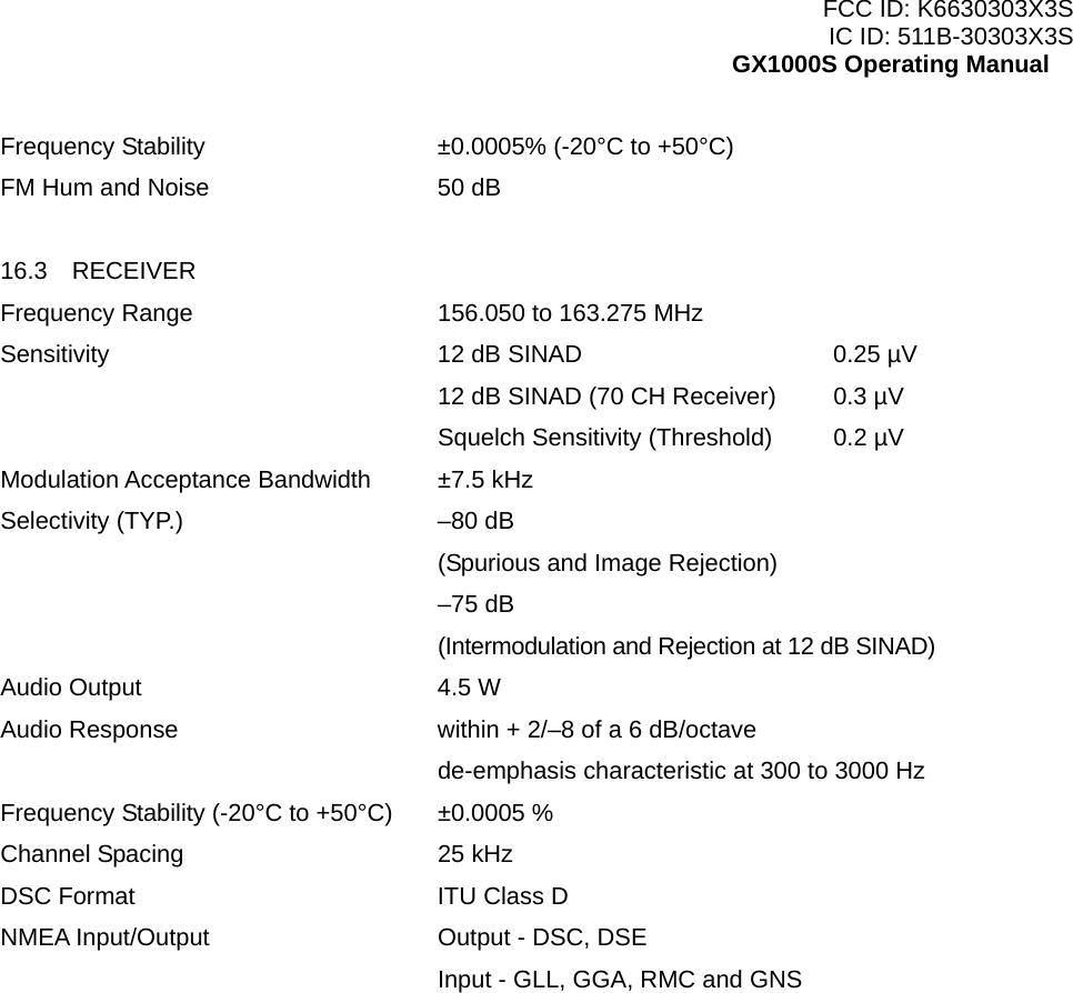
![FCC ID: K6630303X3S IC ID: 511B-30303X3S GX1000S Operating Manual 1 GENERAL INFORMATION The Vertex Standard GX1000S ECLIPSE DCS is a VHF/FM transceiver designed for use in the frequency range of 156.025 to 163.275 MHz. The GX1000S ECLIPSE DCS can be operated from 11 to 16 VDC and has a switchable RF output power of 1 watt or 25 watts. The GX1000S ECLIPSE DCS is capable of RTCM SC101 DSC (Digital Selective Calling) operation. The GX1000S ECLIPSE DCS operates on all currently-allocated marine channels which are switchable for use with either USA, International, or Canadian regulations. It has an emergency channel 16 which can be immediately selected from any channel by pressing the red [16/9] key. NOAA Weather channels can also be accessed immediately by pressing the [WX] key. Other features of the transceiver include: scanning, priority scanning, submersible mic, high and low voltage warning, and GPS repeatability. 2 PACKING LIST When the package containing the transceiver is first opened, please check it for the following contents: GX1000S ECLIPSE DCS Transceiver Mounting Bracket and attaching hardware Panel Cover Owner’s Manual Power Cord 3 OPTIONS MMB-84 Flush-Mount Bracket MLS-310 Amplified External Speaker MLS-300 External Loudspeaker 101W White External Speaker 4 SAFETY / WARNING INFORMATION This radio is restricted to occupational use, work related operations only where the radio operator must have the knowledge to control the exposure conditions of its passengers and bystanders by maintaining the minimum separation distance of 0.6 m (2 feet). Failure to observe these restrictions will result in exceeding the FCC RF exposure limits. Antenna Installation: The antenna must be located at least 0.6 m (2 feet) away from passengers in order to comply with the FCC RF exposure requirements. ON-LINE WARRANTY REGISTRATION Please visit www.standardhorizon.com to register the GX1000S Marine VHF. It should be noted that visiting the Web site from time to time may be beneficial to you, as new products are released they will appear on the Marine Division of Vertex Standard Web site. 5](https://usermanual.wiki/Yaesu-Musen/30303X3S/User-Guide-846091-Page-5.png)
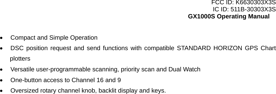
![FCC ID: K6630303X3S IC ID: 511B-30303X3S GX1000S Operating Manual 8.4 CHECKING GPS CONNECTIONS After connections have been made between the GX1000S and the GPS, a small satellite icon will appear on the LCD display. To see the additional GPS information, press and hold the [H/L] key. The GX1000S displays “LAT” and “LON” information alternately every two seconds. 8.5 CHANGING THE GPS TIME From the Factory the GX1000S shows GPS satellite time or UTC time. A time offset is needed to show the local time in your area. 1. Press and hold down the [CALL(SET)MENU] key until “RADIO SETUP” menu appears. 2. Press the [CALL(SET)MENU] key, then select “OFFSET TIME” with the [T]/[S] keys. 3. Press the [CALL(SET)MENU] key. 4. Press the [T]/[S] keys to select time offset from UTC. See illustration below to find your offset time from UTC. If “0:00” is assigned, the time is the same as UTC (Universal Time Coordinated or GMT Greenwich Mean Time). 5. Press the [CALL(SET)MENU] key to store the time offset. 6. Press the [16/9] key to exit the menu mode and return to radio operation. 8.6 CHANGING THE TIME LOCATION Sets the radio to show UTC time or local time with the offset inputted in section 8.6 Changing the GPS Time. 1. Press and hold down the [CALL(SET)MENU] key until “RADIO SETUP” menu appears. 2. Press the [CALL(SET)MENU] key, then select “TIME DISP” in the “Radio Setup” menu with the [T]/[S] keys. 3. Press the [CALL(SET)MENU] key. 4. Press the [T]/[S] keys to select “UTC” or “Local.” 5. Press the [CALL(SET)MENU] key to store the selected setting. 6. Press the [16/9] key to exit the menu mode and return to radio operation. In the local time mode, the display shows the time by the 12-hour system. Meanwhile, the display shows the time by the 24-hour system in the UTC mode. 8.7 OPTIONAL MMB-84 FLUSH MOUNT INSTALLATION 1. To assist in flush mounting, a template has been included. Use this template to find the mounting location. 2. Use the template to mark the location where the rectangular hole is to be cut. Confirm the space behind the dash or panel is deep enough to accommodate the transceiver (at least 6 inches or 10](https://usermanual.wiki/Yaesu-Musen/30303X3S/User-Guide-846091-Page-10.png)
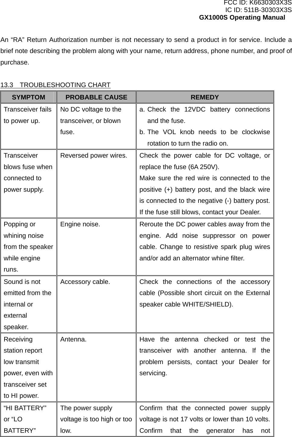
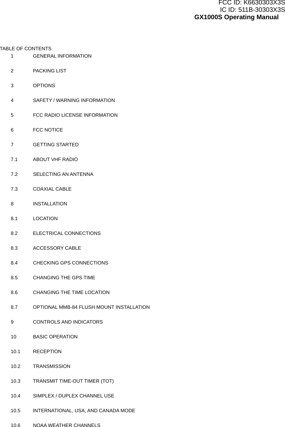
![FCC ID: K6630303X3S IC ID: 511B-30303X3S GX1000S Operating Manual 15 cm deep). There should be at least 1/2 inch (1.3 cm) between the transceiver’s heat sink and any wiring, cables or structures. 3. Cut out the rectangular hole and insert the transceiver. 4. Fasten the brackets to the sides of the transceiver with the lock washer nut combination; so that the mounting screw base faces the mounting surface (see Figure 2). 5. Turn the adjusting screw to adjust the tension so that the transceiver is tight against the mounting surface. 9 CONTROLS AND INDICATORS NOTE This section defines each control of the transceiver. See Figure 4 for location of controls. For detailed operating instructions refer to section “10 BASIC OPERATION.” 1. POWER SWITCH / VOLUME CONTROL (VOL) Turns the transceiver on and off as well as adjusts the audio volume. Turn this knob clockwise to turn the radio on and to increase the audio volume level. Turn fully counter-clockwise to turn the radio off. 2. SQUELCH CONTROL (SQL) Adjusting this control clockwise sets the point at which random noise on the channel does not activate the audio circuits but a received signal does. This point is called the squelch threshold. Further adjustment of the squelch control will degrade reception of wanted transmissions. 3. [H/L] Key Press this key to toggle the transmit output power between 25 W (High) and 1 W (Low) power. When the [H/L] key is pressed while the transceiver is on channel 13 or 67, the power will temporarily switch from LO to HI power until the PTT is released. The [H/L] key does not function on transmit inhibited and low power only channels. NOTE: 1W low power is indicated by LO on the display, when 25W high power is selected the display do not show an indication. Secondary use Press and hold this key, the LCD displays NAV GPS Time and vessel’s position (LAT/LON) when a GPS is connected to the accessory cable of the GX1000S. See section “8.4 CONNECTION OF GPS WITH NMEA OUTPUT” for details. 4. [WX] Key Immediately recalls the previously selected NOAA weather channel from any channel. Secondary use Holding down the [16/9] key while pressing the [WX] key changes from USA, International and 11](https://usermanual.wiki/Yaesu-Musen/30303X3S/User-Guide-846091-Page-11.png)
![FCC ID: K6630303X3S IC ID: 511B-30303X3S GX1000S Operating Manual Canadian channel groups. 5. [16/9] Key Immediately recalls channel 16 from any channel location. Holding down this key recalls channel 9. Pressing the [16/9] key again reverts to the previous selected working channel. Secondary use Press and hold the [16/9] key then press the [WX] key to switch the Channel Group. 6. KEYPAD [S(UP)]/[T(DOWN)] Keys The [S] and [T] keys are used to select a desired channel and to select items in the DSC OPERATION and SETUP menus. [SCAN(MEM)] Key Press this key to start and stop the scanning of programmed channels. Refer to section “10.12 SCANNING” for details. Secondary use To memorized a channel into scan memory, select the channel and press and hold the [SCAN(MEM)] key until “MEM” is shown on the display. To delete a memorized channel from scan memory, select the channel and press and hold the [SCAN(MEM)] key until “MEM” is removed from the display. [CALL(SET)MENU] Key Press the [CALL(SET)MENU] key to access the DSC OPERATION menu. The “INDIVIDUAL CALL,” “GROUP CALL,” and “ALL SHIPS CALL” functions can be accessed from the DSC OPERATION menu. NOTE: Before the DSC OPERATION menu can be selected a MMSI must be entered. Refer to section “11.2 MARITIME MOBILE SERVICE IDENTITY (MMSI).” Secondary use Press and hold the [CALL(SET)MENU] key to access the “Radio Setup” (refer to section “12 RADIO SETUP MODE”) or “DSC Setup” menu (refer to section “11 DIGITAL SELECTIVE CALLING”). 7. [DISTRESS] Key Used to send a DSC Distress Call. To send the distress call refer to section “11.3.1 (Transmitting A DSC Distress Call).” 8. DC INPUT CABLE Connects the radio to a DC power supply capable of delivering 12V DC. 9. EXTERNAL SPEAKER CONNECTION CABLE Connects the GX1000S to a external speaker. 10. GPS RECEIVER CONNECTION CABLE 12](https://usermanual.wiki/Yaesu-Musen/30303X3S/User-Guide-846091-Page-12.png)
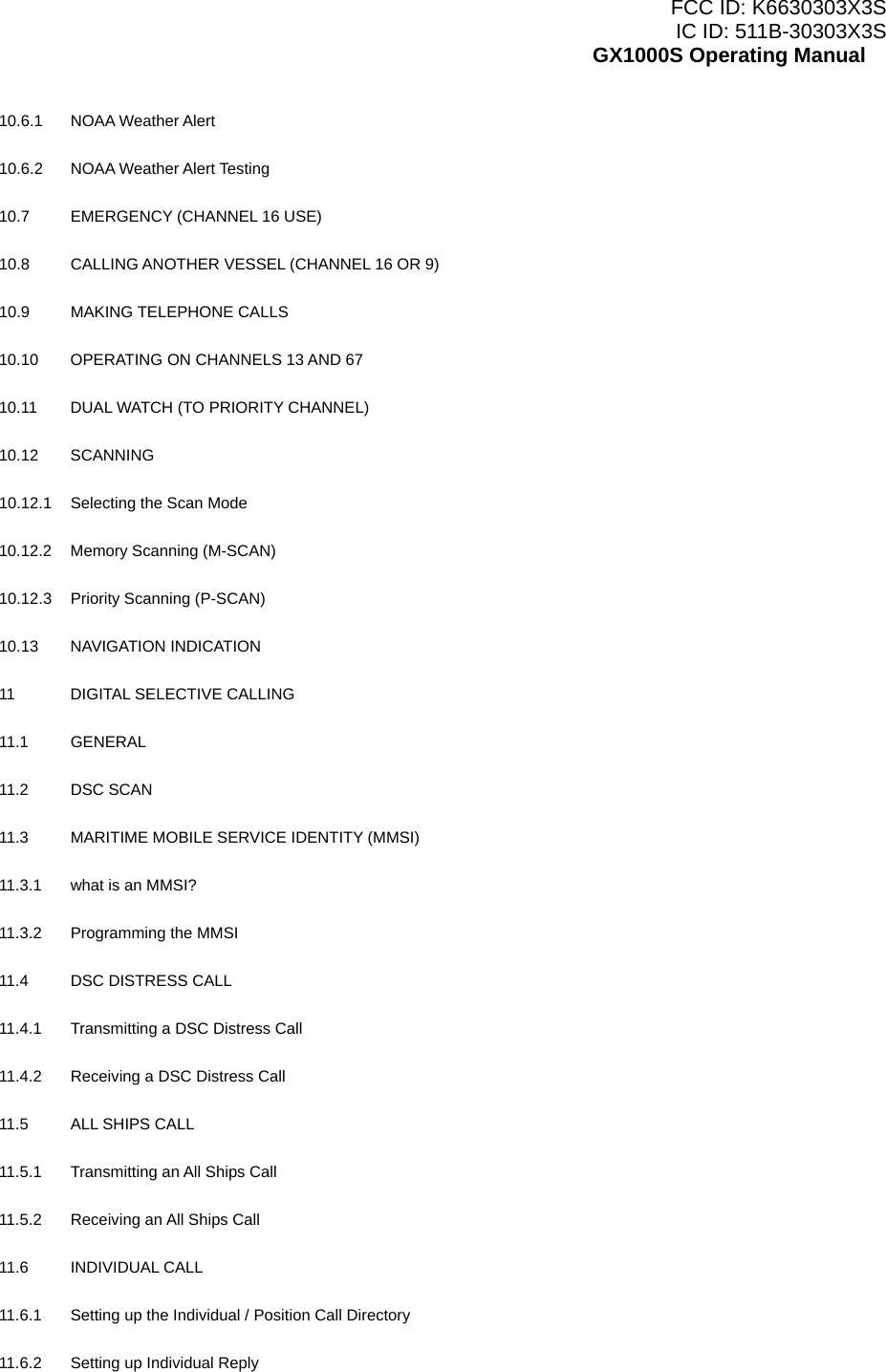
![FCC ID: K6630303X3S IC ID: 511B-30303X3S GX1000S Operating Manual Connects the GX1000S to a GPS receiver. 11. ANTENNA JACK Connects an antenna to the transceiver. Use a marine VHF antenna with an impedance of 50 ohms. 12. PTT (Push-To-Talk) SWITCH Keys the transmitter when the transceiver is in radio mode. 13. MICROPHONE Transmits the voice message with reduction of background noise, using Clear Voice Noise Reduction Technology. NOTE: Be sure your mouth is about 1/2 inch (1 cm) from the mic hole for best performance. 10 BASIC OPERATION 10.1 RECEPTION 1. After the transceiver has been installed, ensure that the power supply and antenna are properly connected. 2. Turn the VOL knob clockwise to turn on the radio. 3. Turn the SQL knob fully counterclockwise. This state is known as “squelch off”. 4. Turn up the VOL knob until noise or audio from the speaker is at a comfortable level. 5. Turn the SQL knob clockwise until the random noise disappears. This state is known as the “squelch threshold.” 6. Press the [S] or [T] key to select the desired channel. Refer to the channel chart on page 83 for available channels. 7. When a message is received, adjust the VOL knob to the desired listening level. The “BUSY” indicator in the LCD is displayed indicating that the channel is being used. 10.2 TRANSMISSION 1. Perform steps 1 through 6 of RECEPTION. 2. Before transmitting, monitor the channel to ensure it is clear. THIS IS AN FCC REQUIREMENT! 3. Press the PTT (push-to-talk) switch. The “TX” indicator in the LCD is displayed. 4. Speak slowly and clearly into the microphone. 5. When the transmission is finished, release the PTT switch. NOTE This is a noise-canceling microphone. The oval slot on the bottom of microphone should be positioned within 1/2 inch (1.3 cm) from the mouth for optimum performance. 13](https://usermanual.wiki/Yaesu-Musen/30303X3S/User-Guide-846091-Page-13.png)
![FCC ID: K6630303X3S IC ID: 511B-30303X3S GX1000S Operating Manual 10.3 TRANSMIT TIME - OUT TIMER (TOT) When the PTT switch on the microphone is held down, transmit time is limited to 5 minutes. This limits unintentional transmissions due to a stuck microphone. About 10 seconds before automatic transmitter shutdown, a warning beep will be heard from the speaker(s). The transceiver will automatically go to receive mode, even if the PTT switch is continually held down. Before transmitting again, the PTT switch must first be released and then pressed again. 10.4 SIMPLEX/DUPLEX CHANNEL USE Refer to the VHF MARINE CHANNEL CHART for instructions on use of simplex and duplex channels. NOTE All channels are factory-programmed in accordance with International, Industry Canada (Canada), and FCC (USA) regulations. Mode of operation cannot be altered from simplex to duplex or vice-versa. 10.5 INTERNATIONAL, USA, AND CANADA MODE 1. To change the modes, hold the [16/9] key and press the [WX] key. The mode changes from International to Canadian to USA with each press of the [WX] key. 2. “I” will be displayed for International mode, “C” will be displayed for Canadian mode, and “U” will be displayed on the LCD for USA mode. 3. Refer to the VHF MARINE CHANNEL CHART for allocated channels in each mode. 10.6 NOAA WEATHER CHANNELS NOTE NOAA Weather channels are available in the waters of USA and Canada only. 1. To receive a NOAA weather channel, press the [WX] key from any channel. The transceiver will go to the last selected weather channel. 2. Press the [S]/[T] keys to select a different NOAA weather channel. 3. To exit from the NOAA weather channels, press the [WX] key. The transceiver returns to the channel it was on prior to a weather channel. 10.6.1 NOAA Weather Alert In the event of extreme weather disturbances, such as storms and hurricanes, the NOAA (National Oceanic and Atmospheric Administration) sends a weather alert accompanied by a 1050 Hz tone and subsequent weather report on one of the NOAA weather channels. When the Weather Alert feature is enabled (see section “12.9 WX ALERT”), the transceiver is capable of receiving this alert if 14](https://usermanual.wiki/Yaesu-Musen/30303X3S/User-Guide-846091-Page-14.png)
![FCC ID: K6630303X3S IC ID: 511B-30303X3S GX1000S Operating Manual the following is performed: 1. Program NOAA weather channels into the transceiver’s memory for scanning. Follow the same procedure as for regular channels under section “10.12 SCANNING.” 2. Press the [SCAN(MEM)] key once to start memory scanning or priority scanning (determined from the “Radio Setup” selection, see page 56 for details). 3. The programmed NOAA weather channels will be scanned along with the regular-programmed channels. However, scanning will not stop on a normal weather broadcast unless a NOAA alert is received. 4. When an alert is received on a NOAA weather channel, scanning will stop and the transceiver will emit a loud beep to alert the user of a NOAA broadcast. 5. Press the [WX] key to stop the alert tone and receive the weather report. NOTE If the [WX] key is not pressed the alert tone will be emitted for 5 minutes and then the weather report will be received. NOTE The Weather Alert feature is also engaged while the transceiver is receiving on one of the NOAA weather channels. 10.6.2 NOAA Weather Alert Testing NOAA tests the alert system every Wednesday between 11AM and 1PM. To test the GX1000S’s NOAA Weather alert feature, on Wednesday between 11AM and 1PM, setup as in previous section and confirm the alert is heard. 10.7 EMERGENCY (CHANNEL 16 USE) Channel 16 is known as the Hail and Distress Channel. An emergency is defined as a threat to life or property. In such instances, be sure the transceiver is on and set to CHANNEL 16. Then use the following procedure: 1. Press the microphone push-to-talk switch and say “Mayday, Mayday, Mayday. This is , , ” (your vessel’s name). 2. Then repeat once: “Mayday, ” (your vessel’s name). 3. Now report your position in latitude/longitude, or by giving a true or magnetic bearing (state which) to a well-known landmark such as a navigation aid or geographic feature such as an island or harbor entry. 4. Explain the nature of your distress (sinking, collision, aground, fire, heart attack, life-threatening injury, etc.). 5. State the kind of assistance your desire (pumps, medical aid, etc.). 15](https://usermanual.wiki/Yaesu-Musen/30303X3S/User-Guide-846091-Page-15.png)
![FCC ID: K6630303X3S IC ID: 511B-30303X3S GX1000S Operating Manual To make a radiotelephone call, use a channel designated for this purpose, The fastest way to learn which channels are used for radiotelephone traffic is to ask at a local marina. Channels available for such traffic are designated Public Correspondence channels on the channel charts in this manual. Some examples for USA use are Channels 24, 25, 26, 27, 28, 84, 85, 86, and 87. Call the marine operator and identify yourself by your vessel’s name, The marine operator will then ask you how you will pay for the call (telephone credit card, collect, etc.) and then link your radio transmission to the telephone lines. The marine telephone company managing the VHF channel you are using may charge a link-up fee in addition to the cost of the call. 10.10 OPERATING ON CHANNELS 13 AND 67 Channel 13 is used at docks and bridges and by vessels maneuvering in port. Messages on this channel must concern navigation only, such as meeting and passing in restricted waters. Channel 67 is used for navigational traffic between vessels. By regulation, power is normally limited to 1 Watt on these channels. Your radio is programmed to automatically reduce power to this limit on these channels. However, in certain situations it may be necessary to temporarily use a higher power. See page 20 ([H/L(NAV)] key) for means to temporarily override the low-power limit on these two channels. 10.11 DUAL WATCH (TO PRIORITY CHANNEL) Dual watch allows the radio to monitor one channel and the assigned Priority channel. By default the priority channel is set to 16, however the priority channel may be changed by referring to section “12.6 PRIORITY CHANNEL SET.” 1. Adjust the SQL knob until the background noise disappears. 2. Select the channel you wish to dual watch to “Priority channel.” 3. Press the [DW(IC)] key. The display will scan between Priority channel and the channel that was selected in step 2. If a transmission is received on the channel selected in step 2, the GX1000S will dual watch between the working channel and the Priority channel. 4. To stop Dual Watch, press the [DW(IC)] key again. 10.12 SCANNING Allows the user to select the scan type from Memory scan or Priority scan. “Memory scan” scans the channels that were programmed into memory. “Priority scan” scans the channels programmed in memory with the priority channel. 17](https://usermanual.wiki/Yaesu-Musen/30303X3S/User-Guide-846091-Page-17.png)
![FCC ID: K6630303X3S IC ID: 511B-30303X3S GX1000S Operating Manual 10.12.1 Selecting the Scan Type 1. Press and hold down the [CALL(SET)MENU] key until “RADIO SETUP” menu appears. 2. Press the [CALL(SET)MENU] key, then select “SCAN” in the “RADIO SETUP” menu with the [T]/[S] keys. 3. Press the [CALL(SET)MENU] key. 4. Press the [T]/[S] keys to select “PSCAN (Priority scan)” or “MSCAN (Memory scan).” 5. Press the [CALL(SET)MENU] key to store the selected setting. 6. Press the [16/9] key to exit the menu mode and return to radio operation. 10.12.2 Memory Scanning (M-SCAN) 1. Adjust the SQL knob until background noise disappears. 2. Select a desired channel to be scanned using the [T]/[S] keys. Press and hold the [SCAN(MEM)] key for one second, “MEM” will appear on the LCD which indicates the channel has been programmed into the transceivers memory. 3. Repeat step 2 for all the desired channels to be scanned. 4. To DELETE a channel from the transceiver’s memory, select the channel then press and hold the [SCAN(MEM)] key for one second, “MEM” will disappear in the LCD. 5. To start scanning, just press the [SCAN(MEM)] key momentarily. “MSCAN” appears on the LCD. Scanning will proceed from the lowest to the highest programmed channel number and will stop on a channel when a transmission is received. 6. The channel number will blink during reception. 7. To stop scanning, press the [16/9] or [WX] key. 10.12.3 Priority Scanning (P-SCAN) In the default setting, Channel 16 is set as the priority channel. You may change the priority channel to the desired channel from the Channel 16 by the Radio Setup Mode, refer to section “12.6 PRIORITY CHANNEL SET.” 1. Adjust the SQL knob until background noise disappears. 2. Select a desired channel to be scanned using the [T]/[S] keys. Press and hold the [SCAN(MEM)] key for one second, “MEM” will appear on the display which indicates the channel has been programmed into the transceivers memory. 3. Repeat step 2 for all the desired channels to be scanned. 4. To DELETE a channel from the transceiver’s memory, select the channel then press and hold the [SCAN(MEM)] key until “MEM” is removed from the display. 5. To start priority scanning, just press the [SCAN(MEM)] key momentarily. “PSCAN” appears on the LCD. Scanning will proceed between the memorized channels, and the priority channel. The 18](https://usermanual.wiki/Yaesu-Musen/30303X3S/User-Guide-846091-Page-18.png)
![FCC ID: K6630303X3S IC ID: 511B-30303X3S GX1000S Operating Manual priority channel will be scanned after each programmed channel. 6. To stop scanning, press the [16/9] or [WX] key. 10.13 NAVIGATION INDICATION The transceiver has the ability to display Time and the position (LAT/LON), when connected to a GPS receiver. 1. Press and hold the [H/L] key, displays “LAT” and “LON” information alternately every two seconds. If the GPS receiver is not receiving a fix, the display will be as shown in the illustration on the right. NOTE: When Ch16 is selected only lat/lon will shown. 2. To hide the position information, press and hold the [H/L] key again. 11 DIGITAL SELECTIVE CALLING 11.1 GENERAL WARNING This radio is designed to generate a digital maritime distress and safety call to facilitate search and rescue. To be effective as a safety device, this equipment must be used only within communication range of a shore-based VHF marine channel 70 distress and safety watch system. The range of signal may vary but under normal conditions should be approximately 20 nautical miles. NOTE A DSC Warning sticker is included with the GX1000S. To comply with FCC regulations this sticker must be mounted in a location that can be easily viewed from the location of the GX1000S. Make sure the chosen location is clean and dry before applying the sticker. Digital Selective Calling is a semi-automated method of establishing a radio call, it has been designated by the International Maritime Organization (IMO) as an international standard for establishing VHF, MF, and HF radio calls. It has also been designated as part of the Global Maritime Distress and Safety System (GMDSS). It is planned that DSC will eventually replace aural watches on distress frequencies and will be used to announce routine and urgent maritime safety information broadcasts. This new system allows mariners to instantly send a distress call with GPS position (when connected to the transceiver) to the Coast Guard and other vessels within range of the transmission. DSC will also allow mariners to initiate or receive Distress, Urgency, Safety, Routine, POSITION REQUEST, POSITION SEND, and Group calls to or from another vessel equipped with a DSC transceiver. 11.2 DSC SCAN 19](https://usermanual.wiki/Yaesu-Musen/30303X3S/User-Guide-846091-Page-19.png)
![FCC ID: K6630303X3S IC ID: 511B-30303X3S GX1000S Operating Manual When the radio is shipped from the factory it is programmed so CH70 (the DSC channel) is scanned at all times. There is a selection in the SETUP MENU to disable the DSC SCAN. However, turning off DSC SCAN will disable the radio from receiving DSC calls i.e.: Individual Call, All Ships Call, Distress Call and Position Requests. If you want to use any of the functions the selection must be left ON. To Change DSC SCAN Method: 1. Press and hold down the [CALL(SET)MENU] key until “RADIO SETUP” menu appears. 2. Press the [T] key to select “DSC SETUP” menu. 3. Press the [CALL(SET)MENU] key, then select “DSC SCAN” with the [S]/[T] keys. 4. Press the [CALL(SET)MENU] key. 5. Press the [S]/[T] keys to select “on” or “oF (off).” 6. Press the [CALL(SET)MENU] key to store the selected setting. 7. Press the [16/9] key to exit the menu mode and return to radio operation. 11.3 MARITIME MOBILE SERVICE IDENTITY (MMSI) 11.3.1 What is an MMSI? An MMSI is a nine digits number used on Marine Transceivers capable of using Digital Selective Calling (DSC). This number is used like a telephone number to selectively call other vessels. THIS NUMBER MUST BE PROGRAMMED INTO THE RADIO TO OPERATE THE GX1000S DSC FUCTIONS. How can I obtain an MMSI assignment? Boat US offers online registration of a MMSI. Visit www.boatus.com/mmsi 11.3.2 Programming the MMSI WARNING User MMSI can be input only ONCE, please be careful not to input the incorrect MMSI number. If you try to enter the MMSI more than one time, the radio will show the display to the right. If the MMSI number has been entered incorrectly, the transceiver will have to be sent to Factory Service to be reset. Refer to the section “15.2. FACTORY SERVICE” for the address. When finished programming the MMSI number, press and hold the [CALL(SET)MENU] key until the confirmation message appears, then press the [CALL(SET)MENU] key to store the number in memory and return to radio operation mode. If the user needs to change the MMSI number after it has been entered, the radio will have to be returned to Factory Service. 1. Press and hold down the [CALL(SET)MENU] key until the “Radio Setup” menu appears. 2. Press the [T] key to select “DSC SETUP” menu. 20](https://usermanual.wiki/Yaesu-Musen/30303X3S/User-Guide-846091-Page-20.png)
![FCC ID: K6630303X3S IC ID: 511B-30303X3S GX1000S Operating Manual 3. Press the [CALL(SET)MENU] key, then select “USER MMSI” with the [S]/[T] keys. 4. Press the [CALL(SET)MENU] key. The display will show a series of dashes or the last MMSI number if programmed. 5. Press the [S]/[T] keys to select the first number of your MMSI, then press the [CALL(SET)MENU] key to step to the next number. 6. Repeat step 5 to set your MMSI (up to nine digits). 7. When finished programming the number, press and hold the [CALL(SET)MENU] key to show the display at the right. 8. Press the [CALL(SET)MENU] key to save the MMSI number into memory. 9. Press the [16/9] key to exit the menu mode and return to radio operation. 11.4 DSC DISTRESS CALL The GX1000S is capable of transmitting and receiving DSC Distress messages to all DSC radios. The GX1000S may be connected to a GPS to also transmit the Latitude, Longitude of the vessel. 11.3.1 Transmitting a DSC Distress Call NOTE To be able to transmit a DSC distress call an MMSI number must be programmed, refer to section “11.2.2 Programming the MMSI.” In order for your ships location to be transmitted a GPS must be connected to the GX1000S, refer to section “8.4 CONNECTION OF GPS WITH NMEA OUTPUT.” 1. Lift the red spring loaded DISTRESS cover and press the [DISTRESS] key. The “DISTRESS” menu will appear on the LCD. 2. Press and hold the [DISTRESS] key. The radios display will count down (5-4-3-2-1) and then transmit the Distress call. 3. When the distress signal is sent, CH70 and “TX” icon will appear on the LCD. After the message has been sent, the radio will sound a Distress Alarm and display will flash. 4. The transceiver will watch for a DSC acknowledgment transmission on CH70 and also receive calls on CH16. 5. If an acknowledgement is received, select channel 16 and advise your distress situation. 6. If no acknowledgment is received, the distress call is repeated in 4 minute intervals until a DSC acknowledgment is received. 7. When a DSC Distress acknowledgment is received, a distress alarm sounds and channel 16 is automatically selected. The LCD shows the MMSI of the ship responding to your distress. RECEIVED ACK: acknowledgment signal is received. RECEIVED RLY: relay signal is received from another vessel or coast station. 21](https://usermanual.wiki/Yaesu-Musen/30303X3S/User-Guide-846091-Page-21.png)
![FCC ID: K6630303X3S IC ID: 511B-30303X3S GX1000S Operating Manual 8. To cancel the DSC distress alarm signal from the speaker, press any key. Transmitting a DSC Distress Call with Nature of Distress The GX1000S is capable of transmitting a DSC Distress Call with the following “Nature of Distress” categories: Undesignated, Fire, Flooding, Collision, Grounding, Capsizing, Sinking, Adrift, Abandoning, Piracy, Mob 1. Lift the red spring loaded DISTRESS cover and press the [DISTRESS] key. The “DISTRESS” menu will appear on the LCD. 2. Press the [S]/[T] keys to select the desired nature of distress category. 3. Press and hold the [DISTRESS] key. The radios display will count down (5-4-3-2-1) and then transmit the Distress call. 4. When the distress signal is sent, CH70 and “TX” icon will appear on the LCD. After the message has been sent, the radio will sound a Distress Alarm and display will flash. 5. The transceiver will watch for a DSC acknowledgment transmission on CH70 and also receive calls on CH16. 6. If an acknowledgement is received, select channel 16 and advise your distress situation. 7. If no acknowledgment is received, the distress call is repeated in 4 minute intervals until a DSC acknowledgment is received. 8. When a DSC Distress acknowledgment is received, a distress alarm sounds and channel 16 is automatically selected. The LCD shows the MMSI of the ship responding to your distress. RECEIVED ACK: acknowledgment signal is received. RECEIVED RLY: relay signal is received from another vessel or coast station. 9. To cancel the DSC distress alarm signal from the speaker, press any key. Cancel a DSC Distress Call If a DSC Distress call was sent by error the GX1000S allows you to send a message to other vessels to cancel the Distress Call that was made in error. 1. Press the [CALL(SET)MENU] key. The “DSC Operation” menu will appear. 2. Press the [S]/[T] keys to select “CANCEL.” 3. Press the [CALL(SET)MENU] key to transmit the Distress Cancel Call. 11.4.2 Receiving a DSC Distress Call 1. When a DSC Distress call is received, an emergency alarm sounds. Then channel 16 is automatically selected. 2. Press any key to stop the alarm. 22](https://usermanual.wiki/Yaesu-Musen/30303X3S/User-Guide-846091-Page-22.png)
![FCC ID: K6630303X3S IC ID: 511B-30303X3S GX1000S Operating Manual 3. Press the [S]/[T] keys to change the display to show the position of the vessel in distress. 4. If the position of the vessel distress data does not include position, the LCD will show the display on the right. NOTE You must continue monitoring channel 16 as a coast station may require assistance in the rescue attempt. 11.5 ALL SHIPS CALL The All Ships Call function allows contact to be established with other vessel stations without having their ID in the individual calling directory. Also, priority for the call can be designated as Urgency or Safety. URGENCY Call: This type of call is used when a vessel may not truly be in distress, but have a potential problem that may lead to a distress situation. This call is the same as saying PAN PAN PAN on channel 16. SAFETY Call: Used to transmit boating safety information to other vessels. This message usually contains information about an overdue boat, debris in the water, loss of a navigation aid or an important meteorological message. This call is the same as saying Securite, Securite, Securite.” 11.5.1 Transmitting an All Ships Call 1. Press the [CALL(SET)MENU] key. The “DSC Operation” menu will appear. 2. Press the [S]/[T] keys to select “ALL SHIPS.” 3. Press the [CALL(SET)MENU] key. (To cancel, press the [S]/[T] keys to select “EXIT.”) 4. Press the [S]/[T] keys to select the call (“URGENT,” “SAFETY,” or “ROUTINE”). 5. Press the [CALL(SET)MENU] key to transmit the selected type of all ships DSC call. 6. After the ALL SHIPS CALL is transmitted, the transceiver will switch to CH16. 7. Listen to the channel to make sure it is not busy, then key the microphone and say PAN PAN PAN or “Securite, Securite, Securite” depending on the priority of the call. Say your call sign and announce the channel you wish to switch to for communications. 11.5.2 Receiving an All Ships Call 1. When an all ships call is received, an emergency alarm sounds. The radio will automatically change to channel 16. 2. Press any key to stop the alarm. 3. Press the [CALL(SET)MENU] key to see the MMSI of the vessel transmitting the All Ships Call. 4. Monitor channel 16 or traffic channel until the URGENCY voice communication is completed. 23](https://usermanual.wiki/Yaesu-Musen/30303X3S/User-Guide-846091-Page-23.png)
![FCC ID: K6630303X3S IC ID: 511B-30303X3S GX1000S Operating Manual 11.6 INDIVIDUAL CALL This feature allows the GX1000S to contact another vessel with a DSC VHF radio and automatically switch the receiving radio to a desired communications channel. This feature is similar to calling a vessel on CH16 and requesting to go to another channel (switching to the channel is private between the two stations). 11.6.1 Setting up the Individual / Position Call Directory The GX1000S has a DSC directory that allows you to store a vessel or person’s name and the MMSI number associated with vessels you wish to transmit Individual calls, Position Requests and Position Send transmissions. To transmit an Individual call you must program this directory with information of the persons you wish to call, similar to a cellular phones telephone directory. 1. Press and hold down the [CALL(SET)MENU] key until “RADIO SETUP” menu appears. 2. Press the [T] key to select “DSC SETUP” menu. 3. Press the [CALL(SET)MENU] key, then select “INDIV DIR” with the [S]/[T] keys. 4. Press the [CALL(SET)MENU] key, then select “ADD” with the [S]/[T] keys. 5. Press the [CALL(SET)MENU] key. 6. Press the [S]/[T] keys to scroll through the first letter of the name of the vessel or person you want to reference in the directory. 7. Press the [CALL(SET)MENU] key to store the first letter in the name and step to the next letter to the right. 8. Repeat step 6 and 7 until the name is complete. The name can consist of up to eleven characters, if you do not use all eleven characters press the [CALL(SET)MENU] key to move to the next space. This method can also be used to enter a blank space in the name. To clear the previous letter, press the [SCAN(MEM)] key. 9. After the eleventh letter or space has been entered, press and hold the [CALL(SET)MENU] key to advance to the MMSI Maritime Mobile Service Identity Number entry. 10. Press the [S]/[T] keys to scroll through numbers, 0-9. To enter the desired number and move one space to the right press the [CALL(SET)MENU] key. Repeat this procedure until all nine space of the MMSI number are entered. 11. If a mistake was made entering in the name or the MMSI number repeat pressing the [SCAN(MEM)] key until the wrong character is selected, then move the channel knob to correct the entry. 12. To store the data entered, press and hold the [CALL(SET)MENU] key. 13. To enter another individual address, repeat steps 4 through 12. 24](https://usermanual.wiki/Yaesu-Musen/30303X3S/User-Guide-846091-Page-24.png)
![FCC ID: K6630303X3S IC ID: 511B-30303X3S GX1000S Operating Manual 14. Press the [16/9] key to exit the menu mode and return to radio operation. 11.6.2 Setting up Individual Reply Allows setting up the radio to automatically (default setting) or manually respond to a DSC Individual call requesting you to switch to a working channel for voice communications. When Manual is selected the MMSI of the calling vessel is shown allowing you to see who is calling. This function is similar to caller id on a cellular phone. 1. Press and hold down the [CALL(SET)MENU] key until “RADIO SETUP” menu appears. 2. Press the [T] key to select “DSC SETUP” menu. 3. Press the [CALL(SET)MENU] key, then select “INDIVIDUAL REPLY” with the [S]/[T] keys. 4. Press the [ENT]key. 5. Press the [S]/[T] keys to select “Au (automatically)” or “oF (oFF).” 6. Press the [CALL(SET)MENU] key to store the selected setting. 7. Press the [16/9] key to exit the menu mode and return to radio operation. 11.6.3 Setting up the Individual / Group Call Ringer When an Individual Call or Group Call is received the radio will produce a ringing tone for 2 minutes. This selection allows the Individual Call ringer time to be changed. 1. Press and hold down the [CALL(SET)MENU] key until “RADIO SETUP” menu appear. 2. Press the [T] key to select “DSC SETUP” menu. 3. Press the [CALL(SET)MENU] key, then select “INDIVIDUAL RINGER” with the [S]/[T] keys. 4. Press the [CALL(SET)MENU] key. 5. Press the [S]/[T] keys to select ringing time of a Individual Call. 4: 2 minutes 3: 15 times 2: 10 times 1: 5 times 6. Press the [CALL(SET)MENU] key to store the selected setting. 7. Press the [16/9] key to exit the menu mode and return to radio operation. 11.6.4 Transmitting an Individual Call This feature allows the user to contact another vessel with a DSC radio. This feature is similar to calling a vessel on CH16 and requesting to go to another channel. 1. Press the [CALL(SET)MENU] key. The “DSC Operation” menu will appear. 2. Press the [S]/[T] keys to select “INDIVIDUAL.” (To cancel, select “EXIT” with the [S]/[T] keys.) 3. Press the [CALL(SET)MENU] key. The transceiver will beep, and the “Individual directory” will 25](https://usermanual.wiki/Yaesu-Musen/30303X3S/User-Guide-846091-Page-25.png)
![FCC ID: K6630303X3S IC ID: 511B-30303X3S GX1000S Operating Manual appear. 4. Press the [S]/[T] keys to select the “Individual” you want to contact. 5. Press the [CALL(SET)MENU] key, then press the [S]/[T] keys to select the operating channel you want to communicate on and press the [CALL(SET)MENU] key. 6. Press the [CALL(SET)MENU] key again to transmit the individual DSC signal. 7. After INDIVIDUAL CALL is transmitted, the transceiver will wait 8 seconds for the acknowledgment. If the reply signal is not received, the transceiver will transmit again. 8. After the second INDIVIDUAL CALL is transmitted, if the reply signal is not received, the display will be as shown in the illustration on the right. To send the call again, press the [ENT] key. 9. When an individual call acknowledgment is received, the established channel is automatically changed to the channel which is selected on step 5 above and a ringing tone sounds. 10. Press any key to listen to the channel to make sure it is not busy, then key the microphone and call the other vessel you desire to communicate with. 11.6.5 Receiving an Individual Call When receiving an individual call, an acknowledgment must be sent back to the calling station. The GX1000S default setting is Automatic, but has a selection that allows you to manually send a reply before the radio will switch to the requested calling channel. This selection is useful if you want to see who is calling and requesting you to switch to a channel for communications, similar to caller id on a cellular phone. 1. When an individual call is received, an individual call ringing alarm sounds. The radio automatically switches to the requested channel. 2. Press any key to stop the alarm. 3. Press the PTT on the mic and talk to the calling ship. 11.6.6 Setting Up the Call Waiting Function Allows the GX1000S to be setup to reply (ABLE) or set the radio so it transmits a call that advises the calling vessel the person is UNABLE to reply to the call at this time. This function is similar to an answering machine. When set up in UNABLE and a individual call is received the Individual call from the other vessel is logged in the CALL WAITING directory for you to review and call back at a later time. 1. Press and hold down the [CALL(SET)MENU] key until “RADIO SETUP” menu appears. 2. Press the [T] key to select “DSC SETUP” menu. 3. Press the [CALL(SET)MENU] key, then select “INDIVIDUAL ACK” with the [S]/[T] keys. 4. Press the [CALL(SET)MENU] key. 5. Press the [S]/[T] keys to select “Ab (Able)” or “Un (Unable).” 26](https://usermanual.wiki/Yaesu-Musen/30303X3S/User-Guide-846091-Page-26.png)
![FCC ID: K6630303X3S IC ID: 511B-30303X3S GX1000S Operating Manual 6. Press the [CALL(SET)MENU] key to store the selected setting. 7. Press the [16/9] key to exit the menu mode and return to radio operation. 11.7 POSITION REQUEST Advancements in DSC have made it possible to poll the location of another vessel and show the position of that vessel on the display of the GX1000S. Standard Horizon has taken this feature one step further, if any Standard Horizon GPS is connected to the GX1000S, the polled position of the vessel is shown on the display of the GPS chart plotter making it easy to navigate to the location of the polled vessel. This is a great feature for anyone wanting to know the position of another vessel. For example your buddy that is catching fish, or finding the location of a person you are cruising with. NOTE The other vessel must have an operating GPS receiver connected to its DSC transceiver and must not have its transceiver set to deny position requests. (Refer the section “11.5.1 Setting up the Individual / Position Call Directory” to enter information into the individual directory). 11.7.1 Setting up Position Reply The GX1000S can be set up to automatically or manually send your position to another vessel. This selection is important if you are concerned about someone polling the position of your vessel that you may not want to. In the manual mode you will see the MMSI or persons name shown on the display allowing you to choose to send your position to the requesting vessel. 1. Press and hold down the [CALL(SET)MENU] key until “RADIO SETUP” menu appears. 2. Press the [T] key to select “DSC SETUP” menu. 3. Press the [CALL(SET)MENU] key, then select “POS REQUEST REPLY” with the [S]/[T] keys. 4. Press the [CALL(SET)MENU] key. 5. Press the [S]/[T] keys to select “AU (Auto)” or “oF (off: Manual).” In “AU (Auto)” mode, after a DSC POS Request is received, the radio will automatically transmit your vessels position. In “oF (off: Manual)” mode, the display of the GX1000S will show who is requesting the position. 6. Press the [CALL(SET)MENU] key to store the selected setting. 7. Press the [16/9] key to exit the menu mode and return to radio operation. 11.7.2 Transmitting a Position Request to Another Vessel 1. Press the [CALL(SET)MENU] key. The “DSC Operation” menu will appear in the display. 2. Press the [S]/[T] keys to select “POS REQUEST.” 3. Press [CALL(SET)MENU] key to show the Position request directory. This directory uses the INDIVIDUAL Directory information. 27](https://usermanual.wiki/Yaesu-Musen/30303X3S/User-Guide-846091-Page-27.png)
![FCC ID: K6630303X3S IC ID: 511B-30303X3S GX1000S Operating Manual 4. Press the [S]/[T] keys to select a name, then press the [CALL(SET)MENU] key. 5. Press the [CALL(SET)MENU] key to transmit the position request DSC call. 6. When the GX1000S receives the position from the polled vessel it is shown on the radio display and also transferred to the GPS Chart plotter. 7. If the GX1000S does not receive a reply, the display will be as shown in the illustration on the right. To send again, press the [CALL(SET)MENU] key. NOTE If the GX1000S does not receive position data from the polled vessel, the LCD will show “NO POSITION DATA.” 11.7.3 Receiving a Position Request When a position request call is received from another vessel, a ringing alarm will sound and POS REQUEST will be shown in the LCD. Operation and transceiver function differs depending on “POS REPLY” in the “DSC SETUP” menu setting. Automatically reply: 1. When a position request call is received, a calling alarm sounds 4 times. Then requested position coordinates are transmitted automatically to the vessel requesting your vessels position. 2. To exit from position request display, press any key. Manually reply: 1. When a position request call is received from another vessel, the LCD will be as shown in the illustration at the right. 2. A ringing alarm sounds 4 times. Then select type of reply function “SEND” or “NO REPLY” by using the [S]/[T] keys. 3. The GX1000S display will show “SEND” or “NO REPLY” allowing you to send your vessels location by using the [S]/[T] keys. 4. When “SEND” is selected, press the [CALL(SET)MENU] key. And your position will be transmitted to the requesting vessel. 5. Press the [16/9] key to exit from position request display. 11.8 POSITION SEND The feature is similar to Position Request, however instead of requesting a position of another vessel this function allows you to send your position to another vessel. Your vessel must have an operating GPS receiver connected for the GX1000S to send the position. 28](https://usermanual.wiki/Yaesu-Musen/30303X3S/User-Guide-846091-Page-28.png)
![FCC ID: K6630303X3S IC ID: 511B-30303X3S GX1000S Operating Manual 11.8.1 Transmitting a DSC Position Send Call 1. Press the [CALL(SET)MENU] key. The “DSC Operation” menu will appear in the display. 2. Turn the [S]/[T] keys to select the “POS Send.” 3. Press the [CALL(SET)MENU] key to select the Individual directory. 4. Press the [S]/[T] keys to select a name in the directory, then press the [CALL(SET)MENU] key. 5. Press the [CALL(SET)MENU] key to send your position to the selected vessel. 11.8.3 Receiving a DSC Position Send Call When another vessel transmits their location to the GX1000S the following will happen: 1. A ringing sound will be produced when the call is received. 2. Press the [16/9] key to stop ringing 3. The position from the calling vessel will be shown on the display of the radio and also transferred to any Standard Horizon GPS Chart plotter if connected. 12 RADIO SETUP 12.1 LAMP ADJUSTING Allows setting up the backlight intensity or to turn it off. 1. Press and hold down the [CALL(SET)MENU] key until “RADIO SETUP” menu appears. 2. Press the [CALL(SET)MENU] key, then select “DIMMER” in the “RADIO SETUP” menu with the [S]/[T] keys. 3. Press the [CALL(SET)MENU] key. 4. Press the [S]/[T] keys to select the desired level. The dimmer level can be set from “0” to “7.” When “0” is selected, the lamp is extinguished. 5. Press the [CALL(SET)MENU] key to store the selected level. 6. Press the [16/9] key to exit the menu mode and return to radio operation. 12.2 LCD CONTRAST This selection sets up the display for best viewabilty for the varying mounting locations (overhead or below). 1. Press and hold down the [CALL(SET)MENU] key until “RADIO SETUP” menu appears. 2. Press the [CALL(SET)MENU] key, then select “CONTRUST” in the “RADIO SETUP” menu with the [S]/[T] keys. 3. Press the [CALL(SET)MENU] key. 4. Press the [S]/[T] keys to select the desired level. The contrast level can be set from “0” to “7.” 5. Press the [CALL(SET)MENU] key to store the selected level. 6. Press the [16/9] key to exit the menu mode and return to radio operation. 29](https://usermanual.wiki/Yaesu-Musen/30303X3S/User-Guide-846091-Page-29.png)
![FCC ID: K6630303X3S IC ID: 511B-30303X3S GX1000S Operating Manual 12.3 SCAN TYPE This selection selects the scan mode between “Memory Scan” and “Priority Scan.” 1. Press and hold down the [CALL(SET)MENU] key until “RADIO SETUP” menu appears. 2. Press the [CALL(SET)MENU] key, then select “SCAN” in the “RADIO SETUP” menu with the [S]/[T] keys. 3. Press the [CALL(SET)MENU] key. 4. Press the [S]/[T] keys to select “MSCAN (Memory Scan)” or “PSCAN (Priority Scan).” 5. Press the [CALL(SET)MENU] key to store the selected setting. 6. Press the [16/9] key to exit the menu mode and return to radio operation. 12.4 TIME OFFSET This selection sets the time offset between local time and UTC (time GPS sends to radio). Time is displayed when GPS position (LAT/LON) is displayed by press and holding the [H/L] key. 1. Press and hold down the [CALL(SET)MENU] key until “RADIO SETUP” menu appears. 2. Press the [CALL(SET)MENU] key, then select “OFFSET TIME” in the “RADIO SETUP” menu with the [S]/[T] keys. 3. Press the [CALL(SET)MENU] key. 4. Press the [S]/[T] keys to select time offset from UTC. See illustration below to find your offset time from UTC. If “0:00” is assigned, the time is the same as UTC (Universal Time Coordinated or GMT Greenwich Mean Time). 5. Press the [CALL(SET)MENU] key to store the time offset. 6. Press the [16/9] key to exit the menu mode and return to radio operation. 12.5 TIME LOCATION This selection selects the time display between local time and UTC (time GPS sends to radio). Time is displayed when GPS position (LAT/LON) is displayed by press and holding the [H/L] key. 1. Press and hold down the [CALL(SET)MENU] key until “RADIO SETUP” menu appears. 2. Press the [CALL(SET)MENU] key, then select “TIME DISP” in the “RADIO SETUP” menu with the [S]/[T] keys. 3. Press the [CALL(SET)MENU] key. 4. Press the [S]/[T] keys to select “UTC” or “LOCAL.” 5. Press the [CALL(SET)MENU] key to store the selected setting. 6. Press the [16/9] key to exit the menu mode and return to radio operation. In the local time mode, the display shows the time by the 12-hour system. Meanwhile, the display shows the time by the 24-hour system in the UTC mode. 30](https://usermanual.wiki/Yaesu-Musen/30303X3S/User-Guide-846091-Page-30.png)
![FCC ID: K6630303X3S IC ID: 511B-30303X3S GX1000S Operating Manual 12.6 PRIORITY CHANNEL SET Allows selection of the priority channel. 1. Press and hold down the [CALL(SET)MENU] key until “RADIO SETUP” menu appears. 2. Press the [CALL(SET)MENU] key, then select “PRI-CH” in the “RADIO SETUP” menu with the [S]/[T] keys. 3. Press the [CALL(SET)MENU] key. 4. Press the [S]/[T] keys to select the channel to be a priority. 5. Press the [CALL(SET)MENU] key to store the selected setting. 6. Press the [16/9] key to exit the menu mode and return to radio operation. 12.7 KEY BEEP (ON/OFF) This selection allows the beep tone when a key is pressed to be turned off. 1. Press and hold down the [CALL(SET)MENU] key until “RADIO SETUP” menu appears. 2. Press the [CALL(SET)MENU] key, then select “KEY BEEP” in the “RADIO SETUP” menu with the [S]/[T] keys. 3. Press the [CALL(SET)MENU] key. 4. Press the [S]/[T] keys to select “ON” or “OFF.” 5. Press the [CALL(SET)MENU] key to set the key beep condition. 6. Press the [16/9] key to exit the menu mode and return to radio operation. NOTE Emergency alarm and beeps for DSC operation cannot be turned OFF. 12.8 WX ALERT This selection allows the radios NOAA Weather alert to be turned off. Default setting is ON. 1. Press and hold down the [CALL(SET)MENU] key until “RADIO SETUP” menu appears. 2. Press the [CALL(SET)MENU] key, then select “WX ALERT” in the “RADIO SETUP” menu with the [S]/[T] keys. 3. Press the [CALL(SET)MENU] key. 4. Press the [S]/[T] keys to select the desired WX alert mode. The WX alert mode can be set to “ON WX,” “ON SCAN,” “ON SCAN/WX,” or “OFF.” 5. Press the [CALL(SET)MENU] key to store the selected setting. 6. Press the [16/9] key to exit the menu mode and return to radio operation. 13 MAINTENANCE The inherent quality of the solid-state components used in this transceiver will provide many years of 31](https://usermanual.wiki/Yaesu-Musen/30303X3S/User-Guide-846091-Page-31.png)