Yaesu Musen 30313X30 HANDHELD VHF TRANSCEIVER User Manual HX850 Operating Manual
Yaesu Musen Co., Ltd. HANDHELD VHF TRANSCEIVER HX850 Operating Manual
UserManual.wiki
>
Yaesu Musen
>
30313X30 User Manual
USERS MANUAL
Navigation menu
Upload a User Manual
Namespaces
Wiki Guide
HTML
PDF
Info
Views
User Manual
Discussion / Help
Navigation
![FCC ID:K6630313X30 IC ID:511B-30313X30 Operating Manual Vertex Standard Co.,Ltd. 3Unauthorized changes or modifications to this equipment may void compliance with FCC Rules. Any change or modification must be approved in writing by STANDARD HORIZON, a Marine Division of VERTEX STANDARD. NOTICE This equipment has been tested and found to comply with the limits for a Class B digital device, pursuant to Part 15 of the FCC Rules. These limits are designed to provide reasonable protection against harmful interference in a residential installation. This equipment generates uses and can radiate radio frequency energy and, if not installed and used in accordance with the instructions, may cause harmful interference to radio communications. However, there is no guarantee that interference will not occur in a particular installation. If this equipment does cause harmful interference to radio or television reception, which can be determined by turning the equipment off and on, the user is encouraged to try to correct the interference by one or more of the following measures: Increase the separation between the equipment and receiver. Connect the equipment into an outlet on a circuit different from that to which the receiver is connected. Consult the dealer or an experienced marine electronics technician for help. 1. GENERAL INFORMATION 1.1 INTRODUCTION The HX850S is a SUBMERSIBLE miniature 6-Watt portable two way marine transceiver. The transceiver has all allocated USA, International, or Canadian channels. It has emergency channel 16 which can be immediately selected from any channel by pressing the [16/9] key. NOAA Weather channels can also be accessed immediately by pressing the [WX] key. The HX850S includes the following features: Memory Scanning, Priority Scanning, NOAA Weather Alert, Battery Saver, easy-to-read large LCD display, EEPROM memory back-up, Battery Life displayed on LCD, and a transmit Time-Out Timer (TOT). In the marine band, the transmitter provides a maximum of 6 Watts output, and has the selection of 5 Watts, 2.5 Watts, and 1 Watt to assist the user in ensuring maximum battery life. 2. ACCESSORIES 2.1 PACKING LIST When the package containing the transceiver is first opened, please check it for the following contents: HX850S Transceiver FNB-V99LI 7.4 V, 1150 mAh LI-ion Battery Pack CD-38 Charger Cradle for HX850S NC-88B 120VAC Wall Charger for CD-38 E-DC-19A DC Cable with 12 V Cigarette Lighter Plug for CD-38](https://usermanual.wiki/Yaesu-Musen/30313X30/User-Guide-898126-Page-3.png)
![FCC ID:K6630313X30 IC ID:511B-30313X30 Operating Manual Vertex Standard Co.,Ltd. 7 NOTE The CD-38 is only designed for the charging of the HX850S’s battery, and is not suitable for other purposes. The CD-38 may contribute noise to TV and radio reception in the immediate vicinity, so we do not recommend its use adjacent to such device. 4.2 CONNECTING A CHART PLOTTER TO THE CD-38 The CD-38 is supplied with a cable which is designed to connect the NMEA output with the GGL, GGA, GSA, GSV, or RMC sentences of the HX850 to any GPS and chart plotter. The NMEA output cable on the CD-38 contains two wires, uses are shown below: Brown: NMEA output- Connect to NMEA input of chart plotter Blue: NMEA input - Connect to NMEA output of GPS Green: NMEA Negative If you have further inquires, please feel free to contact Product Support at: Phone: (800) 767-2450 Email: marinetech@vxstdusa.com To connect the chart plotter, connect the wires between the CD-38 and the GPS and chart plotter. Insure that the wires are properly shielded from water. 5. CONTROLS AND INDICATORS NOTE This section defines each control of the transceiver. For detailed operating instructions, refer to section 6 “BASIC OPERATION.” Refer to illustrations for the location of the following controls, switches, and connections. MIC/SP JACK The jack accepts the optional CMP460 Speaker/Microphone, MH-57A4B Mini Speaker/Microphone, or VC-24 VOX Headset. When this jack is used, the internal speaker is disabled. PUSH-TO-TALK (PTT) SWITCH When pushed activates the transmitter of the selected band. DISTRESS Key This used to send a DSC Distress Call. To send the distress call, refer to section “Transmitting a DSC Distress Call”. [VOL] KEY Press this key to activate the volume adjusting mode. Press the [T] or [S] key to adjust the receiver audio volume level.](https://usermanual.wiki/Yaesu-Musen/30313X30/User-Guide-898126-Page-7.png)
![FCC ID:K6630313X30 IC ID:511B-30313X30 Operating Manual Vertex Standard Co.,Ltd. 8 [S(UP)] KEY This key is used to increment the operating channel, receiver volume level, and squelch threshold level. Press the key momentarily, the channel (or level) increases one step. Holding the key, the channel (or level) increases continuously. [T(DOWN)] KEY This key is used to decrement the operating channel, receiver volume level, and squelch threshold level. Press the key momentarily, the channel (or level) decreases one step. Holding the key, the channel (or level) decreases continuously. [SQL] KEY Press this key to activate the squelch adjusting mode. Press the [T] or [S] key to adjust the squelch threshold level. Press and hold this key for 3 seconds to open the squelch, allowing you to monitor the operating channel. Release the key to resume normal (quiet) monitoring. [WX] KEY Immediately recalls the last-used NOAA Weather Channel from any channel location. Recalls the previously- selected working channel when the [WX] key is pressed again. Secondary use: When the [16/9] key is held and the [WX] key is pressed, the radio will change the marine channel between the USA, International, and Canadian channels. [SCAN(DW)] KEY Starts scanning and priority scanning of programmed channels. When scanning, press and hold this key to turn on and off priority scan (“P” icon is shown on the bottom left side of the display during Priority scanning). [H/L(LOCK)] KEY Press this key to toggle the transmitter output power between “Normal” (6 Watts), “High” (5 Watts), “Medium” (2.5 Watts), and “Low” (1 Watt) power. This key does not function on the “Transmission Inhibited” and “Low power only” channels. Secondary use:](https://usermanual.wiki/Yaesu-Musen/30313X30/User-Guide-898126-Page-8.png)
![FCC ID:K6630313X30 IC ID:511B-30313X30 Operating Manual Vertex Standard Co.,Ltd. 9Hold down this key to lock the keypad (except the PTT, [VOL], [SQL], [POWER], and [H/L(LOCK)] keys) so that they are not accidentally changed. The “KEY” icon will appear at the bottom right corner on the display, to indicate that the functions are locked. Hold down this key until the “KEY” icon disappears to unlock the radio. [16/9] KEY Press this key immediately recalls channel 16 from any channel location. Holding down this key recalls channel 9. Pressing this key again reverts to the previous selected working channel. [CLR(MEM)] KEY Press this key to cancel a selection the DSC Call Menu, Radio Setup, DSC Setup, or GPS Setup menus. Secondary use: Press and hold this key to memorize the selected channel for scanning. When pressed a “MEM” icon will be shown on the LCD display indicating the channel has been saved to scan memory. To delete the channel from scan memory, select the channel and press and hold this key until “MEM” is removed from the display. [POWER] KEY Press and hold this key for two seconds to toggle the transceiver’s power on and off. [CALL(MENU)SET] KEY Press this key to access the DSC Call Menu. The “Individual Call”, “Group Call”, “All Ships Call”, “Position Request”, “Position Report, “DSC Log”, and “DSC Test” functions can be accessed from the DSC Call Menu. Secondary use: Press and hold this key to access the “Radio Setup”, “DSC Setup” or “GPS Setup” menu. BUSY/TX INDICATOR This indicator glows green when a signal is being received and red when transmitting. When the Emergency feature is activated, this indicator blinks the internationally-recognized Morse Code “S.O.S” message. NMEA TERMINALS Connect this NMEA input/output terminal to the GPS or Chart Plotter via the CD-38 Charger Cradle. Keep these terminals clean.](https://usermanual.wiki/Yaesu-Musen/30313X30/User-Guide-898126-Page-9.png)
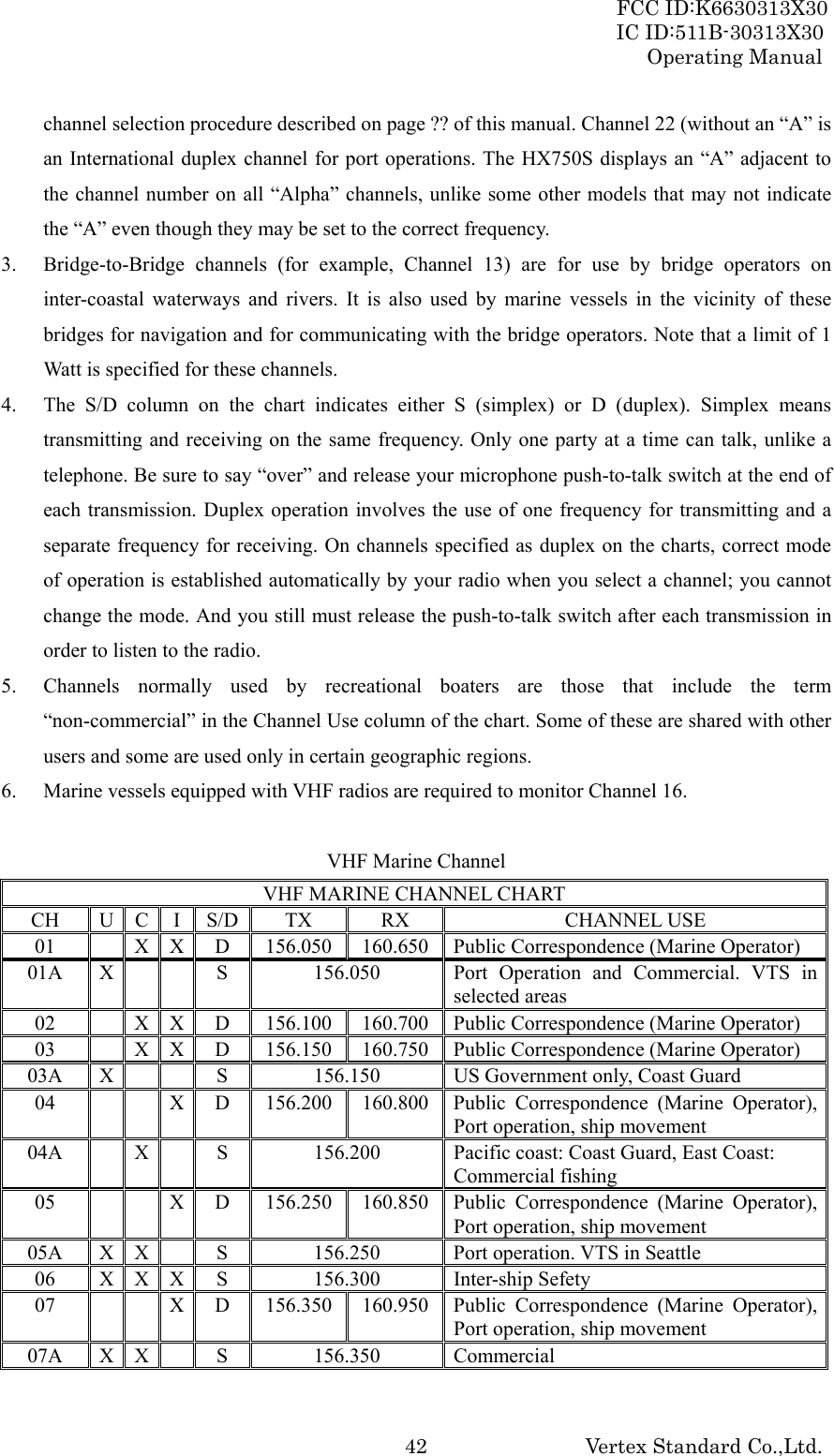
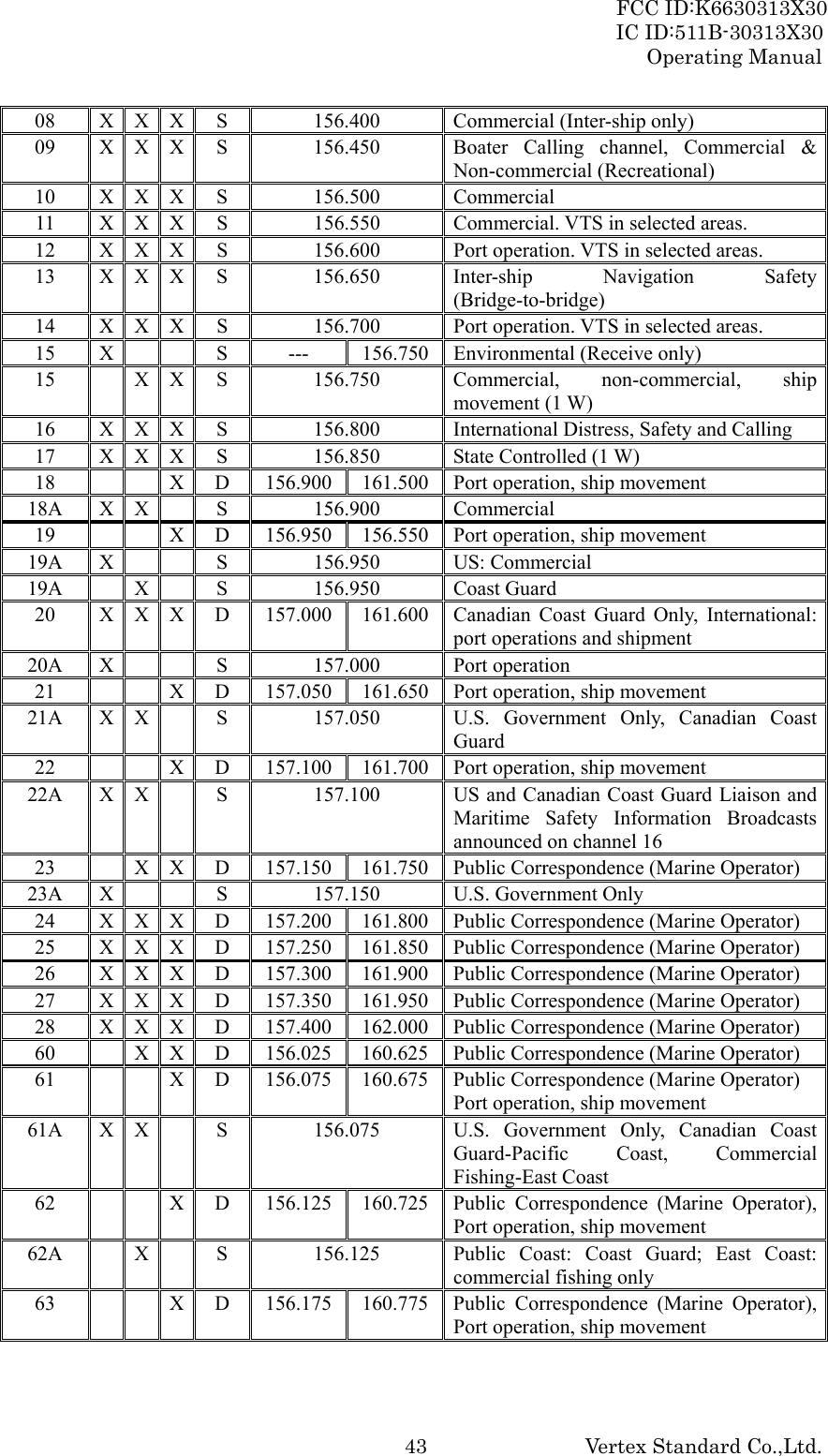
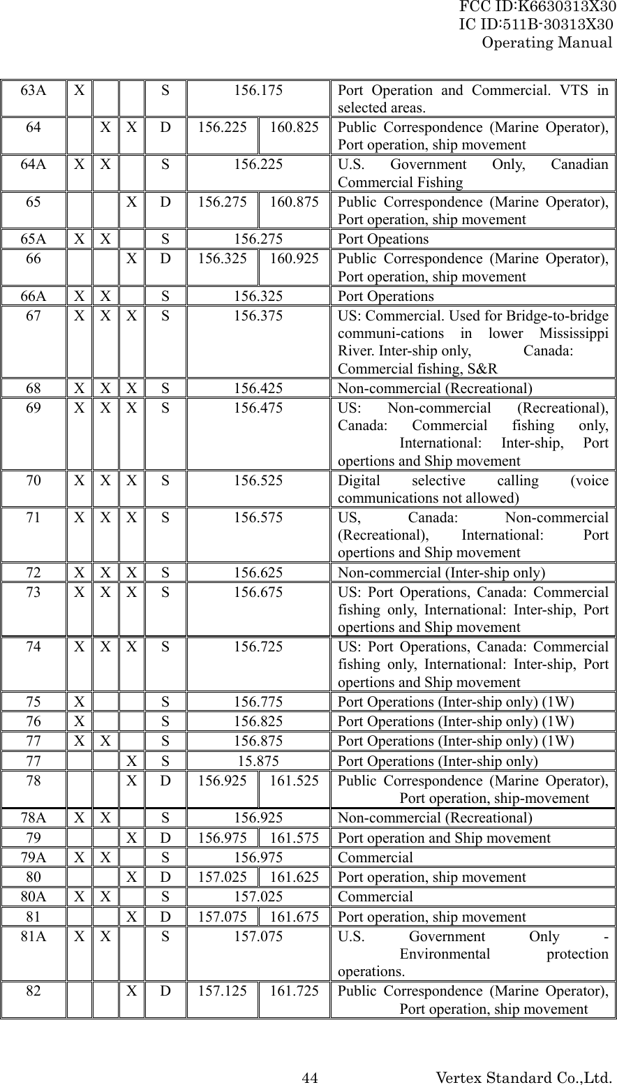
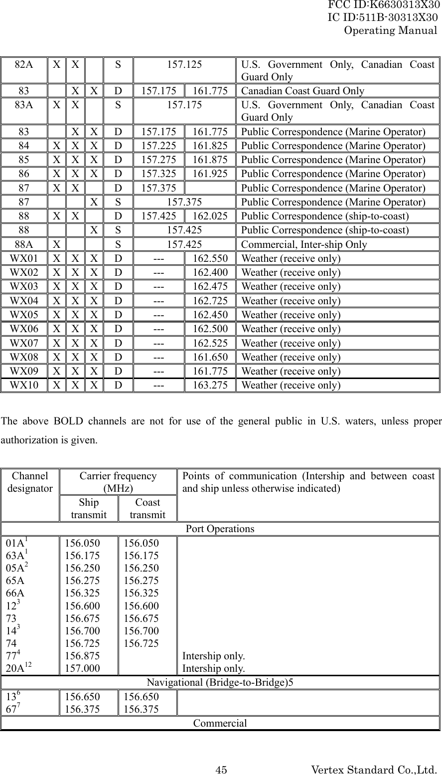
![FCC ID:K6630313X30 IC ID:511B-30313X30 Operating Manual Vertex Standard Co.,Ltd. 10 6. BASIC OPERATION 6.1 PROHIBITED COMMUNICATIONS The FCC prohibits the following communications: ・ False distress or emergency messages: ・ Messages to “any boat” except in emergencies and radio tests; ・ Messages to or from a vessel on land; ・ Transmission while on land; ・ Obscene, indecent, or profane language (potential fine of $10,000). 6.2 INITIAL SETUP 1. Install the belt clip on the transceiver according to the description in the box below, if desired. 2. Install the nylon carrying strap on the belt clip, if desired. 3. Install the battery pack on the transceiver (see section 4.1.3 “BATTERY INSTALLATION/REMOVAL”). NOTE: Water resistance of the transceiver is assured only when the battery pack is attached to the transceiver and MIC/SP rubber cap is installed in the MIC/SP jack. 6.3 RECEPTION 1. Press and hold the [POWER] key for two seconds to turn the transceiver on. 2. Press the [SQL] key, then press the [T] key until the SQL level is “00”. This state is known as “Squelch Off”. 3. Press the [VOL] key, then press the [T]/[S] key until the noise or audio from the speaker is at a comfortable level. 4. Press the [T] or [S] key to select a channel that has no signal being received (no one is transmitting on the channel). 5. Press the [SQL] key, then press the [S] key until the random noise is disappeared. This state is known as the “Squelch Threshold”. 6. Press the [T] or [S] key to select the desired channel. Refer to the channel chart on page ?? for available channels. 7. When a message is received, adjust the volume (Press the [VOL] key, followed by the [T]/[S] key) to desired listening level. The TX/BUSY indicator illuminates green indicating that the channel is being used. 6.4 TRANSMISSION](https://usermanual.wiki/Yaesu-Musen/30313X30/User-Guide-898126-Page-10.png)
![FCC ID:K6630313X30 IC ID:511B-30313X30 Operating Manual Vertex Standard Co.,Ltd. 111. Perform steps 1 through 7 of the “6.3 RECEPTION” discussion above. 2. Before transmitting, monitor the channel and make sure it is clear. THIS IS AN FCC REQUIREMENT! 3. For communications over short distances, press the [H/L(LOCK)] key until “L” is displayed on the LCD. This indicates Low power (approximately 1 watt). Note: Transmitting on 1 watt prolongs battery life. Low power (1 watt) should be selected whenever possible. 4. If using Low power is not effective, select Medium power (2.5 watts: “M” icon appears), High power (5 watts: “H” icon appears), or Normal power (6 watts: No icon) by pressing the [H/L(LOCK)] key. 5. When receiving a signal, wait until the incoming signal stops before transmitting. The transceiver cannot transmit and receive simultaneously. 6. Press the PTT (Push-To-Talk) switch to transmit. During transmission, the “TX” indicator will appear on the display and the TX/BUSY indicator will grow red. 7. Speak slowly and clearly into the microphone. Hold the microphone about 1 inch (2.5 cm) away from your mouth. 8. When the transmission is finished, release the PTT switch. 6.4.1 TRANSMIT TIME - OUT TIMER (TOT) While the PTT switch is held down, transmission time is limited to 5 minutes. This prevents prolonged (unintentional) transmissions. About 10 seconds before automatic transmitter shutdown, a warning beep sounds from the speaker. The transceiver automatically switches to the receiving mode, even if the PTT switch is held down. Before transmitting again, the PTT switch must first be released, and then pressed again. This Time-Out-Timer (TOT) prevents a continuous transmission that would result from an accidentally stuck PTT switch. 6.5 USA, CANADIAN, AND INTERNATIONAL CHANNELS 1. To change from US to Canadian or International Marine Channels, hold down the [16/9] key and press the [WX] key. The band will change from USA, to International, and to Canadian with each press. 2. “USA” appears on the LCD for the USA band, “CAN” appears for the Canadian band, and “INTL” appears for the International band. 3. Refer to the marine channel charts in section 16 “VHF MARINE CHANNEL ASSIGNMENTS” for allocated channels. 6.6 SIMPLEX/DUPLEX CHANNEL USE](https://usermanual.wiki/Yaesu-Musen/30313X30/User-Guide-898126-Page-11.png)
![FCC ID:K6630313X30 IC ID:511B-30313X30 Operating Manual Vertex Standard Co.,Ltd. 12Refer to the VHF MARINE CHANNEL CHART (page 42) for instructions on use of simplex and duplex channels. NOTE All channels are factory-programmed in accordance with FCC (USA), Industry Canada and International regulations. The mode of operation cannot be altered from simplex to duplex or vice-versa. Simplex (ship to ship) or duplex (marine operator) mode is automatically activated, depending on the channel and whether the USA, International or Canadian operating band is selected. 6.7 NOAA WEATHER CHANNELS 1. To receive a NOAA weather broadcast, press the [WX] key. The transceiver changes to the weather channel mode. This mode consists of a special preset memory bank containing the NOAA weather channels. 2. The transceiver will be set to the last used NOAA weather channel. Press the [T] or [S] key to change to other weather channels. 3. To exit from the weather channel mode, press the [WX] key. The transceiver will revert to the channel you were using prior to switching to the weather channel mode. 6.7.1 NOAA WEATHER ALERT In the event of extreme weather disturbances such as storms and hurricanes, NOAA (National Oceanic and Atmospheric Administration) sends a “weather alert” consisting of a 1050 Hz tone, followed by weather reports on the weather channels. The transceiver is capable of receiving this alert if the following is performed: 1. Program your area’s weather channels into the transceiver’s scan memory. Follow the same procedure as for regular channels. 2. Press the [SCAN(DW)] key to start the scan. 3. The memorized weather channels are scanned along with the regular memorized channels. Scanning will not stop on the (continuous) weather broadcast channels unless the weather alert tone is received. 4. When an alert is received on a weather channel, scanning stops and the transceiver emits a beeping tone that will stay on for 5 minutes. 5. Press the [WX] key to listen to the Weather Alert. 6.7.2 NOAA WEATHER ALERT TESTING In the event of a major storm or other appreciable weather condition requiring vessels at sea (or other bodies of water) to be notified, the NOAA (National Oceanographic and Atmospheric Administration) broadcasts a 1050 Hz tone that some VHF radios, including your HX750S, can detect for “Weather Alarm” purposes (refer to section 6.7.1 “NOAA WEATHER ALERT” for a](https://usermanual.wiki/Yaesu-Musen/30313X30/User-Guide-898126-Page-12.png)
![FCC ID:K6630313X30 IC ID:511B-30313X30 Operating Manual Vertex Standard Co.,Ltd. 13discussion of how to use this feature). The 1050 Hz tone, when detected, will produce a loud beep in the speaker of the HX850S, to signal that a Weather Alert Broadcast is being received. In order to test this system, NOAA broadcasts the 1050 Hz tone every Wednesday sometime between 11 AM and 1 PM local time. You may use this opportunity to test your HX850S periodically to confirm that the Weather Alert feature is working, or for training crew members on how to configure the HX850S to receive the NOAA Weather Alerts. 6.8 SCANNING The HX850S allows the user to select the scan type from “memory Scan” or “Priority Scan”. The “Memory Scan” scans the channels that were programmed into memory. The “Priority Scan” scans the channels programmed in memory with the user selected priority channel. 6.8.1 SELECTING THE SCAN TYPE 1. Press and hold the [CALL(MENU)ENT] key until the “Setup Menu” appears. 2. Press the [CALL(MENU)ENT] key, then select “SCAN Type” in the “Radio Setup” menu with the [T] / [S] key. 3. Press the [CALL(MENU)ENT] key, then select the desired Scan Type (““Memory Scan” or “Priority Scan”) with the [T] / [S] key. 4. Press the [CALL(MENU)ENT] key to store the selected setting. 5. Press the [16/9] key to exit the “Radio Setup” menu and return to radio operation mode. 6.8.2 MEMORY SCANNING (M-SCAN) The “Memory Scan” scans the channels that were programmed into memory. The HX850S can be programmed to scan channels from a minimum of 2 channels up to all channels in the marine band. If an incoming signal is detected on one of the channels during scan, the radio will pause on that channel, allowing you to listen to the incoming transmission. 1. Select the desired channel to be included in the scan memory using the [T] or [S] key. 2. Press and hold the [CLR(MEM)] key until “MEM” icon is shown on the display, thus the current channel is stored into the transceiver’s scan memory. 3. Repeat steps 1 and 2 for all the channels to be scanned. 4. To delete a channel from the transceiver’s scan memory, select the memorized channel, then press and hold the [CLR(MEM)] key until “MEM” is removed from the display. 5. All channels programmed remain in the transceiver’s scan memory even if the power is turned off. 6. Adjust the SQL level until background noise is eliminated by pressing the [SQL] key followed by the [T] / [S] key.](https://usermanual.wiki/Yaesu-Musen/30313X30/User-Guide-898126-Page-13.png)
![FCC ID:K6630313X30 IC ID:511B-30313X30 Operating Manual Vertex Standard Co.,Ltd. 147. To start scanning, press the [SCAN(DW)] key. The scan proceeds from the lowest to the highest programmed channel and stops scanning when a transmission is received. Scanning will resume when the incoming signal disappears at the end of the transmission. A “M-SCAN” icon will appears at the upper left of the display during scanning. 8. To stop the scan, press the [SCAN(DW)] key. 6.8.3 PRIORTY SCANNING (P-SCAN) The “Priority Scan” allows the radio to “Memory Scan” while also keeping watch on a particularly important “Priority Channel”. In the default setting, Channel 16 is set as the priority channel. You may change the priority channel to the desire channel from the Channel 16 by the “Radio Setup” menu. Setting Up the Priority Channel 1. Press and hold the [CALL(MENU)ENT] key until the “Setup Menu” appears. 2. Press the [CALL(MENU)ENT] key, then select “Priority CH” in the “Radio Setup” menu with the [T] / [S] key. 3. Press the [CALL(MENU)ENT] key, then select the desired channel to be a priority with the [T] / [S] key. 4. Press the [CALL(MENU)ENT] key to store the selected setting. 5. Press the [16/9] key to exit the “Radio Setup” menu and return to radio operation mode. A “P-CH” icon will appears at the upper left of the display when the priority channel is recalled. Operation 1. Select the desired channel to be included in the scan memory using the [T] or [S] key. 2. Press and hold the [CLR(MEM)] key until “MEM” icon is shown on the display, thus the current channel is stored into the transceiver’s scan memory. 3. Repeat steps 1 and 2 for all the channels to be scanned. 4. To delete a channel from the transceiver’s scan memory, select the memorized channel, then press and hold the [CLR(MEM)] key until “MEM” is removed from the display. 5. All channels programmed remain in the transceiver’s scan memory even if the power is turned off. 6. Adjust the SQL level until background noise is eliminated by pressing the [SQL] key followed by the [T] / [S] key. 7. To start scanning, press the [SCAN(DW)] key. The scan proceeds from the lowest to the highest programmed channel and stops scanning when a transmission is received. Scanning will resume when the incoming signal disappears at the end of the transmission. A “P-SCAN” icon will](https://usermanual.wiki/Yaesu-Musen/30313X30/User-Guide-898126-Page-14.png)
![FCC ID:K6630313X30 IC ID:511B-30313X30 Operating Manual Vertex Standard Co.,Ltd. 15appears at the upper left of the display during scanning. As an example of priority scanning, let us say that marine channels “06”, “07”, and “08” are memorized in the transceiver’s scan memory. Priority scanning will proceed in the following sequence: [CH06] Æ [Priority Channel] Æ [CH07] Æ [Priority Channel] Æ [CH08] Æ [Priority Channel] Æ [CH06] Æ [Priority Channel] ………… 8. Even when the transceiver stops and listens to the signal of a memorized channel, the transceiver will shift to a “Dual Watch” mode between this channel and the priority channel. Therefore, your priority watching of the designated channel is not compromised when the scanner has paused on an active channel. 9. To stop the scan, press the [SCAN(DW)] key. 6.9 DUAL WATCH The Dual Watch feature allows the radio watch the particularly important “Priority Channel” (determined section “6.10 PRIORITY SCAN”) while receiving the current channel. 1. Select the desired channel using the [T] or [S] key. 2. Hold down the [SCAN(DW)] key for two seconds, then release the key to activate the Dual Watch feature. A “TW-xx*” icon will appear on the upper left of the display when the Dual Watch feature is activated. *: Priority channel number. 3. When a transmission is received on the “Priority Channel”, the radio receives the “Priority Channel” until the incoming signal disappears. 4. The Dual Watch feature will resume when the incoming signal disappears at the end of the transmission. 5. Press the [SCAN(DW)] key to stop the Dual Watch feature and return to normal operation. 6.10 EMERGENCY (CHANNEL 16 USE) Channel 16 is known as the Hail and Distress Channel. An emergency may be defined as a threat to life or property. In such instances, be sure the transceiver is on and set to CHANNEL 16. Then use the following procedure: 1. Press the microphone push-to-talk switch and say “Mayday, Mayday, Mayday. This is _____, _____, _____” (your vessel’s name). 2. Then repeat once: “Mayday, _____” (your vessel’s name). 3. Now report your position in latitude/longitude, or by giving a true or magnetic bearing (state which) to a well-known landmark such as a navigation aid or geographic feature such as an island or harbor entry.](https://usermanual.wiki/Yaesu-Musen/30313X30/User-Guide-898126-Page-15.png)
![FCC ID:K6630313X30 IC ID:511B-30313X30 Operating Manual Vertex Standard Co.,Ltd. 17monitor Channel 16 even when set to other channels or when scanning. 6.12 OPERATING ON CHANNEL 13 Channel 13 is used at docks, bridges and for maneuvering in port. Messages on this channel must concern navigation only, such as meeting and passing in restricted waters. In emergencies and when approaching blind river bends, High power is allowed. Pressing the [H/L(KEY)] key will change the power output from Low Power (1 Watt) to Medium (2.5 Watts), High (5 Watts), or Normal (6 Watts) power will be selected. When you select to this channel again, the transceiver will revert to Low power. 6.13 OPERATING ON CHANNEL 67 When channel 67 is used for navigational bridge-to-bridge traffic between ships, Normal, High or Medium power may be used temporarily (in the USA band) by pressing the [H/L(KEY)] key. When you select to this channel again, the transceiver will revert to low power. 6.14 ENABLING S.O.S STROBE OPERATION The S.O.S. STROBE feature utilizes the high-intensity strobe LED on the front of the HX850S as a visual distress beacon. When enabled, the LED blinks the internationally-recognized Morse Code “S.O.S.” message (...---...) at a rate of 5 words per minute. This can be very useful in summoning help from rescuers who may not be able to communicate with you via radio. 1. Hold down the [MEM] key while turning the radio on to activate the emergency S.O.S. Strobe. Once the radio comes on, the BUSY/TX LED will flash the Morse Code S.O.S. message repeatedly. 2. The S.O.S. strobe function is interrupted when a signal is received or if the squelch control is turned so audio is heard from the speaker and during transmission. 3. To disable the S.O.S. strobe function, turn the radio off and back on again. 7. DIGITAL SELECTIVE CALLING 7.1 GENERAL WARNING This radio is designed to generate a digital maritime distress and safety call to facilitate search and rescue. To be effective as a safety device, this equipment must be used only within communication range of a shore-based VHF marine channel 70 distress and safety watch system. The range of signal may vary but under normal conditions should be approximately 20 nautical miles. Digital Selective Calling is a semi-automated method of establishing a radio call, it has been designated by the International Maritime Organization (IMO) as an international standard for](https://usermanual.wiki/Yaesu-Musen/30313X30/User-Guide-898126-Page-17.png)
![FCC ID:K6630313X30 IC ID:511B-30313X30 Operating Manual Vertex Standard Co.,Ltd. 18establishing VHF, MF and HF radio calls. It has also been designated as part of the Global Maritime Distress and Safety System (GMDSS). It is planned that DSC will eventually replace aural watches on distress frequencies and will be used to announce routine and urgent maritime safety information broadcasts. This new system allows mariners to instantly send a distress call with GPS position (when connected to the transceiver) to the US Coast Guard and other vessels within range of the transmission. DSC will also allow mariners to initiate or receive Distress, Urgency, Safety, Routine, POSITION REQUEST, POSITION SEND, and Group calls to or from another vessel equipped with a DSC transceiver. 7.2 MARITIME MOBILE SERVICE IDENTITY (MMSI) 7.2.1 WHAT IS AN MMSI? An MMSI is a nine digit number used on Marine Transceivers capable of using Digital Selective Calling (DSC). This number is used like a telephone number to selectively call other vessels. THIS NUMBER MUST BE PROGRAMMED INTO THE RADIO TO OPERATE THE HX850S DSC FUCTIONS. How can I obtain an MMSI assignment? Boat US offers free MMSI numbers. Visit the following to register: http://www.boatus.com/mmsi/ or www.seatow.com/boatingsafety/mmsiinfo.htm. 7.2.2 PROGRAMMING THE MMSI WARNING A user MMSI can be inputted only once. Therefore please be careful not to input the incorrect MMSI number. If the user needs to change the MMSI number after it has been entered, the radio will have to be returned to Factory Service. Refer to the section “FACTORY SERVICE”. 1. Press and hold down the [CALL(MEMU)ENT] key until the “Setup Menu” appears. 2. Press the [T] key to select “DSC Setup” menu. 3. Press the [CALL(MEMU)ENT] key, then select “User MMSI” with the [T] key. 4. Press the [CALL(MEMU)ENT] key. 5. Press the [T] / [S] key to select the first number of your MMSI, then press the [CALL(MEMU)ENT] key to step to the next number. 6. Repeat step 5 to set your MMSI (nine digits). 7. If a mistake was made entering, repeat pressing the [H/L(LOCK)] key until the wrong number selected, then press the [T] / [S] key to correct entry. 8. When finished programming the number, press and hold the [CALL(MEMU)ENT] key.](https://usermanual.wiki/Yaesu-Musen/30313X30/User-Guide-898126-Page-18.png)
![FCC ID:K6630313X30 IC ID:511B-30313X30 Operating Manual Vertex Standard Co.,Ltd. 19Appears the confirmation message on the display. Set your MMSI number again, then press and hold the [CALL(MEMU)ENT] key. 9. Press the [CALL(MEMU)ENT] key to store the MMSI number in memory. 10. Press the [CLR(MEM)] key twice to return to radio operation. 7.3 DSC DISTRESS ALERT The HX850S is capable of transmitting and receiving DSC Distress messages to all DSC radios. The HX850S also transmit the Latitude and Longitude of the vessel when the internal GPS unit is activating. 7.3.1 TRANSMITTING A DSC DISTRESS ALERT NOTE To be able to transmit a DSC Distress Call an MMSI number must be programmed, refer to section “7.2.2 PROGRAMMING THE MMSI”. In order for your ships location to be transmitted an internal GPS unit must be activated, refer to section “.3 ENABLING THE GPS RECEIVER”. 1. Lift the red DISTRESS rubber cover on the right side of the transceiver and press the [DISTRESS] key. The “DISTRESS ALERT” menu will appear on the display. 2. Press and hold the [DISTRESS] key. The radios display will count down (3-2-1), and afterwards the HX850S will transmit the DSC Distress Alert on channel 70. The backlight of the display and keypad flashes while the radios display is countdown. When the Distress signal is being sent, “TX” icon will appear on the display. 3. The transceiver “shadow-watches” for a transmission between Channel and Channel 70 until an acknowledgment signal is received. The display will be shown in the illustration on the right. 4. If an acknowledgement is received, select channel 16 and advise your distress situation. 5. If no acknowledgment is received, the distress call is repeated in 4 minute intervals until an acknowledgment is received. 6. When a DSC Distress acknowledgment is received, a distress alarm sounds and channel 16 is automatically selected. The display shows the MMSI of the ship responding to your distress. RECEIVED ACK: acknowledgment signal is received. RECEIVED RLY: relay signal is received from another vessel or coast station. 7. To cancel the DSC distress alarm signal from the speaker, press any key. Transmitting a DSC Distress Alert with Nature of Distress The HX850S is capable of transmitting a DSC Distress Alert with the following “Nature of Distress” categories: Undesignated, Fire, Flooding, Collision, Grounding, Capsizing, Sinking, Adrift, Abandoning, Piracy, and MOB.](https://usermanual.wiki/Yaesu-Musen/30313X30/User-Guide-898126-Page-19.png)
![FCC ID:K6630313X30 IC ID:511B-30313X30 Operating Manual Vertex Standard Co.,Ltd. 201. Lift the red DISTRESS rubber cover on the right side of the transceiver and press the [DISTRESS] key. The “DISTRESS ALERT” menu will appear on the display. 2. Press the [T] / [S] key to select the desired “Nature of Distress” category. 3. Press and hold the [DISTRESS] key. The radios display will count down (3-2-1), and afterwards the HX850S will transmit the DSC Distress Alert on channel 70. The backlight of the display and keypad flashes while the radios display is countdown. When the Distress signal is being sent, “TX” icon will appear on the display. 4. The transceiver “shadow-watches” for a transmission between Channel and Channel 70 until an acknowledgment signal is received. The display will be shown in the illustration on the right. 5. If an acknowledgement is received, select channel 16 and advise your distress situation. 6. If no acknowledgment is received, the distress call is repeated in 4 minute intervals until an acknowledgment is received. 7. When a DSC Distress acknowledgment is received, a distress alarm sounds and channel 16 is automatically selected. The display shows the MMSI of the ship responding to your distress. RECEIVED ACK: acknowledgment signal is received. RECEIVED RLY: relay signal is received from another vessel or coast station. 8. To cancel the DSC distress alarm signal from the speaker, press any key. Cancel a DSC Distress Alert If a DSC Distress Alert was sent by error the HX850S allows you to send a message to other vessels to cancel the Distress Alert that was made in error. Press the [CLR(MEM)] key, then press the [CALL(MENU)ENT] key. 7.3.2 RECEIVING A DSC DISTRESS ALERT 1. When a DSC Distress Alert is received, an emergency alarm sounds. Then channel 16 is automatically selected. 2. Press any key to stop the alarm. 3. Press the [CALL(MENU)ENT] key, the display shows the position of the vessel in distress. 4. If the position of the vessel distress data does not include position, the display will show the display on the right. NOTE You must continue monitoring channel 16 as a coast station may require assistance in the rescue attempt. 7.4 ALL SHIPS CALL The All Ships Call function allows contact to be established with other vessel stations without having their ID in the individual calling directory. Also, priority for the call can be designated as](https://usermanual.wiki/Yaesu-Musen/30313X30/User-Guide-898126-Page-20.png)
![FCC ID:K6630313X30 IC ID:511B-30313X30 Operating Manual Vertex Standard Co.,Ltd. 21Urgency or Safety. URGENCY Call: This type of call is used when a vessel may not truly be in distress, but have a potential problem that may lead to a distress situation. This call is the same as saying PAN PAN PAN on channel 16. SAFETY Call: Used to transmit boating safety information to other vessels. This message usually contains information about an overdue boat, debris in the water, loss of a navigation aid or an important meteorological message. This call is the same as saying Securite, Securite, Securite. 7.4.1 TRANSMITTING AN ALL SHIPS CALL 1. Press the [CALL(MENU)ENT] key. The “DSC Call Menu” will appear. 2. Press the [T] key to select “All Ships”. 3. Press the [CALL(MENU)ENT] key. (To cancel, press the [CLR(MEM)] key.) 4. Press the [T] / [S] key to select the nature of call (“Urgency” or “Safety”), then press the [CALL(MENU)ENT] key. 5. Press the [CALL(MENU)ENT] key again to transmit the selected type of All Ships DSC Call. 6. After the All Ships Call is transmitted, the transceiver will switch to Channel 16. 7. Listen to the channel to make sure it is not busy, then press the PTT switch and say “PAN PAN PAN” or “Securite, Securite, Securite” depending on the priority of the call. Then announce your call sign and announce the channel you wish to switch to for communications. 7.4.2 RECEIVING AN ALL SHIPS CALL 1. When an All Ships Call is received, an emergency alarm sounds. The radio will automatically change to Channel 16. The display shows the MMSI of the vessel transmitting the All Ships Call. 2. Press any key to stop the alarm. 3. Monitor channel 16 or traffic channel until the URGENCY voice communication is completed. 7.5 INDIVIDUAL CALL This feature allows the HX850S to contact another vessel with a DSC VHF radio and automatically switch the receiving radio to a desired communications channel. This feature is similar to calling a vessel on Channel 16 and requesting to go to another channel (switching to the channel is private between the two stations). 7.5.1 SETTING UP THE INDIVIDUAL / POSITION CALL DIRECTORY The HX850S has a DSC directory that allows you to store a vessel or person’s name and the MMSI number associated with vessels you wish to transmit Individual calls, Position Requests and Position](https://usermanual.wiki/Yaesu-Musen/30313X30/User-Guide-898126-Page-21.png)
![FCC ID:K6630313X30 IC ID:511B-30313X30 Operating Manual Vertex Standard Co.,Ltd. 22Send transmissions. To transmit an Individual call you must program this directory with information of the persons you wish to call, similar to a cellular phones telephone directory. 1. Press and hold the [CALL(MENU)ENT] key until “Setup Menu” appears. 2. Press the [T] key to select “DSC Setup” menu. 3. Press the [CALL(MENU)ENT] key, then select “Individual Directory” with the [T] / [S] key. 4. Press the [CALL(MENU)ENT] key. 5. Select “Add” with the [T] / [S] key, then press the [CALL(MENU)ENT] key. 6. Press the [T] / [S] key to select the first letter of the name of the vessel or person you want to reference in the directory. 7. Press the [CALL(MENU)ENT] key to store the first letter in the name and step to the next letter to the right. 8. Repeat step 6 and 7 until the name is complete. The name can consist of up to eleven characters, if you do not use all eleven characters press the [CALL(MENU)ENT] key to move to the next space. This method can also be used to enter a blank space in the name. If a mistake was made entering in the name repeat pressing the [H/L(LOCK)] key until the wrong character is selected, then press the [T] / [S] key to correct the entry. 9. After the eleventh letter or space has been entered, press and hold the [CALL(MENU)ENT] key to advance to the MMSI (Maritime Mobile Service Identity Number) number entry. 10. Press the [T] / [S] key to scroll through numbers, 0-9. To enter the desired number and move one space to the right press the [CALL(MENU)ENT] key. Repeat this procedure until all nine space of the MMSI number are entered. 11. If a mistake was made entering in the MMSI number repeat pressing the [H/L(LOCK)] key until the wrong number is selected, then press the [T] / [S] key to correct the entry. 12. To store the data entered, press and hold the [CALL(MENU)ENT] key. 13. To enter another individual address, repeat steps 5 through 12. 14. Press the [CLR(MEM)] key twice to return to the “Setup Menu”, then press the [CLR(MEM) key again to return to radio operation. 7.5.2 SETTING UP INDIVIDUAL REPLY Allows setting up the radio to automatically (default setting) or manually respond to a DSC Individual Call requesting you to switch to a working channel for voice communications. When “Manual” is selected the MMSI of the calling vessel is shown allowing you to see who is calling. This function is similar to caller id on a cellular phone. 1. Press and hold the [CALL(MENU)ENT] key until “Setup Menu” appears. 2. Press the [T] key to select “DSC Setup” menu.](https://usermanual.wiki/Yaesu-Musen/30313X30/User-Guide-898126-Page-22.png)
![FCC ID:K6630313X30 IC ID:511B-30313X30 Operating Manual Vertex Standard Co.,Ltd. 233. Press the [CALL(MENU)ENT] key, then select “Individual Reply” with the [T] / [S] key. 4. Press the [CALL(MENU)ENT] key. 5. Press the [T] / [S] key to select “Automatic” or “Manual”. 6. Press the [CALL(MENU)ENT] key to store the selected setting. 7. Press the [CLR(MEM)] key twice to return to radio operation. 7.5.3 SETTING UP INDIVIDUAL/GROUP CALL RINGER When an Individual Call or Group Call is received the radio will produce a ringing tone for 2 minutes. This selection allows the Individual Call ringer time to be changed. 1. Press and hold the [CALL(MENU)ENT] key until “Setup Menu” appears. 2. Press the [T] key to select “DSC Setup” menu. 3. Press the [CALL(MENU)ENT] key, then select “Individual Ringer” with the [T] / [S] key. 4. Press the [CALL(MENU)ENT] key. 5. Press the [T] / [S] key to select ringing time of a Individual Call. 6. Press the [CALL(MENU)ENT] key to store the selected setting. 7. Press the [CLR(MEM)] key twice to return to radio operation. The HX850S has the capability to turn off the Individual/Group Call ringer. 1. Press and hold the [CALL(MENU)ENT] key until “Setup Menu” appears. 2. Press the [T] key to select “DSC Setup” menu. 3. Press the [CALL(MENU)ENT] key, then select “DSC Beep” with the [T] / [S] key. 4. Press the [CALL(MENU)ENT] key. 5. Press the [T] / [S] key to select “Individual” if you wish to disable the Individual Call ringer, or “Group” if you wish to disable the Group Call ringer, and press the [CALL(MENU)ENT] key. 6. Press the [T] key to select “Off”. 7. Press the [CLR(MEM)] key twice to return to the “Setup Menu”, then press the [CLR(MEM) key again to return to radio operation. To enabling the ringer tone, repeat the above procedure, press the[S] key to select “On” in step “6” above. 7.5.4 TRANSMITTING AN INDIVIDUAL CALL This feature allows the user to contact another vessel with a DSC radio. This feature is similar to calling a vessel on Channel 16 and requesting to go to another channel. Pre-Programmable Calling 1. Press the [CALL(MENU)ENT] key. The “DSC Call Menu” will appear.](https://usermanual.wiki/Yaesu-Musen/30313X30/User-Guide-898126-Page-23.png)
![FCC ID:K6630313X30 IC ID:511B-30313X30 Operating Manual Vertex Standard Co.,Ltd. 242. Press the [T] / [S] key to select “Individual”. (To cancel, press the [CLR(MEM)] key.) 3. Press the [CALL(MENU)ENT] key. The transceiver will beep, and the “Individual Directory” will appear. 4. Press the [T] / [S] key to select the “Individual” you want to contact. 5. Press the [CALL(MENU)ENT] key, then press the [T] / [S] key to select the operating channel you want to communicate on and press the [CALL(MENU)ENT] key. 6. Press the [CALL(MENU)ENT] key again to transmit the Individual DSC signal. 7. When an Individual Call acknowledgment is received, the established channel is automatically changed to the channel which is selected on step 5 above and a ringing tone sounds. 8. Press [CLR(MEM)] key to listen to the channel to make sure it is not busy, then key the microphone and call the other vessel you desire to communicate with. Manual Calling You may enter an MMSI number manually to contact without storing it in the Individual Directory. 1. Press the [CALL(MENU)ENT] key. The “DSC Call Menu” will appear. 2. Press the [T] / [S] key to select “Individual”. (To cancel, press the [CLR(MEM)] key.) 3. Press the [CALL(MENU)ENT] key. The transceiver will beep, and the “Individual Directory” will appear. 4. Press the [T] / [S] key to select “Manual”, then press the [CALL(MENU)ENT] key. 5. Press the [T] / [S] key to scroll through numbers, 0-9. To enter the desired number and move one space to the right, press the [CALL(MENU)ENT] key. Repeat this procedure until all nine spaces of the MMSI number which you want to contact are entered. 6. If a mistake was made entering in the MMSI number repeat pressing the [H/L(LOCK)] key until the wrong number is selected, then press the [T] / [S] key to correct the entry. 7. When finished entering the MMSI number, press and hold the [CALL(MENU)ENT] key. The transceiver will beep, and the “Select Intership CH” menu will appear 8. Press the [T] / [S] key to select “Manual”, then press the [CALL(MENU)ENT] key. 9. Press the [T] / [S] key to select the operating channel you want to communicate on and press the [CALL(MENU)ENT] key. 10. Press the [CALL(MENU)ENT] key again to transmit the Individual DSC signal. 11. When an Individual Call acknowledgment is received, the established channel is automatically changed to the channel which is selected on step 5 above and a ringing tone sounds. 12. Press [CLR(MEM)] key to listen to the channel to make sure it is not busy, then key the microphone and call the other vessel you desire to communicate with. 7.5.5 RECEIVING AN INDIVIDUAL CALL](https://usermanual.wiki/Yaesu-Musen/30313X30/User-Guide-898126-Page-24.png)
![FCC ID:K6630313X30 IC ID:511B-30313X30 Operating Manual Vertex Standard Co.,Ltd. 25When receiving an Individual Call, an acknowledgment must be sent back to the calling station. The HX850S default setting is Automatic, but has a selection that allows you to manually send a reply before the radio will switch to the requested calling channel. This selection is useful if you want to see who is calling and requesting you to switch to a channel for communications, similar to caller id on a cellular phone. 1. When an Individual Call is received, an Individual Call ringing alarm sounds. The radio automatically (automatic mode selected) switches to the requested channel. The display shows the MMSI of the vessel calling. 2. Press any key to stop the alarm. 3. Press the PTT switch and talk to the calling ship. 7.6 CALL WAITING DIRECTORY The HX850S logs received Distress Calls and Individual Calls. The DSC Call Waiting feature is similar to an answer machine where calls are recorded for review. When a call is logged while the radio is set on the DSC Standby function, a “Letter” icon will appear on the display. The HX850S can memorize up to the latest 30 Distress, and up to the latest 80 Individual Calls. 7.6.1 ENABLING THE CALL WAITING FEATURE Follow the steps below to enable or disable the Call Waiting feature. 1. Press and hold the [CALL(MENU)ENT] key until “Setup Menu” appears. 2. Press the [T] key to select “DSC Setup” menu. 3. Press the [CALL(MENU)ENT] key, then select “Individual Ack” with the [T] / [S] key to select. 4. Press the [CALL(MENU)ENT] key. 5. Press the [T] / [S] key to select “Able to comply” or “Unable”. 6. Press the [ENT] key to store the selected setting. 7. Press the [CLR(MEM)] key twice to return to the “Setup Menu”, then press the [CLR(MEM)] key again to return to radio operation. 7.6.2 REVIEWING RECEIVED CALLS LOGGED INTO THE CALL WAITING DIRECTORY 1. Press the [CALL(MENU)ENT] key. The “DSC Call Menu” will appear. 2. Press the [T] / [S] key to select “DSC Log” menu. 3. Press the [CALL(MENU)ENT] key, then press the [T] / [S] key to select the category (“Distress Alert LOG” or “DSC Call LOG”) you want to review and/or call back. 4. Press the [CALL(MENU)ENT] key, then press the [T] / [S] key to select the station (name or MMIS number) you want to review and/or call back.](https://usermanual.wiki/Yaesu-Musen/30313X30/User-Guide-898126-Page-25.png)
![FCC ID:K6630313X30 IC ID:511B-30313X30 Operating Manual Vertex Standard Co.,Ltd. 265. Press the [CALL(MENU)ENT] key, to review details for the selected station. 6. Press the [CALL(MENU)ENT] key again, to call the selected station. NOTE When there is an unread received call, the category (“Distress Alert LOG” or “DSC Call LOG”) notation will blink. 7.6.3 TO DELETE THE RECEIVED LOG FROM THE “DSC LOG” DIRECTORY 1. Press the [CALL(MENU)ENT] key. The “DSC Call Menu” will appear. 2. Press the [T] / [S] key to select “DSC Log” menu. 3. Press the [CALL(MENU)ENT] key, then press the [T] / [S] key to select “Log Delete”. 4. Press the [CALL(MENU)ENT] key, then press the [T] / [S] key to select the category (“Distress Alert LOG” or “DSC Call LOG”) to be deleted. 5. Press the [CALL(MENU)ENT] key, then press the [T] / [S] key to select the station (name or MMIS number) to be deleted. 6. Press and hold the [CALL(MENU)ENT] key until the station (name or MMIS number) is removed from the display. 7. Press the [16/9] key to return to radio operation. 6.7 GROUP CALL This feature allows the user to contact a group of specific vessels (example members of a yacht club) using DSC radios with Group call function to automatically switch to a desired channel for voice communications. 6.7.1 SETUP A GROUP CALL For this function to operate the same Group MMSI must be programmed into all the DSC VHF radios within the group of vessels that will be using this feature. The group MMSI is a 9 digit (first digit permanently set to “0”) that will allow other radios to call your vessel along with others to automatically switch to a working channel for voice communications. This function is very useful for yacht clubs and vessels traveling together that want to collectively make announcements on a predetermined channel. 1. Press and hold the [CALL(MENU)ENT] key until “Setup Menu” appears. 2. Press the [T] key to select “DSC Setup” menu. 3. Press the [CALL(MENU)ENT] key, then select “Group Directory” with the [T] / [S] key. 4. Press the [CALL(MENU)ENT] key. 5. Select “Add” with the [T] / [S] key, then press the [CALL(MENU)ENT] key. 6. Press the [T] / [S] key to scroll through the first letter of the name of the group you want to reference in the directory. 7. Press the [CALL(MENU)ENT] key to store the first letter in the name.](https://usermanual.wiki/Yaesu-Musen/30313X30/User-Guide-898126-Page-26.png)
![FCC ID:K6630313X30 IC ID:511B-30313X30 Operating Manual Vertex Standard Co.,Ltd. 278. Repeat step 6 and 7 until the name is complete. The name can consist of up to eleven characters, if you do not use all eleven characters press the [CALL(MENU)ENT] key to move to the next space. This method can also be used to enter a blank space in the name. If a mistake was made entering in the name repeat pressing the [H/L(LOCK)] key until the wrong character is selected, then press the [T] / [S] key to correct the entry. 9. After the eleventh letter or space has been entered, press and hold the [CALL(MENU)ENT] key to advance to the GROUP MMSI (Maritime Mobile Service Identity Number) number entry. 10. Press the [T] / [S] key to scroll through numbers, 0-9. To enter the desired number and move one space to the right press the [CALL(MENU)ENT] key. Repeat this procedure until all nine space of the MMSI number are entered. 11. If a mistake was made entering in the MMSI number repeat pressing the [H/L(LOCK)] key until the wrong number is selected, then press the [T] / [S] key to correct the entry. 12. To store the data entered, press and hold the [CALL(MENU)ENT] key. 13. To enter another Group Address, repeat steps 5 through 12. 14. Press the [CLR(MEM)] key twice to return to the “Setup Menu”, then press the [CLR(MEM)] key again to return to radio operation. 6.7.2 TRANSMITTING A GROUP CALL Pre-Programmable Calling 1. Press the [CALL(MENU)ENT] key. The “DSC Call Menu” will appear. 2. Press the [T] / [S] key to select “Group”. (To cancel, press the [CLR(MEM)] key.) 3. Press the [CALL(MENU)ENT] key. The transceiver will beep, and the “Group Call” directory will appear. 4. Press the [T] / [S] key to select “Group” you want to contact. 5. Press the [CALL(MENU)ENT] key, then press the [T] / [S] key to select the operating channel you want to communicate on and press the [CALL(MENU)ENT] key. 6. Press the [CALL(MENU)ENT] key again to transmit the Group Call signal. 7. When the Group Call signal is sent, the display will be as shown in the illustration at the right. 8. After the GROUP CALL is transmitted, all the radios in the group will switch to the designated channel. 9. Listen to the channel to make sure it is not busy, then press the PTT switch and call the other vessels you desire to communicate with. Manual Calling You may enter a Group MMSI number manually to contact without the Setting up a Group call](https://usermanual.wiki/Yaesu-Musen/30313X30/User-Guide-898126-Page-27.png)
![FCC ID:K6630313X30 IC ID:511B-30313X30 Operating Manual Vertex Standard Co.,Ltd. 28number. 1. Press the [CALL(MENU)ENT] key. The “DSC Call Menu” will appear. 2. Press the [T] / [S] key to select “Group”. (To cancel, press the [CLR(MEM)] key.) 3. Press the [CALL(MENU)ENT] key. The transceiver will beep, and the “Group Call” directory will appear. 4. Press the [T] / [S] key to select “Manual”, then press the [CALL(MENU)ENT] key. 5. Press the [T] / [S] key to scroll through numbers, 0-9. To enter the desired number and move one space to the right press the [CALL(MENU)ENT] key. Repeat this procedure until all nine space of the MMSI number which you want to contact are entered. If a mistake was made entering in the MMSI number repeat pressing the [H/L(LOCK)] key until the wrong number is selected, then press the [T] / [S] key to correct the entry. 6. When finished entering the MMSI number, press and hold the [CALL(MENU)ENT] key. The transceiver will beep, and the “Select Intership CH” menu will appear 7. Press the [T] / [S] key to select “Manual”, then press the [CALL(MENU)ENT] key. 8. Press the [T] / [S] key to select the operating channel you want to communicate on and press the [CALL(MENU)ENT] key. 9. Press the [CALL(MENU)ENT] key again to transmit the Group Call signal. 10. When the Group Call signal is sent, the display will be as shown in the illustration at the right. 11. After the Group Call is transmitted, all the radios in the group will switch to the designated channel. 12. Listen to the channel to make sure it is not busy, then press the PTT switch and call the other vessels you desire to communicate with. 6.7.3 RECEIVING A GROUP CALL 1. When a Group Call is received, the HX850S will produce a ringing alarm sound. The radio automatically switches to the requested channel. 2. Press any key to stop the alarm. 3. Monitor the channel for the person calling the Group for a message. 4. If you want to respond, monitor the channel to make sure it is clear, then press the PTT switch and talk to the calling ship(s). NOTE After a Group Call is received, the time the call was made and the ships MMSI or vessels name will appear on the display. 7.8 POSITION REQUEST Advancements in DSC have made it possible to poll the location of another vessel and show the position of that vessel on the display of the HX850S. Standard Horizon has taken this feature one](https://usermanual.wiki/Yaesu-Musen/30313X30/User-Guide-898126-Page-28.png)
![FCC ID:K6630313X30 IC ID:511B-30313X30 Operating Manual Vertex Standard Co.,Ltd. 29step further, if any Standard Horizon GPS chart plotter is connected to the HX850S through the CD-38, the polled position of the vessel is shown on the display of the GPS chart plotter making it easy to navigate to the location of the polled vessel. This is a great feature for anyone wanting to know the position of another vessel. For example your buddy that is catching fish, or finding the location of a person you are cruising with. NOTE The other vessel must have an operating GPS receiver connected to its DSC transceiver and must not have its transceiver set to deny position requests. (Refer the section “1.5 INDIVIDUAL CALL” to enter information into the Individual Directory). 7.8.1 SETTING UP POSITION REPLY The HX850S can be set up to “automatically” or “manually” send your position to another vessel. This selection is important if you are concerned about someone polling the position of your vessel that you may not want to. In the “Manual” mode you will see the MMSI or persons name shown on the display allowing you to choose to send your position to the requesting vessel. 1. Press and hold the [CALL(MENU)ENT] key until “Setup Menu” appears. 2. Press the [T] key to select “DSC Setup” menu. 3. Press the [CALL(MENU)ENT] key, then select “Position Reply” with the [T] / [S] key. 4. Press the [CALL(MENU)ENT] key. 5. Press the [T] / [S] key to select “Automatic” or “Manual”. In “Automatic” mode, after a DSC POS Request is received, the radio will automatically transmit your vessels position. In “Manual” mode, the display of the HX850S will show who is requesting the position. 6. Press the [CALL(MENU)ENT] key to store the selected setting. 7. Press the [CLR(MEM)] key twice to return to radio operation. 7.8.2 TRANSMITTING A POSITION REQUEST TO ANOTHER VESSEL Pre-Programmable Request 1. Press the [CALL(MENU)ENT] key. The “DSC Call Menu” will appear in the display. 2. Press the [T] / [S] key to select the “Pos Request”. 3. Press [CALL(MENU)ENT] key to show the “Position Request Call” directory. This directory uses the “Individual Call” directory information. 4. Press the [T] / [S] key to select a name, then press the [CALL(MENU)ENT] key. 5. Press the [CALL(MENU)ENT] key again to transmit the Position Request DSC call. 6. When the HX850S receives the position from the polled vessel, a ringing alarm will sound. 7. Press any key to stop the alarm. 8. Press the [CALL(MENU)ENT] key, the display shows the position of the vessel and also](https://usermanual.wiki/Yaesu-Musen/30313X30/User-Guide-898126-Page-29.png)
![FCC ID:K6630313X30 IC ID:511B-30313X30 Operating Manual Vertex Standard Co.,Ltd. 30transferred to the GPS Chart plotter if connected. NOTE If the HX850S does not receive position data from the polled vessel, the display will show “NO POSITION DATA”. Manual Request You may enter an MMSI number manually to contact without Setting up the Individual / Position Call Directory. 1. Press the [CALL(MENU)ENT] key. The “DSC Call Menu” will appear in the display. 2. Press the [T] / [S] key to select the “Pos Request”. 3. Press [CALL(MENU)ENT] key to show the “Position Request Call” directory. This directory uses the “Individual Call” directory information. 4. Press the [T] / [S] key to select the “Manual”, then press the [CALL(MENU)ENT] key. 5. Press the [T] / [S] key to scroll through numbers, 0-9. To enter the desired number and move one space to the right press the [CALL(MENU)ENT] key. Repeat this procedure until all nine space of the MMSI number which you want to contact are entered. If a mistake was made entering in the MMSI number repeat pressing the [H/L(LOCK)] key until the wrong number is selected, then press the [T] / [S] key to correct the entry. 6. When finished entering the MMSI number, press and hold the [CALL(MENU)ENT] key. 7. Press the [CALL(MENU)ENT] key to transmit the position request DSC call. 8. When the HX850S receives the position from the polled vessel, a ringing alarm will sound. 9. Press any key to stop the alarm. 10. Press the [CALL(MENU)ENT] key, the display shows the position of the vessel and also transferred to the GPS Chart plotter if connected. 7.8.3 RECEIVING A POSITION REQUEST When a Position Request Call is received from another vessel, a ringing alarm will sound and the display will show the display on the right. Operation and transceiver function differs depending on “Position Reply” menu in the “DSC Setup” menu setting. Automatically reply: 1. When a Position Request Call is received, a calling alarm sounds 5 times. Then requested position coordinates are transmitted automatically to the vessel requesting your vessels position. 2. To exit from Position Request display, press the [CLR(MEM)] key. Manually reply: 1. When a Position Request Call is received from another vessel, the display will be as shown in the illustration at the right and a ringing alarm.](https://usermanual.wiki/Yaesu-Musen/30313X30/User-Guide-898126-Page-30.png)
![FCC ID:K6630313X30 IC ID:511B-30313X30 Operating Manual Vertex Standard Co.,Ltd. 312. Press any key to stop the alarm. 3. To send your vessels position to the requesting vessel, press the [CALL(MENU)ENT] key. Or to exit from position request display, press the [CLR(MEM)] key. 7.9 POSITION REPORT The feature is similar to Position Request, however instead of requesting a position of another vessel this function allows you to send your position to another vessel. Your HX850S must activate the internal GPS receiver. NOTE To transmit a Position Send Call, you must setup the HX850S DSC Individual / Position Call Directory with the name of the vessel(s) or person and the MMSI of the DSC radio you wish to send your position to. To setup this directory refer to section “7.5.1 SETTING UP THE INDIVIDUAL / POSITION CALL DIRECTORY”. 7.9.1 SETTING UP A POSITION REPORT RINGER The HX850S has the capability to turn off the Position Report ringer. 1. Press and hold the [CALL(MENU)ENT] key until “Setup Menu” appears. 2. Press the [T] key to select “DSC Setup” menu. 3. Press the [CALL(MENU)ENT] key, then select “DSC Beep” with the [T] / [S] key. 4. Press the [CALL(MENU)ENT] key, then select “Position Report” with the [T] / [S] key. 5. Press the [CALL(MENU)ENT] key, then press the [T] key to select “Off”. 6. Press the [CALL(MENU)ENT] key to store the selected setting. 7. Press the [CLR(MEM)] key twice to return to the “Setup Menu”, then press the [CLR(MEM)] key again to return to radio operation. To return to enabling the ringer tone, repeat the above procedure, press the [S] key to select “On” in step “5” above. 7.9.2 TRANSMITTING A DSC POSITION SEND CALL Pre-Programmable Calling 1. Press the [CALL(MENU)ENT] key. The “DSC Call Menu” will appear in the display. 2. Press the [T] / [S] key to select the “Pos Report”. 3. Press [CALL(MENU)ENT] key to show the “POS Report Call” Directory. This directory uses the “Individual Call” Directory information. 4. Press the [T] / [S] key to select a name in the directory, then press the [CALL(MENU)ENT] key. 5. Press the [CALL(MENU)ENT] key again to send your position to the selected vessel. 6. Press the [CALL(MENU)ENT] key to return to radio operation.](https://usermanual.wiki/Yaesu-Musen/30313X30/User-Guide-898126-Page-31.png)
![FCC ID:K6630313X30 IC ID:511B-30313X30 Operating Manual Vertex Standard Co.,Ltd. 32Manual Calling You may enter an MMSI number manually to contact without the Setting up the Individual / Position Call Directory. 1. Press the [CALL(MENU)ENT] key. The “DSC Call Menu” will appear in the display. 2. Press the [T] / [S] key to select the “Pos Report”. 3. Press [CALL(MENU)ENT] key to show the “POS Report Call” Directory. This directory uses the “Individual Call” Directory information. 4. Press the [T] / [S] key to select “Manual”, then press the [CALL(MENU)ENT] key. 5. Press the [T] / [S] key to scroll through numbers, 0-9. To enter the desired number and move one space to the right press the [CALL(MENU)ENT] key. 6. Repeat this procedure until all nine space of the MMSI number which you want to contact are entered. If a mistake was made entering in the MMSI number repeat pressing the [H/L(LOCK)] key until the wrong number is selected, then press the [T] / [S] key to correct the entry. 7. When finished entering the MMSI number, press and hold the [CALL(MENU)ENT] key. 8. Press the [CALL(MENU)ENT] key again to send your position to the selected vessel. 9. Press the [CALL(MENU)ENT] key to return to radio operation. 7.9.3 RECEIVING A DSC POSITION REPORT CALL When another vessel transmits their vessels location to the HX850S the following will happen: 1. When a Position Report Call is received, a calling alarm sounds 5 times 2. Press the [CALL(MENU)ENT] key, the position from the vessel sending it’s position will be shown on the display and also transferred to any Standard Horizon GPS Chart plotter if connected. 8. RADIO SETUP The HX850S’s “Radio Setup” mode allows a number of the HX850S operating parameters to be custom-configured for your operating requirements. 8.1 DISPLAY Allows setting up the HX850S display mode. 1. Press and hold the [CALL(MENU)ENT] key until “Radio Setup” menu appears. 2. Press the [CALL(MENU)ENT] key, then select “Display” in the “Radio Setup” menu with the [T] / [S] key. 3. Press the [CALL(MENU)ENT] key. 4. Press the [T] / [S] key to select the desired mode.](https://usermanual.wiki/Yaesu-Musen/30313X30/User-Guide-898126-Page-32.png)
![FCC ID:K6630313X30 IC ID:511B-30313X30 Operating Manual Vertex Standard Co.,Ltd. 33Radio: Indicates the various setting information of the radio in the left half of the display. Position: Indicates the NMEA information in the left half of the display. Navigation: Indicates the ???? information of the radio in the left half of the display. 5. Press the [CALL(MENU)ENT] key to store the selected level. 6. To exit this menu and return to radio operation mode press the [16/9] key. 8.2 DIMMER Allows setting up the display/keypad backlight intensity or to turn it off. 1. Press and hold the [CALL(MENU)ENT] key until “Radio Setup” menu appears. 2. Press the [CALL(MENU)ENT] key, then select “Dimmer” in the “Radio Setup” menu with the [T] / [S] key. 3. Press the [CALL(MENU)ENT] key. 4. Press the [T] / [S] key to select the desired level. The dimmer level can be set to 1/2/3/4/5/6/High or Off. When “Off” is selected, the lamp is extinguished. 5. Press the [CALL(MENU)ENT] key to store the selected level. 6. To exit this menu and return to radio operation mode press the [16/9] key. 8.3 CONTRAST This selection sets up the display for best viewability. 1. Press and hold the [CALL(MENU)ENT] key until “Radio Setup” menu appears. 2. Press the [CALL(MENU)ENT] key, then select “Contrast” in the “Radio Setup” menu with the [T] / [S] key. 3. Press the [CALL(MENU)ENT] key. 4. Press the [T] / [S] key to select the desired level. The contrast level can be set from “0” to “31”. 5. Press the [CALL(MENU)ENT] key to store the selected level. 6. To exit this menu and return to radio operation mode press the [16/9] key. 8.4 LAMP Allows setting up the display/keypad lamp illumination time. 1. Press and hold the [CALL(MENU)ENT] key until “Radio Setup” menu appears. 2. Press the [CALL(MENU)ENT] key, then select “Lamp” in the “Radio Setup” menu with the [T] / [S] key. 3. Press the [CALL(MENU)ENT] key. 4. Press the [T] / [S] key to select the desired time. Continuous: Illuminates the display/keypad continuously.](https://usermanual.wiki/Yaesu-Musen/30313X30/User-Guide-898126-Page-33.png)
![FCC ID:K6630313X30 IC ID:511B-30313X30 Operating Manual Vertex Standard Co.,Ltd. 341/2/3/4/5/6/8/10/1215/20/25/30 Seconds: Illuminates the display/keypad for the selected time when press any key (except the PTT switch). Off: Disables the display/keypad lamp illumination. 5. Press the [CALL(MENU)ENT] key to store the selected setting. 6. To exit this menu and return to radio operation mode press the [16/9] key. 8.5 PRIORITY CHANNEL Allows selection of the priority channel when priority scan is enabled. 1. Press and hold the [CALL(MENU)ENT] key until “Radio Setup” menu appears. 2. Press the [CALL(MENU)ENT] key, then select “Priority CH” in the “Radio Setup” menu with the [T] / [S] key. 3. Press the [CALL(MENU)ENT] key. 4. Press the [T] / [S] key to select the desired channel to be a priority. 5. Press the [CALL(MENU)ENT] key to store the selected setting. 6. To exit this menu and return to radio operation mode press the [16/9] key. 8.6 SCAN TYPE This selection is used to select the scan mode between “Memory Scan” and “Priority Scan.” 1. Press and hold the [CALL(MENU)ENT] key until “Radio Setup” menu appears. 2. Press the [CALL(MENU)ENT] key, then select “SCAN Type” in the “Radio Setup” menu with the [T] / [S] key. 3. Press the [CALL(MENU)ENT] key. 4. Press the [T] / [S] key to select “Priority SCAN” or “Memory SCAN”. 5. Press the [CALL(MENU)ENT] key to store the selected setting. 6. To exit this menu and return to radio operation mode press the [16/9] key. 8.7 SCAN RESUME This selection is used to select the time which the HX850S waits after a transmission ends before starting scanning. 1. Press and hold the [CALL(MENU)ENT] key until “Radio Setup” menu appears. 2. Press the [CALL(MENU)ENT] key, then select “SCAN Resume” in the “Radio Setup” menu with the [T] / [S] key. 3. Press the [CALL(MENU)ENT] key. 4. Press the [T] / [S] key to select the desired resume time. The resume time can be set to 1/2/3/4/5 sec or Off. In the “Off” selection, the scanner will resume after the other station stops](https://usermanual.wiki/Yaesu-Musen/30313X30/User-Guide-898126-Page-34.png)
![FCC ID:K6630313X30 IC ID:511B-30313X30 Operating Manual Vertex Standard Co.,Ltd. 35transmitting (carrier drops). 5. Press the [CALL(MENU)ENT] key to store the selected setting. 6. To exit this menu and return to radio operation mode press the [16/9] key. 8.8 KEY BEEP This selection allows the key beep level. 1. Press and hold the [CALL(MENU)ENT] key until “Radio Setup” menu appears. 2. Press the [CALL(MENU)ENT] key, then select “Key Beep” in the “Radio Setup” menu with the [T] / [S] key. 3. Press the [CALL(MENU)ENT] key. 4. Press the [T] / [S] key to select the desired beep level. The beep level can be set to Level 1, Level 2, Level 3, Level 4, Level 5, Level 6, High, or Off. 5. Press the [CALL(MENU)ENT] key to store the selected setting. 6. To exit this menu and return to radio operation mode press the [16/9] key. 8.9 WEATHER ALERT This selection allows the NOAA Weather Alert to be turned off. 1. Press and hold the [CALL(MENU)ENT] key until “Radio Setup” menu appears. 2. Press the [CALL(MENU)ENT] key, then select “Weather Alert” in the “Radio Setup” menu with the [T] / [S] key. 3. Press the [CALL(MENU)ENT] key. 4. Press the [T] / [S] key to select the desired Weather Alert mode. ON WX CH: Emits a load beep when the Weather Alert is received while receiving the Weather channel. ON SCAN: Emits a load beep when the Weather Alert is received while scanning the Weather channels. ON SCAN and WX CH: Emits a load beep when the Weather Alert is received while receiving the Weather channel and/or scanning the Weather channels. Off: Disable the Weather Alert function. 5. Press the [CALL(MENU)ENT] key to store the selected setting. 6. To exit this menu and return to radio operation mode press the [16/9] key. 8.10 CH NAME This selection allows you to customize the name of a channel from the default name. Example: CH69 PLEASURE to HOOKUP](https://usermanual.wiki/Yaesu-Musen/30313X30/User-Guide-898126-Page-35.png)
![FCC ID:K6630313X30 IC ID:511B-30313X30 Operating Manual Vertex Standard Co.,Ltd. 361. Press and hold the [CALL(MENU)ENT] key until “Radio Setup” menu appears. 2. Press the [CALL(MENU)ENT] key, then select “CH Name” in the “Radio Setup” menu with the [T] / [S] key. 3. Press the [CALL(MENU)ENT] key. 4. Press the [T] / [S] key to select the channel to be named and press the [CALL(MENU)ENT] key. 5. Press the [T] / [S] key to scroll through the alphabet and 0 - 9. 6. Press the [CALL(MENU)ENT] key to enter the desired letter and move the cursor one space to the right. 7. Repeat the procedure until the name is complete. The name can consist of up to 11 characters. If you do not use all 11 characters, press the [CALL(MENU)ENT] key to move to the next space. This method can also be used to enter a blank space in the name. To clear the previous letter, press the [CLR(MEM)] key. 8. If a mistake was made entering repeat pressing the [H/L(LOCK)] key until the wrong character is selected, then press the [T] / [S] key to correct the entry. 9. Press and hold down the [CALL(MENU)ENT] key to enter the name. 10. If you want to enter the name of another channel, repeat steps 4 through 9. 11. To exit this menu and return to radio operation mode press the [16/9] key. 8.11 LED SETUP Allows setting up the BUSY/TX lamp mode. 1. Press and hold the [CALL(MENU)ENT] key until “Radio Setup” menu appears. 2. Press the [CALL(MENU)ENT] key, then select “LED Setup” in the “Radio Setup” menu with the [T] / [S] key. 3. Press the [CALL(MENU)ENT] key. 4. Press the [T] / [S] key to select the LED to be changed and press the [CALL(MENU)ENT] key. 5. Press the [T] / [S] key to select “On” or “Off” for the Transmit LED and Receive LED, or “Continuous” “SOS” “Blink1” or “Blink2” for the Emergency LED Continuous: The TX/BUSY lamp glows continuously in white when the Emergency function is engaged SOS: The TX/BUSY lamp flashes according to the “S.O.S” Morse Code (…---…) when the Emergency function is engaged Blink1: The TX/BUSY lamp flashes rapidly when the Emergency function is engaged. Blink2: The TX/BUSY lamp flashes slowly when the Emergency function is engaged. 6. Press the [CALL(MENU)ENT] key to store the selected setting.](https://usermanual.wiki/Yaesu-Musen/30313X30/User-Guide-898126-Page-36.png)
![FCC ID:K6630313X30 IC ID:511B-30313X30 Operating Manual Vertex Standard Co.,Ltd. 377. To exit this menu and return to radio operation mode press the [16/9] key. 9. GPS SETUP The HX850S’s “GPS Setup” mode allows a number of the HX850S internal GPS unit’s parameters to be custom-configured for your operating requirements. 9.1 UNIT POWER This selection allows the internal GPS unit to be turned off. 1. Press and hold the [CALL(MENU)ENT] key until “Radio Setup” menu appears. 2. Press the [T] key to select “GPS Setup” menu. 3. Press the [CALL(MENU)ENT] key, then select “Unit Power” in the “GPS Setup” menu with the [T] / [S] key. 4. Press the [CALL(MENU)ENT] key. 5. Press the [T] / [S] key to select “On” or “Off”. 6. Press the [CALL(MENU)ENT] key to store the selected level. 7. To exit this menu and return to radio operation mode press the [16/9] key. 9.2 POWER SAVE MODE This selection selects the Battery Save Mode for the internal GPS unit. 1. Press and hold the [CALL(MENU)ENT] key until “Radio Setup” menu appears. 2. Press the [T] key to select “GPS Setup” menu. 3. Press the [CALL(MENU)ENT] key, then select “Power Save Mode” in the “GPS Setup” menu with the [T] / [S] key. 4. Press the [CALL(MENU)ENT] key. 5. Press the [T] / [S] key to select the desired level. Off: Level 1: Level 2: Level 3: 6. Press the [CALL(MENU)ENT] key to store the selected level. 7. To exit this menu and return to radio operation mode press the [16/9] key. 9.3 COORDINATE SYSTEM This selection selects the Coordinate System. 1. Press and hold the [CALL(MENU)ENT] key until “Radio Setup” menu appears. 2. Press the [T] key to select “GPS Setup” menu.](https://usermanual.wiki/Yaesu-Musen/30313X30/User-Guide-898126-Page-37.png)
![FCC ID:K6630313X30 IC ID:511B-30313X30 Operating Manual Vertex Standard Co.,Ltd. 383. Press the [CALL(MENU)ENT] key, then select “Coordinate System” in the “GPS Setup” menu with the [T] / [S] key. 4. Press the [CALL(MENU)ENT] key. 5. Press the [T] / [S] key to select the desired system. ddd mm ss: ddd mm.mm: ddd mm.mmm: 6. Press the [CALL(MENU)ENT] key to store the selected system. 7. To exit this menu and return to radio operation mode press the [16/9] key. 9.4 TIME OFFSET Sets the time offset between local time and UTC shown on the display. 1. Press and hold the [CALL(MENU)ENT] key until “Radio Setup” menu appears. 2. Press the [T] key to select “GPS Setup” menu. 3. Press the [CALL(MENU)ENT] key, then select “Time Offset” in the “GPS Setup” menu with the [T] / [S] key. 4. Press the [CALL(MENU)ENT] key. 5. Press the [T] / [S] key to select time offset from UTC. See illustration below to find your offset time from UTC. If “00:00” is assigned, the time is the same as UTC (Universal Time Coordinated or GMT Greenwich Mean Time). 6. Press the [CALL(MENU)ENT] key to store the time offset. 7. To exit this menu and return to radio operation mode press the [16/9] key. 9.5 TIME DISPLAY Allows the time shown on the display to be shown in local or UTC time. 1. Press and hold the [CALL(MENU)ENT] key until “Radio Setup” menu appears. 2. Press the [T] key to select “GPS Setup” menu. 3. Press the [CALL(MENU)ENT] key, then select “Time Display” in the “GPS Setup” menu with the [T] / [S] key. 4. Press the [CALL(MENU)ENT] key. 5. Press the [T] / [S] key to select “UTC” or “Local”. 6. Press the [CALL(MENU)ENT] key to selected setting. 7. To exit this menu and return to radio operation mode press the [16/9] key. 9.6 TIME FORMAT Allows the time shown on the display to be shown in local or UTC time.](https://usermanual.wiki/Yaesu-Musen/30313X30/User-Guide-898126-Page-38.png)
![FCC ID:K6630313X30 IC ID:511B-30313X30 Operating Manual Vertex Standard Co.,Ltd. 391. Press and hold the [CALL(MENU)ENT] key until “Radio Setup” menu appears. 2. Press the [T] key to select “GPS Setup” menu. 3. Press the [CALL(MENU)ENT] key, then select “Time Format” in the “GPS Setup” menu with the [T] / [S] key. 4. Press the [CALL(MENU)ENT] key. 5. Press the [T] / [S] key to select “24H” or “12H”. 6. Press the [CALL(MENU)ENT] key to selected setting. 7. To exit this menu and return to radio operation mode press the [16/9] key. 9.7 SOG UNIT Allows the SOG shown on the NAV display to be shown in Kts (knot), MPH (mile/hour) or KPH (kilo-meter/hour). 1. Press and hold the [CALL(MENU)ENT] key until “Radio Setup” menu appears. 2. Press the [T] key to select “GPS Setup” menu. 3. Press the [CALL(MENU)ENT] key, then select “SOG Unit” in the “GPS Setup” menu with the [T] / [S] key. 4. Press the [CALL(MENU)ENT] key. 5. Press the [T] / [S] key to select the desired unit. 6. Press the [CALL(MENU)ENT] key to selected setting. 7. To exit this menu and return to radio operation mode press the [16/9] key. 9.8 POS DATA PRIORITY This selection selects the NMEA data to be displayed on the HX850S display between “Internal GPS” or “External I/O port”. 1. Press and hold the [CALL(MENU)ENT] key until “Radio Setup” menu appears. 2. Press the [T] key to select “GPS Setup” menu. 3. Press the [CALL(MENU)ENT] key, then select “POS DATA Priority” in the “GPS Setup” menu with the [T] / [S] key. 4. Press the [CALL(MENU)ENT] key. 5. Press the [T] / [S] key to select “Internal GPS” or “External I/O port”. 6. Press the [CALL(MENU)ENT] key to selected setting. 7. To exit this menu and return to radio operation mode press the [16/9] key. 9.9 NMEA OUTPUT 1. Press and hold the [CALL(MENU)ENT] key until “Radio Setup” menu appears. 2. Press the [T] key to select “GPS Setup” menu.](https://usermanual.wiki/Yaesu-Musen/30313X30/User-Guide-898126-Page-39.png)
![FCC ID:K6630313X30 IC ID:511B-30313X30 Operating Manual Vertex Standard Co.,Ltd. 403. Press the [CALL(MENU)ENT] key, then select “NMEA Output” in the “GPS Setup” menu with the [T] / [S] key. 4. Press the [CALL(MENU)ENT] key. 5. Press the [T] / [S] key to select the desired unit. 6. Press the [CALL(MENU)ENT] key to selected setting. 7. To exit this menu and return to radio operation mode press the [16/9] key. 10. MAINTENANCE 10.1 GENERAL The inherent quality of the solid-state components in STANDARD HORIZON radios will provide many years of continuous use. Take the following precautions to prevent damage to the radio. To prevent corrosion of electrical contacts and keep the water resistance, keep the microphone connected or the jack covered at all times. Never key the transmitter unless an antenna or suitable dummy load is connected to the antenna receptacle. Ensure that the input voltage does not exceed the value specified in your Owner’s Manual. Use only STANDARD HORIZON-approved accessories and replacement parts. 10.2 REPLACEMENT PARTS Occasionally an owner needs a replacement parts. These can be ordered from our Parts Department by writing or calling: Marine Division of Vertex Standard US Headquarters 10900 Walker Street, Cypress, CA 90630, U.S.A. Telephone (714) 827-7600 Commonly requested parts, and their part numbers are listed below. • CD-38 Charger Cradle: xxxxxxxxx • MIC/SP Cover: xxxxxxxxx 10.3 TROUBLESHOOTING CHART SYMPTOM PROBABLE CAUSE REMEDY The [SCAN(DW)] key does not start the scan. No channels memorized. Use the [CLR(MEM)] key to enter desired channels into the transceiver’s memory.](https://usermanual.wiki/Yaesu-Musen/30313X30/User-Guide-898126-Page-40.png)
![FCC ID:K6630313X30 IC ID:511B-30313X30 Operating Manual Vertex Standard Co.,Ltd. 41Squelch is not adjusted. Adjust the squelch to the point where noise just disappears. Further adjustment of the squelch control may eliminate incoming signals. The USA/INTL/CAN modes do not function. Proper operation not followed. Hold down the [16/9] key and press the [WX] key. Cannot change any function. Key Lock is on. Turn Key Lock off. Hold down the [H/L(LOCK)] key for 1 second. Key Lock does not function. Proper operation not followed. Hold down the [H/L(LOCK)] key for 1 second. Indicator does not light when charging a battery. Defective battery FNB-V99LI. Contact your Standard Horizon dealer. 11. INSTALLATIONS OF OPTION 11.1 FBA-38 BATTERY CASE FBA-38 is a battery case that holds five LR03 alkaline batteries and is used with the HX850S transceiver. 1. Slide the five LR03 alkaline batteries into the FBA-38 with the Negative (–) side of the batteries touching the spring connections inside the FBA-38. 2. Insert the FBA-38 into the battery nest on the bottom of the transceiver, and then turn the Battery Pack Lock to the “LOCK” position by a coin. NOTE The HX850S cannot get the regular TX output power while operating the HX850S by the FNB-38 Battery Case. 12. VHF MARINE CHANNEL ASSIGNMENTS Tables on the following pages list the VHF Marine Channel assignments for U.S.A. and International use. Below are listed some data about the charts. 1. VTS. Where indicated, these channels are part of the U.S. Coast Guard’s Vessel Traffic System. 2. Alpha channel numbers, that is, channel numbers followed by the letter A (such as Channel 07A) are simplex channels on the U.S.A. or Canadian channel assignments whose counterparts in the International assignments are duplex channels. International channels do not use “alpha” numbers. If you call the Coast Guard on Channel 16, they will sometimes ask you to “go to channel 22 Alpha.” This is a channel assigned to U.S.A, and Canadian Coast Guards for handling distress and other calls. If your radio is set for International operation you will go to Channel 22 instead of 22A, and will not be able to communicate with the Coast Guard. To use Channel 22A, your radio must be set for USA or Canada operation, using the USA/CAN/INTL](https://usermanual.wiki/Yaesu-Musen/30313X30/User-Guide-898126-Page-41.png)