Yaesu Musen 30323X30 HANDHELD MARINE TRANSCEIVER User Manual HX750 Operating Manual
Yaesu Musen Co., Ltd. HANDHELD MARINE TRANSCEIVER HX750 Operating Manual
UserManual.wiki
>
Yaesu Musen
>
30323X30 User Manual
USERS MANUAL
Navigation menu
Upload a User Manual
Namespaces
Wiki Guide
HTML
PDF
Info
Views
User Manual
Discussion / Help
Navigation
![FCC ID:K6630323X30 IC ID:511B-30323X30 Operating Manual Vertex Standard Co.,Ltd. 3 FCC NOTICE Unauthorized changes or modifications to this equipment may void compliance with FCC Rules. Any change or modification must be approved in writing by STANDARD HORIZON, a Marine Division of VERTEX STANDARD. NOTICE This equipment has been tested and found to comply with the limits for a Class B digital device, pursuant to Part 15 of the FCC Rules. These limits are designed to provide reasonable protection against harmful interference in a residential installation. This equipment generates uses and can radiate radio frequency energy and, if not installed and used in accordance with the instructions, may cause harmful interference to radio communications. However, there is no guarantee that interference will not occur in a particular installation. If this equipment does cause harmful interference to radio or television reception, which can be determined by turning the equipment off and on, the user is encouraged to try to correct the interference by one or more of the following measures: Increase the separation between the equipment and receiver. Connect the equipment into an outlet on a circuit different from that to which the receiver is connected. Consult the dealer or an experienced marine electronics technician for help. 1. GENERAL INFORMATION 1.1 INTRODUCTION The HX750S is a SUBMERSIBLE miniature 6-Watt portable two way marine transceiver. The transceiver has all allocated USA, International, or Canadian channels. It has emergency channel 16 which can be immediately selected from any channel by pressing the [16/9] key. NOAA Weather channels can also be accessed immediately by pressing the [WX] key. The HX750S includes the following features: Memory Scanning, Priority Scanning, NOAA Weather Alert, Battery Saver, easy-to-read large LCD display, EEPROM memory back-up, Battery Life displayed on LCD, and a transmit Time-Out Timer (TOT). In the marine band, the transmitter provides a maximum of 6 Watts output, and has the selection of 5 Watts, 2.5 Watts, and 1 Watt to assist the user in ensuring maximum battery life. 2. ACCESSORIES 2.1 PACKING LIST When the package containing the transceiver is first opened, please check it for the following contents: HX750S Transceiver FNB-V99LI 7.4 V, 1150 mAh LI-ion Battery Pack CD-39 Charger Cradle for HX750S](https://usermanual.wiki/Yaesu-Musen/30323X30/User-Guide-897628-Page-3.png)
![FCC ID:K6630323X30 IC ID:511B-30323X30 Operating Manual Vertex Standard Co.,Ltd. 74. If the HX750S is inserted correctly, the Red “CHARGING” indicator will glow. A fully-discharged pack will be charged completely in approximately 8 hours. 5. CONTROLS AND INDICATORS 5.1 CONTROLS AND SWITCHES NOTE This section defines each control of the transceiver. For detailed operating instructions, refer to section 6 “BASIC OPERATION.” Refer to illustrations for the location of the following controls, switches, and connections. MIC/SP JACK The jack accepts the optional CMP460 Speaker/Microphone, MH-57A4B Mini Speaker/Microphone, or VC-24 VOX Headset. When this jack is used, the internal speaker is disabled. PUSH-TO-TALK (PTT) SWITCH When pushed activates the transmitter of the selected band. [VOL] KEY Press this key to activate the volume adjusting mode. Press the [T] or [S] key to adjust the receiver audio volume level. [S(UP)] KEY This key is used to increment the operating channel, receiver volume level, and squelch threshold level. Press the key momentarily, the channel (or level) increases one step. Holding the key, the channel (or level) increases continuously. [T(DOWN)] KEY This key is used to decrement the operating channel, receiver volume level, and squelch threshold level. Press the key momentarily, the channel (or level) decreases one step. Holding the key, the channel (or level) decreases continuously. [SQL] KEY Press this key to activate the squelch adjusting mode. Press the [T] or [S] key to adjust the squelch threshold level.](https://usermanual.wiki/Yaesu-Musen/30323X30/User-Guide-897628-Page-7.png)
![FCC ID:K6630323X30 IC ID:511B-30323X30 Operating Manual Vertex Standard Co.,Ltd. 8Press and hold this key for 3 seconds to open the squelch, allowing you to monitor the operating channel. Release the key to resume normal (quiet) monitoring. [WX] KEY Immediately recalls the last-used NOAA Weather Channel from any channel location. Recalls the previously- selected working channel when the [WX] key is pressed again. Secondary use: When the [16/9] key is held and the [WX] key is pressed, the radio will change the marine channel between the USA, International, and Canadian channels. [SCAN(DW)] KEY Starts scanning and priority scanning of programmed channels. When scanning, press and hold this key to turn on and off priority scan (“P” icon is shown on the bottom left side of the display during Priority scanning). [H/L(LOCK)] KEY Press this key to toggle the transmitter output power between “Normal” (6 Watts), “High” (5 Watts), “Medium” (2.5 Watts), and “Low” (1 Watt) power. This key does not function on the “Transmission Inhibited” and “Low power only” channels. Secondary use: Hold down this key to lock the keypad (except the PTT, [VOL], [SQL], [POWER], and [H/L(KEY)] keys) so that they are not accidentally changed. The “KEY” icon will appear at the bottom right corner on the display, to indicate that the functions are locked. Hold down this key until the “KEY” icon disappears to unlock the radio. [16/9] KEY Press this key immediately recalls channel 16 from any channel location. Holding down this key recalls channel 9. Pressing this key again reverts to the previous selected working channel. [MEM] KEY Press this key to memorize the selected channel for scanning. When pressed a “MEM” icon will be shown on the LCD display indicating the channel has been saved to scan memory. The scan memory is only used with the Marine and WX channels. To delete the channel from scan memory, select the channel and press this key until “MEM” is removed from the display.](https://usermanual.wiki/Yaesu-Musen/30323X30/User-Guide-897628-Page-8.png)
![FCC ID:K6630323X30 IC ID:511B-30323X30 Operating Manual Vertex Standard Co.,Ltd. 9[POWER] KEY Press and hold this key for two seconds to toggle the transceiver’s power on and off. [PRESET] KEY Immediately recalls one of up to 10 user preset memories for each band (shown as P0 - P9 on the LCD). Pressing this key repeatedly scrolls through the preset memory channels. TEMPERATURE SENSER The temperature sensor is located here. If you attempt to measure a water temperature, soak this point in water several minutes. NOTE It takes several minutes till temperature is displayed definitely. NOTE The temperature sensor may not display the correct temperature when the temperature of the radios inside is high; for example, while the transmission mode or high receiver audio output. BUSY/TX INDICATOR This indicator glows green when a signal is being received and red when transmitting. When the Emergency feature is activated, this indicator blinks the internationally-recognized Morse Code “S.O.S” message. 4.2 INDICATORS Channel Display The operating channel is shown on the LCD in both the transmission and reception modes. Information The temperature or battery voltage indicates here. VOL Indicator This indicator shows the receiver audio volume level. SQL Indicator This indicator shows the squelch level. USA/INTL/CAN Indicator These indicators show the “band” of operation for the particular channel. “USA” indicates the USA](https://usermanual.wiki/Yaesu-Musen/30323X30/User-Guide-897628-Page-9.png)
![FCC ID:K6630323X30 IC ID:511B-30323X30 Operating Manual Vertex Standard Co.,Ltd. 11and PTT keys. 6. BASIC OPERATION 6.1 PROHIBITED COMMUNICATIONS The FCC prohibits the following communications: ・ False distress or emergency messages: ・ Messages to “any boat” except in emergencies and radio tests; ・ Messages to or from a vessel on land; ・ Transmission while on land; ・ Obscene, indecent, or profane language (potential fine of $10,000). 6.2 INITIAL SETUP 1. Install the belt clip on the transceiver according to the description in the box below, if desired. 2. Install the nylon carrying strap on the belt clip, if desired. 3. Install the battery pack on the transceiver (see section 4.1.3 “BATTERY INSTALLATION/REMOVAL”). NOTE: Water resistance of the transceiver is assured only when the battery pack is attached to the transceiver and MIC/SP rubber cap is installed in the MIC/SP jack. 6.3 RECEPTION 1. Press and hold the [POWER] key for two seconds to turn the transceiver on. 2. Press the [SQL] key, then press the [T] key until the SQL level is “00”. This state is known as “Squelch Off”. 3. Press the [VOL] key, then press the [T]/[S] key until the noise or audio from the speaker is at a comfortable level. 4. Press the [T] or [S] key to select a channel that has no signal being received (no one is transmitting on the channel). 5. Press the [SQL] key, then press the [S] key until the random noise is disappeared. This state is known as the “Squelch Threshold”. 6. Press the [T] or [S] key to select the desired channel. Refer to the channel chart on page ?? for available channels. 7. When a message is received, adjust the volume (Press the [VOL] key, followed by the [T]/[S] key) to desired listening level. The TX/BUSY indicator illuminates green indicating that the channel is being used.](https://usermanual.wiki/Yaesu-Musen/30323X30/User-Guide-897628-Page-11.png)
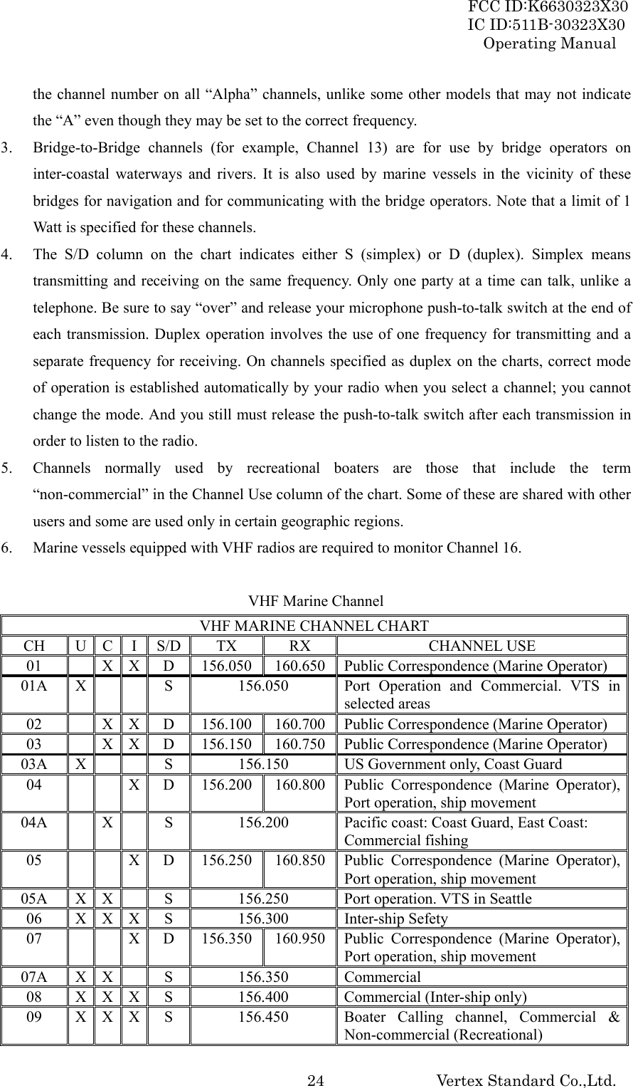
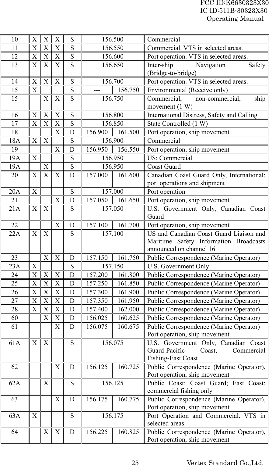
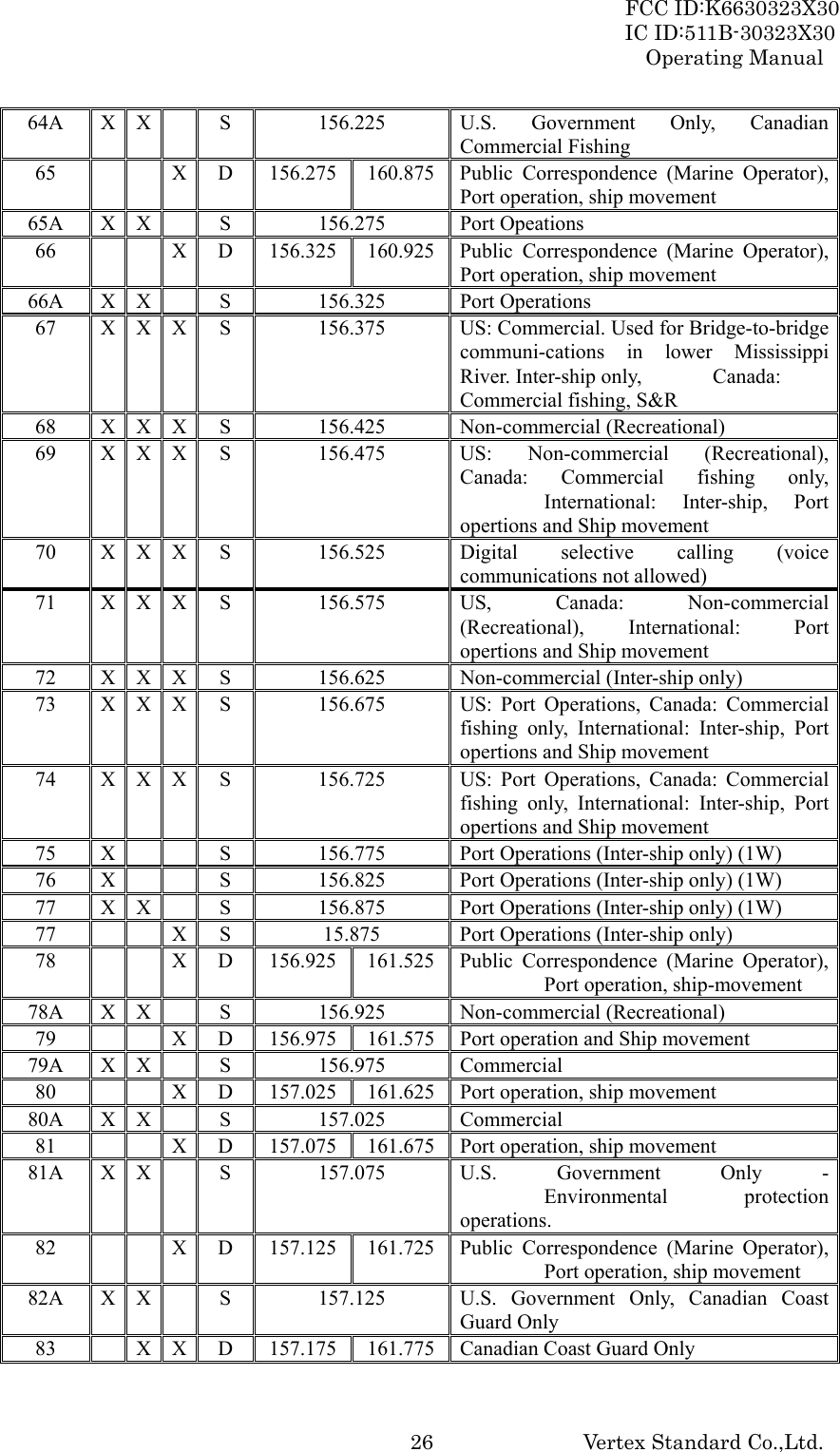
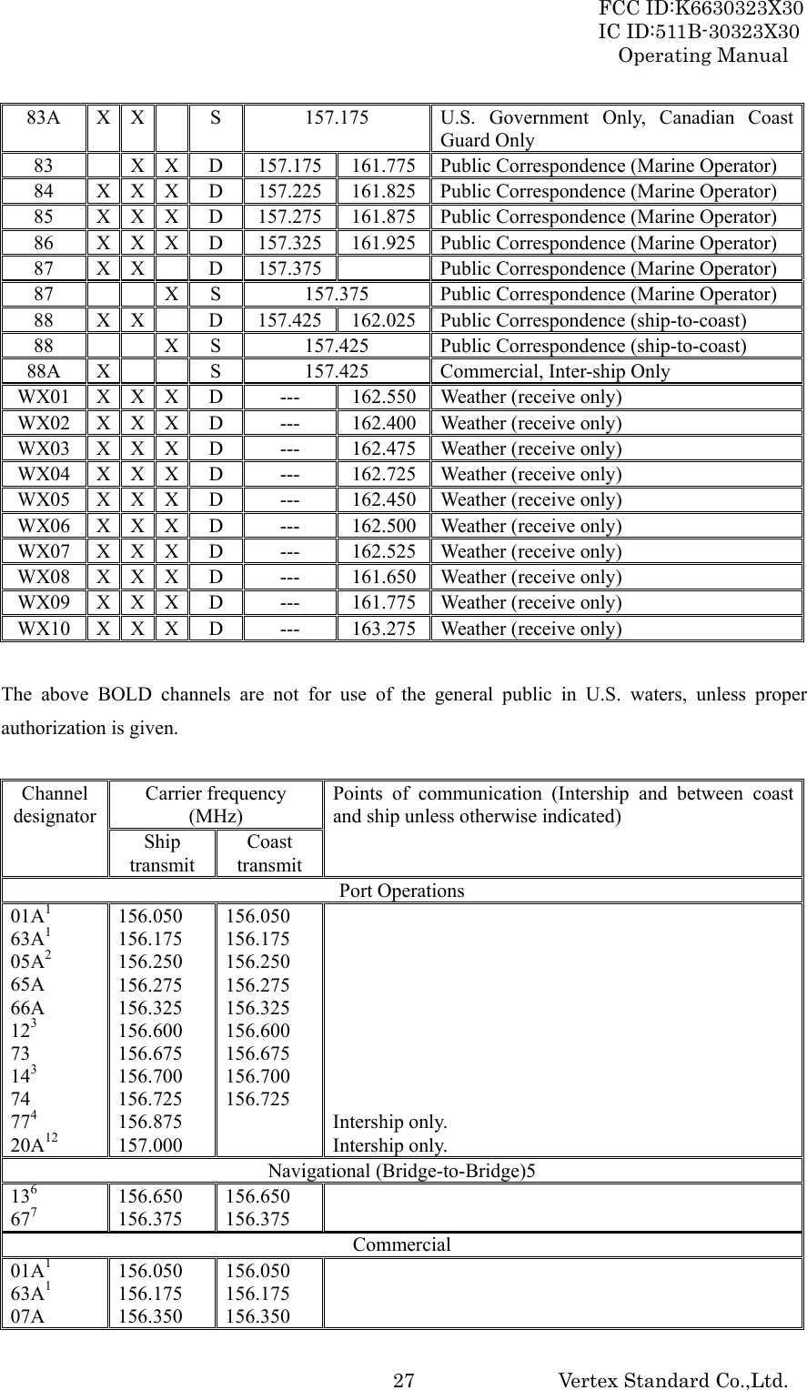
![FCC ID:K6630323X30 IC ID:511B-30323X30 Operating Manual Vertex Standard Co.,Ltd. 126.4 TRANSMISSION 1. Perform steps 1 through 7 of the “6.3 RECEPTION” discussion above. 2. Before transmitting, monitor the channel and make sure it is clear. THIS IS AN FCC REQUIREMENT! 3. For communications over short distances, press the [H/L] key until “L” is displayed on the LCD. This indicates Low power (approximately 1 watt). Note: Transmitting on 1 watt prolongs battery life. Low power (1 watt) should be selected whenever possible. 4. If using Low power is not effective, select Medium power (2.5 watts: “M” icon appears), High power (5 watts: “H” icon appears), or Normal power (6 watts: No icon) by pressing the [H/L] key. 5. When receiving a signal, wait until the incoming signal stops before transmitting. The transceiver cannot transmit and receive simultaneously. 6. Press the PTT (Push-To-Talk) switch to transmit. During transmission, the “TX” indicator will appear on the display and the TX/BUSY indicator will grow red. 7. Speak slowly and clearly into the microphone. Hold the microphone about 1 inch (2.5 cm) away from your mouth. 8. When the transmission is finished, release the PTT switch. 6.4.1 TRANSMIT TIME - OUT TIMER (TOT) While the PTT switch is held down, transmission time is limited to 5 minutes. This prevents prolonged (unintentional) transmissions. About 10 seconds before automatic transmitter shutdown, a warning beep sounds from the speaker. The transceiver automatically switches to the receiving mode, even if the PTT switch is held down. Before transmitting again, the PTT switch must first be released, and then pressed again. This Time-Out-Timer (TOT) prevents a continuous transmission that would result from an accidentally stuck PTT switch. 6.5 USA, CANADIAN, AND INTERNATIONAL CHANNELS 1. To change from US to Canadian or International Marine Channels, hold down the [16/9] key and press the [WX] key. The band will change from USA, to International, and to Canadian with each press. 2. “USA” appears on the LCD for the USA band, “CAN” appears for the Canadian band, and “INTL” appears for the International band. 3. Refer to the marine channel charts in section 16 “VHF MARINE CHANNEL ASSIGNMENTS” for allocated channels.](https://usermanual.wiki/Yaesu-Musen/30323X30/User-Guide-897628-Page-12.png)
![FCC ID:K6630323X30 IC ID:511B-30323X30 Operating Manual Vertex Standard Co.,Ltd. 136.6 SIMPLEX/DUPLEX CHANNEL USE Refer to the VHF MARINE CHANNEL CHART (page ??) for instructions on use of simplex and duplex channels. NOTE All channels are factory-programmed in accordance with FCC (USA), Industry Canada and International regulations. The mode of operation cannot be altered from simplex to duplex or vice-versa. Simplex (ship to ship) or duplex (marine operator) mode is automatically activated, depending on the channel and whether the USA, International or Canadian operating band is selected. 6.7 NOAA WEATHER CHANNELS 1. To receive a NOAA weather broadcast, press the [WX] key. The transceiver changes to the weather channel mode. This mode consists of a special preset memory bank containing the NOAA weather channels. 2. The transceiver will be set to the last used NOAA weather channel. Press the [T] or [S] key to change to other weather channels. 3. To exit from the weather channel mode, press the [WX] key. The transceiver will revert to the channel you were using prior to switching to the weather channel mode. 6.7.1 NOAA WEATHER ALERT In the event of extreme weather disturbances such as storms and hurricanes, NOAA (National Oceanic and Atmospheric Administration) sends a “weather alert” consisting of a 1050 Hz tone, followed by weather reports on the weather channels. The transceiver is capable of receiving this alert if the following is performed: 1. Program your area’s weather channels into the transceiver’s scan memory. Follow the same procedure as for regular channels. 2. Press the [SCAN(DW)] key to start the scan. 3. The memorized weather channels are scanned along with the regular memorized channels. Scanning will not stop on the (continuous) weather broadcast channels unless the weather alert tone is received. 4. When an alert is received on a weather channel, scanning stops and the transceiver emits a beeping tone that will stay on for 5 minutes. 5. Press the [WX] key to listen to the Weather Alert. 6.7.2 NOAA WEATHER ALERT TESTING In the event of a major storm or other appreciable weather condition requiring vessels at sea (or other bodies of water) to be notified, the NOAA (National Oceanographic and Atmospheric Administration) broadcasts a 1050 Hz tone that some VHF radios, including your HX750S, can](https://usermanual.wiki/Yaesu-Musen/30323X30/User-Guide-897628-Page-13.png)
![FCC ID:K6630323X30 IC ID:511B-30323X30 Operating Manual Vertex Standard Co.,Ltd. 14detect for “Weather Alarm” purposes (refer to section 6.7.1 “NOAA WEATHER ALERT” for a discussion of how to use this feature). The 1050 Hz tone, when detected, will produce a loud beep in the speaker of the HX750S, to signal that a Weather Alert Broadcast is being received. In order to test this system, NOAA broadcasts the 1050 Hz tone every Wednesday sometime between 11 AM and 1 PM local time. You may use this opportunity to test your HX750S periodically to confirm that the Weather Alert feature is working, or for training crew members on how to configure the HX750S to receive the NOAA Weather Alerts. 6.8 PRESET CHANNELS (0 ~ 9): INSTANT ACCESS Ten user assigned channels can be programmed for instant access. Pressing the [PRESET] key activates the user assigned channel bank. If the [PRESET] key is pressed and no channels have been assigned, an alert beep will be emitted twice from the speaker. Programming 1. Hold down the [PRESET] key, and press the [T] or [S] key (repeatedly, if necessary) until the desired channel number is displayed. 2. With the desired channel number displayed, release the [PRESET] key. The Preset Channel number “0” will appear at the right of the channel number on the display. 3. Repeat steps 1 and 2 to program the desired channels into Preset Channels “1” ~ “9.” 4. To delete a Preset Channel, hold down the [PRESET] key and press the [T] or [S] key until the Preset Channel number to be deleted is displayed, then release the [PRESET] key. Operation Pressing the [PRESET] key will toggle between Preset Channels “0” through “9” and the last selected “regular” channel. 6.9 MEMOY SCAN The HX750S can be programmed to scan channels from a minimum of 2 channels up to all channels in the marine band. If an incoming signal is detected on one of the channels during scan, the radio will pause on that channel, allowing you to listen to the incoming transmission. 1. Select the desired channel to be included in the scan memory using the [T] or [S] key. 2. Press the [MEM] key to store the channel into the transceiver’s scan memory. “MEM” will be displayed on the LCD. 3. Repeat steps 1 and 2 for all the channels to be scanned. 4. To delete a channel from the transceiver’s scan memory, select the memorized channel, then press the [MEM] key until “MEM” is removed from the display.](https://usermanual.wiki/Yaesu-Musen/30323X30/User-Guide-897628-Page-14.png)
![FCC ID:K6630323X30 IC ID:511B-30323X30 Operating Manual Vertex Standard Co.,Ltd. 155. All channels programmed remain in the transceiver’s scan memory even if the power is turned off. See section 11 “RESETTING THE TRANSCEIVER’S MICROPROCESSOR” for clear all channels from the transceivers scan memory. 6. Adjust the SQL level until background noise is eliminated by pressing the [SQL] key followed by the [T] / [S] key. 7. To start scanning, press the [SCAN(DW)] key. The scan proceeds from the lowest to the highest programmed channel and stops scanning when a transmission is received. Scanning will resume when the incoming signal disappears at the end of the transmission. A blinking “SCN” icon will appears at the left bottom of the display during scanning. 8. To stop the scan, press the [SCAN(DW)] key. 6.10 PRIORITY SCAN The Priority Scanning feature allows the radio to Memory Scan while also keeping watch on a particularly important “Priority Channel”. The following channels can be set as the Priority Channel: 16, 09, and Preset Channels described previously. 1. To set the priority channel, hold down the [16/9] key and press the [MEM] key. The channel will change from “16” to “09” to Preset Channels “0” through “9” with each press of the [MEM] key. When the [16/9] key is released the displayed channel will be set as the Priority Channel (the “P” icon will appear at the left side of the channel number). 2. For Priority Scanning, press the [SCAN(DW)] key to activates the Memory Scanning, then hold down the [SCAN(DW)] key while activating the Memory Scan. Scanning will proceed between the memorized channels and the Priority Channel. The Priority Channel will be scanned after each programmed channel. 3. As an example of priority scanning, let us say that marine channels “06”, “07”, and “08” are memorized in the transceiver’s scan memory. Priority scanning will proceed in the following sequence: [CH06] Æ [Priority Channel] Æ [CH07] Æ [Priority Channel] Æ [CH08] Æ [Priority Channel] Æ [CH06] Æ [Priority Channel] ………… 4. Even when the transceiver stops and listens to the signal of a programmed channel, the transceiver will shift to a “dual watch” mode between this channel and the priority channel. Therefore, your priority watching of the designated channel is not compromised when the scanner has paused on an active channel. 5. Hold down the [SCAN(DW)] key to change the Priority Scan to Memory Scan, and then press the [SCAN(DW)] key to stop the scan and return to normal operation. 6.11 DUAL WATCH](https://usermanual.wiki/Yaesu-Musen/30323X30/User-Guide-897628-Page-15.png)
![FCC ID:K6630323X30 IC ID:511B-30323X30 Operating Manual Vertex Standard Co.,Ltd. 16The Dual Watch feature allows the radio watch the particularly important “Priority Channel” (determined section “6.10 PRIORITY SCAN”) while receiving the current channel. 1. Select the desired channel using the [T] or [S] key. 2. Hold down the [SCAN(DW)] key for two seconds, then release the key to activate the Dual Watch feature. A small blinking “DW” icon will appear on the center bottom of the display when the Dual Watch feature is activated. 3. When a transmission is received on the “Priority Channel”, the radio receives the “Priority Channel” until the incoming signal disappears. 4. The Dual Watch feature will resume when the incoming signal disappears at the end of the transmission. 5. Press the [SCAN(DW)] key to stop the Dual Watch feature and return to normal operation. 6.12 TRIPLE WATCH The Triple Watch feature is similarly the Dual Watch feature. The Triple Watch feature watches the channel “16” and “09” while receiving the current channel. Setting Up Triple Watch feature 1. Turn the transceiver off. 2. Hold down the [SQL] key, and then turn on the transceiver while still holding down the [SQL] key. 3. The “SEt” will appear on the display, indicating that the Menu (“Set”) Mode has been activated. 4. Press the [SQL] key to select the Menu item “09 dt”. 5. Press the [T] or [S] key to select “t-”, indicating that the Triple Watch feature is selected. 6. Press the [SQL] key to save the new setting, then press the PTT key to exit to normal operation. Operation 1. Select the desired channel using the [T] or [S] key. 2. Hold down the [SCAN(DW)] key for two seconds, then release the [SCAN(DW)] key to activate the Triple Watch feature. The radio watches the channel “16” and “09” while receiving the current channel. A small blinking “DW” icon will appear on the center bottom of the display when the Triple Watch feature is activated. • When a transmission is received on the channel “16”, the radio receives the channel “16” until the incoming signal disappears. • When a transmission is received on the channel “09”, the radio watches the channel “16” while receiving the channel “09”. 3. The Triple Watch feature will resume when the incoming signal disappears at the end of the](https://usermanual.wiki/Yaesu-Musen/30323X30/User-Guide-897628-Page-16.png)
![FCC ID:K6630323X30 IC ID:511B-30323X30 Operating Manual Vertex Standard Co.,Ltd. 17transmission. 4. Press the [SCAN(DW)] key to stop the Triple Watch feature and return to normal operation. To return to the Dual Watch operation, repeat the “Setting Up Triple Watch feature”, selecting “d-” in step 5. 6.13 EMERGENCY (CHANNEL 16 USE) Channel 16 is known as the Hail and Distress Channel. An emergency may be defined as a threat to life or property. In such instances, be sure the transceiver is on and set to CHANNEL 16. Then use the following procedure: 1. Press the microphone push-to-talk switch and say “Mayday, Mayday, Mayday. This is _____, _____, _____” (your vessel’s name). 2. Then repeat once: “Mayday, _____” (your vessel’s name). 3. Now report your position in latitude/longitude, or by giving a true or magnetic bearing (state which) to a well-known landmark such as a navigation aid or geographic feature such as an island or harbor entry. 4. Explain the nature of your distress (sinking, collision, aground, fire, heart attack, life-threatening injury, etc.). 5. State the kind of assistance your desire (pumps, medical aid, etc.). 6. Report the number of persons aboard and condition of any injured. 7. Estimate the present seaworthiness and condition of your vessel. 8. Give your vessel’s description: length, design (power or sail), color and other distinguishing marks. The total transmission should not exceed 1 minute. 9. End the message by saying “OVER” Release the microphone button and listen. 10. If there is no answer, repeat the above procedure. If there is still no response, try another channel. 6.14 CALLING ANOTHER VESSEL (CHANNEL 16 OR 9) Channel 16 may be used for initial contact (hailing) with another vessel. However, its most important use is for emergency messages. This channel must be monitored at all times except when actually using another channel. It is monitored by the U.S. and Canadian Coast Guards and by other vessels. Use of channel 16 for hailing must be limited to initial contact only. Calling should not exceed 30 seconds, but may be repeated 3 times at 2-minute intervals. In areas of heavy radio traffic, congestion on channel 16 resulting from its use as a hailing channel can be reduced significantly in U.S. waters by using Channel 9 as the initial contact (hailing) channel for non-emergency communications. Here, also, calling time should not exceed 30 seconds but may be repeated 3 times at 2-minute intervals.](https://usermanual.wiki/Yaesu-Musen/30323X30/User-Guide-897628-Page-17.png)
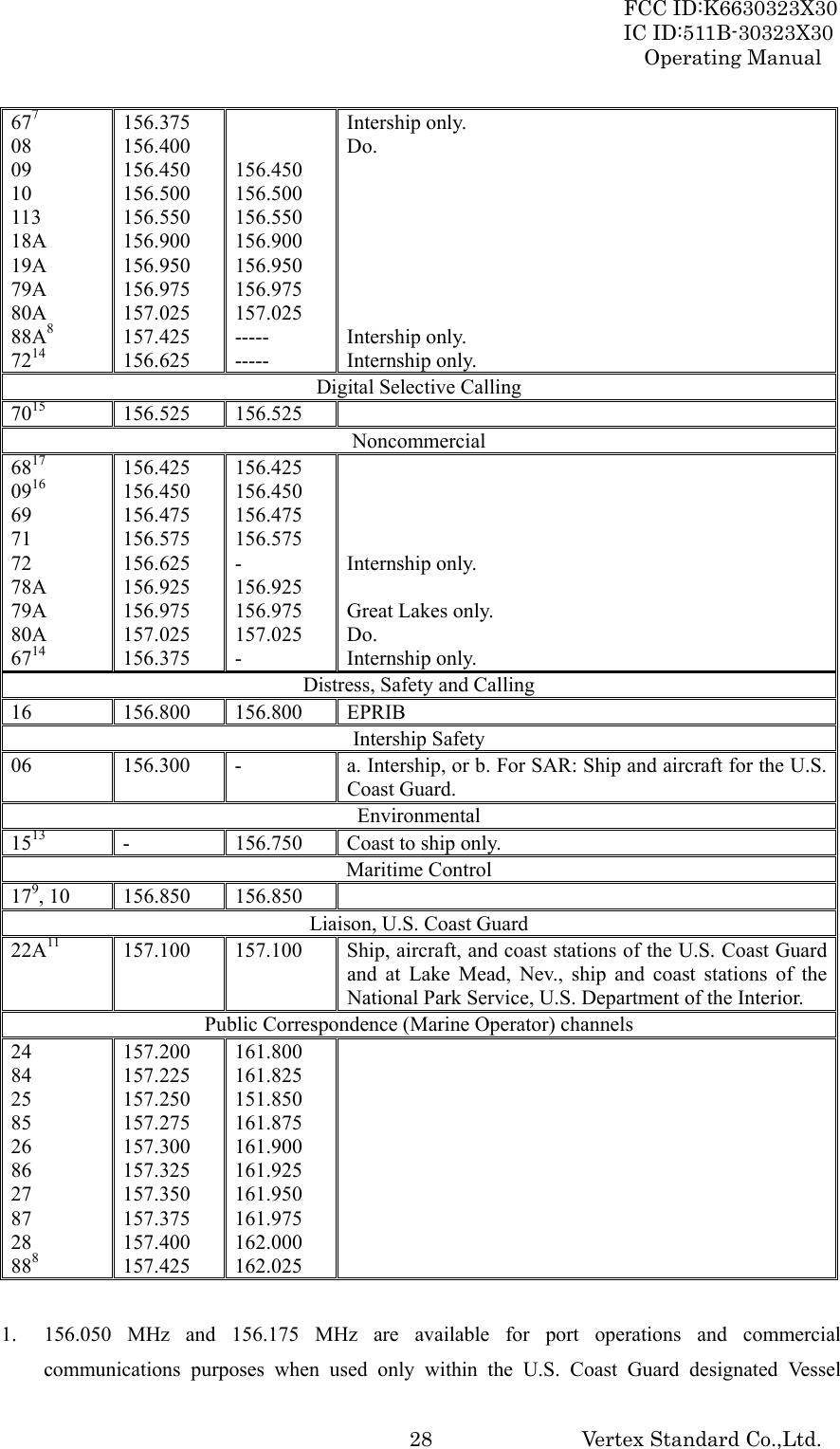
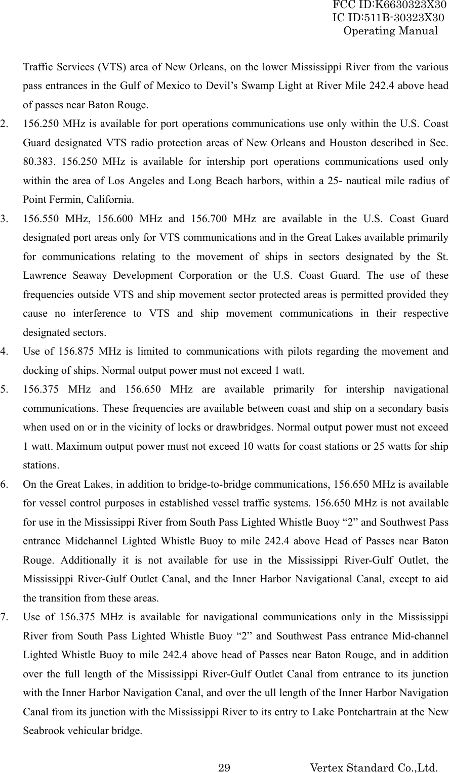
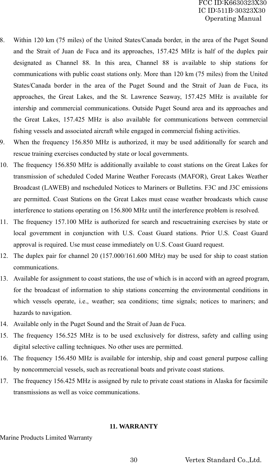
![FCC ID:K6630323X30 IC ID:511B-30323X30 Operating Manual Vertex Standard Co.,Ltd. 18Prior to making contact with another vessel, refer to the channel charts in this manual, and select an appropriate channel for communications after initial contact. For example, Channels 68 and 69 of the U.S. VHF Charts are some of the channels available to non-commercial (recreational) boaters. Monitor your desired channel in advance to make sure you will not be interrupting other traffic, and then go back to either channel 16 or 9 for your initial contact. When the hailing channel (16 or 9) is clear, state the name of the other vessel you wish to call and then “this is” followed by the name of your vessel and your Station License (Call Sign). When the other vessel returns your call, immediately request another channel by saying “go to”, the number of the other channel, and “over.” Then switch to the new channel. When the new channel is not busy, call the other vessel. After a transmission, say “over”, and release the microphone’s push-to-talk (PTT) switch. When all communication with the other vessel is completed, end the last transmission by stating your Call Sign and the word “out”. Note that it is not necessary to state your Call Sign with each transmission, only at the beginning and end of the contact. Remember to return to Channel 16 when not using another channel. Some radios automatically monitor Channel 16 even when set to other channels or when scanning. 6.15 OPERATING ON CHANNELS 13 AND 67 Channel 13 is used at docks and bridges and by vessels maneuvering in port. Messages on this channel must concern navigation only, such as meeting and passing in restricted waters. Channel 67 is used for navigational traffic between vessels. By regulation, power is normally limited to 1 Watt on these channels. Your radio is programmed to automatically reduce power to this limit on these channels. However, in certain situations it may be necessary to temporarily use a higher power. See page ?? ([H/L] key) for means to temporarily override the low-power limit on these two channels. 6.15 OPERATING ON CHANNEL 13 Channel 13 is used at docks, bridges and for maneuvering in port. Messages on this channel must concern navigation only, such as meeting and passing in restricted waters. In emergencies and when approaching blind river bends, High power is allowed. Pressing the [H/L(KEY)] key will change the power output from Low Power (1 Watt) to Medium (2.5 Watts), High (5 Watts), or Normal (6 Watts) power will be selected. When you select to this channel again, the transceiver will revert to Low power. 6.16 OPERATING ON CHANNEL 67 When channel 67 is used for navigational bridge-to-bridge traffic between ships, Normal, High or](https://usermanual.wiki/Yaesu-Musen/30323X30/User-Guide-897628-Page-18.png)
![FCC ID:K6630323X30 IC ID:511B-30323X30 Operating Manual Vertex Standard Co.,Ltd. 19Medium power may be used temporarily (in the USA band) by pressing the [H/L(KEY)] key. When you select to this channel again, the transceiver will revert to low power. 6.17 ENABLING S.O.S STROBE OPERATION The S.O.S. STROBE feature utilizes the high-intensity strobe LED on the front of the HX750S as a visual distress beacon. When enabled, the LED blinks the internationally-recognized Morse Code “S.O.S.” message (...---...) at a rate of 5 words per minute. This can be very useful in summoning help from rescuers who may not be able to communicate with you via radio. 1. Hold down the [MEM] key while turning the radio on to activate the emergency S.O.S. Strobe. Once the radio comes on, the BUSY/TX LED will flash the Morse Code S.O.S. message repeatedly. 2. The S.O.S. strobe function is interrupted when a signal is received or if the squelch control is turned so audio is heard from the speaker and during transmission. 3. To disable the S.O.S. strobe function, turn the radio off and back on again. 7. MENU (“SET”) MODE The HX750S’s Menu Mode allows a number of the HX750S operating parameters to be custom-configured for your operating requirements. The Menu Mode is easy to activate and set, using the following procedure: 1. Turn the transceiver off. 2. Hold down the [SQL] key, and then turn on the transceiver while still holding down the [SQL] key. 3. The “SEt” will appear on the display, indicating that the Menu (“Set”) Mode has been activated. 4. Press the [SQL] key to select the Menu item to be adjusted. 5. Press the [T] or [S] key to enable adjustment of the selected Menu item. The menu item will blink 6. Press the [SQL] key to select the status or value of the Menu item. 7. After completing your adjustment, press the PTT key to save the new setting and exit to normal operation. 01 bEP (BEEP) Function: Enable/Disable the Keypad beeper. Available Values: on / oFF Default: on](https://usermanual.wiki/Yaesu-Musen/30323X30/User-Guide-897628-Page-19.png)
![FCC ID:K6630323X30 IC ID:511B-30323X30 Operating Manual Vertex Standard Co.,Ltd. 22 13 ALt (WX ALERT) Function: Enable/Disable the Weather Alert feature. Available Values: on / SCn / on SC / oFF Default: oFF 8. MAINTENANCE 8.1 GENERAL The inherent quality of the solid-state components in STANDARD HORIZON radios will provide many years of continuous use. Take the following precautions to prevent damage to the radio. To prevent corrosion of electrical contacts and keep the water resistance, keep the microphone connected or the jack covered at all times. Never key the transmitter unless an antenna or suitable dummy load is connected to the antenna receptacle. Ensure that the input voltage does not exceed the value specified in your Owner’s Manual. Use only STANDARD HORIZON-approved accessories and replacement parts. 8.2 REPLACEMENT PARTS Occasionally an owner needs a replacement parts. These can be ordered from our Parts Department by writing or calling: Marine Division of Vertex Standard US Headquarters 10900 Walker Street, Cypress, CA 90630, U.S.A. Telephone (714) 827-7600 Commonly requested parts, and their part numbers are listed below. • CD-39 Charger Cradle: xxxxxxxxx • MIC/SP Cover: xxxxxxxxx 8.3 TROUBLESHOOTING CHART SYMPTOM PROBABLE CAUSE REMEDY The [SCAN(DW)] key does not start the scan. No channels memorized. Use the [MEM] key to enter desired channels into the transceiver’s memory.](https://usermanual.wiki/Yaesu-Musen/30323X30/User-Guide-897628-Page-22.png)
![FCC ID:K6630323X30 IC ID:511B-30323X30 Operating Manual Vertex Standard Co.,Ltd. 23Squelch is not adjusted. Adjust the squelch to the point where noise just disappears. Further adjustment of the squelch control may eliminate incoming signals. The USA/INTL/CAN modes do not function. Proper operation not followed. Hold down the [16/9] key and press the [WX] key. Cannot change any function. Key Lock is on. Turn Key Lock off. Refer to section 5, 5 LAMP key. Key Lock does not function. Proper operation not followed. Hold down the LAMP key for 1 second. Indicator does not light when charging a battery. Defective battery FNB-V99LI. Contact your Standard Horizon dealer. 9. INSTALLATIONS OF OPTION 9.1 FBA-38 BATTERY CASE FBA-38 is a battery case that holds five LR03 alkaline batteries and is used with the HX750S transceiver. 1. Slide the five LR03 alkaline batteries into the FBA-38 with the Negative (–) side of the batteries touching the spring connections inside the FBA-38. 2. Insert the FBA-38 into the battery nest on the bottom of the transceiver, and then turn the Battery Pack Lock to the “LOCK” position by a coin. 10. VHF MARINE CHANNEL ASSIGNMENTS Tables on the following pages list the VHF Marine Channel assignments for U.S.A. and International use. Below are listed some data about the charts. 1. VTS. Where indicated, these channels are part of the U.S. Coast Guard’s Vessel Traffic System. 2. Alpha channel numbers, that is, channel numbers followed by the letter A (such as Channel 07A) are simplex channels on the U.S.A. or Canadian channel assignments whose counterparts in the International assignments are duplex channels. International channels do not use “alpha” numbers. If you call the Coast Guard on Channel 16, they will sometimes ask you to “go to channel 22 Alpha.” This is a channel assigned to U.S.A, and Canadian Coast Guards for handling distress and other calls. If your radio is set for International operation you will go to Channel 22 instead of 22A, and will not be able to communicate with the Coast Guard. To use Channel 22A, your radio must be set for USA or Canada operation, using the USA/CAN/INTL channel selection procedure described on page ?? of this manual. Channel 22 (without an “A” is an International duplex channel for port operations. The HX750S displays an “A” adjacent to](https://usermanual.wiki/Yaesu-Musen/30323X30/User-Guide-897628-Page-23.png)