Yaesu Musen 30493X20 Handheld Marine Transceiver with WX User Manual
Yaesu Musen Co., Ltd. Handheld Marine Transceiver with WX
UserManual.wiki
>
Yaesu Musen
>
30493X20 User Manual
User Manual
Navigation menu
Upload a User Manual
Namespaces
Wiki Guide
HTML
PDF
Info
Views
User Manual
Discussion / Help
Navigation
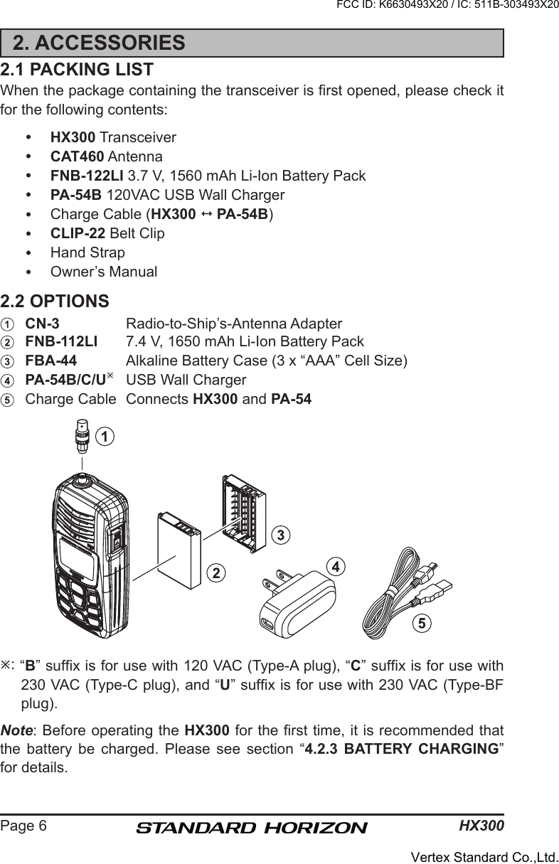
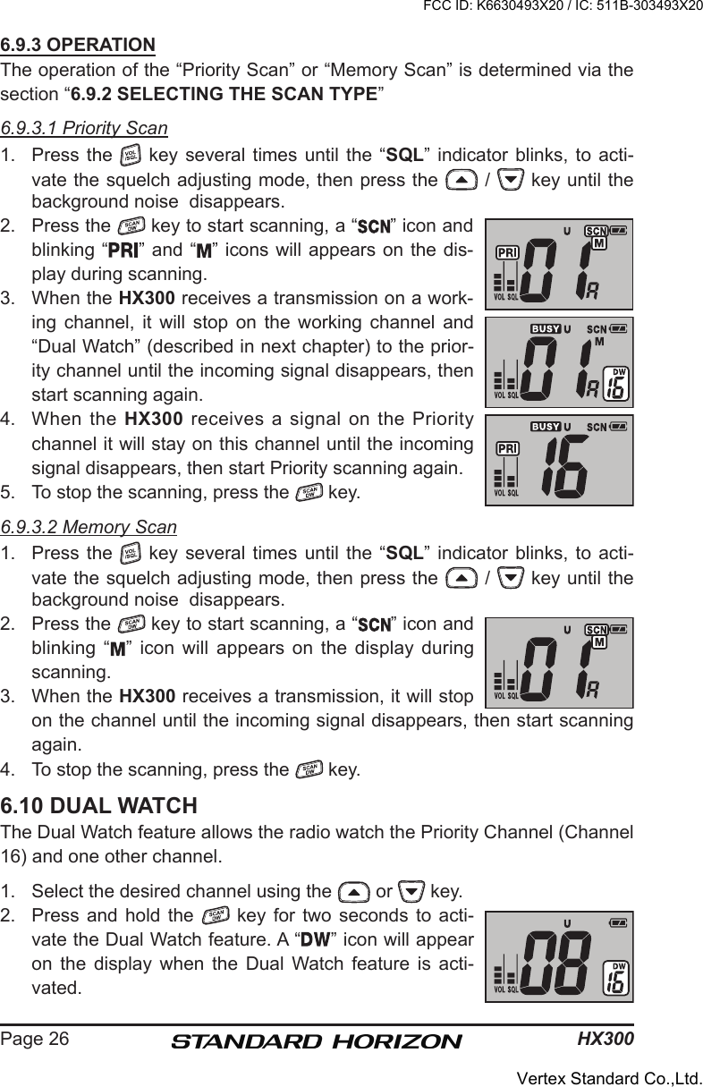
![Page 41HX30011. SPECIFICATIONSPerformance specications are nominal, unless otherwise indicated, and are subject to change without notice.11.1 GENERALFrequency Ranges: TX: 156.025 MHz - 157.425 MHz RX: 156.050 MHz - 163.275 MHzFrequency Stability: ±5 ppm (–4 °F to +140 °F [–20 °C to +60 °C])Emission Type: 16K0G3EAntenna Impedance: 50 Current Consumption: 330 mA (Receive, Typical at AF MAX.) 20 mA (Standby) 2.3 A (TX at 5 W)Battery Life: 10 hours (Approx.) (5/5/9 duty cycle)Operating Temperature: –4 °F to +140 °F (–20 °C to +60 °C)Case Size (W x H x D): 2.32” x 5.04” x 1.30” (59 x 128 x 33 mm) (w/o knob & antenna)Weight (Approx.): 8.4 oz (240 g) (w/o FNB-122LI, Belt Clip, & Antenna)11.2 TRANSMITTERRF Power Output: 5 W / 1 W (@3.7 V )Maximum Deviation: ±5 kHzSpurious Emission: –75 dBc typical11.3 RECEIVERCircuit Type: Double-Conversion SuperheterodyneSensitivity: 0.25 µV for 12 dB SINADAdjacent Channel Selectivity: 70 dB typicalIntermodulation: 68 dB typicalHum & Noise Ratio: 40 dB typicalAF Output (Internal SP): 600 mW @8 for 10 % THD (@3.7 V)Measured in accordance with TIA/EIA-603.FCC ID: K6630493X20 / IC: 511B-303493X20Vertex Standard Co.,Ltd.](https://usermanual.wiki/Yaesu-Musen/30493X20/User-Guide-1638378-Page-41.png)