Yaesu Musen 30553X20 HANDHELD MARINE TRANSCEIVER User Manual Operating Manual
Yaesu Musen Co., Ltd. HANDHELD MARINE TRANSCEIVER Operating Manual
UserManual.wiki
>
Yaesu Musen
>
30553X20 User Manual
Corrected User Manual
Navigation menu
Upload a User Manual
Namespaces
Wiki Guide
HTML
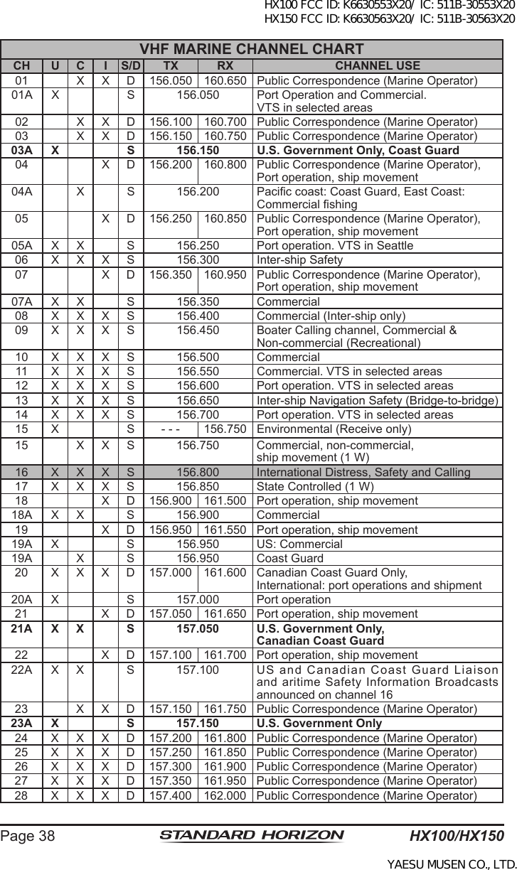
PDF
Info
Views
User Manual
Discussion / Help
Navigation
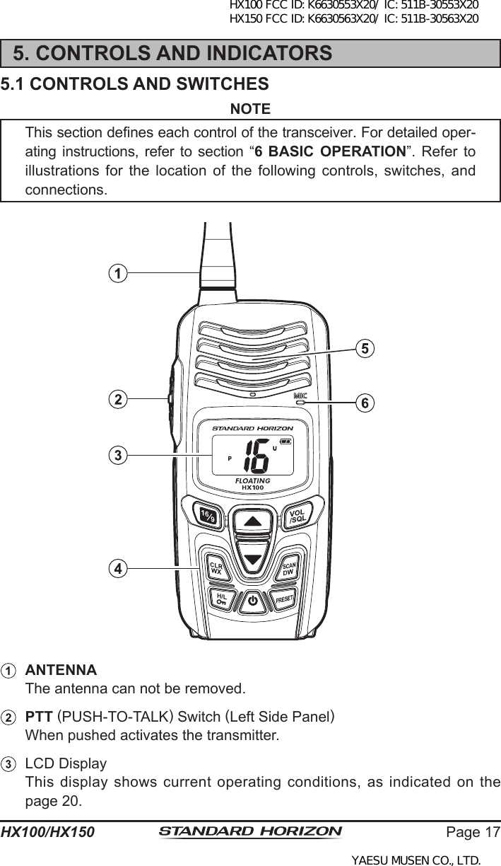
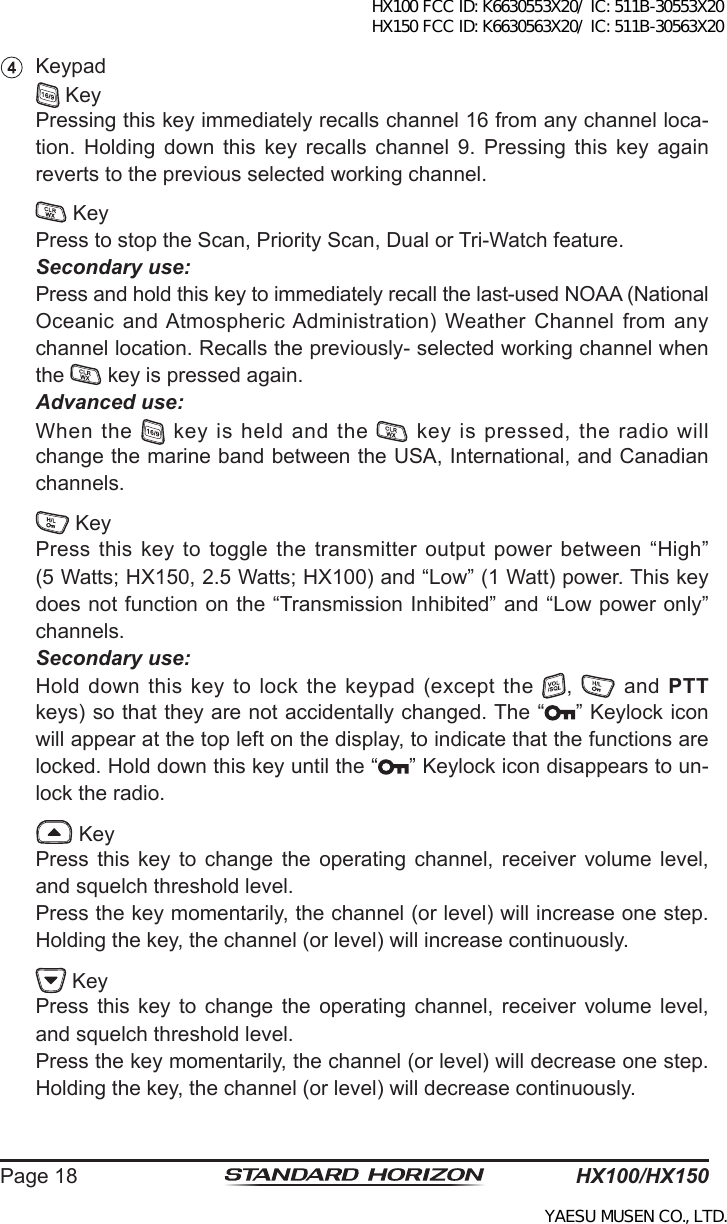
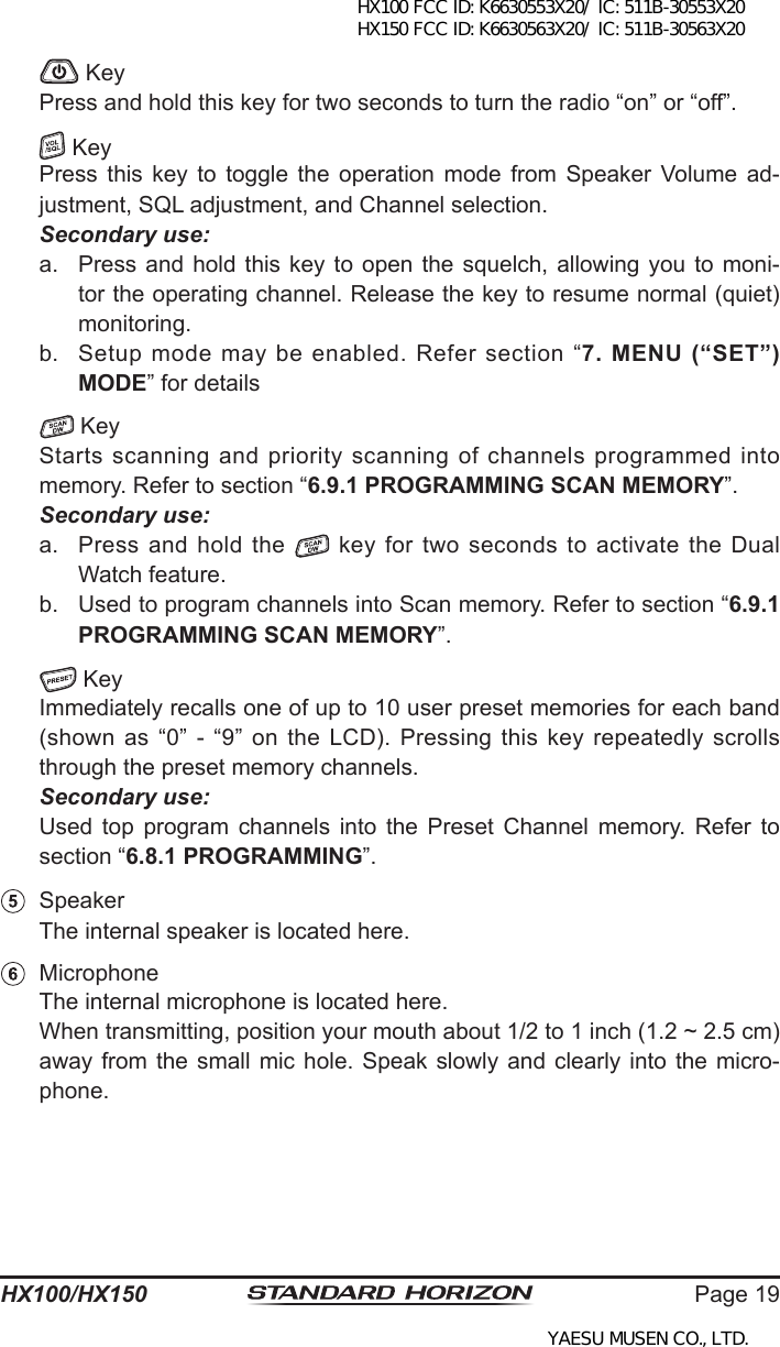
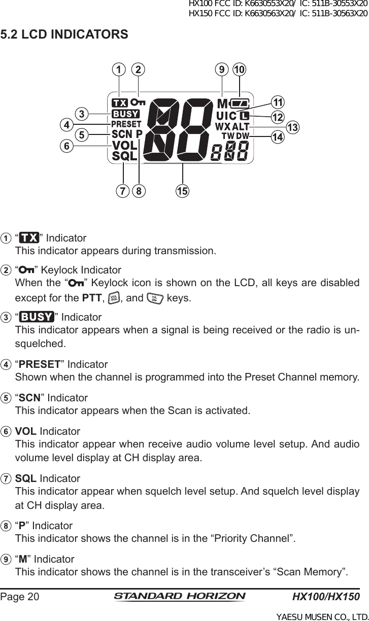
![HX100/HX150Page 4411. SPECIFICATIONSPerformance specications are nominal, unless otherwise indicated, and are subject to change without notice.11.1 GENERALFrequency Ranges: TX: 156.025 MHz - 157.425 MHz RX: 156.050 MHz - 163.275 MHzChannel Spacing: 25 kHzFrequency Stability: ±5 ppm (–4 °F to +140 °F [–20 °C to +60 °C])Emission Type: 16K0G3EAntenna Impedance: 50 Operating Voltage: HX100: 4.8 V DC, Negative Ground HX150: 7.4 V DC, Negative GroundCurrent Consumption: HX100: 250 mA (Receive, Typical at AF MAX.) HX150: 300 mA (Receive, Typical at AF MAX.) 15 mA (Standby) HX100: 1.1 A / 0.8 A (TX: 2.5 W / 1 W) HX150: 1.4 A / 0.7 A (TX: 5 W / 1 W)Battery Life (Approx.): HX100: 7 hours (5/5/90 duty cycle) HX150: 8 hours (5/5/90 duty cycle)Operating Temperature: –4 °F to +140 °F (–20 °C to +60 °C)Case Size (W x H x D): 2.4” x 5.3” x 1.5” (62 x 135 x 38.5 mm)(w/o knob & antenna)Weight (Approx.): HX100: 8.6 oz (245 g)(with FNB-125, Belt Clip) HX150: 8.3 oz (235 g)(with FNB-124LI, Belt Clip)11.2 TRANSMITTERRF Power Output: HX100: 2.5 W / 1 W (@4.8 V ) HX150: 5 W / 1 W (@7.4 V )Modulation Type: Variable ReactanceMaximum Deviation: ±5 kHzSpurious Emission: –65 dBc typicalMicrophone Impedance: 2 kHX100 FCC ID: K6630553X20/ IC: 511B-30553X20 HX150 FCC ID: K6630563X20/ IC: 511B-30563X20YAESU MUSEN CO., LTD.](https://usermanual.wiki/Yaesu-Musen/30553X20/User-Guide-1764913-Page-44.png)