Yaesu Musen 30613X30 HANDHELD MARINE TRANSCEIVER User Manual Operating
Yaesu Musen Co., Ltd. HANDHELD MARINE TRANSCEIVER Operating
UserManual.wiki
>
Yaesu Musen
>
30613X30 User Manual
Operating User Manual
Navigation menu
Upload a User Manual
Namespaces
Wiki Guide
HTML
PDF
Info
Views
User Manual
Discussion / Help
Navigation
![Page 1HX2101. GENERAL INFORMATION1.1 INTRODUCTIONCongratulations on your purchase of the HX210! Whether this is your first portable marine VHF transceiver, or if you have other STANDARD HORIZON equipment, the STANDARD HORIZON organization is commit-ted to ensuring your enjoyment of this high performance transceiver, which should provide you with many years of satisfying communications even in the harshest of environments. STANDARD HORIZON technical support personnel stands behind every product sold, and we invite you to contact us should you require technical advice or assistance by calling (800)767-2450 Monday through Friday 8AM to 5PM Pacic time.The HX210 is a Submersible Floating 6-Watt portable two way marine trans-ceiver. The transceiver has all allocated USA, International, or Canadian channels. It has emergency channel 16 which can be immediately selected from any channel by pressing the [16/S] key.The HX210 includes the following features: Memory Scanning, Priority Scanning, Dual and Triple watch, NOAA Weather Alert, easy-to-read large LCD display, Battery Life displayed on LCD, and a transmit Time-Out Timer (TOT).The HX210 transmitter provides a full 6 Watt of transmit power and also is selectable to 1 Watt to assist the user in ensuring maximum battery life.We appreciate your purchase of the HX210, and encourage you to read this manual thoroughly, so as to learn and fully understand the capabilities of the HX210.FCC ID: K6630613X30 IC: 511B-30613X30](https://usermanual.wiki/Yaesu-Musen/30613X30/User-Guide-3494641-Page-3.png)
![Page 13HX2106. BASIC OPERATION6.1 PROHIBITED COMMUNICATIONSThe FCC prohibits the following communications: False distress or emergency messages: Messages to “any boat” except in emergencies and radio tests; Messages to or from a vessel on land; Transmission while on land; Obscene, indecent, or profane language (potential ne of $10,000).6.2 INITIAL SETUP1. Install the antenna onto the transceiver; hold the bottom end of the an-tenna, then screw it onto the mating connector on the transceiver until it is snug. Do not over-tighten.6.3 RECEPTION1. Press and hold the POWER key for two seconds to turn the radio “on”.2. Press and hold the [SQL] switch until the “ ” indicator will appear on the display. This state is known as “squelch off”.3. Press the VOL−/VOL+ key until noise or audio from the speaker is at a comfortable level.4. Press the [SQL] switch to resume normal (quiet) monitoring.5. Press the [p] or [q] key to select the desired channel. Refer to the chan-nel chart on page 27 for available channels.6. When a signal is received, adjust the volume to the desired listening level. The “ ” indicator on the LCD is displayed indicating that the channel is being used or the radio is not squelched.6.4 TRANSMISSION1. Perform “6.3 RECEPTION” discussion above.2. Before transmitting, monitor the channel and make sure it is clear. THIS IS AN FCC REQUIREMENT!3. Press the PTT (Push-To-Talk) switch to transmit. During transmission, the “ ” indicator will appear on the display.4. Position your mouth about 1/2 to 1 inch (1.2 ~ 2.5 cm) away from the mic hole. Speak slowly and clearly into the microphone.5. When the transmission is nished, release the PTT switch.FCC ID: K6630613X30 IC: 511B-30613X30](https://usermanual.wiki/Yaesu-Musen/30613X30/User-Guide-3494641-Page-15.png)
![HX210Page 146.4.1 TRANSMIT POWERThe TX output power of the HX210 is set to high level (6W) in factory default, and the “HI” indicator is displayed on the top part of the screen.To switch the TX output power:1. Press one of soft keys.2. Press the [◄]/[►] key repeatedly, until the [HI], [MD], or [LO] soft key is displayed at the bottom of the LCD.3. Press the [HI], [MD], or [LO] soft key to switch between HI (6 W), MD (2.5 W), or LO (1 W) output power.6.4.2 TRANSMIT TIME - OUT TIMER (TOT)While the PTT switch is held down, transmission time is limited to 5 minutes. This prevents prolonged (unintentional) transmissions. About 10 seconds before automatic transmitter shutdown, a warning beep will sound from the speaker. The transceiver automatically switches to the receiving mode, even if the PTT switch is held down. Before transmitting again, the PTT switch must rst be released, then wait 10 seconds and then pressed again. This Time-Out-Timer (TOT) prevents a continuous transmission that would result from an accidentally stuck PTT switch.WATER ENABLED LIGHTWhen the HX210 comes in contact with water a white light will blink to assist retrieving it in low light conditions. The light will automatically turn off in about 15 seconds when it is removed from water.6.5 USA, CANADIAN, AND INTERNATIONAL CHANNELSTo change the channel group from USA to International or Canada:1. Press and hold the [MENU/SET] key.2. Press the [▲]/[▼] key to select “CHANNEL SETUP”.3. Press the [SELECT] soft key.4. Press the [▲]/[▼] key to select “CHANNEL GROUP”.5. Press the [SELECT] soft key.6. Press the [▲]/[▼] key to select desired channel group “USA”, “INTER-NATIONAL”, or “CANADA”.7. Press the [ENTER] soft key to store the selected setting.8. Press the [CLR/] key to return to radio operation.FCC ID: K6630613X30 IC: 511B-30613X30](https://usermanual.wiki/Yaesu-Musen/30613X30/User-Guide-3494641-Page-16.png)
![Page 15HX2106.6 KEYPAD LOCKINGIn order to prevent accidental channel change, the HX210’s keypad may be locked.Hold down the [CLR/] key to lock the keypad (except the PTT, VOL+, VOL- and [CLR/ ] keys) so that they are not accidentally changed. Hold down the [CLR/] key to unlock the radio.6.7 NOAA WEATHER CHANNELS1. Press the MENU key to display “MENU”, then press the [WX] soft key. The “WX” indicator appears on the top part of the screen.2. Press the [▲]/[▼] key to select a different NOAA weather channel.3. To exit from the NOAA weather channels, press the [MENU/SET] key to display “MENU”, then press the [CH] soft key. The transceiver returns to the channel it was on prior to a weather channel and the “WX” indicator disappears from the display.6.7.1 NOAA WEATHER ALERTIn the event of extreme weather disturbances, such as storms and hurri-canes, the NOAA (National Oceanic and Atmospheric Administration) sends a weather alert accompanied by a 1050 Hz tone and subsequent weather report on one of the NOAA weather channels.The HX210 can receive weather alerts when monitoring a weather channel and, on the last selected weather channel during scanning modes, while on another working channel or FM Radio mode.When an alert is received on a NOAA weather channel, scanning will stop and the transceiver will emit a loud beep to alert the user of a NOAA broad-cast. Press any key to stop the alert. After stopping the beep sound, the weather alert reception conrmation screen will appear. Press any key to display a conrmation screen. The conrmation screen will ask you whether to move to the weather channel or return in the marine channel. Press [YES] to switch to the weather channel, and press [NO] to return to the marine channel.6.7.2 NOAA WEATHER ALERT TESTINGIn order to test this system, NOAA broadcasts the 1050 Hz tone every Wednesday sometime between 11 AM and 1 PM local time. You may use this opportunity to test your transceiver periodically to confirm that the Weather Alert feature is working, or for training crew members on how to congure the transceiver to receive the NOAA Weather Alerts.FCC ID: K6630613X30 IC: 511B-30613X30](https://usermanual.wiki/Yaesu-Musen/30613X30/User-Guide-3494641-Page-17.png)
![HX210Page 166.8 PRESET CHANNELS: INSTANT ACCESS10 preset channels can be programmed for instant access. Press one of soft key. Press the [◄]/[►] key repeatedly, then press the [PRESET] soft key. Pressing the [PRESET] key activates the user assigned channel bank. If the [PRESET] soft key is pressed and no channels have been assigned, an alert beep will be emitted from the speaker.6.8.1 PROGRAMMING1. Select the desired channel to be assigned into the Preset Channel Bank using the [▲]/[▼] key.2. Press one of soft keys.3. Press the [◄]/[►] key repeatedly, until the [P-SET] soft key is displayed at the bottom of the LCD.4. Press and hold the [P-SET] soft key until the “P-SET” icon and channel number are blinking.5. Press the [ADD] soft key to program the channel into the preset channel memory. “P-SET” icon will appear.6. Repeat steps 1 through 5 to program the desired channels into the pre-set channels. Up to 10 channels can be registered. If you attempt to reg-ister the 11th channel, error beep will sound.6.8.2 OPERATION1. Press one of soft keys.2. Press the [◄]/[►] key repeatedly, until the [P-SET] soft key is displayed at the bottom of the LCD.3. Press the [P-SET] soft key, then press the [▲]/[▼] key to select the de-sired preset channel.4. Press one of soft keys, then press the [P-SET] soft key to return to the last selected channel. The “P-SET” icon will disappear from the display.6.8.3 Deleting a Preset Channel1. Press one of soft keys.2. Press the [◄]/[►] key repeatedly, until the [P-SET] soft key is displayed at the bottom of the LCD.3. Press the [P-SET] soft key, then press the [▲]/[▼] key to select the pre-set channel to be deleted.4. Press one of soft keys, then press and hold the [P-SET] soft key until the “P-SET” icon and channel number are blinking.5. Press the [DEL] soft key to delete the channel from the preset channel memory.6. To exit from deleting the preset channels, press the [BACK] soft key.FCC ID: K6630613X30 IC: 511B-30613X30](https://usermanual.wiki/Yaesu-Musen/30613X30/User-Guide-3494641-Page-18.png)
![Page 17HX2106.9 SCANNINGThe HX210 allows the user to select the scan type from “Memory Scan” or “Priority Scan”. “Memory Scan” scans the channels that were programmed into Scan Memory and also channels stored in the Preset Channel. “Prior-ity Scan” is similar to the “Memory Scan” scan, however it scans the priority channel (channel 16) and dual watches to channels programmed in memory scan and preset channel memory. When an incoming signal is detected on one of the channels during scan, the radio will pause on that channel, allow-ing you to listen to the incoming transmission.6.9.1 PROGRAMMING SCAN MEMORY1. Press and hold the [MENU/SET] key.2. Press the [▲]/[▼] key to select “CHANNEL SETUP”.3. Press the [SELECT] soft key, then press the [▲]/[▼] key to select “SCAN MEMORY”.4. Press the [SELECT] soft key.5. Press the [▲]/[▼] key to select a desired channel to be scanned, then press the [MEM] soft keys. “ON” icon will appear at the right side of the selected channel.6. Repeat step 5 for all the desired channels to be scanned.7. To REMOVE a channel from the list, select the channel then press the [MEM] soft key. “ON” icon of the selected channel will disappear.8. When you have completed your selection, press the [CLR/] key to re-turn to radio operation.To check channels to be scanned, press the [▲]/[▼] key repeatedly. The “MEM” icon will appear when the memory channel is displayed.6.9.2 SELECTING SCAN TYPE1. Press and hold the [MENU/SET] key.2. Press the [▲]/[▼] key to select “CHANNEL SETUP”.3. Press the [SELECT] soft key, then select “SCAN TYPE” with the [▲]/[▼] key.4. Press the [SELECT] soft key.5. Press the [▲]/[▼] key to select “M-SCAN” or “P-SCAN”.6. Press the [ENTER] soft key to store the selected setting.7. Press the [CLR/] key to return to radio operation.FCC ID: K6630613X30 IC: 511B-30613X30](https://usermanual.wiki/Yaesu-Musen/30613X30/User-Guide-3494641-Page-19.png)
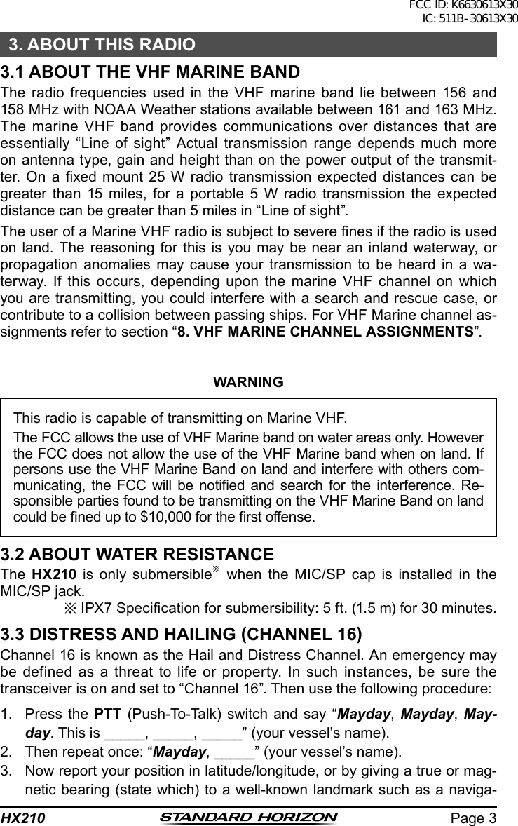
![HX210Page 18Memory Scan (M-SCAN)Scan MemoryChannelScan MemoryChannelScan MemoryChannelScan MemoryChannelPresetChannel 4PresetChannel 5Priority ChannelPresetChannel 0PresetChannel 1PresetChannel 2PresetChannel 3Priority Scan (P-SCAN)6.9.3 OPERATION6.9.3.1 Memory Scanning (M-SCAN)1. Set the scan type to “M-SCAN” in the SETUP menu (refer to “6.9.2 Se-lecting Scan Type”).2. Press the [SQL] switch, then press the [▲]/[▼] key until background noise disappears.3. Press one of soft keys.4. Press the [◄]/[►] key repeatedly, until the [SCAN] soft key is displayed at the bottom of the LCD.5. Press the [SCAN] soft key. “MEM SCAN” appears on the display. Scan-ning will proceed from the lowest to the highest programmed channel number and preset channel (described in the next section) and will stop on a channel when a transmission is received. The channel number will blink during reception.6. To stop scanning, press the [16/S] or [CLR/] key.6.9.3.2 Priority Scanning (P-SCAN)1. Set the scan type to “P-SCAN” in the SETUP menu (refer to “6.9.2 Se-lecting Scan Type”).2. Press the [SQL] switch, then press the [▲]/[▼] key until background noise disappears.3. Press one of soft keys.4. Press the [◄]/[►] key repeatedly, until the [SCAN] soft key is displayed at the bottom of the LCD.5. Press the [SCAN] soft key. “PRI SCAN” appears on the display. Scan-ning will proceed between the memorized channels and preset channel and the priority channel. The priority channel will be scanned after each programmed channel.6. To stop scanning, press the [16/S] or [CLR/ ] key.FCC ID: K6630613X30 IC: 511B-30613X30](https://usermanual.wiki/Yaesu-Musen/30613X30/User-Guide-3494641-Page-20.png)
![Page 19HX2106.10 MULTI WATCH (TO PRIORITY CHANNEL)Multi watch is used to scan two or three channels for communications.m In Dual Watch, a normal VHF channel and the priority channel are scanned alternately.m In Triple Watch, a normal VHF channel, the priority channel, and the sub channel are scanned alternately.When a signal is received on the normal channel the radio briey switches between the normal channel and the priority channel to look for a transmis-sion. If the radio receives communications on the priority channel the radio stops and listens to priority channel until communication ends and then starts dual or triple watch scan again.6.10.1 Setting up the Multi Watch Operation1. Press and hold the [MENU/SET] key.2. Press the [▲]/[▼] key to select “CHANNEL SETUP”.3. Press the [SELECT] soft key, then select “MULTI WATCH” with the [▲]/[▼] key.4. Press the [SELECT] soft key.5. Press the [▲]/[▼] key to select “DUAL” or “TRIPLE”.6. Press the [ENTER] soft key to store the selected setting.7. Press the [CLR/] key to return to radio operation.6.10.2 Starting the Dual Watch1. Press the [SQL] switch, then press the [▲]/[▼] key until background noise disappears.2. Press the [▲]/[▼] key to select a channel you wish to watch.3. Press one of soft keys.4. Press the [◄]/[►] key repeatedly, until the [DW] soft key is displayed at the bottom of the LCD.5. Press the [DW] soft key. The radio will monitor the priority channel and the channel that was selected in step 2.6. If a signal is received on the channel selected in step 2, the HX210 will dual watch to priority channel.7. To stop dual watch, press the [CLR/] key.FCC ID: K6630613X30 IC: 511B-30613X30](https://usermanual.wiki/Yaesu-Musen/30613X30/User-Guide-3494641-Page-21.png)
![HX210Page 206.10.3 Starting the Triple WatchYou may change the Dual Watch feature to Triple Watch via the Menu (“Set”) Mode. The Triple Watch scans Channel 16, 9, and one other channel.1. Press the [▲]/[▼] key to select the channel to scan along with Channel 9 and 16.2. Press one of soft keys.3. Press the [◄]/[►] key repeatedly, until the [TW] soft key is displayed at the bottom of the LCD.4. Press the [TW] soft key to activate the Triple Watch feature.5. When a transmission is received on the channel 16, HX210 will stay on the channel 16 until the incoming signal disappears.6. When a transmission is received on the channel 9, the HX210 will Dual watch between the channel 16 and channel 9.7. When the HX210 receives a transmission on the working channel, the HX210 will Triple watch between the working channel, channel 16, and channel 9.8. To stop Triple watch, press the [CLR/] key.6.11 Listening to the FM RadioThe HX210 includes provision for reception of FM broadcasts.1. Press the [MENU/SET] key to display “MENU”, then press the “RADIO” soft key. The FM broadcast coverage is 76.000 to 108.000 MHz and utilizes Wide-FM mode.2. Press the [▲]/[▼] key to select the desired station.3. To exit from the FM Broadcast Reception mode, press the [MENU/SET] key to display “MENU”, then press the [CH] soft key.6.12 Soft KeysThis menu item allows soft key assignment and how long the display will show the soft key icon after a soft key is pressed.1. Press and hold the [MENU/SET] key.2. Press the [▲]/[▼] key to select “CONFIG”, then press the [SELECT] soft key.3. Select “KEY SETUP” with the [▲]/[▼] key, then press the [SELECT] soft key.4. Select “ASSIGNMENT” with the [▲]/[▼] key, then press the [SELECT] soft key.5. Press the [▲]/[▼] key to select the key number to be programmed, and press the [ENTER] soft key.FCC ID: K6630613X30 IC: 511B-30613X30](https://usermanual.wiki/Yaesu-Musen/30613X30/User-Guide-3494641-Page-22.png)
![Page 21HX2106. Press the [▲]/[▼] key to select a new function to be assigned, and press the [ENTER] soft key. Available functions are listed below.7. Press the [CLR/ ] key to return to radio operation.Display FunctionHI/MD/LO Selects transmit power. DW/TW Turns on or off dual or triple watch scan.MEMORY Add or remove channels from memory channel scan.SCAN Turns on or off scanning function.PRESET Programs or deletes the preset memory channel.STROBE Turns on or off the strobe light LED.6.13 Key Timer1. Press and hold the [MENU/SET] key.2. Press the [▲]/[▼] key to select “CONFIG”, then press the [SELECT] soft key.3. Select “KEY SETUP” with the [▲]/[▼] key, then press the [SELECT] soft key.4. Select “KEY TIMER” with the [▲]/[▼] key, then press the [SELECT] soft key.5. Press the [▲]/[▼] key to select the desired time.6. Press the [ENTER] soft key to store the selected setting.7. Press the [CLR/ ] key to return to radio operation.6.14 ResetYou may initialize the memories and settings of the setup categories inde-pendently or return the transceiver to the original factory setting.1. Press and hold the [MENU/SET] key.2. Press the [▲]/[▼] key to select “CONFIG”, then press the [SELECT] soft key.3. Select “RESET” with the [▲]/[▼] key, then press the [SELECT] soft key.4. Press the [▲]/[▼] key to select the desired category. You can select one from “CHANNEL”, “CONFIG”, or “ALL” (all settings except the MMSI will be initialized).5. Press the [SELECT] soft key.6. Press the [▲]/[▼] key to select “OK?”, then press the [ENTER] soft key.FCC ID: K6630613X30 IC: 511B-30613X30](https://usermanual.wiki/Yaesu-Musen/30613X30/User-Guide-3494641-Page-23.png)
![HX210Page 226.15 Key BeepThis selection is used to select the beep tone volume level when a key is pressed.1. Press and hold the [MENU/SET] key.2. Press the [▲]/[▼] key to select “CONFIG”, then press the [SELECT] soft key.3. Select “KEY BEEP” with the [▲]/[▼] key, then press the [SELECT] soft key.4. Press the [▲]/[▼] key to select the desired level. The beep level can be set from “1” to “5”, or “OFF”.5. Press the [ENTER] soft key to store the selected level.6. To stop Triple watch, press the [CLR/ ] key.6.16 Battery SaverThis function allows you to change the battery save mode setting.1. Press and hold the [MENU/SET] key.2. Press the [▲]/[▼] key to select “CONFIG”, then press the [SELECT] soft key.3. Select “BATTERY SAVE” with the [▲]/[▼] key, then press the [SELECT] soft key.4. Press the [▲]/[▼] key to select the desired setting. You can select one from “OFF”, “50%”, “70%”, “80%”, or “90%”.5. Press the [ENTER] soft key to store the selected level.6. To stop Triple watch, press the [CLR/] key.FCC ID: K6630613X30 IC: 511B-30613X30](https://usermanual.wiki/Yaesu-Musen/30613X30/User-Guide-3494641-Page-24.png)

![Page 33HX21010. SPECIFICATIONSPerformance specications are nominal, unless otherwise indicated, and are subject to change without notice.10.1 GENERALFrequency Ranges: TX: 156.025 MHz - 161.600 MHz RX: 156.050 MHz - 163.275 MHzChannel Spacing: 25 kHzFrequency Stability: ±3 ppm (–4 °F to +140 °F [–20 °C to +60 °C])Emission Type: 16K0G3EAntenna Impedance: 50 Operating Voltage: 7.4 V DCCurrent Consumption: 330 mA (Receive, Typical at AF MAX.) 100 mA (Standby) 1.6 A / 1.0 A / 0.7 A (TX: 6 W / 2.5 W / 1 W)Operating Temperature: –4 °F to +140 °F (–20 °C to +60 °C)Case Size (W x H x D): 2.36” x 5.2” x 1.58” (60 x 132 x 40 mm) (w/o knob & antenna)Weight (Approx.): 9.9 oz (280 g) (with Belt Clip, & Antenna)10.2 TRANSMITTERRF Power Output: 6 W / 2.5 W / 1 W (@3.7 V )Maximum Deviation: ±5 kHzSpurious Emission: Less than 0.25 µWMicrophone Impedance: 2 k10.3 RECEIVERCircuit Type: Double-Conversion SuperheterodyneIntermediate Frequencies: 1st: 51.650 MHz, 2nd: 450 kHzAdjacent Channel Selectivity: 70 dB typicalIntermodulation: 68 dB typicalHum & Noise Ratio: 40 dB typicalSensitivity (12 dB SINAD): 0.25 µV (-6 dBµVemf)Selectivity: 25 kHz (–60 dB)AF Output (Internal SP): 600 mW @16 for 10 % THD (@ 7.4 V)FCC ID: K6630613X30 IC: 511B-30613X30](https://usermanual.wiki/Yaesu-Musen/30613X30/User-Guide-3494641-Page-35.png)