Yaesu Musen FT-1500M VHF Amateur Scanning Receiver User Manual K66FT 1500M OperatingManual
Yaesu Musen Co., Ltd. VHF Amateur Scanning Receiver K66FT 1500M OperatingManual
UserManual.wiki
>
Yaesu Musen
>
FT 1500M User Manual
Manual
Navigation menu
Upload a User Manual
Namespaces
Wiki Guide
HTML
PDF
Info
Views
User Manual
Discussion / Help
Navigation
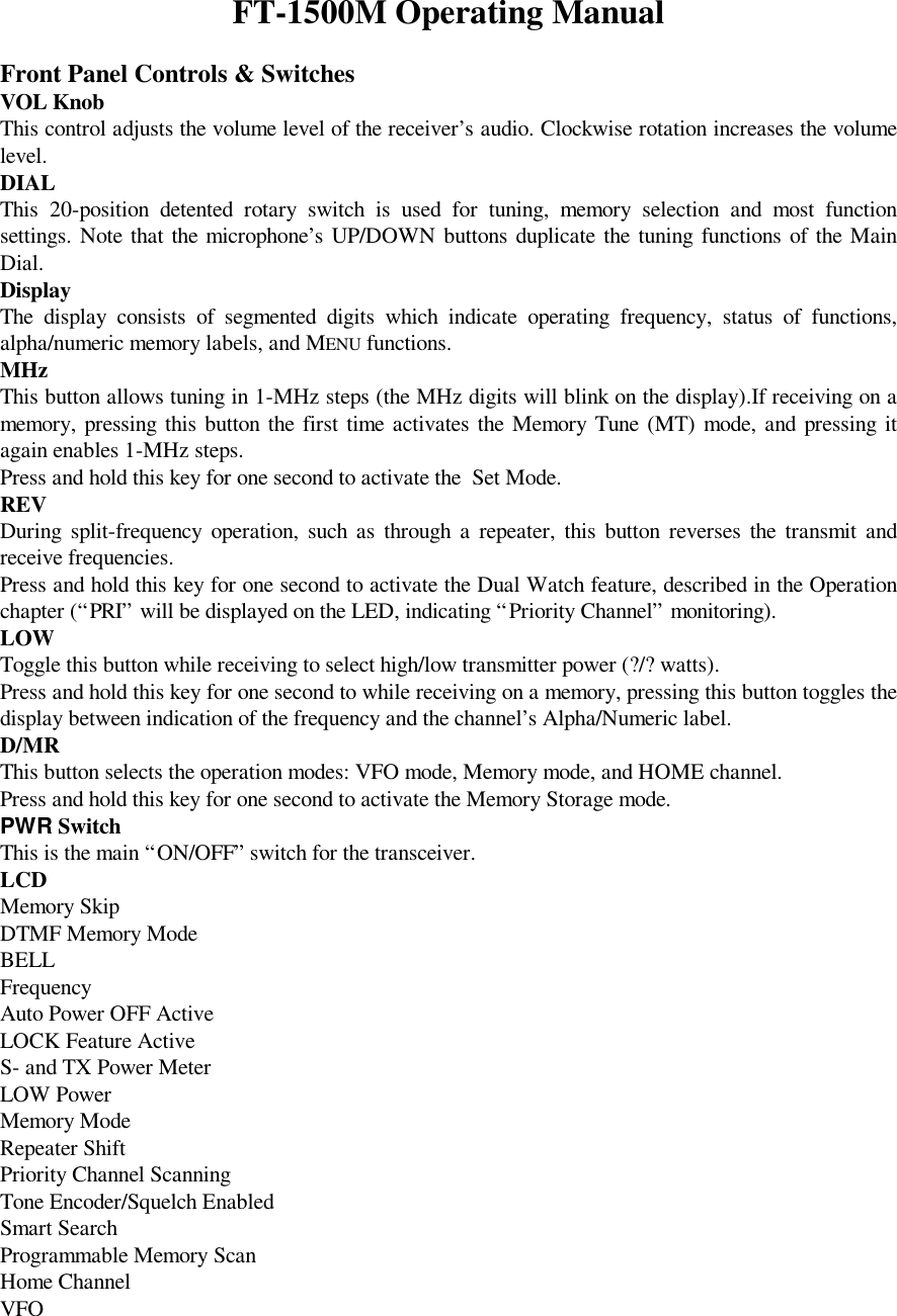
![Burst tone produced by the MH-???? microphone.Typical connections to a TNC are shown below.1200 bps Packet Setup9600 bps Packet SetupFinally, note that Menu (“PCKT”) allows you to enable or disable the microphone during packetoperation. Normally, the default setting (“Microphone Disabled during Packet TX”) is appropriate;when the microprocessor detects PTT input from the Data connector, the microphone will be disabled.Basic OperationPower On and OffPress the PWR switch momentarily to turn the radio on.To turn the radio off, press and hold in the PWR switch for one second.Adjusting the Volume LevelRotate the VOL control to adjust the receiver volume. Clockwise rotation increases the audio outputlevel.Squelch SetupThe Squelch system is designed to keep the receiver quiet until a signal is received. The Squelchshould be adjusted to the point where the background noise is just silenced; any “higher” setting willreduce the receiver’s sensitivity to weak signals.To adjust the setting of the Squelch system:1. Rotate the Main Dial to select a clear frequency (where no signals are present).2. Press and hold in the [MHz] key for one second, then rotate the Main Dial knob to select “SQL.”3. Press the [MHz] key momentarily, then rotate the Main Dial knob to select the squelch thresholdlevel (OFF, or 1 to 15). While you are making this adjustment, you will be able to hear thebackground noise appear when the Squelch setting is too low. The best sensitivity will be realizedwhen the Squelch is set to one number past the point where noise is muted.4. Press and hold in the [MHz] key for one second to save the new setting and exit to normaloperation.TransmittingTo transmit, simply close the PTT (Push To Talk) switch on the microphone when the frequency isclear. Hold the microphone approximately 25 mm (1”) from your mouth, and speak into themicrophone in a normal voice level. When your transmission is complete, release the PTT switch; thetransceiver will revert to the receive mode.Tuning: The “DIAL” (VFO) ModeThis mode is used for selecting a frequency utilizing the Main Dial knob and microphone [UP] and[DWN] buttons allow the Variable Frequency Oscillator (VFO) to tune in the selected step size. Whenscanning in the VFO mode, the same steps are used as in manual tuning.Clockwise rotation of the Main Dial knob increases the operating frequency, while counter-clockwiserotation tunes toward a lower frequency.To move frequency rapidly (in 1 MHz steps), press the [MHz] key momentarily, then rotate the MainDial knob. The 1 MHz digit of the frequency display will blink while “1 MHz Tuning” is enabled.When you have selected the desired “1 MHz” frequency digit, press the [MHz] key momentarily oncemore, then resume normal tuning using the Main Dial knob.Direct Keypad Frequency EntryThe keypad of the MH-?? DTMF Microphone may be used for direct entry of the operating frequency.It also may be used for recall of memory channels.](https://usermanual.wiki/Yaesu-Musen/FT-1500M/User-Guide-78533-Page-6.png)
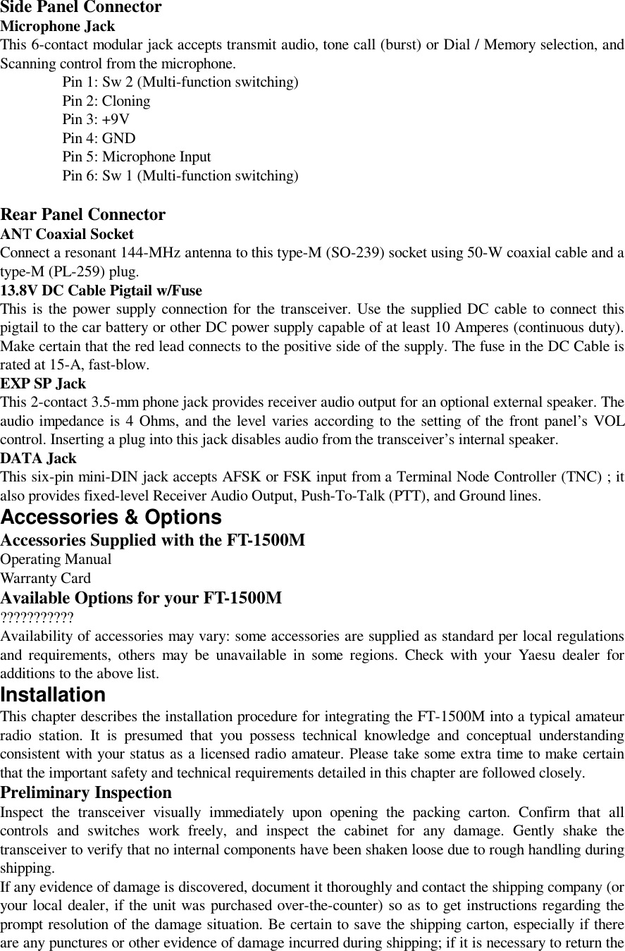
![To enter a frequency from the MH-?? keypad:1. Press the [D/MR] key, if necessary, to set the transceiver into the VFO mode.2. While receiving on any VFO frequency, enter the digits of the desired frequency. For example, to enter 146.520 MHz, press [1]–[4]–[6]–[5]–[2]–[0]. A high-pitched “beep” will confirm each key closure as you enter the digits; the final “beep” willbe of longer duration, to confirm that the frequency entry is complete.3. The [#] key may be used to abbreviate the entry procedure. Pressing the [#] key sets the currentdigit and all following digits to “0” to complete the entry.For example, to enter 146.500 MHz, press [1]–[4]–[6]–[5]–[#].To enter 144.000 MHz, press [1]–[4]–[4]–[#].Recalling memories is equally simple (see page ?? for details on memory operation). You can recall amemory from the MH-?? from any operating mode: VFO, Home, or Memory.1. Press the Channel Number you wish to recall, then press the [*] key. For example, to recallMemory Channel 2, press [2]–[*]. To recall Channel number 135, press [1]–[3]–[5]–[*].2. To return to the VFO mode, press the front panel’s [D/MR] key or the microphone's [D] key.3. If you are in the Memory Recall mode, you can enter a new operating frequency directly, asdescribed above for VFO operation. However, you will observe that a “MR” indicator will beblinking appear at the left side of the display; this indicates that you have switched to the “MemoryTune” mode, which is described in detail on page ??.Changing the Transmitter Power LevelFour power output levels are available on this transceiver: 5 watts (Low 3), 10 watts (Low 2), 25watts (Low 1) and 50 watts (High).To change the power level, press the [REV] key to select one of four power setting. These powerlevels will be stored in memory registers, at the time of memory storage (see page ?? for details onMemory operation).During transmission, the Bar Graph will deflect in the display, according to the power output selected.Transmitter Thermal Protection SensorChanging the Channel StepsTuning steps are factory preset to default increments which are appropriate for the country to whichthis radio is exported.To change to another step size, use the following procedure:1. Press and hold the [MHz] key for one second, then rotate the Main Dial knob to select “STEP.”2. Press the [MHz] key, then rotate the Main Dial knob to select the desired step size:5.0/10.0/12.5/15.0/20.0/25.0/50.0 (kHz).3. Press and hold in the [MHz] key for one second to save the new setting and exit to normaloperation.Keyboard LockingIn order to prevent accidental frequency change or inadvertent transmission, various aspects of the FT-1500M’s keys and switches may be locked out. The possible lockout combinations are:KEY:Just the front panel keys are locked outDIAL: Just the front panel DIAL is locked outK + D (KEY + DIAL) : Both the DIAL and Keys are locked outPTT: The PTT switch is locked (TX not possible)K + P (KEY + PTT) : Both the keys and PTT switch are locked outD + P (DIAL + PTT) : Both the DIAL and PTT switch are locked outALL: All of the above are locked outTo lock out some or all of the keys:1. Press and hold in the [MHz] key for one second, then rotate the Main Dial knob to select“LOCK.”](https://usermanual.wiki/Yaesu-Musen/FT-1500M/User-Guide-78533-Page-7.png)
![2. Press the [MHz] key, then rotate the Main Dial knob to choose between one of the lockingschemes as outlined above.3. Press and hold in the [MHz] key for one second to save the new setting and exit to normaloperation.Repeater OperationThe FT-1500M includes a host of convenience features which makes operation on amateur repeatersboth efficient and enjoyable.Repeater SplitsThis transceiver offers three methods of setting up split-frequency operation on repeaters:[1] Manual selection of preset repeater shifts;[2] Automatic Repeater Shift (ARS), providing automatic activation of repeater shifts withindesignated repeater frequency subbands; and[3] Independently stored transmit and receive frequencies (typically not corresponding to establishedrepeater frequency shifts).[1] Standard Repeater ShiftsThe FT-1500M has been shipped ready for use on the repeater shift typically used in your country. Forcustomers in the United States, for example, the standard repeater shift will be 600 kHz, and thedirection of the shift will depend on the part of the band in which you are operating.To activate the standard shift manually:1. Press and hold in the [MHz] key for one second, then rotate the Main Dial knob to select“RPTR.”2. Press the [MHz] key, then rotate the Main Dial knob to select the desired shift direction: ARS(Automatic Repeater Shift), SHIFT– , SHIFT+, or OFF (Simplex).3. Press and hold in the [MHz] key for one second to save the new setting and exit to normaloperation.With repeater shift activated, you can temporarily reverse the transmit and receive frequencies bypressing the front panel's [REV] key. Use this feature to display the transmit frequency withouttransmitting, and to check the strength of signals on a repeater uplink frequency (so as to determinewhether or not a particular station is within “Simplex” range, for example).Changing the Default Repeater ShiftThe repeater offset is usually set to 600 kHz from the factory. You can change the offset by usingfollowing procedure, if needed:1. Press and hold in the [MHz] key for one second, then rotate the Main Dial knob to select“SHIFT.”2. Press the [MHz] key, then rotate the Main Dial knob to set the desired offset. Note that theresolution of the “standard” repeater shift is to the nearest 50 kHz multiple.3. Press and hold in the [MHz] key for one second to save the new setting and exit to normaloperation.Note: Do not use the above procedure if you just want to operate on one “odd split” frequency.Use the “Independent Transmit/Receive Frequency” mode, as described in section [3] on the nextpage.[2] Automatic Repeater ShiftThe ARS (Automatic Repeater Shift) feature in the FT-1500M allows easy and convenient repeateroperation by automatically activating the repeater shift function whenever you tune to a standardrepeater sub-band. The ARS function is preset at the factory to conform to the standards for thecountry to which it is exported.The ARS function is enabled at the factory. To disable it:1. Press and hold in the [MHz] key for one second, then rotate the Main Dial knob to select “ARS.”2. Press the [MHz] key, then rotate the Main Dial knob to change the display to “OFF.”](https://usermanual.wiki/Yaesu-Musen/FT-1500M/User-Guide-78533-Page-8.png)
![3. Press and hold in the [MHz] key for one second to save the new setting and exit to normaloperation.To enable the ARS function again, select “ON” in step (2) above.[3] Separate Transmit Frequency MemoriesAll memory channels can store independent receive and transmit frequencies, to accommodateoccasional non-standard offsets with greater frequency resolution than is available using the“standard” shift feature.Here is the procedure for storing an “odd split” frequency pair into a memory. A full discussion ofmemory channel storage and recall is found in the next section.1. First store the receive (repeater output) frequency. In the VFO mode, tune the transceiver to thedesired receive frequency. Now press and hold in the [D/MR] key for one second.2. Within five seconds of pressing the [D/MR] key, use the Main Dial knob (or the microphone’s[UP]/[DWN] buttons) to select the memory channel number on which you wish to store thefrequency pair. If the memory register already has data stored in it, the display will blink“CHnnnUSD” where “nnn” is the channel number.3. Now press the [D/MR] key for one second to store the receive frequency into the selectedmemory.4. Next, store the transmit (repeater input) frequency. Since you are still in the VFO mode, tune thetransceiver to the desired transmit frequency.5. Now press and hold in the [D/MR] key for one second.6. Press and hold the PTT switch, then press the [D/MR] key while holding in the PTT switch. Thiswill not cause transmission, but rather it will instruct the transceiver that you are programming aseparate transmit frequency into memory.When you have finished the above procedure, press the [D/MR] key momentarily. The channelnumber will flash onto the display momentarily, to be followed by the repeater downlink frequency. Ifyou press the PTT switch, you will observe the display changing to indicate the repeater's uplinkfrequency. Note also that the display shows “– +” in the upper left-hand corner; this indicates that an“odd” (non-standard) shift has been stored on this channel.Advanced OperationSupply Voltage DisplayWhen you turn on the radio, the current DC supply voltage will be indicated on the display for 2.5second. After this interval, the display will resume its normal indication of the operating frequency.To view the supply voltage at any time during operation, use the following procedure:1. Press and hold the [MHz] key for one second, then rotate the Main Dial knob to select “DC IN.”2. Press the [MHz] key momentarily to display the current DC supply voltage on the LCD.3. Press and hold in the [MHz] key for one second to exit to normal operation.Keypad BeeperA key/button beeper provides useful audible feedback whenever a button is pressed. Each key andbutton has a different beep pitch, and each function has a unique beep combination.If you want to turn the beeper off (or back on again):1. Press and hold in the [MHz] key for one second, then rotate the Main Dial knob to select “BEEP.”2. Press the [MHz] key, then rotate the Main Dial knob to select the display to “OFF.”3. Press and hold the [MHz] key for one second to save the new setting and exit to normal operation.Display BrightnessThe FT-1500M display illumination has been specially engineered to provide high visibility withminimal disruption of your “night vision” while you are driving. The brightness of the display ismanually adjustable, using the following procedure:1. Press and hold in the [MHz] key for one second, then rotate the Main Dial knob to select“DIMR.”2. Press the [MHz] key, then rotate the Main Dial knob. You will observe the brightness of thedisplay changing.](https://usermanual.wiki/Yaesu-Musen/FT-1500M/User-Guide-78533-Page-9.png)
![3. Press and hold in the [MHz] key for one second to save the new setting and exit to normaloperation.RF SquelchA special “RF Squelch” feature is provided on this radio. This feature allows you to set the squelch sothat only signals exceeding a certain S-meter level will open the squelch.To set up the RF squelch circuit for operation, use the following procedure:1. Press and hold in the [MHz] key for one second, then rotate the Main Dial knob to select“RFSQL.”2. Press the [MHz] key momentarily, then rotate the Main Dial knob to select the desired signalstrength level for the squelch threshold (OFF, or S-1 to S-10).3. Press and hold in the [MHz] key for one second to save the new setting and exit to normaloperation.Note: The receiver’s squelch will open based on the highest level set by the two squelch systems(Noise Squelch and RF Squelch). For example:1. If the Noise Squelch (Menu #29) is set so that signals at a level of S-3 will open the squelch, butthe RF Squelch (Menu #23) is set to “S-9,” the squelch will only open on signals which are S-9or stronger on the S-meter.2. If the RF Squelch is set to “S-3,” but the Noise Squelch is set to a high level which will onlypass signals which are Full Scale on the S-meter, the squelch will only open on signals which areFull Scale on the S-meter. In this case, the Noise Squelch overrides the action of the RF Squelch.Automatic Power-Off (APO) FeatureThe “Automatic Power-Off” (APO) feature will turn the radio completely off after a user-definedperiod of PTT or key/button inactivity. If you do not press any front panel keys or buttons, rotate theMain Dial knob, use the microphone’s keys and buttons, or transmit, and so long as the transceiver isnot scanning or engaged in priority monitoring, the radio will shut itself off after the specified timeperiod. This feature is useful in minimizing battery drain in a mobile installation if you forget to turnthe transceiver off when you leave your vehicle.To activate the APO feature as follows:1. Press and hold in the [MHz] key for one second, then rotate the Main Dial knob to select “APO.”2. Press the [MHz] key, then rotate the Main Dial knob to select the desired “switch-off” time(between 1 and 12 hours, or OFF).3. Press and hold in the [MHz] key for one second to save the new setting and exit to normaloperation.Transmitter Time-Out Timer (TOT)The “Time-Out Timer” (TOT) feature is designed to force the transceiver into the “receive” modeafter a preset time period of continuous transmission (the default is 6 minutes). This feature preventsyour transceiver from transmitting a “dead carrier” for a long period of time in the event that themicrophone PTT switch is accidentally locked in the “TX” condition.The Time-Out Timer’s “switch-to-receive” time may be adjusted, in one minute increments, for anyperiod between 1 and 60 minutes.To change the default (6 minute) time setting as follows:1. Press and hold in the [MHz] key for one second, then rotate the Main Dial knob to select “TOT.”2. Press the [MHz] key, then rotate the Main Dial knob to select the desired time interval (between 1and 60 minutes, or OFF).3. Press and hold in the [MHz] key for one second to save the new setting and exit to normaloperation.Programmable Microphone Keys (P1/P2/P3/P4)Default FT-1500M key functions have been assigned (at the factory) to the microphone’s [P1], [P2],[P3], and [P4] buttons. These may be changed by the user, if you wish to define another function for aparticular key or keys.](https://usermanual.wiki/Yaesu-Musen/FT-1500M/User-Guide-78533-Page-10.png)
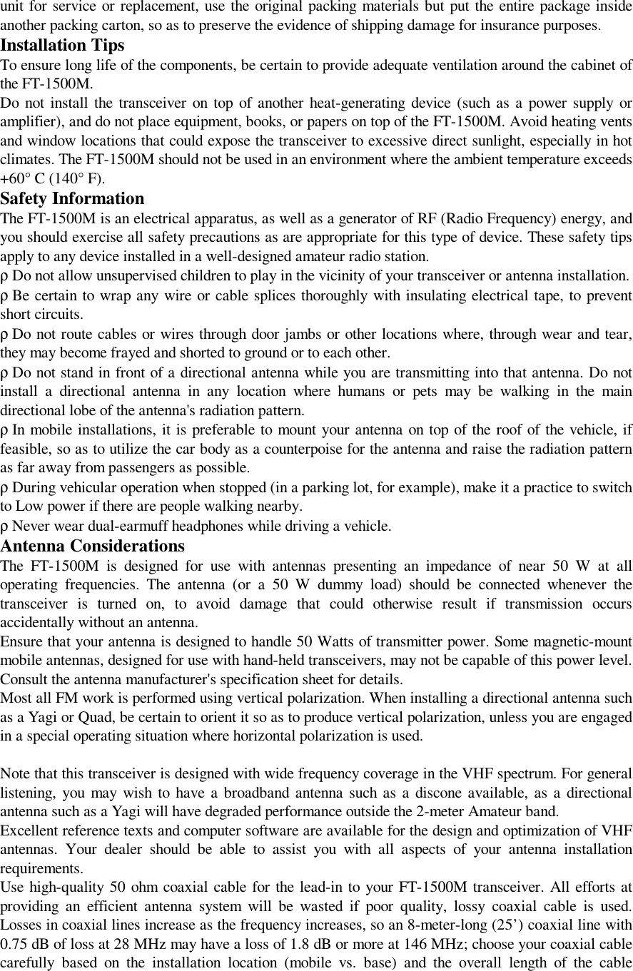
![To change the assignment of a key's function:1. Press and hold in the [MHz] key for one second, then rotate the Main Dial knob to the Menu Item# corresponding to the key to be assigned a function (18 PRG P1, 19 PRG P2, 20 PRG P3, or 21PRG P4).2. Press the [MHz] key momentarily, then rotate the Main Dial knob to select the function you wishto assign to the key or button you selected in the previous step. The available choices are: MON Opens the Squelch to allow un-muted reception. S. SRCH Initiates Smart Search scanning. T. SRCH Initiates scanning for (unknown) CTCSS tone. WX ?? SQ. TYP Selects CTCSS mode and frequency. T. CALL Activates 1750 Hz Tone Burst. SHIFT Selects Repeater Shift direction. TX POWER Allows setting of the transmitter power level. AN ??3. Press the [MHz] key momentarily to lock in the new setting.4. Rotate the Main Dial knob to select another programmable key or button to modify, if desired,from the remaining Menu items. Follow the procedure outlined above.5. Press and hold in the [MHz] key for one second to save the new setting and exit to normaloperation.Tone Calling (1750 Hz)If you own a non-European version of the FT-1500M, but plan on visiting a country which requires a1750 Hz tone for repeater access, you may set up the Programmable key for 1750 Hz Tone operation.See page ?? for details.Weather Broadcast ReceptionThe FT-1500M includes a unique feature which allows reception of weather broadcasts in the 160-MHz frequency range. Ten standard Weather Broadcast channels are pre-loaded into a specialmemory bank.To listen to a Weather Broadcast Channel:1. Press the [P4] key to recall the Weather Broadcast channels.2. Turn the Main Dial knob to select the desired Weather Broadcast channel.3. If you wish to check the other channels for activity by scanning, just press and hold the [UP] or[DWN] key for one second, or press the PTT switch.4. To exit to normal operation, again press the [P4] key. Operation will return to the VFO orMemory channel you were operating on before you began Weather Broadcast operation.You can also append an alpha-numeric “Tag” (label) to a Weather Broadcast channel. See page ??.Channel Frequency Channel Frequency Channel FrequencyWX 1 162.550MHz WX 5 162.450 MHz WX 9 161.775 MHzWX 2 162.400 MHz WX 6 162.500 MHz WX 10 163.275 MHzWX 3 162.475 MHz WX 7 162.525 MHzWX 4 162.425 MHz WX 8 161.650 MHzTone Squelch ModesRepeater systems often require an access signal for activation of the repeater. These access tones areoften required so as to reduce false activation of the repeater by random noises or other signals on theband. Additionally, these systems can allow silent monitoring of busy channels until a call directed toyour radio is received, offering less disruption to family activities, etc.CTCSS (Continuous Tone Coded Squelch System)This system superimposes a continuous, subaudible tone on your transmitted audio. When decoded atthe other station, the CTCSS signal triggers their squelch to open and receive your transmission. Some“closed” repeaters use this to limit access, or to prevent signals intended for other repeaters (with the](https://usermanual.wiki/Yaesu-Musen/FT-1500M/User-Guide-78533-Page-11.png)
![same input frequency) in fringe areas from locking up the repeater. There are 47 selectable CTCSStones provided in the FT-1500M.To use CTCSS, both stations must be on the same frequency, and must have selected the same CTCSStone.To select and activate CTCSS operation:1. Press and hold in the [MHz] key for one second, then rotate the Main Dial knob to select“TONE.”2. Press the [MHz] key, then rotate the Main Dial knob to select the desired squelch type from thefollowing: µ “ENC”(Encode) appears when the CTCSS tone generator is activated for transmission only. µ “ENC/DEC” (Encode/Decode) appears when the CTCSS Tone Squelch is activated for both TXand RX (only signals “Encoded” with the matching tone will open your radio’s squelch).3. Press and hold in the [MHz] key for one second to save the new setting and exit to normaloperation.Now that you have selected the Tone Mode to be used, you need to select the CTCSS tone, that youand the other station have both agreed to use:1. Press and hold in the [MHz] key for one second, then rotate the Main Dial knob to select “TNFRQ.”2. Press the [MHz] key, then rotate the Main Dial knob to choose the desired CTCSS tone.3. Press and hold in the [MHz] key for one second to save the new setting and exit to normaloperation.CTCSS settings may stored in any memory register at the time of frequency programming. To changea memorized tone or tone system, just recall the memory channel, reset the tone or function, and storethe memory again. If you activate CTCSS on a PMS memory, it will be active when that memory pairis used to start PMS scanning or tuning.Tone Search ScanningIn operating situations where you don’t know the CTCSS tone being used by another station, you cancommand the radio to listen to the incoming signal and scan in search of the tone being used.Before you begin the tone search, please check the (programmable) setting of the microphone’s [P3]button (Menu #20); it should be set to “T.SRCH” for proper operation.To scan for the CTCSS tone in use:1. Set the radio up for the CTCSS operation.2. Press the [P3] button on the microphone momentarily to start scanning for the incoming CTCSStone.3. When the radio detects the correct tone, it will halt on that tone, and audio will be allowed to pass.4. Press and hold in the [D/MR] key for one second; the CTCSS tone detected will be stored as the“current” tone, so it may be used for memory storage purposes. It can be viewed by accessing Menu #33 (TN FRQ).5. Press and hold in the [MHz] key for one second to exit to normal operation.CTCSS Bell OperationCTCSS Bell Paging adds an alert ringer to CTCSS tone squelch operation, for added convenience.When you receive a call with a matching CTCSS tone, the ringer will sound to alert you to thepresence of the incoming call.1. Press and hold in the [MHz] key for one second, then rotate the Main Dial knob to select“BELL.”2. Press the [MHz] key, then rotate the Main Dial knob to change the display to “ON.”3. To de-activate CTCSS Bell operation, select “OFF” in step 2 above.Calls without a matching CTCSS tone will be ignored during CTCSS Bell operation.Note that other stations do not need to have the CTCSS Bell function to call you; they can just use](https://usermanual.wiki/Yaesu-Musen/FT-1500M/User-Guide-78533-Page-12.png)
![standard CTCSS encoding.When you reply to a CTCSS Bell call, you may want to turn off the Bell function, or else thetransceiver will ring every time your squelch opens.You can store the CTCSS Bell Paging function into a memory, along with the CTCSS tone andencode/decode state.Memory OperationThe FT-1500M provides a wide variety of memory system resources. These include:µ 120 “Standard” memory channels, numbered “1” through “120.”µ A Home channel, allowing storage and quick recall of one prime frequency.µ Nine sets of band-edge memories also known as “Programming Memory Scan” channels, labeled“L1/U1” through “L9/U9”.Memory StorageTo store a frequency into memory:1. In the VFO mode, select the desired frequency, repeater shift, CTCSS tone, and TX power level.2. Press and hold in the [D/MR] key for one second. A memory number (or letters and numbers) willappear (blinking) on the display.3. Within five seconds of pressing the [D/MR] key, use the Main Dial knob or the microphone’s[UP]/[DWN] buttons to select the desired memory for storage. If you see an Asterisk (*) by anychannel number, it means that the channel currently has no data written on it (i.e the channel is“free”).4. Press the [D/MR] key again, this time momentarily, to store the displayed data into the selectedmemory channel slot. The memory label will stop blinking, and the display will now be blank,except for a blinking digit at the left side of the display. If you wish to append a name to the just-memorized channel, move quickly to the next step.Note: If the left digit quits blinking, this indicates that the Alpha-Numeric Storage Timer hasexpired. The frequency data will not be lost if this happens, however.Labeling Memories1. While the right-most digit is still blinking in step (4) above, rotate the Main Dial knob to selectthe first character in the name you wish to store, then press the [D/MR] key to move on to the nextcharacter. Letters (both upper and lower case), numbers, and symbols are available for storage.2. Again rotate the Main Dial knob to select the desired number, letter, or symbol, then press the[D/MR] key to move on to the next character’s slot.3. Repeat step (2) as many times as necessary to complete the name tag for the memory, then pressand hold in the [D/MR] key for one second to save the A/N (Alpha-Numeric) name entry and exitto normal operation.Note: If you wish to append a label to a memory after the Alpha-Numeric Storage Timer hasexpired, first recall the memory channel (see below), then press the [MHz] key for one second to enterthe Menu mode. Rotate the Main Dial to select Menu item #01 (ALPH), then press the [MHz] keymomentarily. You will now be ready to begin with step 1 above.Memory RecallFrom the VFO mode, momentarily press the [D/MR] key once to activate the “MR” (Memory Recall)mode.When more than one memory has been stored, use the Main Dial knob to select a memory foroperation. Alternatively, microphone’s [UP] and [DWN] buttons may be used to step or scan throughthe available memories. When using the microphone's buttons, press and immediately release thebutton to move one step up or down; press and hold the [UP] or [DWN] button for one second to beginmemory scanning.While you are operating in the MR mode, the “MR” notation will appear at the left side of the display.Memory Recall from MH-?? MicrophoneWhile operating in the VFO, Home Channel (see below), or Memory Recall mode, the keypad of the](https://usermanual.wiki/Yaesu-Musen/FT-1500M/User-Guide-78533-Page-13.png)
![MH-?? may be used for direct recall of memory channels.To do this, press the Channel Number you wish to recall, then press the [*] key. For example, to recallMemory Channel 5, press [5]–[*]. To recall Channel number 118, press [1]–[1]–[8]–[*].To Turn on the Alpha-Numeric Memory Name DisplayIf you are in the “MR” mode, press and hold the [A/N] key for one second, to replace the frequencydisplay with the Alpha-Numeric Label.HOME Channel MemoryA convenient one-touch “Home” channel memory is available to simplify return to your most-often-used frequency. This memory does not appear in the regular memory bank, to simplify operation.To recall the Home channel while in the MR mode, just press the [D/MR] key momentarily. From theVFO mode, press [D/MR] twice. While you are operating on the Home channel, an “HM” will appearat the right side of the display.The factory default frequency for the Home channel is 146.520 MHz. You can re-program the Homechannel in a manner identical to that used for the regular memories:1. From the VFO mode, tune in the frequency you wish to store, and set all repeater shifts and otherdata just the way you do for “normal” memory channel storage.2. Press and hold the [D/MR] key for one second, then rotate the Main Dial knob to select“HOME.”3. Press the [D/MR] key momentarily to store the new Home channel.4. At this point, the right-most digit will be blinking, as a reminder that you can store an Alpha-Numeric label to the Home channel. Use the A/N storage procedure described previously.Memory Offset TuningOnce you have recalled a particular memory channel, you may tune off that channel, as though youwere in the VFO mode.1. With the FT-1500M in the “MR” mode, select the desired memory channel.2. Press the [MHz] key momentarily.3. Now rotate the Main Dial knob, as desired, to tune to a new frequency. This new frequency maybe stored in a new memory register, if you like, using the procedures described earlier.4. If you wish to return to the original memory frequency, press the [D/MR] key momentarily. Anyoffset tuning will be discarded, and the original memory contents will appear on the display.Masking MemoriesWith 138 total memories available, there frequently are situations where you may desire to “Mask”certain memorized frequencies. The procedure for deleting a channel is quite simple:1. Press and hold in the [D/MR] key for one second.2. Rotate the Main Dial to select the channel to be “Masked”. Note that Memory Channel 1 may notbe deleted, as it is the Priority Channel.3. Press the [LOW] button. This will cause the display to shift to Memory Channel 1, and thepreviously-selected memory will be deleted.4. To Unmask the hidden memory, repeat the above procedure: press and hold in the [D/MR] key forone second, rotate the Main Dial to select the masked memory's number, then press [LOW] torestore the memory channel’s data.Memory Only ModeOnce memory channel programming has been completed, you may place the radio in a “Memory-Only” mode, whereby VFO and Home channel operation are impossible. This may be particularlyuseful during public-service events where a number of operators may be using the radio for first time,and ultimate simplicity of channel selection is desired.To place the radio into the Memory-Only mode, turn it off. Now press and hold in the [D/MR] keywhile turning the radio on. The VFO and Home channel will now be disabled.To return to normal operation, repeat the above power-on procedure.](https://usermanual.wiki/Yaesu-Musen/FT-1500M/User-Guide-78533-Page-14.png)
![ScanningThe FT-1500M’s scanning capability provides the operator with many convenient methods of rapidfrequency navigation.Basic Scanner OperationBefore activating the scanner, make sure that the Squelch is set to silence the background noise whenno signal is present. If noise is being heard, the scanner will not function (because the radio will“think” that it is on a “Busy” channel).Scanning may be started or stopped using the microphone’s [UP] and [DWN] buttons. The followingtechniques are used during scanning operation:1. Pressing and holding in either the [UP] or [DWN] button for one second in the VFO mode willcause upward or downward band scanning, respectively, to begin.2. Pressing and holding in either the [UP] or [DWN] button for one second in the Memory Recallmode will cause memory channel scanning toward a higher- or lower-numbered memory channel,respectively.3. Scanning pauses when a signal opens the squelch, and the decimal point on the display will blink.You can choose one of two scan-resume modes (described later).4. To halt the scan manually, the easiest way is to push the PTT switch on the microphonemomentarily (no transmission will occur while you are scanning).The scan may also be halted manually by pressing the microphone’s [UP] or [DWN] button, or the[D/MR] key on the front panel of the radio.Scan-Resume OptionsThree scan-resume modes are available on the FT-1500M:BUSY: In this mode, the scanner will remain halted for as long as there is carrier present onthe channel; after the carrier drops at the end of the other station’s transmission, the scannerwill resume.5SEC: In this mode, the scanner will halt for five seconds only, after which scanning willresume (whether or not the other station is still transmitting).HOLD: In this mode, the scanner will halt on a signal it encounters. It will not restartautomatically; you must manually re-initiate scanning if you wish to resume.To change the scan-resume mode:1. Press and hold in the [MHz] key for one second, then rotate the Main Dial knob to select“SCAN.”2. Press the [MHz] key, then rotate the Main Dial knob to select the desired scan-resume mode(BUSY, 5SEC, or HOLD).3. Press and hold in the [MHz] key for one second to save the new setting and exit to normaloperation.Memory Skip Scanning (MR Mode)When you have some continuously-active channels (like Weather broadcasts) in memories, you maywish to skip them for scanning, but still have them available for manual selection.To select a memory to be skipped during scanning:1. Recall the memory channel to be skipped. Note that Memory Channel 1 may not be skipped, as itis the Priority Channel.2. Press and hold in the [MHz] key for one second, then rotate the Main Dial knob to select “SKIP.”3. Press the [MHz] key, then rotate the Main Dial knob to select “SKIP.”4. Press and hold in the [MHz] key for one second to save the new setting and exit to normaloperation.To re-enable a “Skipped” memory channel, select “STOP” in step (3) above.Temporary Memory SkipIf the scanner repeatedly stops on a channel due to temporary noise or interference, you cantemporarily mark it to be skipped. The channel will be skipped until you manually stop the scan (by](https://usermanual.wiki/Yaesu-Musen/FT-1500M/User-Guide-78533-Page-15.png)
![pressing the PTT switch, for example).To skip a channel temporarily, press the [MHz] key momentarily while the scanner has stopped on thechannel to be skipped. The scanner will instantaneously resume, and that channel will not be scannedduring this scanning session. Note that Memory Channel 1 may not be skipped, as it is the PriorityChannel.Programmable (Band Limit) Memory Scan (PMS)This feature allows you to set sub-band limits for either scanning or manual VFO operation. Forexample, you might wish to set up a limit (in North America) of 144.300 MHz to 148.000 MHz so asto prevent encroachment into the SSB/CW “Weak Signal” portion of the band below 144.300 MHz.Here’s how to do this:1. Using the techniques learned earlier, store (per the above example) 144.300 MHz into MemoryChannel #L1 (the “L” designates the Lower sub-band limit).2. Likewise, store 148.000 MHz into Memory Channel #U1 (the “U” designates the Upper sub-bandlimit).3. With any of these memories recalled, press the [MHz] key momentarily to activate theProgrammable Band-Scan Limits. The “PMS” notation will appear at the left side of the display,reminding you that you are using the Programmable Band Limits.The frequencies stored in memories “L” and “U” will now serve as tuning and scanning limits, thuscreating a tuning sub-band.To cancel the sub-band limits and return to normal memory operation, press the [D/MR] keymomentarily.Note:µ If the frequency in memory channel “Lx” is equal to or greater than the frequency stored in memorychannel “Ux,” you can not activate the PMS operation.µ Nine pairs of Band Limit memories, labeled L1/U1 through L9/U9 are available.Band Edge BeeperSmart Search OperationThe Smart Search feature allows you to load frequencies automatically according to where activity isencountered by your radio. When Smart Search is engaged, the transceiver will search above andbelow your current frequency, storing active frequencies as it goes (without stopping on them evenmomentarily); these frequencies are stored into a special Smart Search memory bank, consisting of 31memories (15 above the current frequency, 15 below the current frequency, plus the current frequencyitself).Two basic operating modes for Smart Search are available:SINGLE: In this mode, the transceiver will sweep the current band once in each direction starting onthe current frequency. All channels where activity is present will be loaded into the Smart Searchmemories; whether or not all 31 memories are filled, the search will stop after one sweep in eachdirection.CONTINUE: In this mode, the transceiver will make one pass in each direction as with One-Shot searching; if all 31 channels are not filled after the first sweep, however, the radio will continuesweeping until they are all filled.Setting the Smart Search Mode1. Press and hold in the [MHz] key for one second, then rotate the Main Dial knob to select“S.SRCH.”2. Press the [MHz] key, then rotate the Main Dial knob to select the desired Smart Search mode (seeabove).3. Press and hold in the [MHz] key for one second to save the new setting and exit to normaloperation.](https://usermanual.wiki/Yaesu-Musen/FT-1500M/User-Guide-78533-Page-16.png)
![Storing Smart Search Memories1. Press the [P2] key.*2. The Smart Search process will now cause the radio to scan upward on current band, loadingchannels on which it encounters a signal strong enough to open the squelch.3. Depending on the mode you set for Smart Search operation (SINGLE or CONTINUE), the SmartSearch scan will eventually terminate, and the LCD will revert to Smart Search Memory Channel0.4. To recall the Smart Search Memories just stored, rotate the Main Dial knob or press themicrophone’s [UP] or [DWN] key.5. If you find particular channels which you wish to store into the “regular” memory system, followthe memory storage procedures described on page ??.6. Press the [D/MR] key momentarily to exit the Smart Search mode.Note that these memories are so-called “soft” memories; they will be lost if you exit the Smart Searchmode or initiate a new Smart Search sweep.* The (user-programmable) [P2] key is set at the factory for Smart Search operation. It may be assigned to one of the other programmable keys, if you like. See page ??.Priority Channel Scanning (Dual Watch)The FT-1500M scanning features include a two-channel scanning capability which allows you tooperate on a VFO or Memory channel, while periodically checking a user-selectable Priority Channelfor activity.Here is the procedure for activating Priority Channel Dual Watch operation:1. Press and hold in the [D/MR] key for one second, then rotate the Main Dial knob to select“Priority” Channel.2. Press and hold in the [D/MR] key for one second.3. Set the radio to the VFO mode or HOME channel by pressing the [D/MR] key.4. Press and hold in the [REV] key for one second, to start Priority Channel Scanning (a small“PRI” notation will appear on the LCD).5. To cancel priority monitoring, press the [D/MR] key momentarily.During priority monitoring, the displayed frequency will shift to the priority memory briefly aboutevery five seconds, while the receiver checks for the presence of a signal.While no signal appears on the Priority memory (causing the squelch to open), you can tune, transmitand receive on the VFO, or select and operate on other memories; however, you cannot scan (exceptmanually, one step at a time, using the microphone’s [UP] and [DWN] buttons), as the scanning logiccircuits are already dedicated to the priority scanning activities.Priority Revert ModeDuring Priority channel operation (Dual Watch), a special feature is available which will allow you tomove to the Priority Channel instantly, without waiting for activity to appear on the Priority Channel.When this feature is enabled, and Priority monitoring is engaged, just press the microphone’s PTTbutton. Operation will instantly revert to the Priority Channel.To enable Priority Revert operation:1. Press and hold in the [MHz] key for one second, then rotate the Main Dial knob to select“RVRT.”2. Press the [MHz] key, then rotate the Main Dial knob to select “ON.”3. Press and hold in the [MHz] key for one second to save the new setting and exit to normaloperation. To disable Priority Revert operation, select “OFF” in step (2) above. DTMF Operation Manual DTMF Tone Generation You can generate DTMF tones during transmission manually. 1. Press the PTT switch to begin transmission.](https://usermanual.wiki/Yaesu-Musen/FT-1500M/User-Guide-78533-Page-17.png)
![2. While transmitting, press the desired numbers on the keypad.4. When you have sent all the digits desired, release the PTT key.DTMF AutodialerEight DTMF Autodialer memories are available on the FT-1500M. These DTMF Autodialermemories can store up to 16 digits of a telephone number for, repeater autopatch or other uses.To load DTMF Autodialer memories, use following procedure:1. Press and hold in the [MHz] key for one second, then rotate the Main Dial knob to select “DTMEM.”2. Press the [MHz] key, then rotate the Main Dial knob to select the DTMF Autodialer memorychannel number into which you wish store a telephone number (“1” to “8”).3. Press the [D/MR] key momentarily.4. Rotate the Main Dial knob to select the first digit of the telephone number you wish to store.5. When you have selected the correct digit, press the [D/MR] key momentarily. Now rotate the Main Dial knob to select the second of the 16 available numbers in the currentDTMF Autodialer memory register.6. Repeat this procedure for each digit in the telephone number.7. When entry of all digits is complete, press and hold the the [D/MR] key for one second to save thenew setting. If you wish to store another DTMF string, rotate the Main Dial knob to select anotherDTMF Memory register, then repeat steps (3) through (6) above.8. When all required DTMF memories are filled to your satisfaction, press and hold in the [MHz]key for one second to save the new settings and exit to normal operation.To transmit the memorized telephone number, use the following procedure:1. Press and hold in the [MHz] key for one second, then rotate the Main Dial knob to select“DTMF.”2. Now press the [MHz] key momentarily to enable selection of the Autodialer Memory.3. Press and hold in the [MHz] key for one second, then rotate the Main Dial knob to select “DTMEM.”4. Now press the [MHz] key momentarily to enable selection of the Autodialer Memory.5. Rotate the Main Dial knob to select the DTMF Autodialer Memory channel to be transmitted.6. Press and hold in the PTT switch.7. While still holding the PTT switch in, press the [MHz] key momentarily to transmit the tonestring.Once you have pressed the [MHz] button above step, you can release the PTT switch, as Autodialertransmits the whole DTMF string automatically.The speed at which the DTMF digits are sent can be changed. Two speed levels are available: Low(10 digits per second) and High (20 digits per second: default).To toggle between Low and High speed, use the following procedure:1. Press and hold in the [MHz] key for one second, then rotate the Main Dial knob to select “DTSPD.”2. Press the [MHz] key, then rotate the Main Dial knob to select the desired speed: “50 ms” (Highspeed) or “100 ms” (Low speed).3. Press and hold in the [MHz] key for one second to save the new setting and exit to normaloperation.You can also set a longer delay between the time you press the [MHz] key (with PTT pressed) and thefirst DTMF digit is sent.To set a delay time, use the following procedure:1. Press and hold in the [MHz] key for one second, then rotate the Main Dial knob to select “DTDLY.”](https://usermanual.wiki/Yaesu-Musen/FT-1500M/User-Guide-78533-Page-18.png)
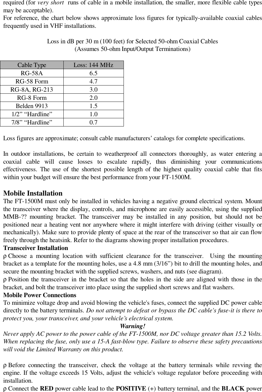
![2. Press the [MHz] key, then rotate the Main Dial knob to select the desired speed(50/250/450/750/1000 ms).3. Press and hold in the [MHz] key for one second to save the new setting and exit to the normaloperation.Interface of Packet TNCs & ResetThe FT-1500M provides a convenient rear-panel DATA jack for easy TNC interconnections, Refer tothe graphic and table for pin-out connections.Data rate selection (1200/9600 bps) can be selected via Menu “P RATE.”Normally, the microphone will be cut off during packet transmission, so as to avoid interference to thedata stream by voice input. However, this protection feature can be disabled, if you have some reasonto want the microphone to be active during packet transmission.To re-activate the microphone during packet transmission:1. Press and hold in the [MHz] key for one second, then rotate the Main Dial knob to select“PCKT.”2. Press the [MHz] key, then rotate the Main Dial knob to select “MIC ON.”3. Press and hold in the [MHz] key for one second to save the new setting and exit to normaloperation.To disable the microphone during packet transmission (the typical configuration), select “MIC OFF”in step 2 above.Packet operating procedures are governed by the software used by your computer and TNC. Consultthe documentation accompanying the software for details on packet operation.FM Bandwidth & Mic Gain ControlYou can reduce the microphone input level and transmitter bandwidth when operating on tightly-clustered frequencies (channel spacing of 12.5- or 15-kHz). This will reduce the transmitter deviation,thus minimizing interference to other users.To reduce the microphone input level:1. Press and hold in the [MHz] key for one second, then rotate the Main Dial knob to select “W/NDV.”2. Press the [MHz] key, then rotate the Main Dial knob to change the display to “NARROW.”3. Press and hold in the [MHz] key for one second to save the new setting and exit to normaloperation.To restore the normal (higher) microphone input level and normal (15 kHz) receiver bandwidth, select“WIDE” in step 2 above.Microprocessor ResettingTo perform a CPU master reset for all memories and Menu settings, press the [LOW], and [D/MR]keys while turning the transceiver on.Set Mode ResettingTo reset all Menu settings to their factory defaults, press the [REV] key and [D/MR] buttons whileturning the transceiver on.CloningYou can transfer all data stored in one transceiver to another set by utilizing the handy “Cloning”feature. This requires a user-constructed cloning cable which connects the MIC jacks on the twotransceivers as shown below.To clone from one transceiver to another, use the following procedure:1. Insert the Clone Cable into the MIC jack of each transceiver.2. Turn both transceivers off, then press and hold in the [LOW] key on each radio while turning thepower on again. The “CLN” notation will appear on the display.3. On the “destination” radio, press the [D/MR] button.4. Now, on the “source” radio, press the [MHz] key.](https://usermanual.wiki/Yaesu-Musen/FT-1500M/User-Guide-78533-Page-19.png)
![5. If there is a problem during the cloning process, “CLN ERR” will be displayed. Check your cableconnections and try again.6. If cloning is successful, turn the “destination” radio off. Now turn the “source” radio off.Remove the clone cable. Channel and operating data for both radios are now identical. They both maybe turned on now for normal operation.Set ModeThe FT-1500M’s Menu system allows a number of transceiver operating parameters to be custom-configured for your operating requirements.The Menu is easy to activate and set, using the following procedure:1. Press and hold in the [MHz] key for one second.2. Rotate the Main Dial knob to select the Menu item to be adjusted.3. Press the [MHz] key, then rotate the Main Dial knob to adjust the status or value of the Menuitem.4. After completing your adjustment, press and hold in the [MHz] key for one second to save thenew setting and exit to normal operation.Menu items are conveniently arranged in alphabetical order.Menu Selection SummarySet Mode DetailsSet Item [ALPH]Function: Programming an Alpha/Numeric label for a memory.See page ?? for details.Set Item [APO]Function: Enable/Disable the Automatic Power Off feature.Available Values: 1 ~ 12 Hours, or OFFDefault: OFFSet Item [ARS]Function: Enable/Disable the Automatic Repeater Shift function.Available Values: ON/OFFDefault: ONSet Item [BEEP]Function: Enable/Disable the key/button beeper.Available Values: ON/OFFDefault Setting: ONSet Item [BELL]Function: Enable/Disable the CTCSS Bell Paging feature.Available Values: ON/OFFDefault Setting: OFFSet Item [CH NUM]Function: Enable/Disable the momentary display of the Memory Channel Number as the Main Dialknob is rotated.Available Values: ON/OFFDefault Setting: OFFSet Item [CK SFT]Function: Shifting of CPU clock frequency..Available Values: ON/OFFDefault Setting: OFFSet Item [DC IN]Indicate the Supply VoltageSet Item [DIMR]Function: Setting of the front panel display’s illumination level.Available Values: 1 ~ 10 or OFF](https://usermanual.wiki/Yaesu-Musen/FT-1500M/User-Guide-78533-Page-20.png)
![Default Setting: 10Set Item [DTMF]Set Item [DT DLY]Function: Setting of the DTMF Autodialer Delay TimeAvailable Values: 50/250/450/750/1000 ms.Default Setting: 450 ms.Set Item [DT MEM]Function: Loading of the DTMF Autodialer Memories. See page ??.Set Item [DT SPD]Function: Setting of the DTMF Autodialer Sending SpeedAvailable Values: 50/100 ms.Default Setting: 50 ms (high speed)Set Item [EDG BP]Function: Enable/Disable the Band-edge beeper while scanning.Available Values: ON/OFFDefault Setting: OFFSet Item [LOCK]Function: Enable/Disable the key/button LockAvailable Values: KL/DL/K+D/PL/K+P/D+P/ALL/OFFDefault Setting: OFFSet Item [PCKT]Function: Enable/Disable the Microphone during Packet transmission.Available Values: Mic ON/Mic OFFDefault Setting: Mic OFFSet Item [P RATE]Function: Set the transceiver’s circuitry for the Packet baud rate to be used.Available Values: 1200/9600 bpsDefault Setting: 1200Set Item [PRG P1]Function: Programming the function assigned to microphone key P1Available Values: MON/S.SRCH/T.SRCH/WX/SQ.TYP/T.CALL/SHIFT/TX POWER/ANDefault Setting: MON (Squelch OFF)Set Item [PRG P2]Function: Programming the function assigned to microphone key P2Available Values: MON/S.SRCH/T.SRCH/WX/SQ.TYP/T.CALL/SHIFT/TX POWER/ANDefault Setting: S.SRCH (Smart Search)Set Item [PRG P3]Function: Programming the function assigned to microphone key P3Available Values: MON/S.SRCH/T.SRCH/WX/SQ.TYP/T.CALL/SHIFT/TX POWER/ANDefault Setting: T.SRCH (Tone Search)Set Item [PRG P4]Function: Programming the function assigned to microphone key P4Available Values: MON/S.SRCH/T.SRCH/WX/SQ.TYP/T.CALL/SHIFT/TX POWER/ANDefault Setting: WX (Weather Channel)Set Item [REV/HM]Function: Select the [REV] key function..Available Values: REV/HOMEDefault Setting: REVSet Item [RF SQL]Function: Adjust the RF Squelch threshold level.Available Values: OFF/S-1 to S-10](https://usermanual.wiki/Yaesu-Musen/FT-1500M/User-Guide-78533-Page-21.png)
![Default Setting: OFFSet Item [RPTER]Function: Enable/Disable the Automatic Repeater Shift feature and Setting of the Repeater ShiftDirectionAvailable Values: ARS/Shift -/Shift +/OFFDefault Setting: ARSSet Item [RVRT]Function: Enable/Disable the “Priority Channel Revert” featureAvailable Values: OFF/ONDefault Setting: OFFSet Item [SCAN]Function: Select the Scan Resume mode.Available Values: BUSY/5SEC/HOLDDefault Setting: BUSYSet Item [SHIFT]Function: Set the magnitude of the Repeater ShiftAvailable Values: 0.00 ~ 99.95 MHz (only shifts of less than 4 MHz will work)Default Setting: 600 kHzSet Item [SKIP]Function: Enable/Disable Skipping of a channel during scanning.Available Values: SKIP/STOPDefault Setting: STOP (Stop on busy channel)Set Item [SQL]Function: Set the Squelch thresholdAvailable Values: OFF/1 ~ 15 (arbitrary scale)Default Setting: 1Set Item [STEP]Function: Setting of the synthesizer steps used in VFO/Memory Tune operation.Available Values: 5/10/12.5/15/20/25/50 kHz per stepDefault Setting: 5 kHzSet Item [S.SRCH]Function: Select the Smart Search Sweep mode.Available Values: Single/ContinueDefault Setting: SingleSet Item [TONE]Function: Select the CTCSS mode.Available Values: OFF, T, TSQDefault Setting: OFFSet Item [TN FRQ]Function: Setting of the CTCSS Tone Frequency.Available Values: 39 standard CTCSS TonesDefault Setting: 100.0 HzSet Item [TOT]Function: Set the time-out limit for the Time-Out TimerAvailable Values: 1 ~ 60 minutes, or OFFDefault Setting: 6 minutesSet Item [W/N DV]Function: Reduction of the Microphone Gain/Deviation and receiver bandwidthAvailable Values: WIDE/NARROWDefault Setting: WIDE (±5 kHz Deviation, 15 kHz bandwidth)](https://usermanual.wiki/Yaesu-Musen/FT-1500M/User-Guide-78533-Page-22.png)