Yaesu Musen FT-857 Amateur Transceiver User Manual users manual
Yaesu Musen Co., Ltd. Amateur Transceiver users manual
UserManual.wiki
>
Yaesu Musen
>
FT 857 User Manual
users manual
Navigation menu
Upload a User Manual
Namespaces
Wiki Guide
HTML
PDF
Info
Views
User Manual
Discussion / Help
Navigation
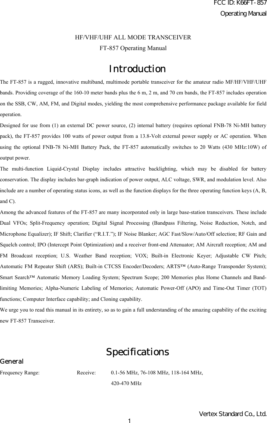
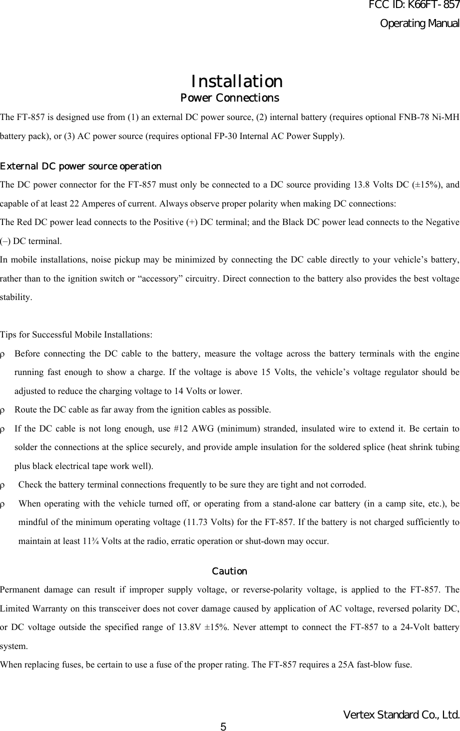
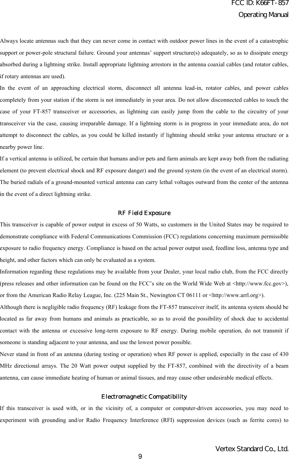
![FCC ID: K66FT-857Operating ManualVertex Standard Co., Ltd.10minimize interference to your communications caused by energy from the computer. Computer-generated RFI is usually aresult of inadequate shielding of the computer’s cabinet or I/O and peripheral connections. While computer equipmentmay “comply” with RF emission standards, this does not ensure that sensitive Amateur Radio receivers like the FT-857will not experience interference from the device!Be certain to use only shielded cables for TNC-to-Transceiver connections. You may need to install AC line filters on thepower cord(s) of the suspected equipment, and decoupling ferrite toroidal chokes may be required on interconnectingpatch/data cables. As a last resort, you can try installing additional shielding within the computer’s case, using appropriateconductive mesh or conductive shielding tape. Especially check “RF holes” where plastic is used for cabinet front panels.For further information, consult amateur radio reference guides and publications relating to RFI suppression techniques.Heat and VentilationTo ensure long life of the components, be certain to provide adequate ventilation around the cabinet of the FT-857. Thecooling system of the transceiver must be free to draw cool air in from the side of the transceiver and expel warm air fromthe rear of the transceiver.Do not install the transceiver on top of another heat-generating device (such as a linear amplifier), and do not placeequipment, books, or papers on top of the transceiver. Place the transceiver on a hard, flat, stable surface. Avoid heatingvents and window locations that could expose the transceiver to excessive direct sunlight, especially in hot climates.Heat Water & Moisture Dust VentilationLinear Amplifier InterfacingThe FT-857 provides the switching and drive-control lines required for easy interfacing to most all commonly-availableamplifiers sold today.These include:ρThe Antenna Jacks (“HF/50MHz” and “144/430MHz”);ρ A T/R control line (open circuit on RX, closure to ground on TX); andρ A negative-going ALC jack (control voltage range: 0V to –4V DC).ρWhen interfacing to the VL-1000 Solid State 1 KW Linear Amplifier, the optional CT-58 Interface Cable provides foreasy interconnection (requires that the Menu Mode No-020 [CAT/LIN/TUN] setting changes to “LINEAR”).The rear-panel ACC jack is a miniature stereo type, which accepts ALC control voltage input on the tip connection, andT/R control on the ring connection. The main shaft is used for the ground connection.Typical amplifier interface circuits are shown below.Note that some amplifiers, particularly VHF or UHF “brick” amplifiers, offer two methods of T/R switching: applicationof +13V or a closure to ground.](https://usermanual.wiki/Yaesu-Musen/FT-857/User-Guide-286869-Page-10.png)
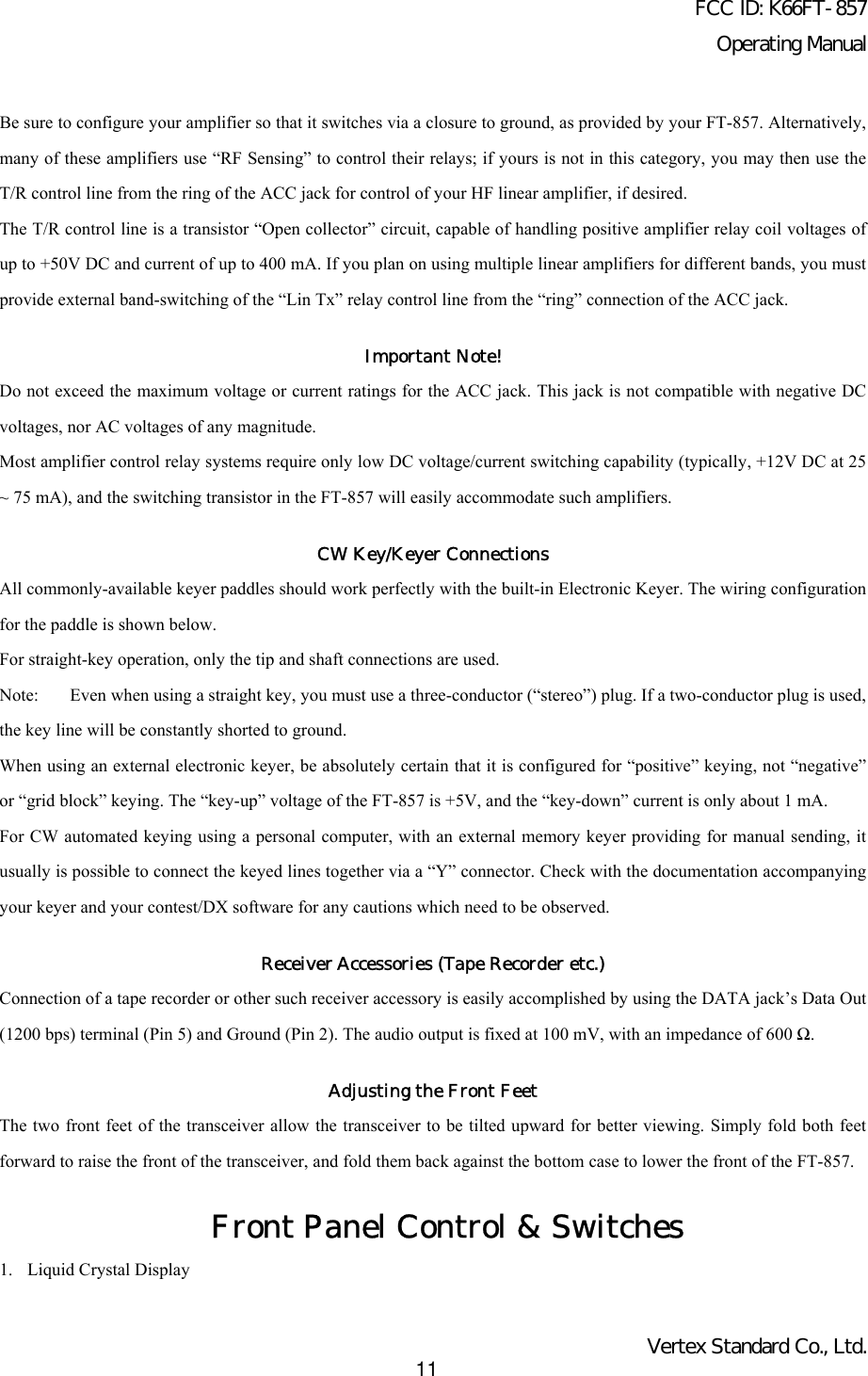
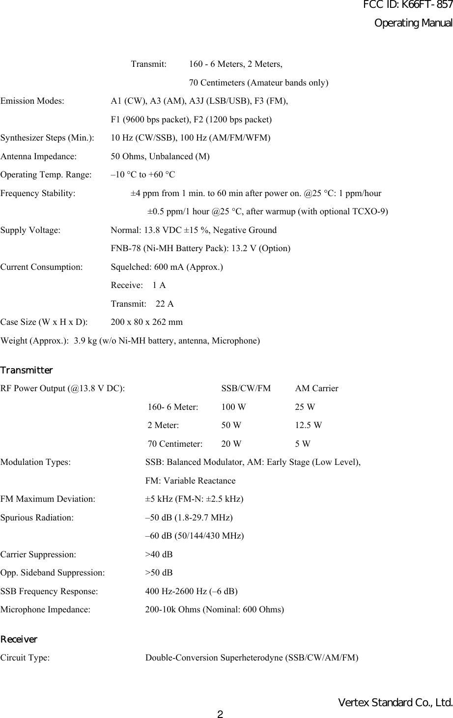
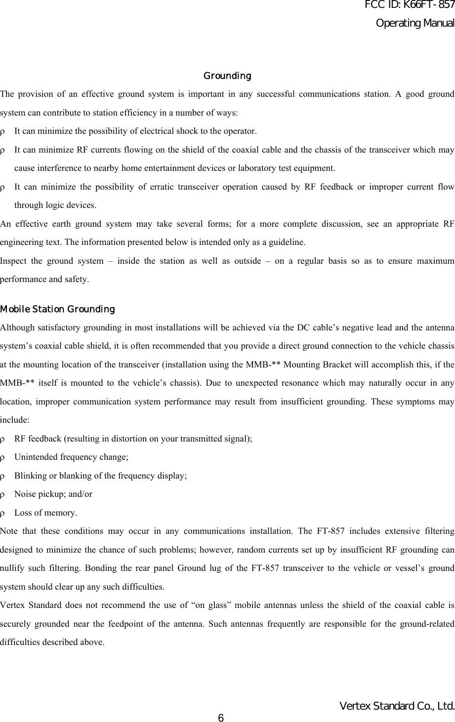
![FCC ID: K66FT-857Operating ManualVertex Standard Co., Ltd.12The Liquid Crystal Display (LCD) provides indication of the operating frequency and other aspects oftransceiver status.2. FUNC KeysThese three keys select many of the most important operating features of the transceiver. When you press the [F] key,then rotate the MEM/VFO CH knob, the current function of that key will appear above each of the [A], [B], and [C]keys (along the bottom of the LCD). You may scroll the display through 17 rows of functions available for use via the[A], [B], and [C] keys.The available features are shown in page 14.3. MIC JackConnect the supplied MH-31B8 Hand Microphone to this jack.4. PHONES JackThis 1/4-inch, 3-contact jack accepts either monaural or stereo headphones with 2- or 3-contact plugs. When a plug isinserted, the loudspeaker is disabled. The audio level varies according to the setting of the front panel’s AF knob.5. POWER SwitchPress and hold in the POWER switch for one second to turn to the transceiver on or off.6. [F] KeyPress this key momentarily to enable the changing of the function of the Multi Function keys ([A], [B],and [C]) by the MEM/VFO CH knob.Press and hold this key for one second to activate the “Menu” mode.7. LOCK KeyPressing this key locks the front panel keys so as to prevent accidental frequency change. The LOCK key itself,though, will never be disabled.8. MAIN DIALThis is the main tuning dial for the transceiver. It is used both for frequency tuning as well as “Menu” setting in thetransceiver.9. AF KnobThe (inner) VOL knob adjusts the receiver audio volume level presented to the internal or externalspeaker. Clockwise rotation increases the volume level.10. SQL/RF KnobIn the USA version, this (outer) SQL/RF knob adjusts the gain of the receiver’s RF and IF stages. Using MenuMode No-080 [SQL/RF GAIN], this control may be changed to function as a Squelch control, which may be used tosilence background noise when no signal is present. In the other versions, its default setting is set to “Squelch.”11. CLAR/IF SHIFT KeyPressing this key activates the Receiver Clarifier feature. When this feature is activated, the CLAR knob is used toset a tuning offset of up to ±9.99 kHz. The transmitter’s frequency is not affected by the setting of the Clarifier.Press and hold this key for one second to activate the IF Shift feature, which allows you to use the MEM/VFO CH](https://usermanual.wiki/Yaesu-Musen/FT-857/User-Guide-286869-Page-12.png)
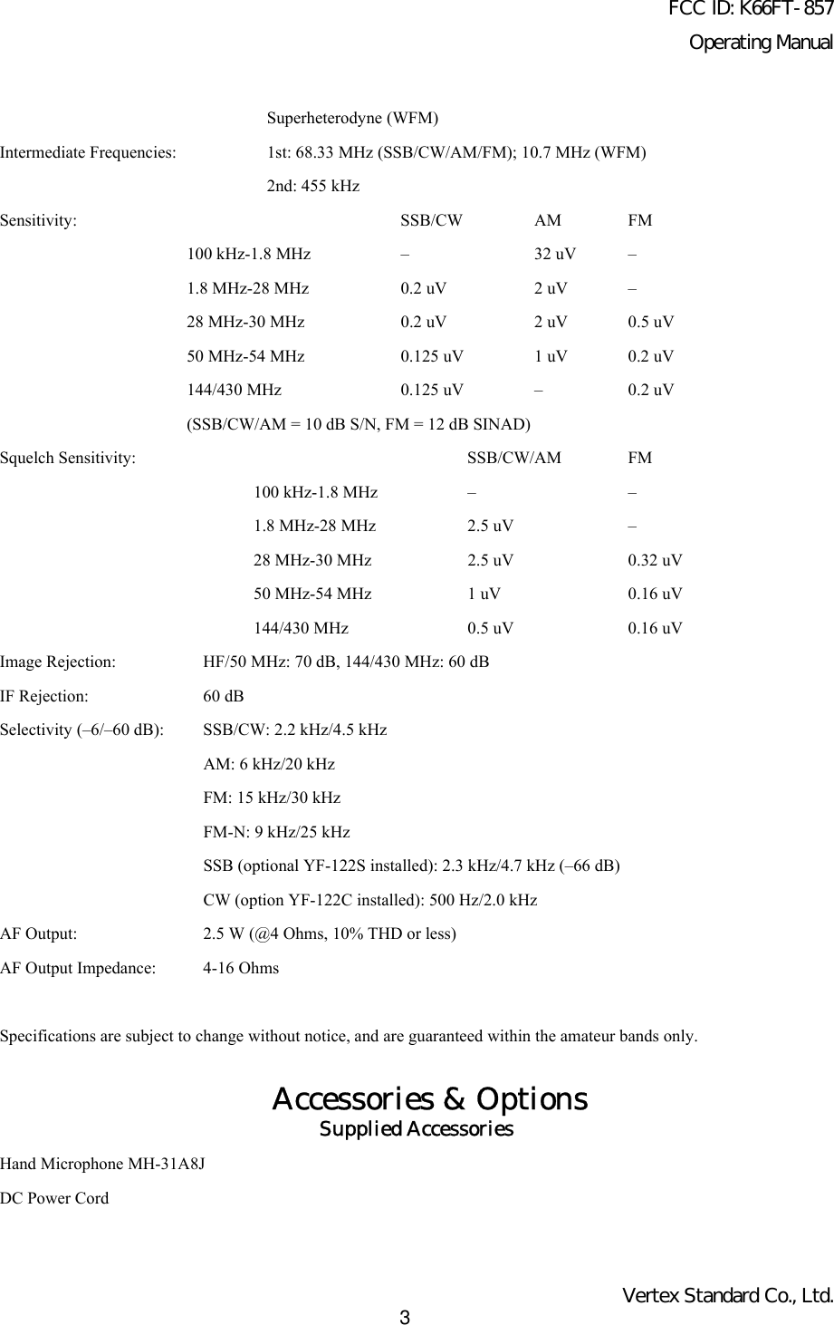
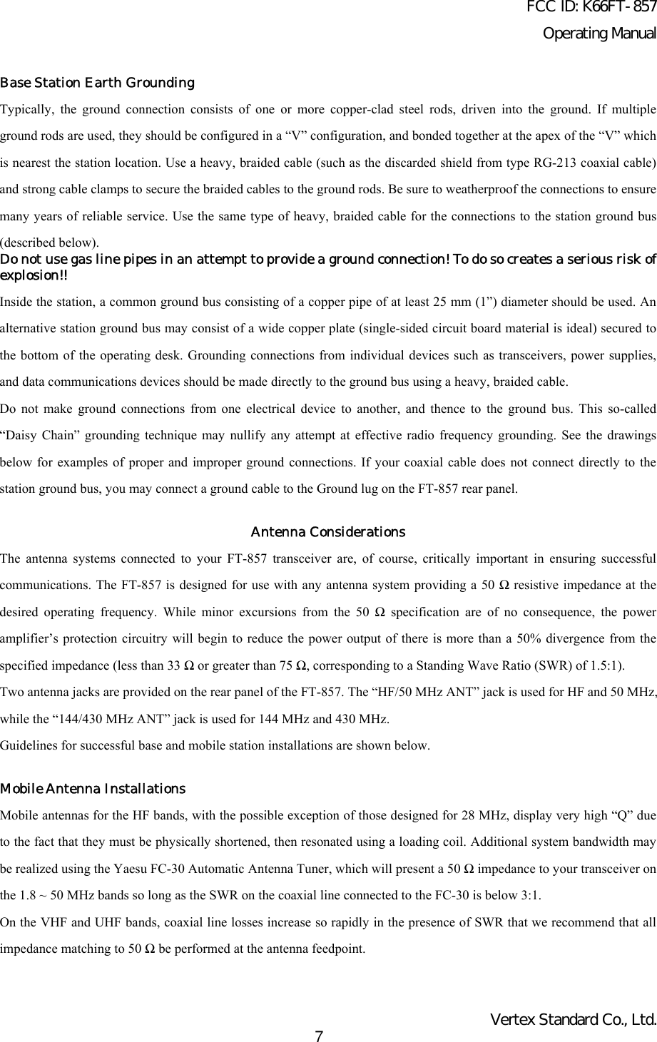
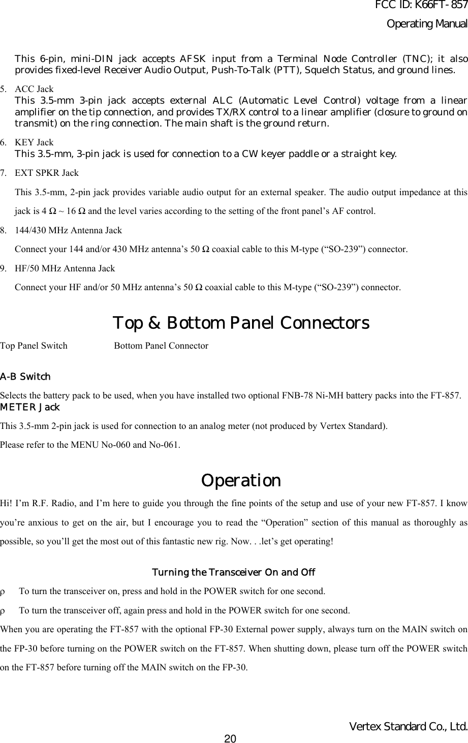
![FCC ID: K66FT-857Operating ManualVertex Standard Co., Ltd.13knob to adjust the center frequency of the IF filter’s passband response.12. CLAR KnobThis knob tunes the clarifier offset frequency up to ±9.99 kHz, when the Receiver Clarifier feature is activated bypressing the CLAR/IF SHIFT key.13. BAND(DWN)/BAND(UP) KeyPressing either of these keys momentarily will cause the frequency to be moved up or down by onefrequency band. The selections available are:.... 1.8 MHz √ 3.5 MHz √ 7.0 MHz √ 10 MHz √ 14 MHz √ 15 MHz √√ 18 MHz √ 24 MHz √ 28 MHz √ 50 MHz √ 88 MHz √ 108 MHz √√ 144 MHz √ 430 MHz √ 1.8 MHz ...14. MEM/VFO CH KnobThis detented rotary switch is used for VFO frequency tuning, memory selection, and functionselection for the [A], [B], [C] keys of the transceiver.15. DSP ButtonPressing this button momentarily provides instant access to Multi Function Row “p” (MFp), which contains thecommand key for the receiver’s Digital Signal Processing system. The available functions will appear as thefunctions displayed above the [A], [B], and [C] keys, as described previously.16. HOME KeyPressing this key momentarily recalls a favorite “Home” frequency memory.17. V/M KeyPressing this key switches frequency control between the VFO and Memory Systems.18. MODE(<)/MODE(>) KeyPressing either of these keys momentarily will change the operating mode. The selections availableare:... USB √ LSB √ CW √ CWR √ AM √ DIG √ PKT √ USB ...19. DSP IndicatorThis indicator glows green when the DSP feature is activated.20. TRANSMIT/BUSY IndicatorThis indicator glows green when the squelch opens, and turns red during transmit.21. CW-T IndicatorThis indicator is a visual tinning indicator for CW reception, which glows green in synchronizationwith a signal tuned to the center of the IF passband during CW reception.22. BATT-A, BATT-B IndicatorThese LEDs indicate the battery status for the optional FNB-78 Ni-MH battery pack while internalbattery operation.The LED glows green when the battery pack is waiting (switch to off by the A-B switch on the toppanel), and turns orange when the is the battery pack en the radio operate the corresponded batterypack by the A-B switch on the top panel.When the battery voltage is approaching the value which indicates depletion is near, the LED blinksorange, indicating it is time to replace the batteries.The [A], [B], and [C] keys select many of the most important operating features of the transceiver. When you press the [F]](https://usermanual.wiki/Yaesu-Musen/FT-857/User-Guide-286869-Page-13.png)
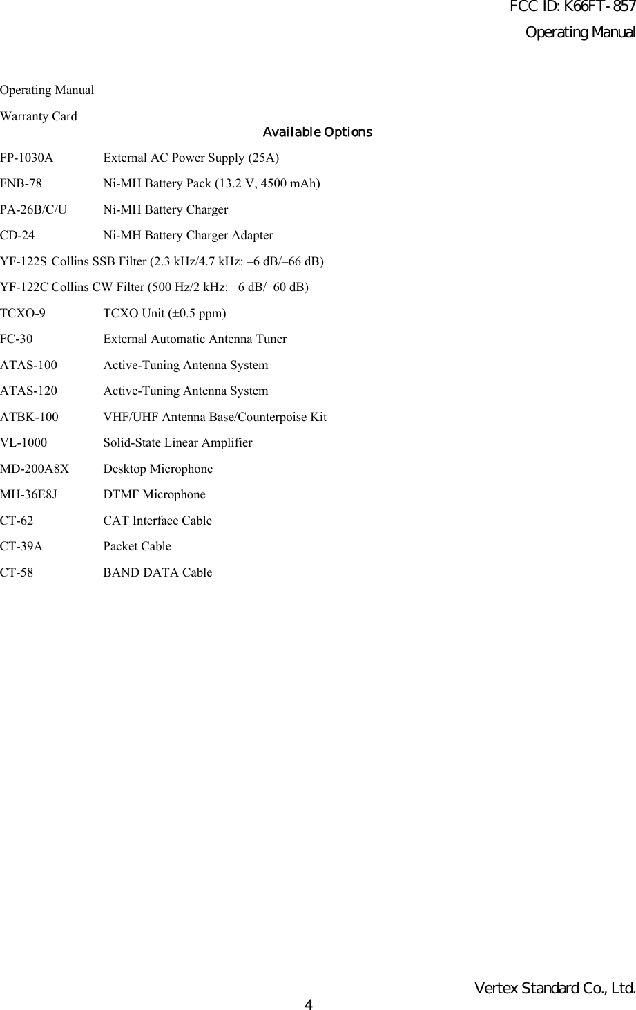
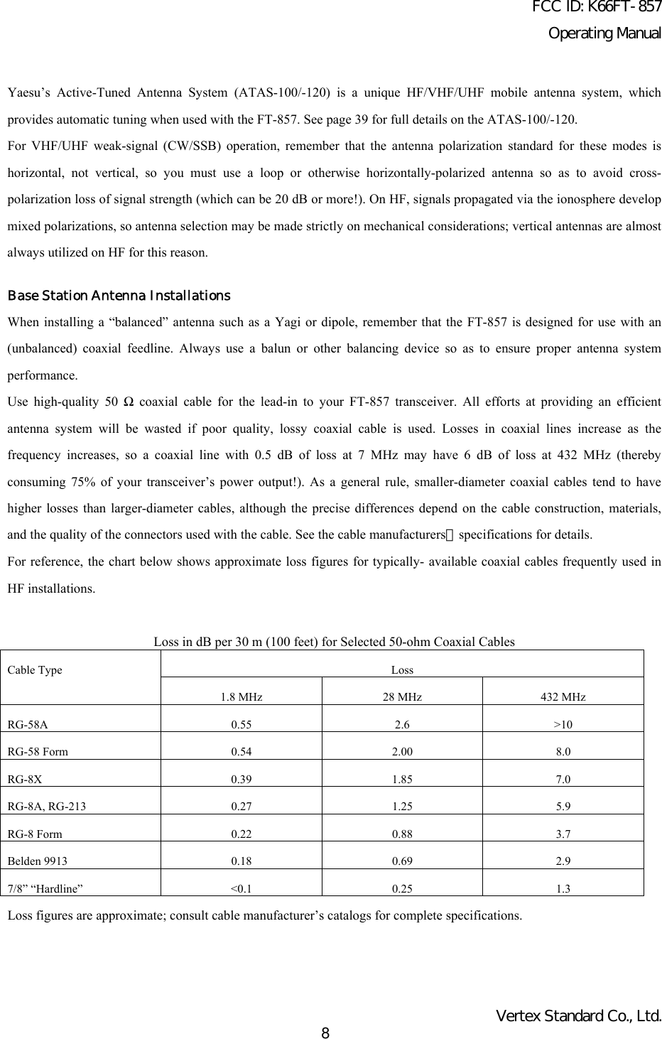
![FCC ID: K66FT-857Operating ManualVertex Standard Co., Ltd.14key, then rotate the MEM/VFO CH knob, the current function of that key will appear above each of the [A], [B], and [C]keys (along the bottom of the LCD). You may scroll the display through 17 rows of functions available for use via the [A],[B], and [C] keys.Multi Function Row “a” (MFa) [A/B, A=B, SPL][A] Key: A/BPress the [A](A/B) key to switch between VFO-A and VFO-B on the display.[B] Key: A=BPress the [B](A=B) key to copy the contents of Main VFO to be copied into the Sub VFO, so that the two VFO’s contentswill be identical.[C] Key: SPLPress the [C](SPL) key to activate Split frequency operation between VFO-A and VFO-B.Multi Function Row “b” (MFb) [MW, SKIP, TAG][A] Key: MWPress and hold in the [A](MW) key for one second to transfer the contents of the VFO into a Memory register.[B] Key: SKIPPress the [B](SKIP) key to designate the current Memory channel to be “skipped” during scanning.[C] Key: TAGPress the [C](TAG) key to select the display type (Frequency or Alpha-numeric Tag) during Memory operation.Multi Function Row “c” (MFc) [STO, RCL, PROC][A] Key: STOPress the [A](STO) key to store the contents of the VFO into the QMB (Quick Memory Bank) register.[B] Key: RCLPress the [B](RCL) key to recall the QMB Memory.[C] Key: PROCPress the [C](PROC) key to activate the speech processor for SSB and AM transmission.Press and hold in the [C](PROC) key for one second to recall Menu Mode No-074 [PROC LEVEL] (for setting thecompression level of the AF Speech Processor).Multi Function Row “d” (MFd) [RPT, REV, VOX][A] Key: RPTPress the [A](RPT) key to select the direction of the uplink frequency shift (+, – or simplex) during FM repeateroperation.](https://usermanual.wiki/Yaesu-Musen/FT-857/User-Guide-286869-Page-14.png)
 key for one second to recall Menu Mode No-076 [RPT SHIFT] (for setting the shiftfrequency offset).[B] Key: REVPress the [B](REV) key to reverse the transmit and receive frequencies while working through a repeater.[C] Key: VOXPress the [C](VOX) key enable the VOX (voice-operated transmitter switching system) in the SSB, AM, and FM modes.Press and hold in the [C](VOX) key for one second to recall Menu Mode No-088 [VOX GAIN] (for setting the VOX gainlevel).Multi Function Row “e” (MFe) [TON, -------, TDCH] ([ENC, DEC, TDCH])[A] Key: TON/ENCPress the [A](TON) key to activate CTCSS or DCS operation on FM.When the Split Tone feature is activated via Menu Mode No-079 [SPLIT TONE], this key function changes to “ENC” foractivation of the CTCSS Encoder or DCS Encoder. Press the [A](ENC) key to activate the encoder.Press and hold in the [A](TON/ENC) key for one second to recall Menu Mode No-083 [TONE FREQ] (for selecting theCTCSS tone frequency).[B] Key: ------/DECNormally, this key does nothing.When the Split Tone feature is activated via Menu Mode No-079 [SPLIT TONE], this key function changes to “DEC” toengage the DCS or CTCSS Decoder. Press the [B](DEC) key to activate the decoder.Press and hold in the [B](DEC) key for one second to recall Menu Mode No-033 [DCS CODE] (for selecting the DCScode).[C] Key: TDCHPress the [C](TDCH) key to initiate CTCSS Tone or DCS Search.Multi Function Row “f” (MFf) [ARTS, SRCH, PMS][A] Key: ARTSPress the [A](ARTS) key to initiate the Auto-Range Transponder mode.Press and hold in the [A](ARTS) key for one second to recall Menu Mode No-008 [ARTS BEEP] (for selecting the ARTS“Beep” option).[B] Key: SRCHPress the [B](SRCH) key to activate the Smart Search feature.Press the [B](SRCH) key to initiate Smart Search scanning.[C] Key: PMS](https://usermanual.wiki/Yaesu-Musen/FT-857/User-Guide-286869-Page-15.png)
 key to activate the Programmable Memory Scan feature.Multi Function Row “g” (MFg) [SCN, PRI, DW][A] Key: SCNPress the [A](SCN) key to initiate the Scanning (in the direction of higher frequencies).[B] Key: PRIPress the [B](PRI) key to activate the Priority Scan feature.[C] Key: DWPress the [C](DW) key to activate the Dual Watch feature.Multi Function Row “h” (MFh) [SCOP, WID, STEP][A] Key: SCOPPress the [A](SCOP) key to activate the Spectrum Scope Monitor feature.Press and hold in the [A](SCOP) key for one second to initiate the Spectrum Scope.[B] Key: WIDPress the [B](WID) key to select the visible bandwidth for the Spectrum Scope Monitor.Press and hold in the [B](WID) key for one second to select the operating mode for the Spectrum Scope Monitor.[C] Key: STEPPress the [C](STEP) key to select the channel steps for Spectrum Scope Monitor.Press and hold in the [C](STEP) key for one second to activate the MAX HOLD feature, which will display and hold thepeak signal strength level for each channel.Multi Function Row “i” (MFi) [MTR, --------, DISP][A] Key: MTRPressing the [A](MTR) key repeatedly allows selection of the display function of the meter in the transmit mode.PWR ∏ ALC ∏ SWR ∏ MOD ∏ PWR ∏The selected function will appear above the [B] key.Press and hold in the [A](MTR) key for one second to recall Menu Mode No-062 [MTR PEAK HOLD] (for setting the“peak-Hold” function of the meter).[B] KeyPressing the [B] key repeatedly allows selection of the display function of the meter in the transmit mode.PWR ∏ MOD ∏ SWR ∏ ALC ∏ PWR ∏[C] Key: DISPPress the [C](DISP) key to switch the display between the Large Character and Small Character modes.](https://usermanual.wiki/Yaesu-Musen/FT-857/User-Guide-286869-Page-16.png)
![FCC ID: K66FT-857Operating ManualVertex Standard Co., Ltd.17Multi Function Row “j” (MFj) [SPOT, BK, KYR][A] Key: SPOTPress the [A](SPOT) key to activate the CW spotting heterodyne oscillator.[B] Key: BKPress the [B](BK) key to disable the CW “Semi” break-in operation.Press and hold in the [B](BK) key for one second to recall Menu Mode No-029 [CW SIDE TONE] (for setting the CWside tone volume level).[C] Key: KYRPress the [C](KYR) key to activate the built-in Electronic Keyer.Press and hold in the [C](KYR) key for one second to recall Menu Mode No-030 [CW SPEED] (for setting the Keyerspeed).Multi Function Row “k” (MFk) [TUNE, DOWN, UP][A] Key: TUNEPress the [A](TUNE) key to activate the optional FC-30 Automatic Antenna Tuner or ATAS-100/-120 Active-TuningAntenna System.Press and hold in the [A](TUNE) key for one second to initiate tuner or antenna retuning.[B] Key: DOWNPress and hold in the [B](DOWN) key to lower the ATAS-100/-120 antenna manually.[C] Key: UPPress and hold in the [C](UP) key to raise the ATAS-100/-120 antenna manually.Multi Function Row “l” (MFl) [NB, AGC, --------][A] Key: NBPress the [A](NB) key to activate the receiver’s IF Noise Blanker.Press and hold in the [A](NB) key for one second to recall Menu Mode No-063 [NB LEVEL] (for setting of the NBlevel).[B] Key: AGCPress the [B](AGC) key to disable the receiver’s AGC system. Normally, the AGC should be left On.[C] KeyPress the [C] key to select the recovery time (Slow, Fast, or Auto) for the receiver’s AGC system.Multi Function Row “m” (MFm) [IPO, ATT, NAR][A] Key: IPO](https://usermanual.wiki/Yaesu-Musen/FT-857/User-Guide-286869-Page-17.png)
 key to bypass the receiver preamplifier, thereby activating Intercept Point Optimization for improvedoverload characteristics while operating on the HF and 50 MHz bands.The IPO feature does not function on 144/430 MHz.[B] Key: ATTPress the [B](ATT) key to engage the receiver front-end attenuator, which will reduce all signals and noise byapproximately 10 dB.The ATT feature does not function on 144/430 MHz.[C] Key: NARPress the [C](NAR) key to select the low-deviation mode required for HF FM operation on 29 MHz.Multi Function Row “n” (MFn) [CFIL,--------,--------][A] Key: CFILPress the [A](CFIL) key to select the 2.4 kHz ceramic IF filter.[B] KeyPress the [B] key to select the optional IF filter which is located on the “FIL-1” (Optional Filter 1) slot on the Main Unit.When an optional filter is not installed on the “FIL-1” slot, this key function is disabled, and its label is “N/A.”[C] KeyPress the [C] key to select the optional IF filter which is located on the “FIL-2” (Optional Filter 2) slot on the Main Unit.When an optional filter is not installed on the “FIL-2” slot, this key function is disabled, and its label is “N/A.”Multi Function Row “o” (MFo) [PLY1, PLY2, PLY3][A] Key: PLY1Press the [A](PLY1) key to send the CW message which is memorized in BEACON TEXT 1.[B] Key: PLY2Press the [B](PLY2) key to send the CW message which is memorized in Keyer BEACON TEXT 2.[C] Key: PLY3Press the [C](PLY3) key to send the CW message which is memorized in Keyer BEACON TEXT 3.Multi Function Row “p” (MFp) [DNR, DNF, DBF][A] Key: DNRPress the [A](DNR) key to activate the DSP Noise Reduction system.Press and hold in the [A](DNR) key for one second recall Menu Mode No-049 [DSP NR LEVEL] (for setting the degreeof DSP Noise Reduction).[B] Key: DNF](https://usermanual.wiki/Yaesu-Musen/FT-857/User-Guide-286869-Page-18.png)
 key to activate the DSP’s Auto Notch Filter.[C] Key: DBFPress the [C](DBF) key to activate the DSP’s receiver Bandpass Filter.In the SSB, AM, FM, and AFSK modes, press and hold in the [C](DBF) key for one second to recall Menu Mode No-047[DSP LPF CUTOFF] (for adjusting the high-frequency cutoff of the DSP Bandpass Filter).In the CW mode, press and hold in the [C](DBF) key for one second to recall Menu Item No-045 [DSP BPF WIDTH] (forsetting the CW bandwidth).Multi Function Row “q” (MFq) [MONI, QSPL, ATC][A] Key: MONIPress the [A](MONI) key to disable the Noise Squelch.You may program the configuration of this key by the Menu Mode No-065 [PG A].[B] Key: QSPLPress the [B](QSPL) key to change the Sub VFO frequency (Main VFO frequency + 5 kHz) and automatically engage the“split” feature.You may program the configuration of this key by the Menu Mode No-066 [PG B].[C] Key: ATCPress the [C](ATC) key to activate a 1750-Hz burst tone for 2 seconds when pressing the PTT switch while the channel isclear.You may program the configuration of this key by the Menu Mode No-067 [PG C].Rear Panel Connectors1. INPUT JackThis is the DC power supply connection for the transceiver, used when operating the transceiver withan external power supply. Use the supplied DC cable to connect this jack to the car battery or DCpower supply, which must be capable of supplying at least 22A @ 13.8 VDC. For base station operation,the optional FP-30 External AC power supply may be attached to the bottom of the transceiver andconnect the output pigtail of the FP-30 to this jack.2. GND TerminalFor best performance and safety, this Ground lug may be connected to a good earth ground using ashort, heavy, braided cable.3. CAT/LINEAR JackThis 8-pin mini-DIN jack is used for connection to the FC-30 External Automatic Antenna Tuner orATAS-100/-120 Active-Tuning Antenna System. It is also used for interfacing to a personal computerfor control of the transceiver using the CAT system, and for interconnection to the VL-1000 LinearAmplifier.4. DATA Jack](https://usermanual.wiki/Yaesu-Musen/FT-857/User-Guide-286869-Page-19.png)
![FCC ID: K66FT-857Operating ManualVertex Standard Co., Ltd.21Operating Band SelectionThis transceiver covers an incredibly wide frequency range, over which a number of different operating modes are used.Therefore, this transceiver’s frequency coverage has been divided into different operating bands, each of with has its ownpre-set frequency steps and operating modes. You can change the channel steps and operating mode once you get started,of course, per the next section.To change the frequency band, press either the BAND(DWN) or BAND(UP) key to move to the next lower or higheroperating band, respectively.VFOa and VFOb are independent VFOs, so they may be set to different bands. See the “Stacked VFO System” discussionon page 22 for details.Menu Quick StartMany aspects of this transceiver’s configuration may be customized using the convenient “Menu” system, which allowyou to configure many “set and forget” settings just the way you want to. A full discussion of the Menu system begins onpage 52; for now, here is a brief discussion on how to change Menu settings:1. Press and hold in the [F] key for one second to enter the Menu mode.2. Rotate the MEM/VFO CH knob to recall the Menu Item to be changed (for example, Menu Mode No-001 [EXTMENU], which Enables or Disables the “Extended Menu” Mode).3. Rotate the DIAL knob to set this feature (in this example, the default setting is “OFF (Disabled),” so rotate the DIALknob to set this feature to “ON” (Enabled).4. Press and hold in the [F] key for one second to save the new setting and exit to normal operation.If you have momentarily pressed the [F] key to enable the changing of the function of the Multi Function keys ([A], [B],and [C]) by the MEM/VFO CH knob.Mode SelectionPress either the MODE(<) or MODE(>) key to move among the eight settings for the operating modes, respectively.where “CWR” is “CW-Reverse,” using the opposite sideband from the “default” BFO injection sideband (in most cases,the default injection sideband is on the “USB” side); “DIG” is an AFSK-based Digital mode, set up per Menu Mode No-038 [DIG MODE]; and “PKT” represents either 1200 or 9600 bps FM packet.You can set VFOa and VFOb to different modes in the same band, allowing you to have a “Phone” VFO and a “CW”VFO, for example.Adjusting the Audio Volume LevelRotate the AF knob to set a comfortable listening level.](https://usermanual.wiki/Yaesu-Musen/FT-857/User-Guide-286869-Page-21.png)
![FCC ID: K66FT-857Operating ManualVertex Standard Co., Ltd.22When operating in the “DIG” or “PKT” modes, you may set the AF knob to any comfortable setting, or even all the wayoff, because the output from the DATA jack is a fixed-level audio signal.Start with the AF knob set fully counter-clockwise, especially when using FM (the background noise on FM can besurprisingly loud)!Adjusting the RF Gain and SquelchThe SQL/RF Gain control is configured differently, depending on the country to which the FT-857 has been exported. Inthe U.S. version, the default function of this control is “RF Gain.” The configuration of the SQL/RF Gain control is set viaMenu Mode No-080 [SQL/RF GAIN]; see page 59 for details.If your transceiver is configured for “RF Gain” use, rotating this control fully clockwise in the SSB/CW/Digital modeswill provide best sensitivity. To reduce the receiver’s RF Gain somewhat, rotate this control counter-clockwise slightly.You will observe an increasing number of bars on the S-meter as you rotate the RF Gain control counter-clockwise; thisindicates increasing AGC voltage, which is causing the front-end gain to be reduced. In the FM and Packet modes, thiscontrol will automatically be set to “Squelch,” even though the setting of Menu Mode No-080 [SQL/RF GAIN] is “RFGain.” If this control is configured for “SQL” operation, the FT-857’s RF Gain will be set for maximum sensitivity in allmodes, and the SQL/RF Gain control will function solely as a Squelch control. In this case, rotate the SQL/RF Gaincontrol to the point where the background noise is just silenced; this will provide the best sensitivity to weak signals,while keeping the receiver quiet when no signal is received. The LED just above the Main Dial will glow Green when thesquelch is opened by an incoming signal or noise.Battery consumption is significantly reduced if the receiver is squelched, as the audio amplifier stage is shut off when thereceiver is muted.Setting the Operating Frequency1. In the “SSB/CW/DIG” modes, rotate the DIAL knob to set the frequency. Clockwise rotation of the DIAL increasesthe operating frequency.2. In the “AM/FM/PKT” modes, rotate the MEM/VFO CH knob to set the frequency. Clockwise rotation of theMEM/VFO CH increases the operating frequency.3. You may also use the MEM/VFO CH knob to adjust the operating frequency in the “SSB/CW/DIG” modes. TheMEM/VFO CH knob provides faster tuning, ideal for making quick changes in frequency when you want to moveacross the band in a hurry. You can then use the DIAL knob to make fine frequency adjustments.The synthesizer steps for the MEM/VFO CH knob may be adjusted independently by mode. Use Menu Mode No-006](https://usermanual.wiki/Yaesu-Musen/FT-857/User-Guide-286869-Page-22.png)
![FCC ID: K66FT-857Operating ManualVertex Standard Co., Ltd.23[AM STEP] for AM, No-052 [FM STEP] for FM, and No-082 [SSB STEP] for SSB/CW/Digital. See pages 54, 57, and 59for details.If you press the MEM/VFO CH knob momentarily, then rotate the MEM/VFO CH knob, you can now change theoperating frequency in 1 MHz steps, allowing very quick frequency excursions. This can be particularly helpful on theVHF and UHF bands.In step 2 above, it was mentioned that tuning in the “AM/FM/PKT” modes is accomplished using the MEM/VFO CHknob. By default, the DIAL is disabled in these modes; if you wish to enable the DIAL in these modes, use Menu ModeNo-004 [AM&FM DIAL]; see page 54.The main DIAL synthesizer’s tuning rate (the number of steps per rotation of the DIAL) can be adjusted using MenuMode No-035 [DIAL STEP]. See page 56 for details.Stacked VFO SystemPress the [F] key momentarily, then rotate the MEM/VFO CH knob, as needed, until Multi Function Row “a” [A/B, A=B,SPL] appears on the display.Now press the [A](A/B) key to toggle between the “A” and “B” VFOs. There are two such VFOs provided on eachAmateur band, so you may set VFO-A to the CW sub-band, and VFO-B to the SSB sub-band, if you like. The operatingmode will be preserved, along with the frequency information, on each VFO.When changing bands on either the “A” or “B” VFO, the two VFOs do not change bands together. This facilitates split-band operation, such as on FM satellites.Receiver AccessoriesLocking Front Panel ControlsThe front panel LOCK button allows you to disable the DIAL and/or the front panel controls.In the transceiver’s default configuration, pressing the LOCK button disables just the DIAL, while the other keys andswitches are unaffected.To lock out the remainder of the controls and the MEM/VFO CH knob, use Menu Mode No-054 [LOCK MODE];1. Press and hold in the [F] key for one second to enter the Menu mode.2. Rotate the MEM/VFO CH knob so as to recall No-054 [LOCK MODE].3. Rotate the DIAL to select the desired configuration:DIAL: Locks DIAL knob only.FREQ: Locks front panel keys and knobs related to frequency control (such as BAND(DWN) and BAND(UP)key, [A](A/B) key., etc.)PANEL: Locks all front panel keys and knobs (except POWER and LOCK keys)](https://usermanual.wiki/Yaesu-Musen/FT-857/User-Guide-286869-Page-23.png)
![FCC ID: K66FT-857Operating ManualVertex Standard Co., Ltd.24ALL: Locks all front panel keys and knobs (except POWER and LOCK keys) and microphone keys.4. When you have made your selection, Press and hold in the [F] key for one second to save the newsetting and exit to normal operation.When the controls are locked out, press the LOCK button once more to release them to normal operation.IF SHIFTThe receiver’s IF SHIFT feature is an effective interference-reduction tool, which allows you to shift the passbandresponse higher or lower without changing the pitch of the incoming signal.1. Press and hold in the CLAR/IF SHIFT button for one second to activate the IF SHIFT feature. An icon, such as “”,“S” (slightly shifted to the upper side), “SS” (more shifted to the upper side), “T”(slightly shifted to the lowerside),” or “TT” (more shifted to the lower side)” icon will appear at the right of the frequency display to indicate theIF SHIFT’s current position.2. Rotate the CLAR knob, as needed, to reduce or eliminate the interference.3. To turn the IF SHIFT feature off, again press and hold in the CLAR/IF SHIFT button for one second. The last settingof the IF SHIFT control will be retained until you change it again.If you wish to make a more permanent shift in the receiver’s IF passband, use Menu Mode No-015 [CAR LSB R] (forLSB mode) or No-017 [CAR USB R] (for USB mode). This allows you to set up a higher or lower listening pitch, if youprefer such as compared to the default passband response. See page 55.AGC (Automatic Gain Control)The receiver recovery time constant of the AGC system may be modified to match your operating needs.1. Press the [F] key momentarily, then rotate the MEM/VFO CH knob, as needed, until Multi Function Row “l” [NB,AGC, AUTO] appears on the display.2. Press the [C] key to toggle the AGC recovery time constant among the following selections:AUTO ∏ FAST ∏ SLOW ∏ AUTO ∏where “AUTO” represents “FAST” on CW and DIG (AFSK), and “SLOW” on the voice modes.If you disable the AGC by pressing the [B](AGC) key (to make the parentheses disappear), the S-meter (which monitorsAGC voltage) will cease to function. Depending on the setting of the RF Gain control, incoming signals will probably bedistorted if the AGC is turned off.Noise BlankerThe IF Noise Blanker may be useful in reducing or eliminating some types of impulse noise, especially noise generated](https://usermanual.wiki/Yaesu-Musen/FT-857/User-Guide-286869-Page-24.png)
![FCC ID: K66FT-857Operating ManualVertex Standard Co., Ltd.25by automotive ignition systems.1. Press the [F] key momentarily, then rotate the MEM/VFO CH knob, as needed, until Multi Function Row “l” [NB,AGC, OFF] appears on the display.2. Press the [A](NB) key to activate the Noise Blanker. Parentheses will appear on both sides of the “NB” selection,indicating that the Noise Blanker is now on.3. To adjust the blanking level, press and hold in the [A](NB) key for one second. This instantly activates Menu ModeNo-063 [NB LEVEL], which allows adjustment of Noise Blanking Level. Rotate the DIAL knob to set a higher orlower blanking level (on a scale of 0 to 100). When done, press and hold in the [F] key for one second to save the newsetting and return to normal operation.4. Press the [A](NB) key again to turn the Noise Blanker off.IPO (Intercept Point Optimization)The IPO feature bypasses the receiver RF preamplifier, thereby eliminating the preamp’s gain. This feature is notavailable on the 144 MHz and 430 MHz bands.1. Press the [F] key momentarily, then rotate the MEM/VFO CH knob, as needed, until Multi Function Row “m” [IPO,ATT, NAR] appears on the display.2. Press the [A](IPO) key to bypass the receiver input preamplifier. Parentheses will appear on both sides of the “IPO”selection, and the “IPO” icon will appear on the display. indicating that the preamp is now disengaged from thereceiver circuit.3. Press the [A](IPO) key once more to re-activate the preamp.On the bands below 14 MHz, the input preamplifier is rarely necessary, and activation of the IPO feature will providesubstantial protection against intermodulation and other problems associated with strong signal input to the receiver. Ruleof thumb: so long as the S-meter is moving on background noise, additional front-end gain is not necessary.ATT (Front End Attenuator)The Attenuator will reduce all signals (and noise) by 10 dB, and it may be used to make reception more pleasant underextremely noisy conditions. This feature is not available on the 144 MHz and 430 MHz bands.1. Press the [F] key momentarily, then rotate the MEM/VFO CH knob, as needed, until Multi Function Row “m” [IPO,ATT, NAR] appears on the display.2. Press the [B](ATT) key to activate the Attenuator. Parentheses will appear on both sides of the “ATT” selection, andthe “ATT” icon will appear on the display.3. Press the [B](ATT) key once more to switch the Attenuator out of the receiver front end circuit. Signals will again bereceived at a level 10 dB louder than was the case when the Attenuator was engaged.](https://usermanual.wiki/Yaesu-Musen/FT-857/User-Guide-286869-Page-25.png)
![FCC ID: K66FT-857Operating ManualVertex Standard Co., Ltd.26DSP Bandpass FilterIn the SSB mode, the receiver’s selectivity may be enhanced via the DSP Bandpass Filter.1. Press the [DSP] key momentarily. This instantly activates Multi Function Row “p” [DNR, DNF, DBF].2. Press the [C](DBF) key to activate the DSP Bandpass Filter. Parentheses will appear on both sides of the “DBF”selection, and the “DSP” will appear at the center top on the display. You will notice a decrease in both backgroundnoise and interference, if any is present.3. The bandwidth of the DSP filter may be modified, to customize the bandwidth to your operating needs. To adjust theLow-Cut and High-Cut characteristics of the DSP Bandpass Filter:・Press and hold in the [C](DBF) key for one second. This instantly activates Menu Mode No-047 [DSP LPFCUTOFF], which allows adjustment of the High-Cut (Low-Pass) filter.・Turn the DIAL, as desired, to adjust the high-frequency cutoff of the DSP Bandpass Filter.・Now rotate the MEM/VFO CH knob one click counter-clockwise to select Menu Mode No-047 [DSP HPFCUTOFF], which allows adjustment of the Low-Cut (High-Pass) filter.・Turn the DIAL, as desired, to adjust the low-frequency cutoff of the DSP Bandpass Filter.・When done, press and hold the [F] key for one second to save the new setting(s) and return to normal operation.4. Press the [C](DBF) key once more to disable the DSP Bandpass Filter.DSP CW Peaking FilterIn the CW mode, pressing the [C](DBF) key in Multi Function Row “p” [DNR, DNF, DBF] activates a narrow-bandwidthpeaking filter, which may be ideal for use under very crowded conditions. The DSP CW Peaking Filter also is especiallyhelpful under VHF/UHF weak-signal situations.The center frequency of the DSP CW Peaking Filter is automatically aligned to be centered on the response you haveselected via the Menu Mode in item No-027 [CW PITCH]. See page 55 for details.To change the bandwidth of the DSP CW Peaking Filter:1. Press and hold in the [C](DBF) key for one second on the CW mode. This instantly activates MenuMode No-045 [DSP BPF WIDTH], which allows selection of the bandwidth of the DSP CW PeakingFilter.2. Rotate the DIAL to select the desired bandwidth. The available values are 60 Hz, 120 Hz, and 240 Hz (default value:240 Hz).3. When you have made your selection, press and hold in the [F] key for one second to save the new setting and return tonormal operation.DSP Noise Reduction (NR)The Noise Reduction feature of the DSP system may be used to enhance signal-to-noise ratio on weak signals.1. Press the [DSP] key momentarily. This instantly activates Multi Function Row “p” [DNR, DNF, DBF].](https://usermanual.wiki/Yaesu-Musen/FT-857/User-Guide-286869-Page-26.png)
 key to activate the DSP Noise Reduction feature. “Parentheses” will appear on the both sides ofthe “DNR” indication, and the “DSP” will appear at the center top on the display.3. Now press and hold in the [A](DNR) key for one second. This instantly activates Menu Mode No-049 [DSP NRLEVEL], which allows adjustment of the DSP Noise Reduction level.4. Rotate the DIAL to find the point where best signal-to-noise ratio is obtained under the current noise conditions.5. Press and hold in the [F] key for one second to save the new setting and exit to normal operation.6. To turn off the DSP Noise Reduction feature, press the [A](DNR) key again.If noise is present at a level which causes indication on the S-meter, the performance of the Noise Reduction filter may beenhanced by rotating the SQL/RF (RF Gain) control in a counter-clockwise direction so as to set the (fixed) S-meterreading at the same level as the noise peaks. This adjustment raises the AGC threshold of the receiver.DSP Notch FilterThe DSP system’s Notch Filter may be helpful in removing one or more offending carrier or heterodyne signals from theaudio passband.1. Press the [DSP] key momentarily. This instantly activates Multi Function Row “p” [DNR, DNF, DBF].2. Press the [B](DNF) key to activate the Notch Filter. “Parentheses” will appear on the both sides of the “DNF”indication, and the “DSP” will appear at the center top on the display. You will notice that the audio level of thecarrier signal is now being reduced.3. Press the [B](DNF) key once more to turn the Notch Filter off.Do not activate this filter in the CW mode, as incoming CW signals will be notched out of the audio passband!AM/FM Tuning Dial OperationIn the AM and FM modes, the DIAL knob is locked out (via the setting of Menu Mode No-004 [AM&FM DIAL]) so as toallow “channelized” tuning on these modes. To adjust the operating frequency, simply rotate the MEM/VFO CH knob.If you wish to enable the DIAL for tuning in the AM and FM modes, change the setting of Menu Mode No-004 [AM&FMDIAL]. See page 54 for details.The “channelized” mode of tuning on AM and FM automatically rounds off the frequency to the next “logical” step whenyou rotate the MEM/VFO CH knob one “click” in either direction. This eliminates the inconvenience of having to presetthe frequency to an “even” channel.](https://usermanual.wiki/Yaesu-Musen/FT-857/User-Guide-286869-Page-27.png)
![FCC ID: K66FT-857Operating ManualVertex Standard Co., Ltd.28Automatic Power-Off FeatureThe APO feature helps conserve battery life by automatically turning the transceiver off after a user-defined period oftime within which there has been no dial or key activity. The available selections for the time before power-off are 1 ~ 6hours, as well as “APO Off.” The default condition for the APO is OFF, and here is the procedure for activating it:1. Press and hold the [F] key for one second to enter the Menu mode.2. Rotate the MEM/VFO CH knob to recall Menu Mode No-007 [APO TIME].3. Rotate the DIAL knob to select the desired time period after which the radio will automatically shut down.4. Press and hold in the [F] key for one second to save the new setting and exit to normal operation.Once you have programmed a time interval, the APO countdown timer will start whenever some front panel action(tuning, transmission, etc.) is completed.When the APO is activated, the “APO” icon will appear at the center top on the LCD. If there is no action by you withinthe time interval programmed, the microprocessor will shut down the radio automatically.Just press and hold in the POWER switch for one second to turn the transceiver back on after an APO shutdown, as usual.The APO feature will be disabled while using the Beacon or ARTS features, even if the APO feature is set to “ON.”Transmitter OperationSSB/AM TransmissionBasic Setup/Operation1. Press the MODE(<) or MODE(>) key so as to select either SSB (LSB/USB) or the AM mode. In the SSB mode, ifyou are operating on the 7 MHz or lower bands, select the LSB mode. If you are operating on the 14 MHz or higherbands, select the USB mode.2. Press the [F] key momentarily, then rotate the MEM/VFO CH knob, as needed, until Multi Function Row “i” [MTR,PWR, DISP] appears on the display.3. Now press the [A](MTR) or [B] key to select the “ALC” meter function (“ALC” will appear above the [B] key). Youmay need to press the [A] or [B] key multiple times, as you will be toggling through several selections.4. Press the microphone’s PTT switch, and speak into the microphone in a normal voice level while watching the meter.The ideal audio input level to the transmitter from the microphone will cause a few “segments” of indication on theALC meter. Release the PTT switch to return to receive mode.5. If the ALC meter is too high, or too low, you may need to reset the Microphone Gain:・Press and hold in the [F] key for one second to enter the Menu mode.・Rotate the MEM/VFO CH knob to recall Menu Mode No-081 [SSB MIC GAIN] (on SSB) or No-005 [AM MICGAIN] (on AM).・Close the PTT switch, and while speaking into the microphone rotate the DIAL until the proper ALC indication isachieved on voice peaks.](https://usermanual.wiki/Yaesu-Musen/FT-857/User-Guide-286869-Page-28.png)
![FCC ID: K66FT-857Operating ManualVertex Standard Co., Ltd.29・When done, press and hold in the [F] key for one second to save the new setting for the Microphone Gain.1) The AM carrier level is preset to 25 Watts during alignment at the factory, and should not requirefurther adjustment. It is important to remember that AM transmission requires that power must bedistributed among the carrier and voice sidebands; therefore, if excessive carrier power is used, therewill be insufficient power available for the information-carrying voice sidebands.2) The [TONE] switch on the back of the MH-31A8J microphone provides adjustment of the microphone’s frequencyresponse. Setting this switch to the “2” position will roll off some of the bass response, resulting in improved “talkpower” in many instances. The “1” position is primarily used in countries like Japan, where vowel sounds are ofcritical importance in conveying information; in Western languages, consonant sounds (which are rich in high-frequency components) are frequently more important.VOX OperationThe VOX system provides automatic transmit/receive switching based on voice input to the microphone. With the VOXsystem enabled, you do not need to press the PTT switch in order to transmit.1. Press the [F] key momentarily, then rotate the MEM/VFO CH knob, as needed, until Multi Function Row “d” [RPT,REV, VOX] appears on the display.2. Press the [C](VOX) key to activate the VOX circuitry. “Parentheses” will appear on the both sides of the “VOX”indication, and the “VOX” icon will appear on the display.3. Without pressing the PTT switch, speak into the microphone in a normal voice level. When you start speaking, thetransmitter should be activated automatically. When you finish speaking, the transceiver should return to the receivemode (after a short delay).4. To cancel VOX and return to PTT operation, again press the [C](VOX) key. The parentheses and “VOX” icon willdisappear, signifying that the VOX system has been turned off.5. The VOX Gain may be adjusted, so as to prevent accidental transmitter activation in a noisy environment. To adjustthe VOX Gain:・While still in Multi Function Row “d” [RPT, REV, VOX], press and hold in the [C](VOX) key for one second.This is a “hot key” feature which will instantly recall Menu Mode No-088 [VOX GAIN].・While speaking into the microphone, rotate the DIAL to the point where the transmitter is quickly activated byyour voice, without causing background noise to activate the transmitter.・When you have selected the optimum setting, press and hold the [F] key for one second to save the new settings andreturn to normal operation.6. The “Hang-Time” of the VOX system (the transmit-receive delay after the cessation of speech) may also be adjustedvia the Menu. The default delay is one second. To set a different delay time:・Press and hold in the [F] key for one second to activate the Menu mode.](https://usermanual.wiki/Yaesu-Musen/FT-857/User-Guide-286869-Page-29.png)
![FCC ID: K66FT-857Operating ManualVertex Standard Co., Ltd.30・Rotate the MEM/VFO CH knob to select Menu Mode No-087 [VOX DELAY].・Rotate the DIAL while saying a brief syllable like “Ah” and listening to the hang time, so as to set the desireddelay.・hen your adjustments are complete, press and hold in the [F] key for one second to save the new setting and returnto normal operation.The delay time for return to the receive mode is set independently on CW and voice modes; for CW, use Menu Mode No-024 [CW DELAY] (see next chapter).AF Speech Processor OperationThe AF Speech Processor increases your average power output while operating on SSB and AM modes.1. Press the [F] key, as necessary, to recall Multi Function Row “c” [STO, RCL, PROC].2. Press the [C](PROC) key to activate the AF Speech Processor. “Parentheses” will appear on both sides of the “PROC”indication.3. Now press the PTT key (unless you have VOX enabled), and speak into the microphone in a normal voice level, asusual.4. To deactivate the AF Speech Processor, again press the [C](PROC) key.5. The Compression Level may be adjusted via the Menu, as follows:・While still in Operating Function “c” [STO, RCL, PROC], press and hold in the [C](PROC) key for one second.This instantly recalls Menu Mode No-074 [PROC LEVEL].・Rotate the DIAL to set a new level of Compression (the default value is “50”).・When you have made your selection, press and hold the [F] key for one second to save your new setting andreturn to normal operation.・Make some on-the-air checks, or use a monitor receiver in your station, to ensure that good voice quality has beenobtained via your adjustment.Excessive advancement of the Compression Level may lead to distortion. Each operator’s voice pattern is different, so tryseveral settings to find the one which is best for your voice.DSP Microphone EqualizerIn the SSB, AM, and FM transmission modes, you may use the DSP system to change the frequency response of the audiostage. This will allow you to roll off excessive high- and/or low-frequency components of your voice’s audiocharacteristics.To set up the DSP Microphone Equalizer feature:](https://usermanual.wiki/Yaesu-Musen/FT-857/User-Guide-286869-Page-30.png)
![FCC ID: K66FT-857Operating ManualVertex Standard Co., Ltd.311. Press and hold in the [DSP] key for one second. This instantly activates Menu Mode No-048 [DSP MIC EQ].2. Rotate the DIAL to select one of the following equalization choices:OFF: Microphone Equalization OffLPF: High Cut (lower frequencies are emphasized)HPF: Low Cut (higher frequencies are emphasized)BOTH: High/Low Cut (mid-range frequencies are emphasized)3. When you have made your selection, Press and hold in the [F] key for one second to save the new setting and exit tonormal operation.CW TransmissionOperation using Straight Key/External Keying DeviceWhen using a straight key, an external electronic keyer, or a computer-generated keying device, please follow theinstructions in this section.1. Insert your key’s (three-conductor) plug into the rear-panel KEY jack.2. Press the MODE(<) or MODE(>) key, as needed, to select one of the CW modes (CW/CWR).The “CW” mode utilizes USB-side carrier injection, while the CWR (Reverse) mode utilizes LSB-side injection.3. When you close the key (or activate your computer-generated keying interface by whatever means), the transmitterwill automatically be engaged. When you have finished sending, the receiver will return, after a brief delay (see nextsection).4. The CW hang time can be adjusted using the Menu Mode. To adjust the CW hang time:・Press and hold in the [F] key for one second to enter the Menu mode.・Rotate the MEM/VFO CH knob to Menu Mode No-024 [CW DELAY].・Rotate the DIAL to select a longer or shorter delay time (default: 250 ms). If the delay selection is set to “FULL,”the transceiver will operate in the full break-in mode (allowing you to hear between the characters that are beingsent).・When you have set the desired delay, press and hold in the [F] key for one second to save the new setting and exitto normal operation.5. To practice your CW sending (without transmitting), press the [B](BK) key to make the “Parentheses” disappear.Now, pressing the key will cause the CW sidetone to be heard, but your radio will not be transmitting a signal on theair.6. You can adjust the CW sidetone volume level via Menu Mode No-029 [CW SIDE TONE]. To adjust the CW sidetonevolume level:・ While still in Multi Function Row “j” [SPOT, BK, KYR], press and hold in the [B](BK) key for one second. This is](https://usermanual.wiki/Yaesu-Musen/FT-857/User-Guide-286869-Page-31.png)
![FCC ID: K66FT-857Operating ManualVertex Standard Co., Ltd.32a “hot key” feature which will instantly recall Menu Mode No-029 [CW SIDE TONE]・ Rotate the DIAL to select a new level; on the arbitrary scale of “0” ~ “100,” the default value is “50.”・ When done, press and hold in the [F] key for one second to save the new setting and exit to normal operation.7. You also can adjust the CW sidetone pitch using Menu Mode No-027 [CW PITCH]. This adjustmentalso controls the BFO offset (actual pitch of your transmitted signal relative to your current receivefrequency). To adjust the CW sidetone pitch:・Press and hold in the [F] key for one second to enter the Menu mode.・Rotate the MEM/VFO CH knob to Menu Mode No-027 [CW PITCH].・Rotate the DIAL to select a new pitch tone/BFO offset. The available offset range is 400 ~ 800 Hz (default valueis “700 Hz”).・When done, press and hold in the [F] key for one second to save the new setting and exit to normal operation.8. The FT-857 also has a “CW SPOT” feature, utilizing the sidetone. Because the sidetone is a representation of theactual pitch of your transmitted signal, it may be used for zeroing in on another station. To activate the CW SPOTtone, just press and hold in the [HOME] key for one second while in the CW mode.Pressing the [A](SPOT) key while in Multi Function Row “j” [SPOT, BK, KYR] will also activate the CW SPOT tone.Using the Built-in Electronic KeyerThe built-in Electronic Keyer provides a convenient method of generating CW. The Electronic Keyer includes weight andspeed adjustments.1. Connect your keyer paddle’s cable to the KEY jack on the rear panel of the transceiver.2. Press the MODE(<) or MODE(>) key, as needed, to select the desired CW mode (CW/CWR).3. Press the [F] key momentarily, then rotate the MEM/VFO CH knob, as needed, until Multi Function Row “j” [SPOT,BK, KYR] appears on the display.4. Press the [C](KYR) key to activate the Electronic Keyer. “Parentheses” will appear on both sides of the “KYR”indication. Closing the contacts on your keyer paddle will now cause CW dots and/or dashes to be generated.5. The keyer speed may be adjusted using the Menu Mode. To adjust the Keyer speed:・While still in Multi Function Row “j” [SPOT, BK, KYR], press and hold in the [C](KYR) key for one second.This is a “hot key” feature which will instantly recall Menu Mode No-030 [CW SPEED].・Press the MEM/VFO CH knob if you wish to select display of “cpm” (characters per minute) instead of “wpm”(words per minute). The “cpm” selection is based on the international “PARIS” standard, which stipulates fivecharacters per word.・Rotate the DIAL knob, while sending, to set the desired sending speed.・When done, press and hold in the [F] key for one second to save the new setting and exit to normal operation.6. The Dot:Dash weighting ratio may be adjusted via Menu Mode. To adjust the Dot:Dash weightingratio:](https://usermanual.wiki/Yaesu-Musen/FT-857/User-Guide-286869-Page-32.png)
![FCC ID: K66FT-857Operating ManualVertex Standard Co., Ltd.33・Press and hold in the [F] key for one second to enter the Menu mode.・Rotate the MEM/VFO CH knob to select Menu Mode No-032 [CW WEIGHT].・Rotate the DIAL knob to set the desired weight.・When done, press and hold in the [F] key for one second to save the new setting and exit to normal operation.7. You may select “normal” or “reverse” paddle polarity via Menu Mode No-025 [CW KEY REV]. The default settingfor this feature is “NORMAL,” whereby the “Tip” connection on the Key Plug is “Dot” and the “Ring” connection is“Dash.” To change the paddle polarity:・Press and hold in the [F] key for one second to enter the Menu mode.・Rotate the MEM/VFO CH knob to select Menu Mode No-025 [CW KEY REV].・Rotate the DIAL knob to select the new setting.・When done, press and hold in the [F] key for one second to save the new setting and exit to normal operation.FM TransmissionBasic Setup/Operation1. Press the MODE(<) or MODE(>) key so as to select the FM mode.2. Press the microphone’s PTT switch, and speak into the microphone in a normal voice. Release the PTT switch toreturn to the receive mode.3. If you get reports that your modulation level is too high or too low, you may need to adjust the FM-mode microphonegain. The procedure is similar to that used on SSB:・Press the [F] key momentarily, then rotate the MEM/VFO CH knob, as needed, until Multi Function Row “i”[MTR, PWR, DISP] appears on the display, then press the [A](MTR) key to select the “Deviation” meterfunction (“MOD” will appear above the [B] key).4. Press and hold in the [F] key for one second to enter the Menu mode.5. Rotate the MEM/VFO CH knob to recall Menu Mode No-051 [FM MIC GAIN].6. Rotate the DIAL to increase or decrease the setting of the FM Mic Gain, depending on the level correction required,then press and hold in the [F] key to save the new setting.7. Close the PTT switch, and while speaking into the microphone observe the meter indication; the proper setting of theFM Mic Gain will produce eight “bars” of indication on voice peaks, slightly less on lower levels of speech input.8. When done, press and hold in the [F] key to save the new setting for the FM-mode microphone gain.9. The VOX feature is operational during FM transmission. From Multi Function Row “d” [RPT, REV, VOX], press the[C](VOX) key to activate/deactivate VOX.Repeater Operation1. Press the [F] key momentarily, then rotate the MEM/VFO CH knob, as needed, until Multi Function Row “d” [RPT,REV, VOX] appears on the display.](https://usermanual.wiki/Yaesu-Musen/FT-857/User-Guide-286869-Page-33.png)
 key to activate repeater operation. One press of the [A](RPT) key will have set the transceiver for“Minus Shift” operation. In this situation, you will observe the “–” indicator on the display. The transmitter frequencywill be shifted down by a default value so as to access the repeater input frequency. If your repeater uses a positiveshift (instead of negative), press the [A](RPT) key again; the “+” indicator will replace the “–” indicator on thedisplay. Set the transceiver’s receiver to the repeater output (downlink) frequency. Close the PTT switch and speakinto the microphone. You will observe that the transmitted frequency has shifted according to the setting of the[A](RPT) key in the Multi Function Row “d” [RPT, REV, VOX]. Release the PTT switch to return to the Receivemode.3. If the default repeater shift is not appropriate for the majority of the repeaters your area, it may be set independentlyfor each band. To change the default repeater shift:・Press and hold in the [A](RPT) key for one second. This instantly recalls Menu Mode No-076 [RPT SHIFT].・Rotate the DIAL knob to select the desired shift frequency.・When done, press and hold in the [F] key for one second to save the new setting and exit to normal operation.4. If your repeater uses controlled access (using either CTCSS or DCS), press the [F] key momentarily, then rotate theMEM/VFO CH knob one click clockwise to cause Multi Function Row “e” [TON, -----, TDCH] to appear on thedisplay. Now select the appropriate tone access system:・Press the [A](TON) key to activate the CTCSS tone encoder, which provides a subaudible repeater access tone.One press of the [A](TON) key will activate the CTCSS tone encoder. In this situation, you will observe the“TEN” indicator on the display. If you press the [A](TON) key repeatedly, you will observe “TSQ” (CTCSSEncode/Decode), “DEN” (Digital Coded Squelch, Encode), followed by “DCS” (Digital Coded Squelch,Encode/Decode). One additional press will disable all repeater-access tone systems. See the next section for adiscussion of DCS operation.・If the default repeater access tone is not appropriate for the repeater on which you are operating, it may be seteasily:1. Press and hold the [A](TON) key for one second. This instantly recall Menu Mode No-083 [TONE FREQ].2. Rotate the DIAL knob to select the desired CTCSS frequency.3. When done, press and hold the [F] key for one second to save the new setting and exit to normal operation.5. With repeater shift activated, you can temporarily reverse the transmit and receive frequencies by pressing the[B](REV) key in the Multi Function Row “d” [RPT, REV, VOX]. The “–” icon will blink while “Reverse” shift isactivated. Press the [B](REV) key again to revert to the “Normal” shift direction.6. On many transceiver versions, the Automatic Repeater Shift (ARS) feature is enabled at the factory. This featureautomatically activates the appropriate repeater shift when you are operating inside the designated 144 MHz or 430MHz FM repeater sub-bands in your country. If you wish to change the On/Off settings for the ARS, use Menu Mode](https://usermanual.wiki/Yaesu-Musen/FT-857/User-Guide-286869-Page-34.png)
![FCC ID: K66FT-857Operating ManualVertex Standard Co., Ltd.35No-002 [144MHz ARS] or Menu Mode No-003 [430MHz ARS] (see page 54).If your local repeaters need a 1750-Hz burst tone for access (typically in Europe), press and hold in the front panel’s[HOME] key to transmit the burst tone (FM mode only).Tone Search ScanningIn operating situations where you don’t know the CTCSS tone being used by another station, you can command the radioto listen to the incoming signal and scan in search of the tone being used. To scan for the CTCSS tone in use:1. Press the [F] key momentarily, then rotate the MEM/VFO CH knob, as needed, until Multi Function Row “e” [TON, -----, TDCH] appears on the display.2. Press the [A](TON) key to activate CTCSS Encoder/Decoder; (the “TSQ” icon will appear on the display)3. Press the [C](TDCH) key to start scanning for the incoming CTCSS tone.4. When the radio detects the correct tone, it will halt on that tone, and audio will be allowed to pass5. The CTCSS tone detected will be stored as the “current” tone, so it may be used for memory storage purposes, andyou may now exit to normal operation.DCS OperationAnother form of tone access control is Digital Code Squelch, or DCS. It is a newer, more advanced tone system that isless susceptible to false triggering than CTCSS. A DCS Encoder/Decoder is built into your transceiver, and operation isvery similar to that described above for CTCSS.1. Press the [F] key momentarily, then rotate the MEM/VFO CH knob, as needed, until Multi Function Row “e” [TON, -----, TDCH] appears on the display.2. Press the [A](TON) key four times to activate the DCS Encoder/Decoder (the “DCS” icon will appear on the display).The receiver will remain muted until a matching DCS code is received on an incoming signal.3. Press and hold in the [B] key for one second. This instantly recalls Menu Mode No-033 [DCS CODE].4. Rotate the DIAL to select the desired DCS code, then press and hold in the [F] key for one second to save new settingand exit to normal operation.5. Press the [A](TON) key once to cancel DCS operation (the “DCS” icon will disappear).DCS Search ScanningIn operating situations where you don’t know the DCS code being used by another station, you can command the radio tolisten to the incoming signal and scan in search of the code being used.To scan for the DCS code in use:1. Press the [F] key momentarily, then rotate the MEM/VFO CH knob, as needed, until Multi Function Row “e” [TON, -](https://usermanual.wiki/Yaesu-Musen/FT-857/User-Guide-286869-Page-35.png)
![FCC ID: K66FT-857Operating ManualVertex Standard Co., Ltd.36----, TDCH] appears on the display.2. Press the [A](TON) key to activate DCS (the “DCS” icon will appear on the display).3. Press the [C](TDCH) key to start scanning for the incoming DCS code.4. When the radio detects the correct DCS code, it will halt on that code, and audio will be allowed to pass.5. The DCS code detected will be stored as the “current” code, so it may be used for memory storage purposes, and youmay now exit to normal operation.Split Tone OperationThe FT-857 can be configured in a “Split Tone” configuration via the Menu mode.This allows you to encode a CTCSS Tone, decode a DCS code, encode (only) a DCS code, etc.1. Press and hold in the [F] key for one second to enter the Menu mode.2. Rotate the MEM/VFO CH knob to select Menu Mode No-079 [SPLIT TONE].3. Rotate the DIAL knob to select “ON” (to enable the Split Tone feature).4. Press and hold in the [F] key for one second to save the new setting and exit to normal operation.When the Split Tone feature is activated, the Multi Function Row “e” selection changes to [ENC, DEC, TDCH]. So, youcan set the desired encoder (by pressing [A](ENC) key, repeatedly, if necessary) and decoder (by pressing the [B](DEC)key) separately.When the Split Tone feature is activated, you can see the following additional parameters.T- T :Encodes a CTCSS Tone and Decodes a CTCSS ToneT- D :Encodes a CTCSS Tone and Decodes a DCS CodeT :CTCSS Tone Encode onlyD :DCS Encode onlyD- T :Encodes a DCS Code and Decodes a CTCSS ToneD- D :Encodes a DCS Code and Decodes a DCS CodeD :DCS Decode onlyT :CTCSS Tone Decode onlySplit Tone Frequency or DCS Code Setup1. Press and hold in the [A](ENC)(if you use CTCSS) or [B](DEC)(if you use DCS) key for one second. This instantlyrecalls Menu Mode No-083 [TONE FREQ] or No-033 [DCS CODE].2. Press the MEM/VFO CH knob momentarily, then rotate the DIAL knob to select the “R” option. This is the tone youReceive, i.e. the “Decode” tone.3. Rotate the DIAL knob to select the desired Decode CTCSS frequency (or DCS code).](https://usermanual.wiki/Yaesu-Musen/FT-857/User-Guide-286869-Page-36.png)
![FCC ID: K66FT-857Operating ManualVertex Standard Co., Ltd.374. Press the MEM/VFO CH knob momentarily, then rotate the DIAL knob to select the “T” option. This is the tone youTransmit, i.e. the “Encode” tone.5. Rotate the DIAL knob to select the desired Encode CTCSS frequency (or DCS code).6. Press and hold in the [F] key for one second to save the new setting and exit to normal operation.ARTS™ OperationThe ARTS™ system uses DCS signaling to inform you when you and another ARTS™ equipped station are withincommunications range. This can be especially valuable during search-and-rescue operations, as a base station can quicklyuse ARTS™ to alert a field unit that it is out of range; the field unit can then move to a better location to re-establishcommunications.ARTS™ is easy to use:1. Press the [F] key momentarily, then rotate the MEM/VFO CH knob, as needed, until Multi Function Row “f” [ARTS,SRCH, PMS] appears on the display.2. Press the [A](ARTS) key to activate ARTS™ operation.3. Your display will change to “out range” to indicate the beginning of ARTS™ operation. Every 30 seconds, your radiowill transmit a “polling” call to the other station. When that station responds with its return ARTS™ polling signal,your display will change to “in range” to confirm reception of the response.4. To cancel ARTS™ operation, press the [A](ARTS) key again (the “out range” or “in range” indication will disappearfrom the LCD).ARTS Alert Beep OptionsThe ARTS™ feature allows two kinds of alert beeps (with the additional option of turning them off), so as to alert you tothe current status of ARTS™ operation. Depending on your location and the potential annoyance associated with frequentbeeps, you may choose the Beep mode which best suits your needs. The choices are:RANGE: The beeps are issued only when the radio first confirms that you are within range, but does not re-confirmwith beeps thereafter.ALL: Every time a polling transmission is received from the other station, the alert beeps will be heard.OFF: No alert beeps will be heard; you must look at the display to confirm current ARTS™ status.To set the ARTS™ Beep mode:1. While still in Multi Function Row “f” [ARTS, SRCH, PMS], press and hold the [A](ARTS) key for one second. Thisis a “hot key” which will instantly recall Menu Mode No-008 [ARTS BEEP].2. Rotate the DIAL to select the desired ARTS™ Beep mode (see above).3. When you have made your selection, press and hold the [F] key for one second to save the new setting and exit tonormal operation.](https://usermanual.wiki/Yaesu-Musen/FT-857/User-Guide-286869-Page-37.png)
![FCC ID: K66FT-857Operating ManualVertex Standard Co., Ltd.38CW Identifier SetupThe ARTS™ feature includes a CW identifier, as discussed previously. Every ten minutes during ARTS™ operation, theradio can be instructed to send “DE (your callsign) K” if this feature is enabled. The callsign field may contain up to 10characters.Here’s how to program the CW Identifier:1. Press and hold the [F] key for one second to enter the Menu mode.2. Rotate the MEM/VFO CH knob to select the Menu Mode No-010 [ARTS IDW].3. Press the MEM/VFO CH knob momentarily to initiate callsign storage (the first character location of the callsign fieldwill be underlined.).4. Rotate the DIAL knob to select the first letter/number of your callsign, then rotate the MEM/VFO CH knob one clickclockwise to save the first letter/number and move to the next entry position.5. Repeat the previous step as many times as necessary to complete your callsign.6. Press the MEM/VFO CH knob momentarily to save your completed callsign and exit.7. Rotate the MEM/VFO CH knob one click counter-clockwise to select the Menu Mode No-009 [ARTS ID].8. Rotate the DIAL to set the CW ID function to “ON.”9. Press and hold the [F] key for one second to save the new setting and exit to normal operation.Digital Mode Operation (SSB-Based AFSK)The FT-857 provides extensive capability for digital mode operation on the HF, VHF, and UHF bands. The use of AFSK(Audio Frequency-Shifted Keying) configurations allows a wide variety of different communication modes to be utilized.The Menu provides for specific digital mode selections, which include custom BFO offsets to optimize the receive andtransmit passbands for the mode selected.Before beginning Digital operation, you need to define which Digital mode will be utilized. To do this, use Menu #38 asfollows (in this example, we will set up RTTY as the Digital mode):1. Press and hold in the [F] key for one second to enter the Menu mode.2. Rotate the MEM/VFO CH knob to select Menu Mode No-038 [DIG MODE].3. Rotate the DIAL knob to select “RTTY-L” or “RTTY-U” (see discussion below).4. Press and hold in the [F] key for one second to save the new setting and exit.Use this technique to set up any digital mode.RTTY (Radio TeleType) OperationThe “RTTY” mode on the FT-857 is available in either LSB-side or USB-side BFO injection. Long-standing Amateur](https://usermanual.wiki/Yaesu-Musen/FT-857/User-Guide-286869-Page-38.png)
![FCC ID: K66FT-857Operating ManualVertex Standard Co., Ltd.39practice calls for the use of LSB-side injection, but some applications require that you use USB-side injection.1. Connect your TNC (Terminal Node Controller) or terminal modem to the FT-857’s rear-panel DATA jack, per theillustration. Be sure to use the “TX AUDIO” line, not an “FSK” line, for the transmit data connection to the FT-857.2. Press the MODE(<) or MODE(>) key, as needed, to select the DIG mode (the “DIG” icon will appear on the display).You should now be able to tune around the band, and any RTTY signals heard should be capable of being decoded.3. If the optional YF-122C 500 Hz filter has been installed, it may be used for RTTY work. Recall Multi Function Row“n” [CFIL, -----, -----], then press the [B](-----) or [C](-----) key to engage the narrow filter.4. To set up the transmit side, be sure that the Meter is set to monitor ALC voltage. If not, press the [F] key momentarily,then rotate the MEM/VFO CH knob to select to select Multi Function Row “i” [MTR, -----, DISP], then press the[A](MTR) or [B] key so as to select metering of ALC (“ALC” icon will appear at the upper of the [B] key).5. Press and hold in the [F] key for one second to enter the Menu mode, then rotate the MEM/VFO CH knob to selectMenu Mode No-037 [DIG GAIN].6. Following the instructions for your TNC’s software, activate the transmitter from the computer keyboard; this shouldcause the AFSK output from the TNC to be sent to the radio. While transmitting, view the ALC meter; a few “dots” ofALC indication should be observed. If not, rotate the DIAL knob to adjust the AFSK level within the FT-857 forseven to eight dots of indication on the ALC meter.7. Press and hold in the [F] key for one second to save the new AFSK level setting and return to normaloperation. You are now ready for full RTTY operation.Because RTTY is a continuous-duty transmission mode, try to keep your transmission short when running on batterypower, so as to minimize current drain.PSK31 OperationTwo dedicated PSK31 modes are available, one each for USB-side and LSB-side injection. For BPSK work, the injectiondoes not matter, but for QPSK the two working stations must use the same sideband.Connect the FT-857 to your computer’s sound card or interface, per thenillustration.Setup for PSK31 operation is basically identical to that previously described for RTTY operation. As before, use the“DIG” mode. However, in Menu Mode No-038 [DIG MODE], select “PSK31-L” (for LSB injection) or “PSK31-U” (forUSB injection). As with RTTY, Menu #38 may be used to set the drive to the transmitter. And the YF-122C 500 Hz filtermay also be utilized, as described previously.“USER” Defined Digital ModesAlso provided in the FT-857 are two convenient “USER” Digital modes, one each providing USB- and LSB-side injection,which may be used for SSTV, Fax, Pactor, and other digital operating modes.Here is an example involving the configuration of the USER mode for JT44 (WSJT) operation with USB-side injection](https://usermanual.wiki/Yaesu-Musen/FT-857/User-Guide-286869-Page-39.png)
![FCC ID: K66FT-857Operating ManualVertex Standard Co., Ltd.40(as opposed to LSB injection, used in the default “RTTY” mode):1. Use Menu Mode No-038 [DIG MODE] to set the Digital mode to “USER-U.”2. Press the MODE(<)/MODE(>) key, as needed, to select the DIG operating mode (the “DIG” icon will appear on thedisplay).3. Now use Menu mode to configure the transceiver’s passband response. Once in the Menu mode, rotate the MEM/VFOCH knob to select Menu Mode No-039 [DIG SHIFT], and rotate the DIAL knob to set the desired BFO offset. (acenter frequency for the receiver response). For WSJT use, a setting of about “+1500” will be a good starting point.4. Finally, depending on how you wish the display to respond, you may program in a corresponding display shift, usingMenu Mode No-036 [DIG DISP].5. Remember to press and hold in the [F] key for one second when exiting the Menu mode.The setup of the AFSK drive level is identical to that described previously for RTTY operation.The USER-L and USER-U Digital modes should allow you to operate on any SSB-based AFSK Digital mode. Note thatthe “PSK31” configurations will also work well for many Digital operating situations.Packet (1200/9600 bps FM) OperationThe FT-857 is designed for operation on either 1200 bps or 9600 bps packet, and setup is similar to that describedpreviously for SSB-based modes. A separate Data input adjustment is provided, allowing you to optimize the deviation onthe FM Packet modes separately from the levels set for SSB-based Digital modes. The RX-Data output lines are fixed-level outputs, not affected by the setting of the AF Gain control.1. Connect your TNC to the FT-857’s rear-panel DATA jack, per the illustration.Note that different connections are used for 1200 bps and 9600 bps Packet.2. Use Menu Mode No-073 [PKT RATE] to select the desired Packet mode.Once you have entered the Menu and have selected Menu Mode No-073 [PKT RATE], rotate the DIAL knob to selecteither “1200” or “9600” (bps) as the Packet rate.3. Press the MODE(<)/MODE(>) key, as needed, to select the PKT operating mode (the “PKT” icon will appear on thedisplay).You are now set up for reception on Packet. If you are operating on 1200 bps, try now to connect to another station ornode; you may well find that the drive level needs no further adjustment. If, however, you are having trouble connectingdue to insufficient or excessive drive from the TNC to the FT-857, use Menu Mode No-071 [PKT 1200] (for 1200 bpsPacket) or No-072 [PKT 9600] (for 9600 bps Packet) to set the drive. Use your terminal software’s “test” protocol to sendout test tones, and adjust the deviation by rotating the DIAL knob, which will vary the data input level to the FT-857’s](https://usermanual.wiki/Yaesu-Musen/FT-857/User-Guide-286869-Page-40.png)
![FCC ID: K66FT-857Operating ManualVertex Standard Co., Ltd.41modulator. Remember to press and hold in the [F] key for one second when adjustments are completed, so as to save thenew setting for Menu Mode No-071 [PKT 1200] or No-072 [PKT 9600].The 9600 bps Packet deviation setting is very critical to successful operation, and it can only be accomplished using acalibrated deviation meter; the optimum setting is usually ±2.75 kHz (±0.25 kHz). For 1200 bps, the optimum level ismuch less critical, with the optimum deviation being between ±2.5 kHz and ±3.5 kHz.WeatherFax MonitoringMonitoring of HF WeatherFax broadcasts is easily accomplished using the FT-857.Before proceeding, be certain that the WeatherFax demodulator is properly connected to Pins 5 and 2 of the rear panelDATA jack.1. Set the transceiver to the VFO mode, and set the operating mode to “DIG,” setting Menu Mode No-038 [DIG MODE]to “PSK31-U,” as described previously.2. Now, select the operating frequency of the station transmitting the WeatherFax broadcast. Note that, in the USB mode,the frequency you should program onto the display is typically 1.90 kHz below the station’s “assigned” frequency.Thus for a WeatherFax station assigned to 8.682.0 MHz, tune to 8.680.1 MHz.3. When the WeatherFax broadcast begins, no further operator intervention should be needed from the transceiverstandpoint. The audio level from the DATA jack on the rear of the transceiver is fixed, and cannot be adjusted.4. Fine adjustments in the gray-scale and the frame alignment are accomplished using the computer and softwareconnected to your WeatherFax demodulator.Time-Out TimerMost often used on FM, the transmitter’s Time-Out Timer (TOT) feature disables the transmitter after a user-definedperiod of transmission. This feature may be useful in preventing a “stuck microphone” (accidental closure of the PTTswitch) from causing interference to other users, and it will also force you to keep your transmissions short, therebyconserving battery power.To activate the Time-Out Timer:1. Press and hold in the [F] key for one second to enter the Menu mode.2. Rotate the MEM/VFO CH knob to recall Menu Mode No-084 [TOT TIME].The default setting for this feature is “OFF.” Rotate the DIAL knob to set a new time-out setting (from 1 minute to 20minutes).3. When you have made your selection, press and hold in the [F] key for one second to save the new setting and exit tonormal operation.](https://usermanual.wiki/Yaesu-Musen/FT-857/User-Guide-286869-Page-41.png)
![FCC ID: K66FT-857Operating ManualVertex Standard Co., Ltd.42Split Frequency OperationThis transceiver provides convenient split-frequency operation, using the VFO-A and VFO-B, for DX working and otheroperating situations requiring unique split frequency pairs.The example below will describe a typical split-frequency DX situation on the 20-meter band, with a DX stationtransmitting on 14.025 MHz, listening 10 kHz higher in the band.1. Set VFO-A to 14.035.00 MHz CW (DX station’s listening frequency).2. Press the [F] key momentarily, then rotate the MEM/VFO CH knob, as needed, until Multi Function Row “a” [A/B,A=B, SPL] appears on the display.3. Press the [A](A/B) key momentarily to select VFO-B.4. Tune the VFO-B frequency to 14.025.00 MHz (DX station’s transmitting frequency).5. Press the [C](SPL) key momentarily. The transceiver will now transmit using the VFO-A frequency, and will receiveusing the VFO-B frequency.“Parentheses” will appear on the both sides of the “SPL” indication, and the “SPL” icon will appear at the upper leftcorner of the display.6. To listen to the pile-up calling the DX station (so as to align your frequency more closely to that of the station beingworked by the DX), press the [A](A/B) key to reverse the VFOs. You will now be tuning in the vicinity of 14.035MHz, and you can zero in on the DX station’s listening frequency by tuning in on the station in QSO with the DX.Press the [A](A/B) key again to return to reception on the DX station’s frequency.7. Press the [C](SPL) key once more to cancel split operation; the “Parentheses” and “SPL” icon will disappear from thedisplay.Active-Tuning Antenna System (ATAS-100/-120) OperationThe optional ATAS-100/-120 Active-Tuning Antenna System provides operation on a number of HF bands (7/14/21/28MHz) plus 50 MHz, 144 MHz, and 430 MHz. The FT-857 provides microprocessor control of the tuning mechanism inthe ATAS-100/-120 for convenient automatic tuning.Before operation can begin, you must instruct the FT-857’s microprocessor that the ATAS-100/-120 is being used. This isdone using the Menu Mode:1. Press and hold in the [F] key for one second to activate the Menu mode.2. Rotate the MEM/VFO CH knob to recall Menu Mode N0-085 [TUNER/ATAS]. The default setting for this Menu is“OFF.” Rotate the DIAL to change the setting to “ATAS (ALL),” if you are using the ATAS-100/-120 for all bands(you must connect an external diplexer to combine the two antenna ports so as to use the ATAS-100/-120 on allbands). Or make the setting “ATAS (HF&50),” if you are using the ATAS-100/-120 on 7 ~ 50 MHz, with a dual-bandVHF/UHF antenna connected separately to the 144/430 MHz antenna port. If you are just using the ATAS-100/-120on the HF bands only, with a dual-band VHF/UHF antenna connected separately to the 144/430 MHz antenna port (no](https://usermanual.wiki/Yaesu-Musen/FT-857/User-Guide-286869-Page-42.png)
![FCC ID: K66FT-857Operating ManualVertex Standard Co., Ltd.4350 MHz operation) make the setting “ATAS (HF).”3. Press and hold in the [F] key for one second to save the new setting and exit to normal operation.Automatic Tuning1. Press the [F] key, as needed, to recall Multi Function Row “k” [TUNE, DOWN, UP].2. Press the [A](TUNE) key to turn the ATAS-100/-120 on (this action only supplies voltage to the antenna at this point;re-tuning does not begin). “Parentheses” will appear on the both sides of the “TUNE” indication, and the “ATAS” willappear on the LCD.3. Now press and hold in the [A](TUNE) key for one second to initiate ATAS-100/-120 tuning. The transmitter willautomatically be activated, a carrier will be sent, and the antenna’s length will be adjusted for best SWR.4. If the microprocessor determines that the antenna’s length is radically incorrect from the optimum value, no carrierwill be sent out. Instead, in the receive mode, the antenna will retract to its shortest position (this may take up to oneminute). While this is happening, do not press the [A](TUNE) key again.When the ATAS-100/-120 reaches its minimum length, automatic tuning will be initiated, and thetransmitter will automatically shut off when a satisfactory SWR is achieved.5. On the 144 MHz and 430 MHz bands, the ATAS-100/-120 does not require a tuning process. SWR will besatisfactory when the antenna is fully retracted.6. When you wish to conclude ATAS-100/-120 operation, press the [A](TUNE) key; the “Parentheses” disappearsurrounding the “ATAS” indication.Manual TuningIn some instances, the SWR may be slightly improved by manual adjustment of the antenna position. This may be neededfor operation on bands like 40 meters, where the “Q” of the ATAS-100/-120 is high, causing a narrow resonance range.Before Manual Tuning, press the [F] key, as needed, to recall Multi Function Row “i” [MTR, -----, DISP], then press the[A](MTR) or [B] key to change the meter function to the SWR meter (“SWR” icon will appear at the upper of the [B]key).To tune the ATAS-100/-120 manually, recall Multi Function Row “k” [TUNE, DOWN, UP], then press and hold in themicrophone PTT switch. With the transceiver in the “transmit” mode, press and hold in the [C](UP) key (to raise theantenna) or the [B](DOWN) key (to lower the antenna). While you hold in one of these keys, the FT-857 will generate acarrier, and you may watch the top scale of the FT-857’s meter, looking for the meter indication to reach its minimumvalue. When this is reached, release the [C](UP) or [B](DOWN) key, then release the PTT key to return to the “receive”mode.1) Once automatic matching has been successfully accomplished, you must change frequency by at least 10 kHz beforeattempting automatic matching again. Within a window of ±10 kHz from a match point, the transceiver’s](https://usermanual.wiki/Yaesu-Musen/FT-857/User-Guide-286869-Page-43.png)
 key until the ATAS-100/-120 fully retracts. You may then restart automatic tuning per theprocedures described earlier.5) The FT-857 may also be used with the model ATAS-100 antenna, although the tuning speed of the ATAS-100 will beslower than with the ATAS-120.ATAS-100/-120 Operating TipsThe information below will help you derive the best performance possible from the ATAS-100/-120 Active-TuningAntenna System.GroundingIt is critically important that you establish a good mechanical and RF ground connection for your ATAS-100/-120 (aswith all vertical antennas). Mobile mounts which are bolted through the vehicle’s roof, or otherwise mechanically affixed,will usually be satisfactory. However, magnetic mounts do not provide the RF grounding necessary for good performance,and are not recommended for use with this antenna.Tuning ProcedureThe feedpoint impedance of the ATAS-100/-120 (resistance and reactance) will necessarily vary over a wide range whenyou change bands. Occasionally, the transceiver’s microprocessor will not initially be able to determine the properdirection for the ATAS-100/-120 to travel (inward or outward) for best SWR.To resolve this situation, the transceiver will then command the ATAS-100/-120 to retract fully to its minimum height,and thence restart the tuning process. In this instance, the “TUNE” icon will remain on the display after you press the[A](TUNE) key. If this happens, do not press the [A](TUNE) key repeatedly. The transceiver will remain in the receivemode as it retracts (this may take up to one minute). Thereafter, the transmitter will be engaged, and the ATAS-100/-120will be automatically adjusted for best SWR. The “TUNE” icon will then disappear from the LCD, and you will be readyfor operation.](https://usermanual.wiki/Yaesu-Musen/FT-857/User-Guide-286869-Page-44.png)
![FCC ID: K66FT-857Operating ManualVertex Standard Co., Ltd.45External WattmetersIf you wish to use an external wattmeter in conjunction with the transceiver and your ATAS-100/-120, please check thewattmeter with an Ohmmeter prior to installation. Be sure there is a direct connection between the “In” and “Out” jacks ofthe wattmeter (zero resistance), and also ensure that there is a completely open circuit between the center pin and shield ofthe wattmeter’s output jack. Some wattmeters use a coil or other device which shorts the center pin to ground at DC, andthis type of internal wattmeter circuitry will not allow the tuning function of the ATAS-100/-120 to operate.Operation on 30/17/12 MetersAlthough the ATAS-100/-120 is not specified for operation on the above bands, and optimum operation is therefore notguaranteed, the ATAS-100/-120 generally can be tuned successfully on these bands (some manual adjustment may berequired). Operation of the ATAS-100/-120 on these bands will not damage the antenna’s components; please feel free toexperiment on these bands, if you like.FC-30 Automatic Antenna Tuner OperationThe optional FC-30 Automatic Antenna Tuner provides automatic tuning of a coaxial line so as to present a nominal 50 Ωimpedance to the FT-857’s HF/50 MHz antenna port.Before operation can begin, you must instruct the FT-857’s microprocessor that the FC-30 is being used. This is doneusing the Menu Mode:1. Press and hold in the [F] key for one second to activate the Menu mode.2. Rotate the MEM/VFO CH knob to recall Menu Mode No-020 [CAT/LIN/TUN]. The default setting for this Menu is“CAT.” Rotate the DIAL to change the setting to “TUNER.”3. Rotate the MEM/VFO CH knob to recall Menu Mode No-085 [TUNER/ATAS]. The default setting for this Menu is“OFF.” Rotate the DIAL to change the setting to “TUNER.”4. Press and hold in the [F] key for one second to save the new setting and exit.Operation is similar to the procedure for the ATAS-100/-120:1. Press the [F] key, as needed, to recall Multi Function Row “k” [TUNE, DOWN, UP].2. Press the [A](TUNE) key to turn the FC-30 on. “Parentheses” will appear on both sides of the “TUNE” indication,and the “TUNE” will appear on the LCD.3. Press and hold in the [A](TUNE) key to initiate automatic tuning. The FT-857 transmitter will be activated, a carriersignal will be sent out, and the coils and capacitors in the FC-30 will be selected/adjusted for optimum SWR. Whentuning is complete, the transmission will cease, and you will be ready for operation on this frequency.Tuning data will be stored in the FC-30’s Memory system. See the discussion below for details on how this works.](https://usermanual.wiki/Yaesu-Musen/FT-857/User-Guide-286869-Page-45.png)
 key for onesecond. Although the tuner will automatically activate itself if it encounters more than 1.5:1 SWR, this memory will notbe stored unless you have pressed the [A](TUNE) key for one second. This allows you to store your favorite operatingfrequency areas into tuner memory without tying up memory space with matching data on seldom-used frequencies.If the FC-30 cannot resolve a satisfactory match because the SWR is above 3:1 (2:1 on the 50 MHz band), the tuningprocess will stop, and no memory data will be stored. However, you may wish to move frequency a few kHz, then pressthe [A](TUNE) key again for one second, as slight changes in the reactance may allow a match to be obtained. Then goback to the original frequency and try again.Another technique which may allow matching in some situations is to add a few feet or meters of coaxial cable on the“antenna side” of the FC-30. This will change the impedance transformation taking place in the coaxial cable, possiblymoving the impedance presented to the FC-30 into an acceptable range. Note that this is not changing the actual antennaSWR, but only the impedance “seen” by the FC-30’s matching circuits.If your antenna system presents an SWR of less than 1.5:1, you may wish to turn off the antenna tuner, as full transmitterpower will be delivered to the antenna system without intervention by the FC-30.If the impedance encountered by the FC-30 exceeds 3:1, and the “HI SWR” icon is illuminated, the microprocessor willnot retain the tuning data for that frequency, as the FC-30 presumes that you will want to adjust or repair your antennasystem so as to correct the high SWR condition.Memory OperationQMB (Quick Memory Bank) ChannelsThe “Quick Memory” Bank provides one-touch access to frequencies you want to store and recall in a hurry. You maystore a “QMB” channel into a “regular” memory later, if you like; use of the “regular” memories will be described later.QMB Channel Storage1. Tune in the desired frequency and set the operating mode and bandwidth. If this is an FM channel, setup any required CTCSS/DCS and repeater shift configurations.2. Press and hold in the V/M key until a double “beep” is heard. The second beep provides audible confirmation that thedata has been stored into the QMB memory.](https://usermanual.wiki/Yaesu-Musen/FT-857/User-Guide-286869-Page-46.png)
 key momentarily while in Multi Function Row “c” [STO, RCL, PROC] will also store a frequencyinto the QMB register.QMB Channel Recall1. Press the [F] key momentarily, then rotate the MEM/VFO CH knob, as needed, until Multi Function Row “c” [STO,RCL, PROC] appears on the display.2. Press the [B](RCL) key momentarily to recall the QMB memory. “QMB” will appear at the upper left corner on thedisplay.3. Press the [B](RCL) key once more to return to the previous frequency (either a VFO frequency or a Memorychannel).If you move the DIAL knob or MEM/VFO CH knob while in the QMB mode, you can change frequencies as if you werein a “VFO” mode. You also can change operating mode by pressing the MODE(<) or MODE(>) key. When this is done,“MTQMB” will appear in the display, where “MT” represents “Memory Tuning.” Press the [B](RCL) key once more toreturn to the originally-stored QMB frequency.Memory Operation on “Regular” Memory ChannelsMost Memory operation will be conducted in the “regular” memory registers. There are 200 memory channels availablefor storage and recall of important frequencies.Normal Memory Storage1. Tune in the desired frequency, and set the operating mode and bandwidth. If this is an FM channel, set up anyrequired CTCSS/DCS and repeater shift configurations. Standard (default) repeater shifts do not require you to utilizethe “split” frequency memory technique, described later.2. Press the [F] key momentarily, then rotate the MEM/VFO CH, as needed, until Multi Function Row “b” [MW, SKIP,TAG] appears on the display.3. Press the [A](MW) key momentarily to enter the “Memory Check” mode, which is used to find an unused memorychannel. The frequency stored (if any) on the current memory channel will be shown in the display. Rotate theMEM/VFO CH knob to select the channel number on which you wish to store the current frequency data.4. Press and hold in the [A](MW) key for one second until you hear a double beep; the second beep confirms that thefrequency information was successfully stored.Split-Frequency Memory StorageYou can also store “Split” frequencies, such as when operating on a repeater system not utilizing a “standard” offset. This](https://usermanual.wiki/Yaesu-Musen/FT-857/User-Guide-286869-Page-47.png)
![FCC ID: K66FT-857Operating ManualVertex Standard Co., Ltd.48procedure may also be used for DX work on 7 MHz SSB, etc.1. In the VFO mode, set the desired Receive frequency and mode.2. Press the [F] key momentarily, then rotate the MEM/VFO CH knob, as needed, until Multi Function Row “b” [MW,SKIP, TAG] appears on the display.3. Press the [A](MW) key momentarily to enter the “Memory Check” mode, which is used to find an unused memorychannel. The frequency stored (if any) on the current memory channel will be shown in the display. Rotate theMEM/VFO CH knob to select the channel on which you wish to store the receive frequency data.4. Press and hold in the [A](MW) key for one second until you hear a double beep, which confirms that the Receivefrequency data is now stored.5. Now, set the desired Transmit frequency and mode on the VFO.6. Press the [A](MW) key momentarily; do not rotate the MEM/VFO CH knob!While the “memory channel number” is blinking, press and hold in the PTT switch; while holding it in, press and holdin the [A](MW) key for one second.The double “beep” will confirm that independent Transmit frequency data is now stored. You may now release thePTT switch.In step 6 above, pressing the PTT switch does not activate the transmitter. It simply sends a signal to the microprocessorthat an independent Transmit frequency is being stored on the same channel as a previously-stored Receive frequency.Memory Channel Recall1. If you currently are in the VFO tuning mode, press the V/M key once to enter the “Memory” mode (a memorychannel number “M-nnn” will appear on the display in the space previously occupied by “VFOa” or “VFOb”).2. To select another memory channel, turn the MEM/VFO CH knob.3. When your memory channels are partitioned into Memory Groups via Menu Mode No-055 [MEM GROUP], it is easyto change Memory Groups; press the MEM/VFO CH knob momentarily (a Group Number (“Ma” ~ “Mj” will blink),then turn the MEM/VFO CH knob to step through the channels until you enter another. You may now press theMEM/VFO CH knob once more to restrict memory channel access to the newly-selected Group.4. Once you are operating on a memory channel, you may tune off of the originally-memorized frequency (as thoughyou were in the VFO mode). Just rotate the DIAL knob; the “Memory Channel Number” will be replaced by onewhich indicates “MTUNE,” indicating that you have now shifted into the “Memory Tuning” mode. When operatingthe Memory Tuning mode, if you find another frequency you wish to store into another memory channel, just pressthe [A](MW) key momentarily, select a new memory channel via the MEM/VFO CH knob, then press and hold in the[A](MW) key until you hear the double beep.5. To exit the Memory Tuning mode, press the V/M key as follows:](https://usermanual.wiki/Yaesu-Musen/FT-857/User-Guide-286869-Page-48.png)
![FCC ID: K66FT-857Operating ManualVertex Standard Co., Ltd.49・One touch of the V/M key returns you to the original memory frequency.・A second touch of the V/M key will cause you to exit the Memory mode and return to the VFO mode (the memorychannel number will be replaced by “VFOa” or “VFOb.”When operating on a “Split” frequency memory, a special “–+” indication will appear on the LCD.Masking (“Hiding”) a MemoryFrequency data stored on a memory channel can be deleted, if desired, from any memory channel except channel “1.” Thedeletion process is not a “hard” erasure, so if you erase a channel by mistake using this procedure, the memory channelcontents can be recovered.1. Press the [F] key momentarily, then rotate the MEM/VFO CH knob, as needed, until Multi Function Row “b” [MW,SKIP, TAG] appears on the display.2. Press the [A](MW) key momentarily, then rotate the MEM/VFO CH knob to select the memory channel to be deleted.3. Press the [B](MCLR) key momentarily. The frequency display field on the LCD will go blank, and the memorychannel number will blink.4. Wait about five seconds; when the memory channel number stops blinking, the data will now be “masked” and willnot be available for operation.5. To restore the masked frequency data, repeat the above steps. However, if you store new frequency information on achannel containing masked data, the masked data will be over-written and lost.6. Memory Channel 1 is used for Priority operation, and frequency information may only be over-written (not masked)on this channel.Memory Operation on “HOME” Channel MemoriesFour Special one-touch “Home” channels are available, for special frequencies you use often. Either “simplex” or “split”frequency/mode data may be stored in the “Home” channel locations. Special “Home” channels are available for HF (anyfrequency between 1.8 and 29.7 MHz), 50 MHz, 144 MHz, and 430 MHz.These memories may prove particularly useful for monitoring propagation beacons, providing one-touch recall of thebeacon frequency for a quick check of band conditions.HOME Channel Storage1. Tune the desired frequency, and set the operating mode. If this is an FM channel, set up any requiredCTCSS/DCS and repeater shift configurations.2. Press the [F] key momentarily, then rotate the MEM/VFO CH knob, as needed, until Multi Function Row “b” [MW,SKIP, TAG] appears on the display.3. Press the [A](MW) key momentarily to enter the “Memory Check” mode.](https://usermanual.wiki/Yaesu-Musen/FT-857/User-Guide-286869-Page-49.png)
 key momentarily. Press and hold inthe microphone’s PTT switch; while holding the PTT switch, again press and hold in the HOME key for one second.This stores the transmit frequency data into the “Home” channel location.HOME Channel Recall1. Press the HOME key momentarily to recall the Home Channel on the band group where you currently are operating(HF, 50 MHz, 144 MHz, or 430 MHz). The “HOME” indication will appear on the display.2. Press the HOME key once more to return to the previously-used frequency (either a VFO frequency or a memorychannel).Labeling MemoriesYou may wish to append an alpha-numeric “Tag” (label) to a memory or memories, to aid in recollection of the channel’sintended use (such as a club name, etc.). This is easily accomplished using the Menu mode.1. Recall the memory channel onto which you wish to appended a label.2. Press and hold in the [F] key for one second to enter the Menu mode.3. Rotate the MEM/VFO CH knob to recall Menu Mode No-056 [MEM TAG].4. Press the MEM/VFO CH knob to enable the programming of the label.5. Rotate the DIAL knob to select the first character (as shown below) in the name you with to store, then rotate theMEM/VFO CH knob clockwise to move to the next character.6. Again rotate the DIAL knob to select the next number, letter, or symbol, then rotate the MEM/VFO CH knobclockwise to move to the next character’s slot.7. Repeat step 6 as many times as necessary to complete the name tag for the memory, then press and hold in the [F] keyfor one second to save the A/N (Alpha-Numeric) name entry and exit to normal operation.8. During Memory operation, press the [F] key momentarily, then rotate the MEM/VFO CH knob, as needed, until MultiFunction Row “b” [MW, SKIP, TAG] appears on the display. Press the [C](TAG) key momentarily to activate thealpha-numeric Tag. Repeatedly pressing this key will toggle operation between “Frequency” display and “Tag”display.You can recall Menu Mode No-056 [MEM TAG] instantly by pressing and holding in the [C](TAG) key for one second.](https://usermanual.wiki/Yaesu-Musen/FT-857/User-Guide-286869-Page-50.png)
![FCC ID: K66FT-857Operating ManualVertex Standard Co., Ltd.51Spectrum Scope MonitorSpectrum Scope Monitor OperationThe Spectrum Scope Monitor allows viewing of operating activity on above and below your current frequency channel inthe VFO mode, or viewing of memory channel activity on the current memory group when in the Memory mode. Whenthe Spectrum Scope Monitor is activated, the display indicates the relative signal strength on channels immediatelyadjacent to the current operating frequency.Using the Spectrum Scope1. Set the transceiver to the VFO mode in the desired band or within the desired memory group.2. Press the [F] key momentarily, then rotate the MEM/VFO CH knob, as needed, until Multi Function Row “h” [SCOP,WID, STEP] appears on the display.3. Press the [A](SCOP) key momentarily to engage the Spectrum Scope.When the Spectrum Scope is in operation, the relative signal strength of stations on channels immediately adjacent tothe current frequency will be indicated on the display.4. While the Spectrum Scope is activated in the VFO mode, press the [B](WID) key to change the visible bandwidth.Available selections are ±10 (default), ±15, and ±63 channels. Press the [C](STEP) key to change the channel stepresolution. Available selections are shown bellow.Mode Channel Steps (kHz)CW, SSB, DIG 1.0 / 2.5 / 5.0AM 2.5 / 5.0 / 9.0 / 10.0 / 12.5 / 25.0FM, PKT 5.0 / 6.25 / 10.0 / 12.5 / 15.0 / 20.0 / 25.0 / 50.0ρ While the Spectrum Scope is activated, press and hold in the [B] key for one second to change the Sweep mode. Thisallows you to switch between “Scanner sweeps just once” and “Scanner sweeps continuously (default).”ρ When the Spectrum Scope mode is in the “Scanner sweeps just once” mode press and hold in the [A] key for onesecond to restart the Sweep.ρ While the Spectrum Scope is activated, press and hold in the [C] key for one second to enable the “Meter peak hold”feature.5. To disable the Spectrum Scope, press the [A](SCOP) key once more.The receiver’s audio output and S-meter are disabled when using the Spectrum Scope.Smart Search ™ OperationThe Smart Search™ feature automatically stores frequencies where activity is encountered on the current band. WhenSmart Search™ is engaged, the transceiver quickly searches above your current frequency, storing active frequencies as it](https://usermanual.wiki/Yaesu-Musen/FT-857/User-Guide-286869-Page-51.png)
![FCC ID: K66FT-857Operating ManualVertex Standard Co., Ltd.52goes (without stopping on them even momentarily). These frequencies are stored in a special Smart Search ™ memorybank, consisting of 50 memories. This feature is available on the FM and AM modes.The Smart Search™ feature is especially helpful when traveling, as you can instantly store active FM repeater frequencieswithout having to look up the frequencies in a reference book.1. Set the SQL knob to the point where background noise is silenced. A typical setting, for effective Smart Search™operation, will be at 12 o’clock or slightly clockwise from this position.2. Set the VFO to the frequency on which you wish to begin the search (the Smart Search™ feature is available on theVFO mode only).3. Press the [F] key momentarily, then rotate the MEM/VFO CH knob, as needed, until Multi Function Row “f” [ARTS,SRCH, PMS] appears on the display.4. Now press the [B](SRCH) key momentarily; the blinking “SRCH” indicator will appear on the LCD, and thetransceiver will sweep upward on the current band, loading channels on which it encounters a signal strong enough toopen the squelch. All channels where activity is present (up to 50 channels) will be loaded into the Smart Search™memories.5. Now you can turn the MEM/VFO CH knob to select from the just-stored Smart Search™ memories. If you findfrequencies you wish to store into a “regular” memory, just follow the procedures described previously; just don’tpress the [B](SRCH) key while storing these memories, because this will disable Smart Search™ operation.6. To disable Smart Search™ operation, press the [B](SRCH) key momentarily.The Smart Search™ memories are so-called “soft” memories; they will be lost if you initiate a new Smart Search™ sweepof the band.Scanning OperationScanning FeaturesThis transceiver contains a wide variety of scanning capabilities. Whether you are in the VFO mode orone of the memory modes, scanning operation is fundamentally identical in all configurations, but withthe following differences:ρ In the VFO mode, scanning causes the transceiver to sweep up or down the band, pausing or halting on any signalencountered;ρ In the Memory mode, the scanner will scan the programmed memories, and can be instructed to skip certainmemories during scanning;ρ In the Programmable Memory Scan (PMS) mode, the scanner will scan the band within user-programmed frequencylimits.](https://usermanual.wiki/Yaesu-Musen/FT-857/User-Guide-286869-Page-52.png)
![FCC ID: K66FT-857Operating ManualVertex Standard Co., Ltd.53Scanning OperationIn order for the FT-857 to scan automatically, the Squelch must be set so that the background noise is silenced, becausethe command to “Stop Scanning” driven by the same circuit that causes the green “Busy” LED to light up (when noise ora signal is received).1. Set the SQL knob to the point where background noise is silenced. A typical setting, for effective scanning operation,will be at 12 o’clock or slightly clockwise from this position.2. Set the transceiver into the operating configuration in which you wish to scan (VFO or Memory; PMS will bedescribed later).3. Press the [F] key momentarily, then rotate the MEM/VFO CH knob, as needed, until Multi Function Row “g” [SCN,PRI, DW] appears on the display.4. Press the [A](SCN) key momentarily to start upward scan (toward higher frequencies or higher memory channelnumbers).5. Rotate the DIAL knob or MEM/VFO CH knob counterclockwise to toggle the scanning direction downward.6. The scanner will now cause the transceiver to increment in the chosen direction until a signal is detected. When asignal is encountered which opens the Squelch, it will do different things, depending on the operating mode:µ In the FM/AM modes, the transceiver pauses on the signal and stays locked on its frequency for five seconds.Thereafter, scanning will resume whether or not the other station’s transmission has ended. While the transceiveris in the “Pause” condition, the decimal points in the frequency display area will blink. See “Scan-ResumeChoices” on next chapter for details of how to customize the resumption of scanning.µ In the SSB/CW modes, the scanner will slow down (but wonn’t stop).7. Press the PTT switch on the microphone to cancel scanning.You may also press and hold in either the [UP] or [DWN] key on the microphone for one second to initiate upward ordownward scanning, respectively, if Menu Mode No-058 [MIC SCAN] is set to “ON.”Scan-Resume ChoicesScanning operation requires that you have the FT-857’s audio squelched. The transceiver then “assumes” that the openingof the squelch corresponds to the discovery of a signal you may wish to listen to.Once the scan has been halted, one of three things may happen:TIME (default action): In this mode, the transceiver pauses on the signal and stays locked on its frequency for fiveseconds. Thereafter, scanning will resume whether or not the other station’s transmission has ended. Thepause time is adjustable from 1 to 10 seconds via Menu Mode No-078 [SCAN RESUME].BUSY: In this mode, the scanner will halt until the other station’s transmission ceases (at which point the squelch willclose). One second after the squelch closes, scanning resumes automatically.](https://usermanual.wiki/Yaesu-Musen/FT-857/User-Guide-286869-Page-53.png)
![FCC ID: K66FT-857Operating ManualVertex Standard Co., Ltd.54STOP: In this mode, the scanner will find a signal, and lock on that frequency without resuming the scan.To choose the Scan-Resume mode:1. Press and hold in the [F] button for one second to activate the Menu mode.2. Rotate the MEM/VFO CH knob to select Menu Mode No-077 [SCAN MODE].3. Rotate the DIAL knob to select the desired Scan-Resume mode.4. Press and hold in the [F] button for one second to exit the Menu mode.Scan Skip Programming (Memory Mode Only)Among the memories you have programmed, there may be some stations which you do not wish to scan. For example,broadcast signals (which are transmitted continuously) will cause the scanner to stop, and such channels may be skippedso as to avoid this inconvenience.To remove a channel from the scanning loop:1. Press the [F] key momentarily, then rotate the MEM/VFO CH knob, as needed, until Multi Function Row “b” [MW,SKIP, TAG] appears on the display.2. Recall the memory channel to be skipped.3. Press the [B](SKIP) key momentarily. The “hyphen” in the memory channel number will change to become a “dot;”this shows that this channel now is not included in the scanning loop.4. Repeat steps 2 and 3 as many times as necessary to skip all the channels you do not wish to scan.5. Initiate memory scanning; you will observe that the channels you marked to be skipped are not included in thescanning loop.6. Press the PTT switch to stop the scan; you may now use the MEM/VFO CH knob to step through the channelsmanually - one at a time - and you will observe that the “Skipped” channels are, nonetheless, available for recall bymanual means.7. You may restore a previously-skipped channel to the scanning loop by selecting the channel manually, then pressingthe [B](SKIP) key momentarily so that the “dot” changes to become a “hyphen.”“Priority Channel” ScanningThe FT-857’s scanning features include a two-channel scanning capability which allows you to operate on a VFO orMemory channel, while periodically checking a Memory Channel “M-001” for activity. If a station is received on theMemory Channel “M-001” which is strong enough to open the Squelch, the scanner will pause on that station inaccordance with the Scan-Resume mode set via Menu Mode No-078 [SCAN RESUME]. See page 59.Here is the procedure for activating Priority Channel Dual Watch operation:1. Rotate the SQL control until the background noise is just silenced, then store the frequency to be the “Priority”channel into the Memory Channel “M-001.”](https://usermanual.wiki/Yaesu-Musen/FT-857/User-Guide-286869-Page-54.png)
![FCC ID: K66FT-857Operating ManualVertex Standard Co., Ltd.552. Set the FT-857 for operation on another memory channel, or on a VFO frequency.3. Press the [F] key momentarily, then rotate the MEM/VFO CH knob, as needed, until Multi Function Row “g” [SCN,PRI, DW] appears on the display.4. Press the [B](PRI) key momentarily to start the “Priority” monitoring (the “P” icon will appear at the upper of thefrequency display). During Priority monitoring, the displayed frequency will shift to the Priority memory brieflyabout five seconds, while the receiver check for the presence of a signal.5. When no signal appears on the Priority memory (i.e. the squelch remains closed), you can tune, transmit and receiveon the VFO, or select and operate on other memories.6. If a station you wish to talk with appears on the Priority channel, press the PTT switch momentarily while receivingtheir signal (no transmission will occur) to halt Priority scanning. Otherwise, when a signal appears on the Prioritychannel, Priority monitoring will just pause on the channel. Priority monitoring will resume.7. To cancel Priority monitoring, press again the [B](PRI) key.Programmable Memory Scan (PMS) OperationTo limit scanning (and manual tuning) within a particular frequency range, you can use the Programmable MemoryScanning (PMS) feature, which utilizes 10 special-purpose memory pairs (“M-P1L/M-P1U” through “M-P5L/M-P5U”).The PMS feature is especially useful in helping you to observe any operating sub-band limits which apply to yourAmateur license class.PMS setup is simple to accomplish:1. Store the upper and lower frequency limits of the desired range into the PMS memory pair (“M-PxL” and “M-PxU”)2. Switch to the Memory mode by pressing the V/M key once, then rotate the DIAL to select the Memory channel “M-PxL” or “M-PxU”.3. Press the [F] key momentarily, then rotate the MEM/VFO CH knob, as needed, until Multi Function Row “f” [ARTS,SRCH, PMS] appears on the display.4. Press the [C](PMS) key. The “PMS-x” indication will appear at the upper left corner of the LCD, signifying that thePMS feature is engaged. Tuning and scanning (by pressing the [A](SCN) key on the Multi Function Row “g” [SCN,PRI, DW]) are now limited within the range between the selected PMS memory pair, keeping operation inside thisprogrammed range.Example:Limit tuning & scanning to the frequency range 144.30 - 148.00 MHz1. Press the V/M key, as necessary, to recall the VFO mode. Tune the MEM/VFO CH or DIAL knob to144.300 MHz.2. Press the [F] key momentarily, then rotate the MEM/VFO CH knob, as needed, until Multi Function Row “b” [MW,SKIP, TAG] appears on the display.](https://usermanual.wiki/Yaesu-Musen/FT-857/User-Guide-286869-Page-55.png)
 key momentarily, then turn the MEM/VFO CH knob to select memory channel “M-P1L.”4. Press and hold in the [A](MW) key for one second to write the VFO frequency into “M-P1L.”5. Now, tune the MEM/VFO CH or DIAL knob to 148.000 MHz.Press the [A](MW) key momentarily, then turn the MEM/VFO CH knob to select memory channel “M-P1U.”6. Press and hold the [A](MW) key for one second to write the VFO frequency into “M-P1U.”7. Press the [F] key momentarily, then rotate the MEM/VFO CH knob one click clockwise to recall Multi Function Row“f” [ARTS, SRCH, PMS].7. Press the [C](PMS) key momentarily. Tuning and scanning are now limited to the 144.30 - 148.00 MHz range untilyou press the V/M key to return to memory or VFO operation.Dual Watch OperationDual Watch is similar, in some respects, to scanning. In Dual Watch, however, the transceiver monitors (squelched) on theVFO-A frequency while periodically checking VFO-B for activity (or vice-versa). A typical example might be for you toset VFO-A to 50.110 MHz, watching for DX stations who might call CQ on that frequency, while periodically checking28.885 MHz for stations reporting band openings on 6 meters.To activate Dual Watch:1. Set up transmit and receive operation on VFO-A, establishing your primary monitoring frequency. Setup the frequency to be checked periodically on VFO-B.2. Recall VFO-A, then rotate the SQL control until the background noise is just silenced.3. Press the [F] key momentarily, then rotate the MEM/VFO CH knob, as needed, until Multi Function Row “g” [SCN,PRI, DW] appears on the display.4. Press the [C](DW) key momentarily to activate Dual Watch operation (the “D” icon will appear at the upper of thefrequency display). The transceiver will continue to monitor (squelched) on the current (VFO-A) frequency, but everyfive seconds will switch briefly to VFO-B frequency, looking for activity.5. If a station is detected on the VFO-B frequency, the transceiver will pause on the VFO-B frequency (the decimal pointin the frequency will blink).6. Press the [C](DW) key again to cancel Dual Watch operation (the “D” icon will disappear).Note that pressing the PTT switch on the microphone does not cancel Dual Watch operation.Miscellaneous SettingsCW Training FeatureThe FT-857 provides a CW Training feature, which sends random Morse Code five-character groups via the sidetone(heard in the speaker), so you can improve your CW proficiency whether or not the bands are open.1. Press and hold in the [F] key for one second to enter the Menu mode.](https://usermanual.wiki/Yaesu-Musen/FT-857/User-Guide-286869-Page-56.png)
![FCC ID: K66FT-857Operating ManualVertex Standard Co., Ltd.572. Rotate the MEM/VFO CH knob to select Menu Mode No-031 [CW TRAINING].3. Rotate the DIAL to select the Training mode:N: Numeric characters onlyA: Alphabet characters onlyAN: Numeric and Alphabet characters (Mixed)4. Press the [B](STRT) key to begin generation of the five-character code groups (CW sidetone only, does not key thetransmitter).5. When the code group is completed, code, the “Answer” will appear on the display.6. Press the [B](STRT) key to generate another code group, as above.7. To disable the CW Training feature, press and holding the [F] key for one second to exit to normal operation.You may adjust the Morse speed by the Menu Mode No-030 [CW SPEED].Programming the Panel Key FunctionsThe Function ([A], [B], [C]) keys in Multi Function Row “q” [PG A, PG B, PG C], may each be assigned the function of aparticular key. These may be used to create a custom set of “hot keys” to often-used functions from other Multi FunctionRows.To assign the key functions:1. Press and hold in the [F] button for one second to activate the Menu mode.2. Rotate the MEM/VFO CH knob to select Menu Mode corresponding to the key to be assigned a function (No-065:[PG A] key, No-066: [PG B] key, No-067: [PG C] key.3. Rotate the DIAL knob to select the feature or function you wish to assigned to the key.4. When you have completed the set-up, press and hold in the [F] button for one second to exit the Menu mode.Beacon FeatureThe FT-857’s unique “Beacon” feature allow you to set up the transceiver to send a repetitive message. For example, on aDX-pedition, the FT-857 beacon might be activated on a 50 MHz frequency, to alert DXers as to possible band openings.Beacon Text Storage1. Press and hold in the [F] key for one second to enter the Menu mode.2. Rotate the MEM/VFO CH knob to select Menu Mode No-011 [BEACON TEXT 1].3. Press the MEM/VFO CH knob to enable storage of the Beacon Text (the first character location will be underlined).4. Rotate the DIAL to select the first character (number or letter) in the Beacon Text you wish to store, then rotate theMEM/VFO CH knob one click clockwise to move to the next character.5. Repeat step 4 as many times as necessary to complete the Beacon Text.](https://usermanual.wiki/Yaesu-Musen/FT-857/User-Guide-286869-Page-57.png)
![FCC ID: K66FT-857Operating ManualVertex Standard Co., Ltd.58ρIf the Beacon Text is less than 40 characters long, add the “RETURN” mark after the last character to terminatethe text, then press the MEM/VFO CH knob.ρIf the Beacon Text is more than 40 characters long, but less than 79, set the last (40th) character to be “” pressthe MEM/VFO CH knob, then rotate the DIAL to select “BEACON TEXT 2.” Now repeat step 4.ρIf the Beacon Text is more than 79 characters long, up to 118 characters may be stored. In this case, set the finalcharacter slot in “BEACON TEXT 2” to be “” press the MEM/VFO CH knob, then rotate the DIAL to select“BEACON TEXT 3.” Now repeat step 4.ρDo not forget to install the “RETURN” mark after the last character, to terminate the text.6. Press and hold in the [F] key for one second until you hear a double beep; the second beep confirmsthat the Beacon text was successfully stored.Beacon Transmission (On the Air)1. Press and hold in the [F] key for one second to enter the Menu mode.2. Rotate the MEM/VFO CH knob to select Menu Mode No-012 [BEACON TIME].3. Rotate the DIAL to select the interval time (between message and message) (1 ~ 255 seconds).4. Press and hold in the [F] key for one second to exit to normal operation.5. Press the [F] key momentarily, then rotate the MEM/VFO CH knob, as needed, until Multi Function Row “o” [PLY1,PLY2, PLY3] appears on the display.6. Press the [A](PLY1) key to activate the Beacon Feature.NOTE: When using the “beacon” feature, please disable the “VOX” feature.If you press [B](PLY2) or [C](PLY3), the message will be transmitted, after which the transmission will halt.Operationally, these two keys function the same as a traditional CW message keyer.7. To disable the transmission from the Beacon, just repeat the above procedure, rotating the DIAL to select “OFF” instep 3 above.You may adjust the CW speed using Menu Mode No-030 [CW SPEED].You may also send the Beacon Text manually. If this is done, all three “Beacon” messages may be used as a traditionalCW message keyer. To do this:1. Press and hold in the [F] key for one second to enter the Menu mode.2. Rotate the MEM/VFO CH knob to select Menu Mode No-012 [BEACON TIME].3. Rotate the DIAL to select “OFF.”4. Press and hold in the [F] key for one second to exit to normal operation.](https://usermanual.wiki/Yaesu-Musen/FT-857/User-Guide-286869-Page-58.png)
![FCC ID: K66FT-857Operating ManualVertex Standard Co., Ltd.595. Press the [F] key momentarily, then rotate the MEM/VFO CH knob, as needed, until Multi Function Row “o” [PLY1,PLY2, PLY3] appears on the display.6. Press the [A](PLY1) key momentarily to send the “BEACON TEXT 1” message.Alternatively, pressing the [B](PLY2) or [C](PLY3) key will initiate the message at those respectivebreak points.Display CustomizationDisplay Lamp ModeThe FT-857 illumination lamp has four options for activation of the illumination.To set up the Lamp mode:1. Press and hold in the [F] button for one second to activate the Menu mode.2. Rotate the MEM/VFO CH knob to select Menu Mode No-044 [DISP MODE].3. Rotate the DIAL knob select the desired mode. Available selections are:OFF: Disables the LCD illumination.AUTO1: Illuminates the LCD for three seconds when any button is pressed, or if you rotate the MEM/VFO CHknob.AUTO2: Illuminates the LCD continuously while the FT-857 is operating on an external power supply. Whenusing the FNB-78 internal battery in the AUTO2 mode, the LCD will light up for three seconds whenany button is pressed, or if you rotate the MEM/VFO CH knob (identical to AUTO1 mode).ON: Illuminates the LCD continuously.4. When you have completed your selection, press and hold in the [F] button for one second to exit theMenu mode.Display ContrastThe LCD’s contrast may be adjusted using the Menu Mode, as well.1. Press and hold in the [F] button for one second to activate the Menu mode.2. Rotate the MEM/VFO CH knob to select Menu Mode No-042 [DISP CONTRAST].3. Rotate the DIAL knob to adjust the contrast. As you make the adjustment, you will be able to see the effects of youchanges.4. When you have completed the adjustment, press and hold in the [F] button for one second to exit the Menu mode.Display DimmerThe LCD illumination may also be adjusted using the Menu Mode.1. Press and hold in the [F] button for one second to activate the Menu mode.2. Rotate the MEM/VFO CH knob to select Menu Mode No-043 [DISP INTENSITY].3. Rotate the DIAL knob to adjust the display illumination for a comfortable brightness level. As you make theadjustment, you will be able to see the effects of you changes.4. When you have completed the adjustment, press and hold in the [F] button for one second to exit the Menu mode.](https://usermanual.wiki/Yaesu-Musen/FT-857/User-Guide-286869-Page-59.png)
![FCC ID: K66FT-857Operating ManualVertex Standard Co., Ltd.60Display ColorThe LCD color may be changed using the Menu Mode for different operating status conditions. For example, the displaymay be configured to show a different color accord-ing to ARTS status, by Band, by Memory Group, byVFO/Memory/HOME/QMB status, or may be set to indicate different colors according to meter indication (i.e. signalstrength, power output, etc.). Two banks (“1” and “2”) of color combination patterns are available for all selections except“FIX.”1. Press and hold in the [F] button for one second to activate the Menu mode.2. Rotate the MEM/VFO CH knob to select Menu Mode No-041 [DISP COLOR].3. Rotate the DIAL to select the desired operating status which you wish utilize. The default selections are:ARTS: The color changes depending on the “In Range” or “Out of Range” status.BAND: The color changes according to the Band in use.FIX: This is a fixed color.MEMGRP: The color changes according to the selected Memory Group.MODE: The color changes according to the selected Mode.MTR: The color changes according to the S-meter, PWR-meter, MOD-meter, SWR-meter, or ALC-meterreading.VFO: The color changes according to the VFO/Memory/HOME/QMB status.4. Press the MEM/VFO CH knob momentarily, then rotate the DIAL to select the desired color bank tobe utilized in conjunction with the selection made in step 3.5. Press the MEM/VFO CH knob momentarily, then rotate the DIAL to select the desired color to be utilized for thisfunction, in place of the default color.6. When you have completed your selection(s), press and hold in the [F] button for one second to exit the Menu mode.Menu OperationThe Menu System allows you to customize a wide variety of transceiver performance aspects and operatingcharacteristics. Once you have gone through the various Menu customization procedures initially, you will find that youwill not have to resort to them frequently during everyday operation.Menu Operation1. Press and hold in the [F] key for one second. The Menu Item number and a title for the Menu Modewill appear in the display.2. Rotate the MEM/VFO CH knob to select the Menu Item you wish to work on.3. When you have chosen the desired Menu Item number, rotate the DIAL knob to change the value or condition for theMenu Item.4. When you have made your selection, press and hold in the [F] key for one second to save the new setting and exit to](https://usermanual.wiki/Yaesu-Musen/FT-857/User-Guide-286869-Page-60.png)
![FCC ID: K66FT-857Operating ManualVertex Standard Co., Ltd.61the normal operation.1) In step 3 above, if you press the [HOME] key momentarily, it will reset the setting of that Menu Item to its factory-default value.2) In step 4 above, if you press the [C] key momentarily, you will exit to normal operation without saving the new setting.3) In step 2 above, press the [A] key momentarily, The “hyphen” in the Menu channel number will change to become a“dot” this shows that this Menu now is not included in the recall the Menu Item loop.No Menu Item Function Available Values Default001 EXT MENU Enables/Disables the extended Menu Mode. ON/OFF OFF002 144MHz ARS Activates/deactivates the Automatic Repeater Shift featurewhen operating on the 144 MHz band.ON/OFF *1003 430MHz ARS Activates/deactivates the Automatic Repeater Shift featurewhen operating on the 430 MHz band.ON/OFF *1004 AM&FM DIAL Enabling/disabling the DIAL knob on the AM and FM modes. ENABLE/DISABLEDISABLE005 AM MIC GAIN Adjusts the microphone gain level for the AM mode. 0 ~ 100 50006 AM STEP Selects the tuning steps for the MEM/VFO CH knob on theAM mode.2.5/5/9/10/12.5/25kHz*1007 APO TIME Selects the Auto Power Off time (time before power goes off). OFF/1h ~ 6h OFF008 ARTS BEEP Selects the ARTS beep mode. OFF/RANGE/ALL RANGE009 ARTS ID Enables/disables the CW identifier during ARTS operation. ON/OFF OFF010 ARTS IDW Stores your callsign into the CW identifier. – YAESU011 BEACON TEXT 1 Stores the message for the Beacon. – –012 BEACON TIME Selects the interval time (between message and message). OFF/1 sec ~ 255 sec OFF013 BEEP TONE Selects the beep frequency. 440/880/1760 Hz 880 Hz014 BEEP VOL Selects the beep volume level. 0 ~ 100 50015 CAR LSB R Sets the Rx Carrier Point for LSB. –300 ~ +300 Hz 0 Hz016 CAR LSB T Sets the Tx Carrier Point for LSB –300 ~ +300 Hz 0 Hz017 CAR USB R Sets the Rx Carrier Point for USB –300 ~ +300 Hz 0 Hz018 CAR USB T Sets the Tx Carrier Point for USB –300 ~ +300 Hz 0 Hz019 CAT RATE Sets the transceiver’s circuitry for the CAT baud rate to beused.4800bps/9600bps/38400bps4800bps](https://usermanual.wiki/Yaesu-Musen/FT-857/User-Guide-286869-Page-61.png)
![FCC ID: K66FT-857Operating ManualVertex Standard Co., Ltd.62020 CAT/LIN/TUN Selects the device which is connected to the CAT/LINEARjack on the rear panel.CAT/LINEAR/TUNERCAT021 CLAR DIAL SEL Defines the “control” knob to be used for setting of theclarifier offset frequency.CLAR, M/V, MAIN CLAR022 CW AUTOMODESelects whether the KEY jack shall be “Enabled” or“Disabled” while using the SSB/FM modes.ON/OFF OFF023 CW BFO Sets the CW carrier oscillator injection side on the CW mode. USB/LSB/AUTO USB024 CW DELAY Sets the receiver recovery time during pseudo-VOX CWsemi-break-in operation.FULL/30 ~ 3000 msec250 msec025 CW KEY REV Sets the keyer paddle’s wiring configuration. NORMAL/REVERSENORMAL026 CW PADDLE Enables/disables CW keying by the microphone’s[UP]/[DWN] keys.ELEKEY/MICKEY ELEKEY027 CW PITCH Setting of the pitch of the CW sidetone, BFO offset, and CWfilter center frequencies.400 ~ 800 Hz 700 Hz028 CW QSK Selects the time delay between when the PTT is keyed and thecarrier is transmitted during QSK operation when using theinternal keyer.10/15/20/25/30 ms 10 ms029 CW SIDE TONE Setting of the CW sidetone volume level. 0 ~ 100 550030 CW SPEED Sets the sending speed for the built-in Electronic keyer. 4 ~ 60 wpm(1wpm/step)/20 ~ 300 cpm(5cpm/step)12wpm(60cpm)031 CW TRAINING Sends random Morse Code five-character groups via thesidetone.N, A, AN N032 CW WEIGHT Sets the Dot:Dash ratio for the built-in electronic keyer. 1:2.5 ~ 1:4.5 1:3.0033 DCS CODE Setting of the DCS code. 104 Standard DCScodes023034 DCS INV Selects “Normal” or “Inverted” DCS coding. Tn-Rn/Tn-Riv/Tiv-Rn/Tiv-RivTn-Rn035 DIAL STEP Setting of the DIAL knob’s tuning speed. FINE/COARSE FINE036 DIG DISP Defines the displayed frequency offset during DIG (USER-Lor USER-U) mode operation.–3000 ~ +3000 Hz 0 Hz](https://usermanual.wiki/Yaesu-Musen/FT-857/User-Guide-286869-Page-62.png)
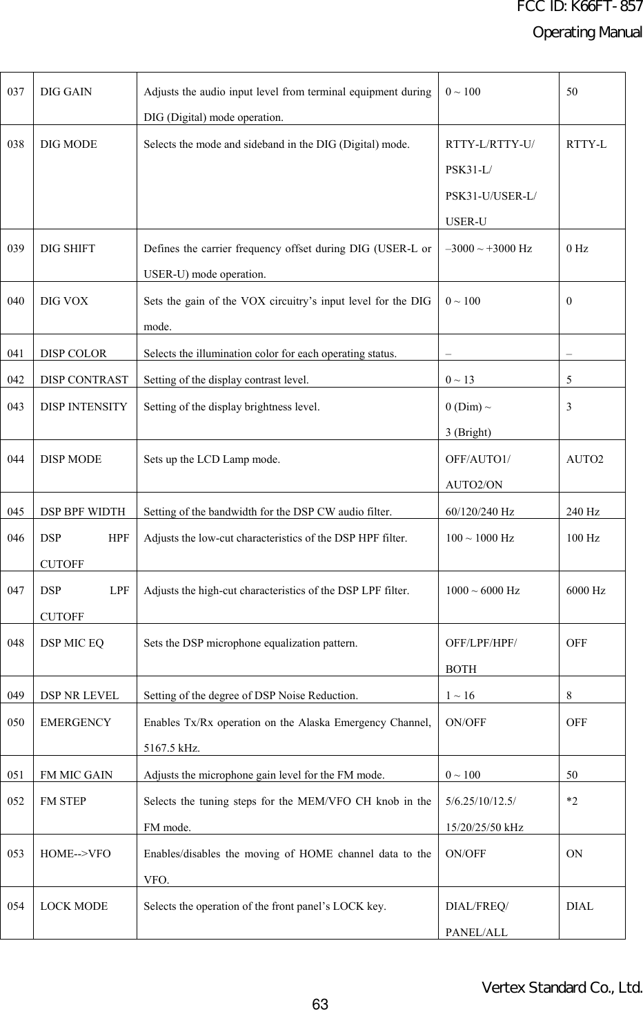
![FCC ID: K66FT-857Operating ManualVertex Standard Co., Ltd.64055 MEM GROUP Enables/disables the memory grouping feature. ON/OFF OFF056 MEM TAG Stores Alpha-Numeric “Tags” for the memory channels. – –057 MEM/VFO DIALMODESelects the function which is engaged when you press theMEM/VFO CH knob.W SIDETONE,CW SPEED,MHz/MEM GRP,MIC GAIN,NB LEVEL,RF POWER,STEPMHz/MEM GRP058 MIC SCAN Enables/disables scanning access via the microphone’s[UP]/[DWN] keys.ON/OFF ON059 MIC SEL The choice of the equipment which connects to the MIC jack. NOR/RMT/CAT NOR060 MTR ARX SEL Select the meter display configuration while the transceiver isreceiving.SIG, CTR, VLT, N/A,FS, OFFSIG061 MTR ATX SEL Selects the meter display configuration while the transceiveris transmitting.PWR, ALC, MOD,SWR, VLT, N/A, OFFPWR062 MTR PEAKHOLDEnabling/disabling of the “peak hold” function of the meter. ON/OFF ON063 NB LEVEL Setting of the blanking level for the IF Noise Blanker. 0 ~ 100 50064 OP FILTER 1 Not available at this time. – –065 PG A Programming the [A] key (in the Operating Function Row 17)function.MONI066 PG B Programming the [B] key (in the Operating Function Row 17)function.Q.SPL067 PG C Programming the [C] key (in the Operating Function Row 17)function.All Multi Function, allMenu Item, MONI,Q.SPL, TCALL, ATCand USER.ATC068 PG ACC Not available at this time. – –069 PG P1 Not available at this time. – –070 PG P2 Not available at this time. – –071 PKT 1200 Adjusts the audio input level from the TNC during 1200 bpsPacket operation.0 ~ 100 50072 PKT 9600 Adjusts the audio input level from the TNC during 9600 bpsPacket operation.0 ~ 100 50](https://usermanual.wiki/Yaesu-Musen/FT-857/User-Guide-286869-Page-64.png)
 key.OFF/ATAS(HF)/ATAS(HF&50)/ATAS(ALL)/TUNEROFF086 TX IF FILTER Selects the Transmit IF filter. CFIL/FIL1/FIL2 CFIL087 VOX DELAY Sets the “hang time” for the VOX circuitry. 100 ~ 3000 (ms) 500 ms088 VOX GAIN Sets the gain of the VOX circuitry’s input audio detector. 1 ~ 100 50089 XVTR A FREQ –090 XVTR B FREQAllows an arbitrary frequency to be set on the display, toallow direct frequency readout during transverter operation.00,000,00 ~ 99,999,99(kHz) –091 XVTR SEL Enables/disables/selects the antenna port to be used forTransverter operation.OFF/X VTR A/X VTR BOFF*1: Depends Mon transceiver version.* 2: Depends on operating band and transceiver version.](https://usermanual.wiki/Yaesu-Musen/FT-857/User-Guide-286869-Page-65.png)
![FCC ID: K66FT-857Operating ManualVertex Standard Co., Ltd.66MENU MODE No-001 [EXT MENU]Function: Enables/Disables the extended Menu Mode.Available Values: ON/OFFDefault: OFFMENU MODE Nox002 [144 MHz ARS]Function: Activates/deactivates the Automatic Repeater Shift feature when operating on the 144 MHz band.Available Values: ON/OFFDefault: ON (depending on transceiver version)MENU MODE Nox003 [430 MHz ARS]Function: Activates/deactivates the Automatic Repeater Shift feature when operating on the 430 MHz band.Available Values: ON/OFFDefault: ON (depending on transceiver version)MENU MODE Nox004 [AM&FM DIAL]Function: Enabling/disabling of the DIAL knob on the AM and FM modes.Available Values: ENABLE/DISABLEDefault: DISABLEMENU MODE No-005 [AM MIC GAIN]Function: Adjusts the microphone gain level for the AM mode.Available Values: 0 ~ 100Default: 50MENU MODE No-006 [AM STEP]Function: Selects the tuning steps for the MEM/VFO CH knob on the AM mode.Available Values: 2.5/5/9/10/12.5/25kHzDefault: 5 kHz (depending on transceiver version)MENU MODE No-007 [APO TIME]Function: Selects the Auto Power Off time (time before power goes off).Available Values: OFF/1h ~ 6h](https://usermanual.wiki/Yaesu-Musen/FT-857/User-Guide-286869-Page-66.png)
![FCC ID: K66FT-857Operating ManualVertex Standard Co., Ltd.67Default: OFFMENU MODE Nox008 [ARTS BEEP]Function: Selects the ARTS beep mode.Available Values: OFF/RANGE/ALLDefault: RANGEOFF: No alert beeps sound; you must look at the display to determine current ARTS status.RANGE: A high tone beep will sound when the transceiver first detects that you are within range, and a low beep willsound when the other station goes out of range.ALL: A high tone beep will sound every time a polling transmission is received from the other station, and a lowbeep will sound once when the other station goes out of range.MENU MODE Nox009 [ARTS ID]Function: Enables/disables the CW identifier during ARTS operation.Available Values: ON/OFFDefault: OFFMENU MODE Nox010 [ARTS IDW]Function: Stores your callsign into the CW identifier. Up to ten characters may be stored. The storage procedure is asfollows:1. Press the MEM/VFO CH knob momentarily to initiate callsign storage (the first character location ofthe callsign will be underlined).2. Rotate the DIAL knob to select the first letter/number of your callsign, then rotate the MEM/VFO CH knob one clickclockwise to save the first letter/number and move to the next entry position.3. Repeat the previous step as many times as necessary to complete your callsign.4. Press the MEM/VFO CH knob to save your completed callsign and exit.Default: YAESUMENU MODE Nox011 [BEACON TEXT 1]Function: Stores the message for the Beacon. Up to 40 characters may be stored. The storage procedure is as follows:1. Press and hold in the [F] key for one second to enter the Menu mode.2. Rotate the MEM/VFO CH knob to select Menu Mode No-011 [BEACON TEXT 1].3. Press the MEM/VFO CH knob to enable storage of the Beacon Text (the first character location will be underlined).4. Rotate the DIAL to select the first character (number or letter) in the Beacon Text you wish to store, then rotate the](https://usermanual.wiki/Yaesu-Musen/FT-857/User-Guide-286869-Page-67.png)
![FCC ID: K66FT-857Operating ManualVertex Standard Co., Ltd.68MEM/VFO CH knob one click clockwise to move to the next character.5. Repeat step 4 as many times as necessary to complete the Beacon Text.If the Beacon Text is less than 40 characters or more than 40 characters, see page 50 for details.MENU MODE Nox012 [BEACON TIME]Function: Selects the interval time (between message and message).Available Values: OFF/1 sec ~ 255 secDefault: OFFMENU MODE Nox013 [BEEP TONE]Function: Selects the beep frequency.Available Values: 440/880/1760 HzDefault: 880 HzMENU MODE No-014 [BEEP VOL]Function: Selects the beep volume level.Available Values: 0 ~ 100Default: 50Press the [B] key to monitor the level during adjustment.MENU MODE Nox015 [CAR LSB R]Function: Sets the Rx Carrier Point for LSB.Available Values: –300 ~ +300 HzDefault: 0 HzMENU MODE Nox016 [CAR LSB T]Function: Sets the Tx Carrier Point for LSBAvailable Values: –300 ~ +300 HzDefault: 0 HzMENU MODE Nox017 [CAR USB R]Function: Sets the Rx Carrier Point for USBAvailable Values: –300 ~ +300 Hz](https://usermanual.wiki/Yaesu-Musen/FT-857/User-Guide-286869-Page-68.png)
![FCC ID: K66FT-857Operating ManualVertex Standard Co., Ltd.69Default: 0 HzMENU MODE Nox018 [CAR USB T]Function: Sets the Tx Carrier Point for USBAvailable Values: –300 ~ +300 HzDefault: 0 HzMENU MODE Nox019 [CAT RATE]Function: Sets the transceiver’s circuitry for the CAT baud rate to be used.Available Values: 4800bps/9600bps/38400bpsDefault: 4800bpsMENU MODE Nox020 [CAT/LIN/TUN]Function: Selects the device which is connected to the CAT/LINEAR jack on the rear panel.Available Values: CAT/LINEAR/TUNERDefault: CATMENU MODE Nox021 [CLAR DIAL SEL]Function: Defines the “control” knob to be used for setting of the clarifier offset frequency.Available Values: CLAR, M/V, MAIN (Clarifier/Selector/Main Dial Knobs)Default: CLARMENU MODE No-022 [CW AUTO MODE]Function: Selects whether the KEY jack shall be “Enabled” or “Disabled” while using the SSB/FM modes.Available Values: ON/OFFDefault: OFFOFF: The KEY jack is enabled on the CW mode only.ON: The KEY jack is enabled on all modes (SSB mode: A1, FM mode: F2). Thus, on SSB, you can ask a station fora CW QSO without having to change your FT-857’s Mode selection, if Menu #022 is set to “On.”MENU MODE Nox023 [CW BFO]Function: Sets the CW carrier oscillator injection side on the CW mode.Available Values: USB/LSB/AUTO](https://usermanual.wiki/Yaesu-Musen/FT-857/User-Guide-286869-Page-69.png)
![FCC ID: K66FT-857Operating ManualVertex Standard Co., Ltd.70Default: USBUSB: Injects the CW carrier oscillator on the USB sideLSB: Injects the CW carrier oscillator on the LSB sideAUTO: Injects the CW carrier oscillator on the LSB side while operating on the 10 MHz band and below, USB sidewhile operate on the 10 MHz band and up.MENU MODE No-024 [CW DELAY]Function: Sets the receiver recovery time during pseudo-VOX CW semi-break-in operation.Available Values: FULL/30 ~ 3000 msecDefault: 250 msecThe recovery time may be adjusted in steps of 10 msec. A longer delay may be preferable if you pause frequently whilesending.MENU MODE Nox025 [CW KEY REV]Function: Sets the keyer paddle’s wiring configuration.Available Values: NORMAL/REVERSEDefault: NORMALNORMAL: Keyer paddle polarity is normal. The “tip” plug connection produces dots, and the “ring” plug connectionproduces dashes.REVERSE: Keyer paddle polarity is inverted. The “tip” paddle produces dashes, and the “ring” paddle produces dots.MENU MODE Nox026 [CW PADDLE]Function: Enables/disables CW keying by the microphone’s [UP]/[DWN] keys.Available Values: ELEKEY/MICKEYDefault: ELEKEYWhen this Menu Item is set to “MICKEY,” press the microphone’s [UP] key to send a “d ot,” and press the microphone’s[DWN] key to send a “dash” (while the built-in electronic keyer is engaged).MENU MODE No-027 [CW PITCH]Function: Setting of the pitch of the CW sidetone, BFO offset, and CW filter center frequencies.Available Values: 400 ~ 800 HzDefault: 700 HzThe CW pitch may be adjusted in steps of 100 Hz.](https://usermanual.wiki/Yaesu-Musen/FT-857/User-Guide-286869-Page-70.png)
![FCC ID: K66FT-857Operating ManualVertex Standard Co., Ltd.71MENU MODE Nox028 [CW QSK]Function: Selects the time delay between when the PTT is keyed and the carrier is transmitted during QSK operationwhen using the internal keyer.Available Values: 10/15/20/25/30 msDefault: 10 msNote: If you select “25 (or 30) ms,” please do not attempt to set Menu [No-030 CW SPEED] to a speed faster than “50(42) wpm,” as the delay will make it impossible to transmit.MENU MODE No-029 [CW SIDE TONE]Function: Setting of the CW sidetone volume level.Available Values: 0 ~ 100Default: 50MENU MODE No-030 [CW SPEED]Function: Sets the sending speed for the built-in Electronic keyer.Available Values: 4wpm ~ 60 wpm (1wpm/step)/20cpm ~ 300 cpm (5cpm/step)Default: 12 wpm (60 cpm)You can set the sending speed according to either of two units of speed (wpm: words per minute; cpm: characters perminute)To switch units between “wpm” and “cpm,” just press the MEM/VFO CH knob.MENU MODE Nox031 [CW TRAINING]Function: Sends random Morse Code five-character groups via the sidetone.Available Values: N / A / ANDefault: NN: Numeric characters onlyA: Alphabet characters onlyAN: Numeric and Alphabet characters (Mixed)MENU MODE Nox032 [CW WEIGHT]Function: Sets the Dot:Dash ratio for the built-in electronic keyer.Available Values: 1:2.5 ~ 1:4.5](https://usermanual.wiki/Yaesu-Musen/FT-857/User-Guide-286869-Page-71.png)
![FCC ID: K66FT-857Operating ManualVertex Standard Co., Ltd.72Default: 1:3.0MENU MODE No-033 [DCS CODE]Function: Setting of the DCS code.Available Values: 104 Standard DCS codesDefault: 023You can set the DSC codes for Encode and Decode separately.To switch between “ENCODE” and “DECODE,” just press the MEM/VFO CH knob.MENU MODE Nox034 [DCS INV]Function: Selects “Normal” or “Inverted” DCS coding.Available Values: Tn-Rn/Tn-Riv/Tiv-Rn/Tiv-RivDefault: Tn-Rn“n” = “normal”“iv” = “inverted”MENU MODE No-035 [DIAL STEP]Function: Setting of the DIAL knob’s tuning speed.Available Values: FINE/COARSEDefault: FINEYou may choose between two speeds for the DIAL knob. Selecting “COARSE” doubles the tuning rate compared to thedefault value.FINE: 10 Hz/step @SSB/CW mode, 100 Hz/step @AM/FMCOARSE: 20 Hz/step @SSB/CW mode, 200 Hz/step @AM/FMMENU MODE Nox036 [DIG DISP]Function: Defines the displayed frequency offset during DIG (USER-L or USER-U) mode operation.Available Values: –3000 ~ +3000 HzDefault: 0 HzMENU MODE Nox037 [DIG GAIN]Function: Adjusts the audio input level from terminal equipment (such as a TNC or PSK-31 sound card) during DIG(Digital) mode operation.](https://usermanual.wiki/Yaesu-Musen/FT-857/User-Guide-286869-Page-72.png)
![FCC ID: K66FT-857Operating ManualVertex Standard Co., Ltd.73Available Values: 0 ~ 100Default: 50MENU MODE Nox038 [DIG MODE]Function: Selects the mode and sideband (if applicable) in the DIG (Digital) mode.Available Values: RTTY-L/RTTY-U/PSK31-L/PSK31-U/USER-L/USER-UDefault: RTTY-LRTTY-L: AFSK RTTY operation on the LSB modeRTTY-U:AFSK RTTY operation on the USB modePSK31-L: PSK-31 operation on the LSB modePSK31-U: PSK-31 operation on the USB modeUSER-L: User-programmed costume operation based on LSB modeUSER-U: User-programmed costume operation based on USB modeIn the USER-L and USER-U modes, you can define the display frequency offset and carrier frequency offset by MenuMode No-036 [DIG DISP] and No-039 [DIG SHIFT].MENU MODE Nox039 [DIG SHIFT]Function: Defines the carrier frequency offset during DIG (USER-L or USER-U) mode operation.Available Values: –3000 ~ +3000 HzDefault: 0 HzMENU MODE Nox040 [DIG VOX]Function: Sets the gain of the VOX circuitry’s input level for the DIG mode.Available Values: 0 ~ 100Default: 0Note: When you wish to use “DIG VOX,” press the [F] key momentarily, then rotate the MEM/VFO CH knob, until youreach Multi Function Row “d” [RPT, REV, VOX], then press the [C](VOX) key. The parentheses and “VOX”icon will disappear, signifying that the (SSB/AM/FM voice) VOX system has been turned off. Despite theseindicators having disappeared, the Digital Mode “VOX” system will still be active, allowing audio input from aTNC or sound card to engage the transmitter.MENU MODE No-041 [DISP COLOR]Function: Selects the illumination color for each operating status.](https://usermanual.wiki/Yaesu-Musen/FT-857/User-Guide-286869-Page-73.png)
![FCC ID: K66FT-857Operating ManualVertex Standard Co., Ltd.74Available Values: ARTS/BAND/FIX/MEMGRP/MODE/MTR/VFODefault: FIXMENU MODE No-042 [DISP CONTRAST]Function: Setting of the display contrast level.Available Values: 1 ~ 13Default: 5MENU MODE No-043 [DISP INTENSITY]Function: Setting of the display brightness level.Available Values: 0 (Dim) ~ 3 (Bright)Default: 3MENU MODE Nox044 [DISP MODE]Function: Sets up the LCD Lamp mode.Available Values: OFF/AUTO1/AUTO2/ONDefault: AUTO2OFF: Disables the LCD illumination.AUTO1: Illuminates the LCD for three seconds when any button is pressed, or if you rotate the MEM/VFO CH knob.AUTO2: Illuminates the LCD continuously while the FT-857 is operating on an external power supply. When using theFNB-78 internal battery in the AUTO2 mode, the LCD will light up for three seconds when any button ispressed, or if you rotate the MEM/VFO CH knob (identical to AUTO1 mode).ON: Illuminates the LCD continuously.MENU MODE No-045 [DSP BPF WIDTH]Function: Setting of the bandwidth for the DSP CW audio filter.Available Values: 60/120/240 HzDefault: 240MENU MODE No-046 [DSP HPF CUTOFF]Function: Adjusts the low-cut characteristics of the DSP HPF filter.Available Values: 100/160/220/280/340/400/460/520/580/640/700/760/820/880/940/1000 (Hz)Default: 100](https://usermanual.wiki/Yaesu-Musen/FT-857/User-Guide-286869-Page-74.png)
![FCC ID: K66FT-857Operating ManualVertex Standard Co., Ltd.75This Menu Item determines the low-cut frequency of the DSP HPF filter in the SSB, AM, and FM modes. Generally,acceptable voice fidelity will be obtained only if you do not set this parameter much above 400 Hz.MENU MODE No-047 [DSP LPF CUTOFF]Function: Adjusts the high-cut characteristics of the DSP LPF filter.Available Values:1000/1160/1320/1480/1650/1800/1970/2130/2290/2450/2610/2770/2940/3100/3260/3420/3580/3740/3900/4060/4230/4390/4550/4710/4870/5030/5190/5390/5520/5680/5840/6000 (Hz)Default: 6000This Menu Item determines the high-cut frequency of the DSP LPF filter in the SSB, AM, and FM modes. Best voice-mode interference rejection will usually be obtained with a setting of between 2130 and 2770 Hz.MENU MODE No-048 [DSP MIC EQ]Function: Sets the DSP microphone equalization pattern.Available Values: OFF/LPF/HPF/BOTHDefault: OFFOFF: This function is disabled.LPF: Lower frequencies are emphasized.HPF: Higher frequencies are emphasized.BOTH: Mid-range frequencies are emphasized.MENU MODE No-049 [DSP NR LEVEL]Function: Setting of the degree of DSP Noise Reduction.Available Values: 1 ~ 16Default: 8MENU MODE Nox050 [EMERGENCY]: USA Version onlyFunction: Enables Tx/Rx operation on the Alaska Emergency Channel, 5167.5 kHz.Available Values: ON/OFFDefault: OFFWhen this Menu Item is set to “ON,” the spot frequency of 5167.5 kHz will be enabled. To get to this frequency, use theMEM/VFO CH knob to navigate; the Alaska Emergency Channel will be found between the Memory channel “M-P20U”and “M-001.”Use of this frequency is restricted to amateurs operating in (or within 92.6 km of) the U.S. State of Alaska, and it is to be](https://usermanual.wiki/Yaesu-Musen/FT-857/User-Guide-286869-Page-75.png)
![FCC ID: K66FT-857Operating ManualVertex Standard Co., Ltd.76used for emergency communications only (involving the immediate protection of life or property).MENU MODE Nox051 [FM MIC GAIN]Function: Adjusts the microphone gain level for the FM mode.Available Values: 0 ~ 100Default: 50MENU MODE No-052 [FM STEP]Function: Selects the tuning steps for the MEM/VFO CH knob in the FM mode.Available Values: 5/6.25/10/12.5/15/20/25/50 kHzDefault: Depends on operating band and transceiver version.MENU MODE Nox053 [HOME ⇑ VFO]Function: Enables/disables the moving of HOME channel data to the VFO.Available Values: ON/OFFDefault: ONRecall the HOME channel, then rotate the “DIAL” or “MEM/VFO CH” knob.The data will now have been copied to the current VFO, although the original HOME contents will remain intact on thepreviously-stored HOME channel.MENU MODE Nox054 [LOCK MODE]Function: Selects the operation of the front panel’s LOCK key.Available Values: DIAL/FREQ/PANEL/ALLDefault: DIALDIAL: Locks the DIAL knob only.FREQ: Locks the front panel keys and knobs related to frequency control (such as BAND(UP) and BAND(DWN) key,[A](A/B) key., etc.)PANEL: Locks all front panel keys and knobs (except POWER and LOCK keys)ALL: Locks all front panel keys and knobs (except POWER and LOCK keys) and microphone keys.MENU MODE Nox055 [MEM GROUP]Function: Enables/disables the memory grouping feature.Available Values: OFF/ON](https://usermanual.wiki/Yaesu-Musen/FT-857/User-Guide-286869-Page-76.png)
![FCC ID: K66FT-857Operating ManualVertex Standard Co., Ltd.77Default: OFFWhen this Menu Item is set to “ON,” the 200 “standard” memory channels are partitioned into ten Memory Groups, eachholding up to 20 memory channels.MENU MODE Nox056 [MEM TAG]Function: Stores Alpha-Numeric “Tags” for the memory channels.Up to eight characters may be stored. The storage procedure is as follows:1. Recall the memory channel onto which you wish to appended a label.2. Press and hold in the [F] key for one second to enter the Menu mode.3. Rotate the MEM/VFO CH knob to recall Menu Mode No-056 [MEM TAG].4. Press the MEM/VFO CH knob to enable the programming of the label.5. Rotate the DIAL knob to select the first character (number, letter, or symbol) in the name you with to store, thenrotate the MEM/VFO CH knob clockwise to move to the next character.6. Again rotate the DIAL knob to select the next number, letter, or symbol, then rotate the MEM/VFO CH knobclockwise to move to the next character’s slot.7. Repeat step 6 as many times as necessary to complete the name tag for the memory, then press and hold in the [F] keyfor one second to save the A/N (Alpha-Numeric) name entry and exit to normal operation.8. During Memory operation, press the [F] key momentarily, then rotate the MEM/VFO CH knob, as needed, until MultiFunction Row “b” [MW, MCLR, TAG] appears on the display. Press the [C](TAG) key momentarily to activate thealpha-numeric Tag. Repeatedly pressing this key will toggle operation between “Frequency” display and “Tag”display.You can recall Menu Mode No-056 [MEM TAG] instantly by pressing and holding in the [C](TAG) key for one second.MENU MODE Nox057 [MEM/VFO DIAL MODE]Function: Selects the function which is engaged when you press the MEM/VFO CH knob.Available Values: CW SIDETONE, CW SPEED, MHz/MEM GRP, MIC GAIN, NB LEVEL, RF POWER/STEPDefault: MHz/MEM GRPMENU MODE Nox058 [MIC SCAN]Function: Enables/disables scanning access via the microphone’s [UP]/[DWN] keys.Available Values: OFF/ONDefault: ONMENU MODE Nox059 [MIC SEL]](https://usermanual.wiki/Yaesu-Musen/FT-857/User-Guide-286869-Page-77.png)
![FCC ID: K66FT-857Operating ManualVertex Standard Co., Ltd.78Function: The choice of the equipment which connects to the MIC jack.Available Values: NOR/RMT/CATDefault: NORNOR: Normal Microphone.RMT: Not available at this time.CAT: CAT system: if you are using the optional FC-30 antenna tuner, you can still use the CAT system by connectingthe serial Data cable to the MIC jack.MENU MODE Nox060 [MTR ARX SEL]Function: Select the meter display configuration while the transceiver is receiving.Available Values: SIG, CTR, VLT, N/A, FS, OFFDefault: SIGSIG: Indicates the incoming signal strength.CTR: Discriminator center meter.VLT: Indicates the battery voltage.N/A: Not available at this time.FS: Applies a calibration signal (1 mA for full scale) at the METER Jack on the transceiver bottom, for adjustment ofan external meter’s calibration.You may adjust the external potentiometer in your metering system so that the external meter reading is full scale.OFF: Disables the meter.MENU MODE Nox061 [MTR ATX SEL]Function: Selects the meter display configuration while the transceiver is transmitting.Available Values: PWR, ALC, MOD, SWR, VLT, N/A, OFFDefault: PWRPWR: Indicates the relative transmit power.ALC: Indicates the relative Automatic Level Control voltage.MOD: Indicates the deviation level.SWR: Indicates the Standing Wave Ratio (forward:reflected).VLT: Indicates the battery voltage.N/A: Not available at this time.OFF: Disables the meter.](https://usermanual.wiki/Yaesu-Musen/FT-857/User-Guide-286869-Page-78.png)
![FCC ID: K66FT-857Operating ManualVertex Standard Co., Ltd.79MENU MODE No-062 [MTR PEAK HOLD]Function: Enabling/disabling of the “peak hold” function of the meter.Available Values: OFF/ONDefault: ONMENU MODE No-063 [NB LEVEL]Function: Setting of the blanking level for the IF Noise Blanker.Available Values: 0 ~ 100Default: 50MENU MODE Nox064 [OP FILTER 1]Not available at this time.MENU MODE Nox065 [PG A]Function: Programming the [A] key (in the Operating Function Row 17) function.Available Values: All Multi Function , all Menu Item, MONI, Q.SPL, TCALL, ATC and USER.Default: MONIMENU MODE Nox066 [PG B]Function: Programming the [B] key (in the Operating Function Row 17) function.Available Values: All Multi Function , all Menu Item, MONI, Q.SPL, TCALL, ATC and USER.Default: Q.SPLMENU MODE Nox067 [PG C]Function: Programming the [C] key (in the Operating Function Row 17) function.Available Values: All Multi Function , all Menu Item, MONI, Q.SPL, TCALL, ATC and USER.Default: ATCMENU MODE Nox068 [PG ACC]Not available at this time.MENU MODE Nox069 [PG P1]Not available at this time.](https://usermanual.wiki/Yaesu-Musen/FT-857/User-Guide-286869-Page-79.png)
![FCC ID: K66FT-857Operating ManualVertex Standard Co., Ltd.80MENU MODE Nox070 [PG P2]Not available at this time.MENU MODE Nox071 [PKT1200]Function: Adjusts the audio input level from the TNC during 1200 bps Packet operation.Available Values: 0 ~ 100Default: 50MENU MODE Nox072 [PKT9600]Function: Adjusts the audio input level from the TNC during 9600 bps Packet operation.Available Values: 0 ~ 100Default: 50MENU MODE Nox073 [PKT RATE]Function: Sets the transceiver’s circuitry for the Packet baud rate to be used.Available Values: 1200/9600 (bps)Default: 1200 (bps)MENU MODE No-074 [PROC LEVEL]Function: Sets the compression level for the AF speech processor in the SSB/AM modes.Available Values: 0 ~ 100Default: 50MENU MODE No-075 [RF POWER SET]Function: Setting of the maximum power level for the current band.Available Values: 5 ~ 100Default: 100MENU MODE No-076 [RPT SHIFT]Function: Sets the magnitude of the repeater shift.Available Values: 0.00 ~ 99.99 (MHz)Default: Depends on operating band and transceiver version.](https://usermanual.wiki/Yaesu-Musen/FT-857/User-Guide-286869-Page-80.png)
![FCC ID: K66FT-857Operating ManualVertex Standard Co., Ltd.81MENU MODE Nox077 [SCAN MODE]Function: Selects the desired Scan-Resume mode.Available Values: TIME/BUSY/STOPDefault: TIMEThis Menu Item allows you to select your favorite method of scan-restart after the scanner has stopped on an incomingsignal (when the squelch opens).TIME: The scanner will hold for a fixed length of time, set via MENU MODE No-078 [SCAN RESUME], then resumewhether or not the other station is still transmitting.BUSY: The scanner will hold until the signal disappears, then will resume after one second.STOP: The scanner will stop when a signal is received, and will not restart.MENU MODE Nox078 [SCAN RESUME]Function: Sets the delay time for scanning resumption.Available Values: 1 ~ 10 (sec)Default: 5MENU MODE Nox079 [SPLIT TONE]Function: Enables/disables split CTCSS/DCS cording.Available Values: OFF/ONDefault: OFFMENU MODE No-080 [SQL/RF GAIN]Function: Selects the configuration of the front panel’s SQL/RF knob.Available Values: RF-GAIN/SQLDefault: Depends on transceiver version.MENU MODE No-081 [SSB MIC GAIN]Function: Adjusts the microphone gain level for the SSB mode.Available Values: 0 ~ 100Default: 50MENU MODE No-082 [SSB STEP]](https://usermanual.wiki/Yaesu-Musen/FT-857/User-Guide-286869-Page-81.png)
![FCC ID: K66FT-857Operating ManualVertex Standard Co., Ltd.82Function: Selects the tuning steps for the MEM/VFO CH knob on the SSB mode.Available Values: 1kHz/2.5kHz/5kHzDefault: 2.5kHzMENU MODE No-083 [TONE FREQ]Function: Setting of the CTCSS Tone Frequency.Available Values: 50 Standard CTCSS tonesDefault: 88.5 HzMENU MODE No-084 [TOT TIME]Function: Select the Automatic Power Off time.Available Values: OFF/1 ~ 20 (min)Default: OFFMENU MODE Nox085 [TUNER/ATAS]Function: Selects the device (FC-30 or ATAS-100/-120) to be controlled via the front panel’s [A](TUNE) key.Available Values: OFF/ATAS(HF)/ATAS(HF&50)/ATAS(ALL)/TUNERDefault: OFFOFF: The [A](TUNE) key is disabled.ATAS (HF): The [A](TUNE) key will activate the optional ATAS-100/-120 on the HF amateur bands.ATAS (HF&50): The [A](TUNE) key will activate the optional ATAS-100/-120 on the HF amateur bands and 50MHz amateur band.ATAS (ALL): The [A](TUNE) key will activate the optional ATAS-100/-120 on the all amateur bands whichenable to the FT-857 transceiver.TUNER: The [A](TUNE) key will activate the optional FC-30.MENU MODE Nox086 [TX IF FILTER]Function: Selects the Transmit IF filter.Available Values: CFIL/FIL1/FIL2Default: CFILMENU MODE Nox087 [VOX DELAY]Function: Sets the “hang time” for the VOX circuitry.](https://usermanual.wiki/Yaesu-Musen/FT-857/User-Guide-286869-Page-82.png)
![FCC ID: K66FT-857Operating ManualVertex Standard Co., Ltd.83Available Values: 100 ~ 3000 (ms)Default: 500 (ms)MENU MODE No-088 [VOX GAIN]Function: Sets the gain of the VOX circuitry’s input audio detector.Available Values: 1 ~ 100Default: 50MENU MODE Nox089 [XVTR A FREQ]Function: Allows an arbitrary frequency to be set on the display, to allow direct frequency readout during transverteroperation; can also be used to account for frequency conversion inaccuracies when a known reference frequency isknown.Available Values: 00,000,00 ~ 99,999,99 (kHz)Default: Current VFO frequency.MENU MODE Nox090 [XVTR B FREQ]Function: Allows an arbitrary frequency to be set on the display, to allow direct frequency readout during transverteroperation; can also be used to account for frequency conversion inaccuracies when a known reference frequency isknown.Available Values: 00,000,00 ~ 99,999,99 (kHz)Default: Current VFO frequency.MENU MODE Nox091 [XVTR SEL]Function: Enable/disable the Transverter function.Available Values: OFF/X VTR A/X VTR BDefault: OFFOFF: Disables the Transverter operation feature.X VTR A: Activates the transverter operation feature.The display frequency may be set via MENU No-089 [XVTR A FREQ].X VTR B: Activates the second transverter operation display.The display frequency may be set via MENU No-090 [XVTR B FREQ].](https://usermanual.wiki/Yaesu-Musen/FT-857/User-Guide-286869-Page-83.png)
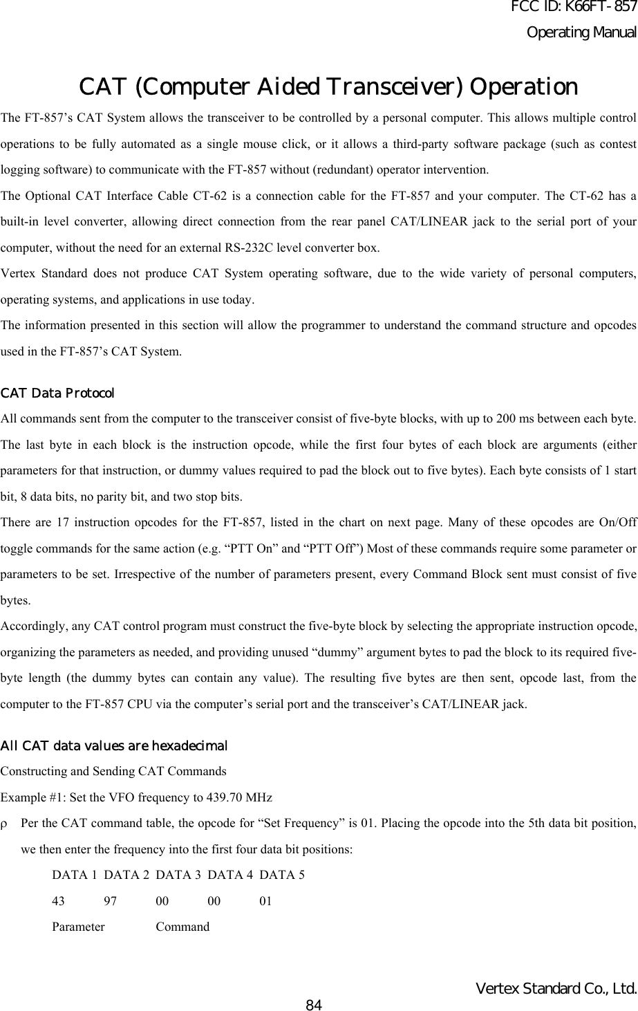
![FCC ID: K66FT-857Operating ManualVertex Standard Co., Ltd.85Send these five bytes to the transceiver, in the order shown above.Example #2: Turn the Split Mode “On”ρPer the CAT command table, the opcode for “Split On/off” is 02. Placing the opcode into the 5th data bit position, wethen enter dummy values into all other parameter locations:DATA 1 DATA 2 DATA 3 DATA 4 DATA 500 00 00 00 02Parameter CommandOpcode Command ChartCommand Title Parameter Opcode NotesLOCK ON/OFF * * * * CMD CMD = 00 : LOCK ONCMD = 80 : LOCK OFFPTT ON/OFF * * * * CMD CMD = 08 : PTT ONCMD = 88 : PTT OFFSet Frequency P1 P2 P3 P4 01 P1 ~ P4 : Frequency Digits01, 42, 34, 56, [01] = 14.23456 MHzOperating Mode P1 * * * 07 P1 = 00 : LSB,P1 = 01 : USB,P1 = 02 : CW, P1 = 03 : CWR,P1 = 04 : AM, P1 = 08 : FM,P1 = 0A : DIG, P1 = 0C : PKTP1 = 88 : FMNCLAR ON/OFF * * * * CMD CMD = 05 : CLAR ONCMD = 85 : CLAR OFFCLAR Frequency P1 * P3 P4 F5 P1 = 00 : “+” OFFSETP3, P4 : CLAR FrequencyP1 = 00 : “–” OFFSET12, 34 = 12.34 kHzVFO-A/B * * * * 81 ToggleSPLIT ON/OFF * * * * CMD CMD = 02 : SPLIT ONCMD = 82 : SPLIT OFFRepeater Offset P1 * * * 09 P1 = 09 : “–” SHIFTP1 = 49 : “+” SHIFT](https://usermanual.wiki/Yaesu-Musen/FT-857/User-Guide-286869-Page-85.png)
![FCC ID: K66FT-857Operating ManualVertex Standard Co., Ltd.86P1 = 89 : SIMPLEXRepeater Offset Frequency P1 P2 P3 P4 F9 P1 ~ P4 : Frequency Digits05, 43, 21, 00, [F9] = 5.4321 MHzCTCSS/DCS Mode P1 * * * 0A P1 = 0A : DCS ONP1 = 0B : DCS DECODER ONP1 = 0C : DCS ENCODER ONP1 = 2A : CTCSS ONP1 = 3A : CTCSS DECODER ONP1 = 4A : CTCSS ENCODER ONP1 = 8A : OFFCTCSS Tone P1 P2 P3 P4 0B P1 ~ P2 : CTCSS Tone Frequency for TX(Note 1)P3 ~ P4 : CTCSS Tone Frequency for RX(Note 1)DCS Code P1 P2 P3 P4 0C P1 ~ P2 : DCS Code for TX (Note 2)P3 ~ P4 : DCS Code for RX (Note 2)Read RX Status * * * * E7 (Note 3)Read TX Status * * * * F7 (Note 4)Read RX Status * * * * 03 (Note 5)Note 1: CTCSS ToneExample: Set the CTCSS Tone Frequncy to 88.5 Hz (TX) and 100.0 Hz (RX)P1 P2 P1 P208 85 10 00 = 88.5 Hz (TX), 100.0 Hz (RX)Note 2: DCS CodeExample: Set the DCS Code to 023 (TX) and 371 (RX)P1 P2 P1 P200 23 03 71 = 023 (TX), 371 (RX)Note 3: Read RX StatusNote 4: Read TX Status](https://usermanual.wiki/Yaesu-Musen/FT-857/User-Guide-286869-Page-86.png)
![FCC ID: K66FT-857Operating ManualVertex Standard Co., Ltd.87Note 5: Read Frequency & Mode StatusPower-on Microprocessor Reset ProceduresSome or all transceiver settings can be reset to their factory-default states using one of the following power-on routines:ρ[V/M] + POWER on: Resets all memories and following menu settings to their factory-default values:Menu #06 (AM STEP), 33 (DCS CODE), 52 (FM STEP), 56 (MEM TAG), 76 (RPT SHIFT), 82 (SSBSTEP), and 83 (TONE FREQ).ρ[F] + POWER on: Resets all menu settings (except the following menu items) to their factory-default values.Menu #06 (AM STEP), 33 (DCS CODE), 52 (FM STEP), 56 (MEM TAG), 76 (RPT SHIFT), 82 (SSBSTEP), and 83 (TONE FREQ).ρ[HOME] + POWER on: CPU master reset for all memories and menu settings.CloningYou can transfer all data stored in one transceiver to another set by utilizing the handy “Cloning” feature. This requires auser-constructed cloning cable which connects the CAT/LINEAR jacks on the two transceivers, as shown below.To clone from one transceiver to another, use the following procedure:1. Insert the Clone Cable into the CAT/LINEAR jack of each transceiver.2. Turn both transceivers off, then press and hold in the MODE(<) and MODE(>) buttons on each radio while turningthe power on again. The “CLONE MODE” notation will appear on the display.3. On the “d estination” radio, press the [C] key.4. Now, on the “source” radio, press the [A] key. Data will now be transferred to the “Destination” radio from the“Source” radio.5. If there is a problem during the cloning process, “error” will be displayed.Check your cable connections and try again.6. If cloning is successful, turn the “destination” radio off. Now turn the “source” radio off.7. Remove the clone cable. Channel and operating data for both radios are now identical. They both may be turned onnow for normal operation.Installation of Optional AccessoriesOptional Filters:YF-122S and YF-122C1. Turn the transceiver’s power off by pressing and holding in the PWR switch for one second, then disconnect the DCcable from the INPUT jack on the rear panel of the transceiver, when operating the FT-857 with a DC power supplyor optional FP-30 AC power supply.2. Referring to Figure 1, remove the eight screws affixing the top cover of the transceiver then disconnect the speaker’sconnector from the MAIN Unit.](https://usermanual.wiki/Yaesu-Musen/FT-857/User-Guide-286869-Page-87.png)
![FCC ID: K66FT-857Operating ManualVertex Standard Co., Ltd.883. Fold the top cover centering around the carrying hand side from the main chassis.4. Refer to Figure 2 for the mounting locations for the optional filters. Position the filter so that its connectors are alignedwith the mounting pins on the board, and push it into place (these slots does not distinction for the installed filter).5. Replace the top cover and its eight screws (remember to replace the internal speaker’s plug), then connect the DCcable to the INPUT jack when operating the FT-857 with a DC power supply or optional FP-30 AC power supply.6. Press the MEM/VFO CH knob momentarily, then rotate the DIAL knob to change the setting of menu to “2.3” (if youinstalled the YF-122S) or “500” (for YF-122C).7. Press and hold in the [F] key for one second to save the new set-up and exit to normal operation.8. Filter installation is now complete.To use the optional filter, press the [B](2.3 or 500) key (in Multi Function Row “n” [CFIL, 2.3 or 500, 2.3 or 500]) toactivate the optional filter which is installed in the “FIL1” slot. Press the [C](2.3 or 500) key (in Multi Function Row “n”[CFIL, 2.3 or 500, 2.3 or 500]) to activate the optional filter which is installed in the “FIL2” slot.Note: If you wish to use the optional filter for the TX IF filter while operating in the SSB mode, change the setting ofMenu Mode No-086 [TX IF FILTER] to “FIL1” or “FIL2” (the slot into which you installed the optional YF-122S filter).Optional High Stability Reference Oscillator TCXO-9Optional High Stability Reference Oscillator TCXO-9The TCXO-9 provides high stability over a wide range of ambient temperatures, so as to enhance digital-mode operating.1. Turn the transceiver’s power off by pressing and holding in the POWER switch for one second, then disconnect theDC cable from the INPUT jack on the rear panel of the transceiver, when operating the FT-857 with a DC powersupply or optional FP-30 AC power supply.2. Referring to Figure 1, remove the eight screws affixing the top cover of the transceiver then disconnect the speaker’sconnector from the MAIN Unit.3. Fold the top cover centering around the carrying hand side from the main chassis.4. Referring to Figure 2, locate the factory-installed REF UNIT on the board. Remove the factory-installed REF UNITfrom the board, then position the TCXO-9 so that its connectors are aligned with the mounting pins on the board, andpush it into place.5. Replace the top case (remember to replace the internal speaker’s plug).6. TCXO-9 installation is now complete. Connect the DC cable to the INPUT jack when operating the FT-857 with a DCpower supply or optional FP-30 AC power supply.AppendixSetup of Memories for Low Earth Orbit (LEO) FM Satellite OperationAlthough the FT-857 is not capable of “full duplex” operation (simultaneous transmission and reception), its flexible](https://usermanual.wiki/Yaesu-Musen/FT-857/User-Guide-286869-Page-88.png)
![FCC ID: K66FT-857Operating ManualVertex Standard Co., Ltd.89memory system is ideal for configuring a set of memories for LEO satellite work.The example below is designed around the popular satellite UO-14, but the same principles apply to operation using AO-27, SO-35, and other such satellites.First, set up a table of the required operating frequencies. For UO-14, a typical setup table is shown below:Channel # Rx Freq. Tx Freq. Notes1 435.080 145.970.0 AOS2 435.075 145.972.53 435.070 145.975.0 Mid Pass4 435.065 145.977.55 435.060 145.980.0 LOSAOS = Acquisition of Signal (Beginning of Pass)LOS = Loss of Signal (End of Pass)The above frequencies are nominal, and the changing frequencies reflects the Doppler Shift which occurs on suchsatellites, which display rapid apparent motion relative to an earth-based observer. But if we can accommodate a set ofseveral frequency pairs in our memory system, frequencies that reflect the frequency relationships encountered during atypical pass, we will have a good chance of having our frequencies properly aligned when it is time for making a QSO.So we need to store the above frequency matrix into memories. Note that the receiving frequency and transmittingfrequency are on different bands. Therefore, we will use the “Split Frequency Memory” storage technique described onpage 42.First, press the [F] key momentarily, then rotate the MEM/VFO CH knob to select Multi Function Row “a” [A/B, A=B,SPL]. Press the [A](A/B) key, if necessary, to select VFOa.Now press the BAND(DWN) or BAND(UP) key to select the 70 cm band. Check the setting of Menu Mode No-004[AM&FM DIAL]. and set this to “ENABLE” to allow smaller frequency increments to be accommodated.Set the VFOa operating frequency to 435.0800.00 MHz. Now press the [A](A/B) key in Multi Function Row “a” to selectVFOb, and set VFOb to 145.970.00 MHz. Again press the [A](A/B) key to return to VFOa. Be sure that both VFOs areset to the FM mode, as well.Press the [F] key momentarily, and rotate the MEM/VFO CH knob one click clockwise to select Multi Function Row“b”[MW, SKIP, TAG].Press the [A](MW) key momentarily, then rotate the MEM/VFO CH knob while the memory channel number is blinking;select memory channel M-001, then press and hold in the [A](MW) key until you hear the double beep. We have juststored the first downlink (earth station receiving) frequency into memory.Press the [F] key momentarily, then rotate the MEM/VFO CH knob one click counter-clockwise to re-select Multi](https://usermanual.wiki/Yaesu-Musen/FT-857/User-Guide-286869-Page-89.png)
![FCC ID: K66FT-857Operating ManualVertex Standard Co., Ltd.90Function Row “a” [A/B, A=B, SPL]. Press the [A](A/B) key to select VFOb (145.970 MHz).Again press the [F] key momentarily, and rotate the MEM/VFO CH knob one click clockwise to re-select Multi FunctionRow “b” [MW, SKIP, TAG]. Press the [A](MW) key momentarily; the “M-001” indicator will flash; press and hold in themicrophone’s PTT key, and while holding it in press the [A](MW) key until you hear the double beep. You have nowstored the uplink (earth station transmitting) frequency into the same memory register as we did previously for thedownlink frequency.It’s now time to store the other frequencies in the matrix. Return to Multi Function Row “a” [A/B, A=B, SPL], and pressthe [A](A/B) key to return to VFOa on 435.080.00 MHz. Now rotate the DIAL knob to set the frequency to 435.075.00MHz. Press the [A](A/B) key again to select VFOb (145.970 MHz), and rotate the DIAL knob to set the frequency to145.972.50 MHz. Press the [A](A/B) key to return to VFOa on 435.075.00 MHz.Return to Multi Function “b” [MW, SKIP, TAG], and repeat the Split Memory storage process, selecting memory channelM-002 this time when initially storing the 435.075 MHz receiving frequency.Now repeat this entire process three more times, filling memory channels M-003, M-004, and M-005 with the frequenciesshown in the chart above.When it’s time to operate, press the [V/M] key, if necessary, to recall the Memory mode, and rotate the MEM/VFO CHknob to select channel M-001. This will be the first frequency pair to be utilized during the UO-14 window of workabilitywhen it rises above your local horizon. The Doppler effect will cause the nominal 435.070 MHz downlink frequency toappear higher to you, so utilize memory channel M-001 when the satellite first rises. A few minutes later, switch to M-002,and at mid-pass switch to M-003. As the satellite recedes, switch to M-004 and then M-005 toward the end of the pass.The MEM/VFO CH knob recall of these five channels makes Doppler tracking simple; just choose the memory channelproducing the best signal! You have already programmed an uplink frequency corresponding to the optimum downlinkfrequency, so you will not need to try to make difficult VFO adjustments during the brief satellite passes.The FM passbands used on LEO satellites are sufficiently broad that more precise frequency adjustment is not needed.To aid in channel identification, remember that you can use Menu Mode No-056 [MEM TAG] to label each satellitememory (for example, “UO-14a” ~ “UO-14e” for the above five channels).A complete set of frequencies may be stored for each LEO satellite you wish to utilize, and once configured, the FT-857provides a flexible and easy-to-use earth station capability for these popular satellites.](https://usermanual.wiki/Yaesu-Musen/FT-857/User-Guide-286869-Page-90.png)