Yaesu Musen FT-897 Scanning Receiver User Manual users manual
Yaesu Musen Co., Ltd. Scanning Receiver users manual
UserManual.wiki
>
Yaesu Musen
>
FT-897 User Manual
>
users manual
Contents
1.
users manual
2.
compliance statement for fcc
users manual
Navigation menu
Upload a User Manual
Namespaces
Wiki Guide
HTML
PDF
Info
Views
User Manual
Discussion / Help
Navigation
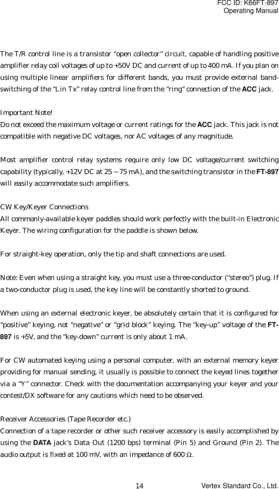
![FCC ID: K66FT-897Operating ManualVertex Standard Co., Ltd.13Heat and VentilationTo ensure long life of the components, be certain to provide adequate ventilation aroundthe cabinet of the FT-897. The cooling system of the transceiver must be free to draw coolair in from the side of the transceiver and expel warm air from the rear of thetransceiver.Do not install the transceiver on top of another heat-generating device (such as a linearamplifier), and do not place equipment, books, or papers on top of the transceiver. Placethe transceiver on a hard, flat, stable surface. Avoid heating vents and window locationsthat could expose the transceiver to excessive direct sunlight, especially in hot climates.Linear Amplifier InterfacingThe FT-897 provides the switching and drive-control lines required for easy interfacingto most all commonly-available amplifiers sold today.These include: The Antenna Jacks (“HF/50MHz” and “144/430MHz”); A T/R control line (open circuit on RX, closure to ground on TX); and A negative-going ALC jack (control voltage range: 0V to –4V DC). When interfacing to the VL-1000 Solid State 1 KW Linear Amplifier, theoptional CT-58 Interface Cable provides for easy interconnection (requires thatthe Menu Mode No-80 [SIO MODE] setting changes to “LINEAR”).The rear-panel ACC jack is a miniature stereo type, which accepts ALC control voltageinput on the tip connection, and T/R control on the ring connection. The main shaft isused for the ground connection.Typical amplifier interface circuits are shown below.Note that some amplifiers, particularly VHF or UHF “brick” amplifiers, offer twomethods of T/R switching: application of +13V or a closure to ground.Be sure to configure your amplifier so that it switches via a closure to ground, asprovided by your FT-897. Alternatively, many of these amplifiers use “RF Sensing” tocontrol their relays; if yours is not in this category, you may then use the T/R control linefrom the ring of the ACC jack for control of your HF linear amplifier, if desired.](https://usermanual.wiki/Yaesu-Musen/FT-897.users-manual/User-Guide-242540-Page-13.png)
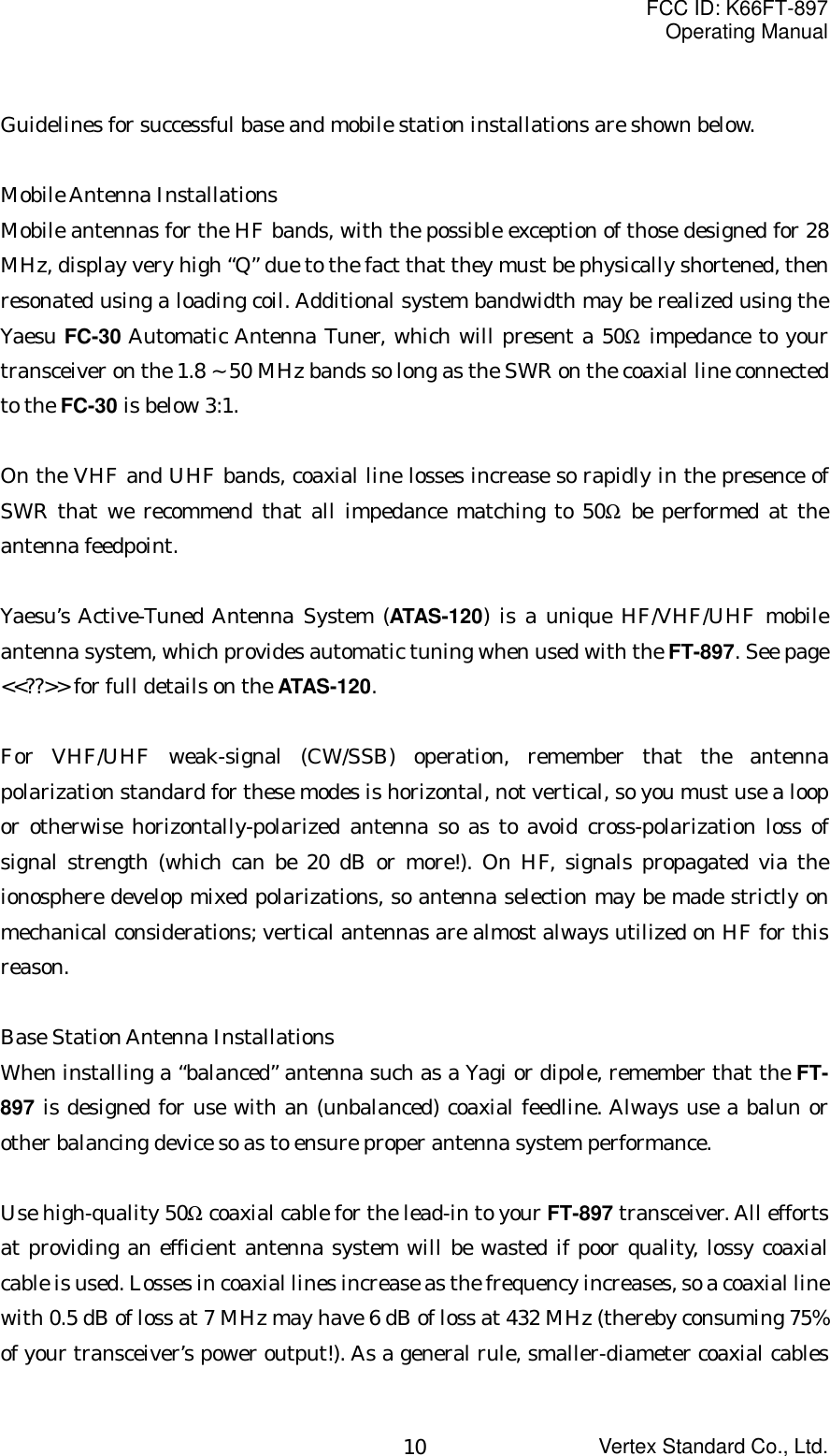
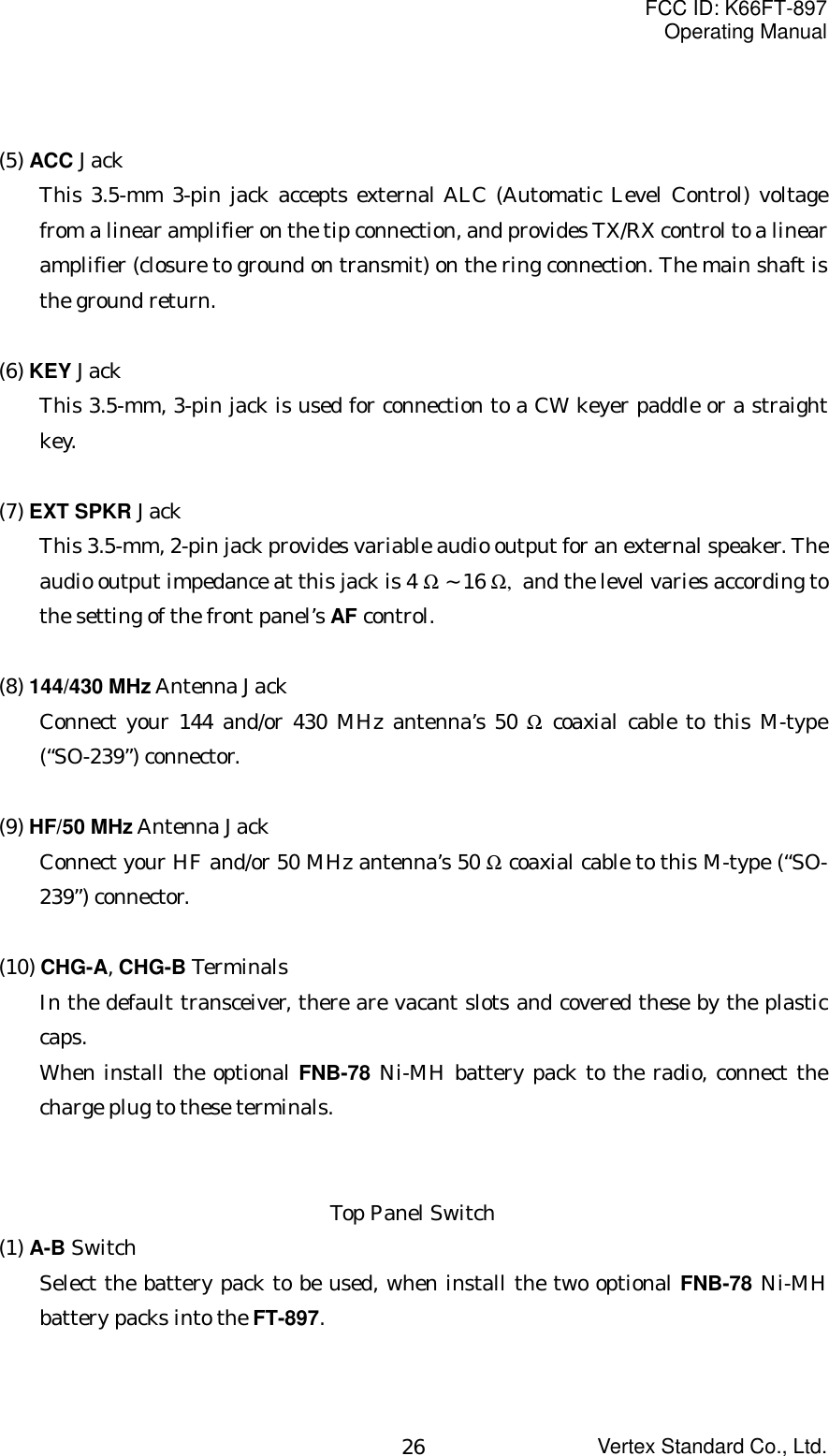
![FCC ID: K66FT-897Operating ManualVertex Standard Co., Ltd.15Adjusting the Front FeetThe two front feet of the transceiver allow the transceiver to be tilted upward for betterviewing. Simply fold both feet forward to raise the front of the transceiver, and fold themback against the bottom case to lower the front of the FT-897.Front Panel Control & Switches(1) Liquid Crystal DisplayThe Liquid Crystal Display (LCD) provides indication of the operating frequencyand other aspects of transceiver status. (2) FUNC KeysThese three keys select many of the most important operating features of thetransceiver. When press the [F] key then rotating the MEM/VFO CH knob; thecurrent function of that key (appeared above each of the [A], [B], and [C] keys (alongthe bottom of the LCD)) scrolls the display through 17 rows of functions availablefor use via the [A], [B], and [C] keys.The available features are shown in chart below.Multi Function Row “a” (MFa) [A/B, A=B, SPL][A] Key: A/BPress the [A](A/B) key to switch between VFO-A and VFO-B on the display.[B] Key: A=BPress and hold in the [B](A=B) key for one second to copy the contents of VFO-A intothe VFO-B register, so that the two VFOs’ contents will be identical.[C] Key: SPLPress the [C](SPL) key to activate Split frequency operation between VFO-A andVFO-B.Multi Function Row “b” (MFb) [MW, MC, TAG][A] Key: MWPress and hold in the [A](MW) key for one second to transfer the contents of the VFO](https://usermanual.wiki/Yaesu-Musen/FT-897.users-manual/User-Guide-242540-Page-15.png)
![FCC ID: K66FT-897Operating ManualVertex Standard Co., Ltd.16into a Memory register.[B] Key: MCPress the [B](MC) key to designate the current Memory channel to be “skipped”during scanning.[C] Key: TAGPress the [C](TAG) key to select the display type (Frequency or Alpha-numeric Tag)during Memory operation.Multi Function Row “c” (MFc) [STO, RCL, PROC][A] Key: STOPress the [A](STO) key to store the contents of the VFO into the QMB (QuickMemory Bank) register.[B] Key: RCLPress the [B](RCL) key to recall the QMB Memory.[C] Key: PROCPress the [C](PROC) key to activate the speech processor for SSB transmission.Press and hold in the [C](PROC) key for one second to recall Menu Mode No-074[PROC LEVEL] (for setting the compression level of the AF Speech Processor).Multi Function Row “d” (MFd) [RPT, REV, VOX][A] Key: RPTPress the [A](RPT) key to select the direction of the uplink frequency shift (+, –, orsimplex) during FM repeater operation.Press and hold in the [A](RPT) key for one second to recall Menu Mode No-076 [RPTSHIFT] (for setting the shift frequency offset).[B] Key: REVPress the [B](REV) key to reverse the transmit and receive frequencies whileworking through a repeater.[C] Key: VOXPress the [C](VOX) key enable the VOX (voice-operated transmitter switching](https://usermanual.wiki/Yaesu-Musen/FT-897.users-manual/User-Guide-242540-Page-16.png)
 key for one second to recall Menu Mode No-090 [VOXGAIN] (for setting the VOX gain level).Multi Function Row “e” (MFe) [TON/ENC, ----/DEC, TDCH][A] Key: TON/ENCPress the [A](TON) key to activate the CTCSS or DCS operation.When the Split Tone feature is activated via the Menu Mode No-85 [TONE SPLIT],this key function changes to “ENC.” Press the [A](ENC) key to activate the CTCSSencoder or DCS encoder.Press and hold the [A](TON/ENC) key for one second to recall the Menu Mode No-084 [TONE FREQ] (for selecting the CTCSS tone frequency).[B] Key: ----/DECNormally, this key is No Action.When the Split Tone feature is activated via the Menu Mode No-85 [TONE SPLIT],this key function changes to “DEC.” Press the [B](DEC) key to activate the CTCSSdecoder or DCS decoder.Press and hold the [B](DEC) key for one second to recall the Menu Mode No-032[DCS CODE] (for selecting the DCS code).[C] Key: TDCHPress the [C](TDCH) key to initiate the Tone or DCS Search.Multi Function Row “f” (MFf) [ARTS, SRCH, PMS][A] Key: ARTSPress the [A](ARTS) key to initiate the Auto-Range Transponder mode.Press and hold the [A](ARTS) key for one second to recall the Menu Mode No-008[ARTS BEEP] (for selecting the ARTS “Beep” option).[B] Key: SRCHPress the [B](SRCH) key to activate the Smart Search feature.Press and hold in the [B](SRCH) key for one second to initiate the Smart Search.[C] Key: PMSPress the [C](PMS) key to activate the Programmable Memory Scan feature.](https://usermanual.wiki/Yaesu-Musen/FT-897.users-manual/User-Guide-242540-Page-17.png)
![FCC ID: K66FT-897Operating ManualVertex Standard Co., Ltd.18Multi Function Row “g” (MFg) [SCN, PRI, DW][A] Key: SCNPress the [A](SCN) key to initiate the Scanning (in the direction of higherfrequencies).[B] Key: PRIPress the [B](PRI) key to activate the Priority Scan.[C] Key: DWPress the [C](DW) key to activate the Dual Watch feature.Multi Function Row “h” (MFh) [SSM, WIDH, STEP][A] Key: SSMPress the [A](SSM) key to activate the Spectrum Scope Monitor feature.Press and hold in the [A](SSM) key for one second to initiate the Spectrum Scope.[B] Key: WIDHPress the [B](WIDH) key to select the visible bandwidth for the Spectrum ScopeMonitor.Press and hold the [B](WIDH) key for one second to select the operating mode for theSpectrum Scope Monitor.[C] Key: STEPPress the [C](STEP) key to select the channel steps for Spectrum Scope Monitor.Press and hold in the [C](STEP) key for one second to activate the MAX HOLDfeature, which is holding the maximum signal strength level for each channels.Multi Function Row “i” (MFi) [MTR, ----, DISP][A] Key:Pressing the [A](MTR) key repeatedly allows selection of the display function of themeter in the transmit mode.PWR Æ ALC Æ SWR Æ MOD Æ PWR …The selected function is appeared above the [B] key.Press and hold the [A](MTR) key for one second to recall the Menu Mode No-060[MTR PEAK HOLD] (for setting the “Peak-Hold” function of the meter).](https://usermanual.wiki/Yaesu-Musen/FT-897.users-manual/User-Guide-242540-Page-18.png)
![FCC ID: K66FT-897Operating ManualVertex Standard Co., Ltd.19[B] Key:Pressing the [B] key repeatedly allows selection of the display function of the meterin the transmit mode.PWR Æ MOD Æ SWR Æ ALC Æ PWR …[C] Key: DISPPress the [C](DISP) key to switch the display between the Large Character andSmall Character modes.Multi Function Row “j” (MFj) [SPOT, BK, KYR][A] Key: SPOTPress the [A](SPOT) key to activate the CW receiver spotting heterodyne oscillator.[B] Key: BKPress the [B](BK) key to activate the CW “Semi” break-in operation.Press and hold in the [B](BK) key for one second to recall the Menu Mode No-023[CW DELAY] (for setting the CW delay time).[C] Key: KYRPress the [C](KYR) key to activate the built-in Electronic Keyer.Press and hold in the [C](KYR) key for one second to recall the Menu Mode No-029[CW SPEED] (for setting the Keyer speed).Multi Function Row “k” (MFk) [TUN, SHRT, EXTD][A] Key: TUNPress the [A](TUN) key to activate the optional Automatic Antenna Tuner or ActiveTuning Antenna System.Press and hold in the [A](TUN) key for one seconds to initiate tuner or antennaretuning.[B] Key: SHRTPress and hold in the [B](SHRT) key to lower the ATAS-120 antenna.[C] Key: EXTDPress and hold in the [C](EXTD) key to raise the ATAS-120 antenna.](https://usermanual.wiki/Yaesu-Musen/FT-897.users-manual/User-Guide-242540-Page-19.png)
![FCC ID: K66FT-897Operating ManualVertex Standard Co., Ltd.20Multi Function Row “l” (MFl) [NB, AGC, ----][A] Key:Press the [A](NB) key to activate the receiver’s IF Noise Blanker.Press and hold in the [A](NB) key for one second to recall the Menu Mode No-63 [NBLEVEL] (for setting of the NB level).[B] Key: AGCPress the [B](AGC) key to activate the receiver’s AGC system.[C] Key: AGCSPEEDPress the [C](AGCSPEED) key to select the recovery time (SLOW, FAST, or AUTO) forthe receiver’s AGC system.Multi Function Row “m” (MFm) [IPO, ATT, NAR][A] Key: IPOPress the [A](IPO) key to bypass the receiver preamplifier, thereby activatingIntercept Point Optimization for improved overload characteristics while operate onthe HF bands.Press the [A](IPO) key to activate the receiver preamplifier while operate on the 50MHz band.[B] Key: ATTPress the [B](ATT) key to engage the receiver front-end attenuator, which willreduce all signals and noise by approximately 10 dB.The ATT feature does not function on 144/430 MHz.[C] Key: NARPress the [C](NAR) key to selects the low-deviation mode required for HF FMoperation on 29 MHz.Multi Function Row “n” (MFn) [CERF, OPF1, OPF2][A] Key:Press the [A](CERF) key to select the 2.4 kHz ceramic IF filter.[B] Key:](https://usermanual.wiki/Yaesu-Musen/FT-897.users-manual/User-Guide-242540-Page-20.png)
 key to select the optional IF filter which is located on the“OPF1” slot on the Main Unit.When the optional filter is not installed on the“OPF1” slot, this key function isdisabled, and its label is “non.”[C] Key:Press the [C](OPF2) key to select the optional IF filter which is located on the“OPF2” slot on the Main Unit.When the optional filter is not installed on the“OPF2” slot, this key function isdisabled, and its label is “non.”Multi Function Row “o” (MFo) [PLY1, PLY2, PLY3][A] Key: PLY1Press the [A](PLY1) key to send the CW message which is memorized in the keyermemory channel 1.[B] Key: PLY2Press the [B](PLY2) key to send the CW message which is memorized in the keyermemory channel 2.[C] Key: PLY3Press the [C](PLY3) key to send the CW message which is memorized in the keyermemory channel 3.Multi Function Row “p” (MFp) [DNR, DNF, DBF][A] Key: DNRPress the [A](DNR) key to activate the DSP Noise Reduction system.Press and hold in the [A](DNR) key for one second recall the Menu Mode No-047[DSP NR LEVEL] (for setting the degree of DSP Noise Reduction).[B] Key: DNFPress the [B](DNF) key to activate the DSP’s Auto Notch Filter.[C] Key: DBFPress the [C](DBF) key to activate the DSP’s receiver Bandpass Filter.In the SSB, AM, FM, and AFSK modes, press and hold in the [C](DBF) key for one](https://usermanual.wiki/Yaesu-Musen/FT-897.users-manual/User-Guide-242540-Page-21.png)
![FCC ID: K66FT-897Operating ManualVertex Standard Co., Ltd.22second to recall Menu Mode No-050 [DSP HPF CUTOFF] (for adjust the high-frequency cutoff of the DSP Bandpass Filter).In the CW mode, press and hold in the [C](DBF) key for one second to recall MenuItem No-048 [DSP BPF WIDTH] (for setting the CW band width).Multi Function Row “q” (MFq) [PG A, PG B, PG C][A] Key: PG APress the [A](PG A) key to activate the user programmed function which isdetermined by the Menu Mode No-065 [PG A].[B] Key: PG BPress the [B](PG B) key to activate the user programmed function which isdetermined by the Menu Mode No-066 [PG B].[C] Key: PG CPress the [C](PG C) key to activate the user programmed function which isdetermined by the Menu Mode No-067 [PG C].*The Multi Function number (“MFa” ~ “MFq”) appears at the right bottom on theLCD.(3) MIC JackConnect the supplied MH-31 Hand Microphone to this jack.(4) PHONES JackThis 1/4-inch, 3-contact jack accept either monaural or stereo headphones with 2- or3-contact plugs. When a plug is inserted, the loudspeaker is disabled. The audiolevel varies according to the setting of the front panel’s AF knob.(5) PWR SwitchPress and hold in the PWR switch for one second to turn to the transceiver on or off.(6) F KeyPress this key momentarily to enable the changing of the function of the MultiFunction keys ([A], [B], and [C]) by the MEM/VFO CH knob.Press and hold this key for one second to activate the “Menu” mode.](https://usermanual.wiki/Yaesu-Musen/FT-897.users-manual/User-Guide-242540-Page-22.png)
![FCC ID: K66FT-897Operating ManualVertex Standard Co., Ltd.23(7) LOCK KeyPressing this key locks the front panel keys so as to prevent accidental frequencychange.(8) MAIN DIALThis is the main tuning dial for the transceiver. It is used both for frequency tuningas well as “Menu” setting in the transceiver. (9) SQL/RF KnobIn the USA version, this (outer) SQL/RF knob adjusts the gain of the receiver’s RFand IF stages. Using Menu Mode No-081 [SQL RF GAIN], this control may bechanged to function as a Squelch control, which may be used to silence backgroundnoise when no signal is present. In the other versions, its default setting is set to“Squelch.”(10) AF KnobThe (inner) VOL knob adjusts the receiver audio volume level presented to theinternal or external speaker. Clockwise rotation increases the volume level.(11) CLAR/IF SHIFT KeyPressing this key activates the Receiver Clarifier feature. When this feature isactivated, the CLAR knob is used to set a tuning offset of up to ±9.99 kHz. Thetransmitter’s frequency is not affected by the setting of the Clarifier.Press and hold this key for one second to activate the IF Shift feature, which allowsyou to use the MEM/VFO CH knob to adjust the center frequency of the IF filter’spassband response.(12) CLAR KnobThis knob tunes the clarifier offset frequency up to ±9.99 kHz, when the ReceiverClarifier feature is activated by pressing the CLAR/IF SHIFT key. (13) MEM/VFO CH KnobThis detented rotary switch is used for VFO frequency tuning, memory selection,and function selection for the [A], [B], [C] keys of the transceiver.This rotary switch is also used for adjust the center frequency of the IF filter’s](https://usermanual.wiki/Yaesu-Musen/FT-897.users-manual/User-Guide-242540-Page-23.png)
![FCC ID: K66FT-897Operating ManualVertex Standard Co., Ltd.24passband response, when the IF Shift feature is activated by press and holding theCLAR/IF SHIFT key for one second.(14) DSP ButtonPressing this button momentarily provides instant access to Multi Function Row “p”(MFp), which contains the command key for the receiver’s Digital Signal Processingsystem. The available functions will appear as the functions displayed above the [A],[B], and [C] keys, described previously.(15) HOME KeyPressing this key momentarily recalls a favorite “HOME” frequency memory.(16) V/M KeyPressing this key switches frequency control between the VFO and MemorySystems.(17) MODE(W)/MODE(X) KeyPressing either of these keys momentarily will change the operating mode. Theselections available are:… USB Ù LSB Ù CW Ù CWR Ù AM Ù DIG Ù PKT Ù USB …(18) BAND(DWN)/BAND(UP) KeyPressing either of these keys momentarily will cause the frequency to be moved upor down by one frequency band. The selections available are:… 1.8 MHz Ù 3.5 MHz Ù 7.0 MHz Ù 10 MHz Ù 14 MHz Ù 15 MHz Ù 18 MHz Ù24 MHz Ù 28 MHz Ù 50 MHz Ù 88 MHz Ù 108 MHz Ù 144 MHz Ù 430 MHz Ù1.8 MHz …(19) DSP IndicatorThis indicator glows green when the DSP feature is activated by pressing the DSPbutton.(20) TRANSMIT/BUSY IndicatorThis indicator glows green when the squelch opens, and turns red during transmit.](https://usermanual.wiki/Yaesu-Musen/FT-897.users-manual/User-Guide-242540-Page-24.png)
![FCC ID: K66FT-897Operating ManualVertex Standard Co., Ltd.25(21) CW-T IndicatorThis indicator glows green when the CW Training feature is activated via the MenuMode No-030 [CW TRAINING].(22) BATT-A, BATT-B IndicatorsThese LEDs indicate the battery status for the optional FNB-78 Ni-MH battery packwhile internal battery operation.The LED glows orange when the battery pack is waiting (switch to off by the A-Bswitch on the top panel), and turns orange when the is the battery pack en the radiooperate the corresponded battery pack by the A-B switch on the top panel. It alsoglows red during charging of the optional FNB-78 Ni-MH battery pack.Rear Panel Connectors(1) INPUT JackThis is the DC power supply connection for the transceiver, used when operating thetransceiver with an external power supply. Use the supplied DC cable to connectthis jack to the car battery or DC power supply, which must be capable of supplyingat least 22A @ 13.8 VDC. For base station operation, the optional FP-30 External ACpower supply attached to the bottom of the transceiver and connect the outputpigtail of the FP-30 to this jack.(2) GND TerminalFor best performance and safety, this Ground lug may be connected to a good earthground using a short, heavy, braided cable.(3) CAT/LINEAR JackThis 8-pin mini-DIN jack is used for connection to the FC-30 External AutomaticAntenna Tuner or ATAS-120 Active-Tuning Antenna System. It is also used forinterfacing to a personal computer for control of the transceiver using the CATsystem, and for interconnection to the VL-1000 Linear Amplifier.(4) DATA JackThis 6-pin, mini-DIN jack accepts AFSK input from a Terminal Node Controller(TNC); it also provides fixed-level Receiver Audio Output, Push-To-Talk (PTT),Squelch Status, and ground lines.](https://usermanual.wiki/Yaesu-Musen/FT-897.users-manual/User-Guide-242540-Page-25.png)
![FCC ID: K66FT-897Operating ManualVertex Standard Co., Ltd.28bands. See the “Stacked VFO System” discussion on page <<??> for details.Mode SelectionPress either the MODE(W) or MODE(X) key to move among the eight settings for theoperating modes, respectively.… LSB Ù USB Ù CW Ù CWR Ù AM Ù FM Ù DIG Ù PKT Ù LSB …R.F. Says: You can also set VFOa and VFOb to different modes in the same band,allowing you to have a “Phone” VFO and a “CW” VFO, for example.Adjusting the Audio Volume LevelRotate the AF knob to set a comfortable listening level.When operating in the “DIG” or “PKT” modes, you may set the AF knob to anycomfortable setting, or even all the way off, because the output from the DATA jack is afixed-level audio signal.R. F. Says: Start with the AF knob set fully counter-clockwise, especially when usingFM (the background noise on FM can be surprisingly loud)!Menu Quick StartMany aspects of this transceiver’s configuration may be customized using the convenient“Menu” system, which allow you to configure many “set and forget” settings just the wayyou want to. A full discussion of the Menu system beings on page <<??>>; for now, here isa brief discussion on how to change Menu settings:1. Press and hold in the [F] key for one second to enter the Menu mode.2. Rotate the MEM/VFO CH knob to recall the Menu Item to be changed (for example,Menu Mode No-001 [EXTEND], which Enables or Disables the extended MenuModes).3. Rotate the DIAL knob to set this feature (in this example, the default setting is “OFF(Disables),” so rotate the DIAL knob to set this feature to “ON (Enables).”4. Press and hold in the [F] key for one second to save the new setting and exit tonormal operation.R. F. Says: If you have momentarily pressed the [F] key to enable the changing of thefunction of the Multi Function keys ([A], [B], and [C]) by the MEM/VFO CH knob.](https://usermanual.wiki/Yaesu-Musen/FT-897.users-manual/User-Guide-242540-Page-28.png)
![FCC ID: K66FT-897Operating ManualVertex Standard Co., Ltd.29Adjusting the RF Gain and SquelchThe SQL/RF Gain control is configured differently, depending on the country to whichthe FT-897 has been exported. In the U.S. version, the default function of this control is“RF Gain.” The configuration of the SQL/RF Gain control is set via Menu Mode No-081[SQL RF GAIN]; see page <<??>> for details.If your transceiver is configured for “RF Gain” use, rotating this control fully clockwisein the SSB/CW/Digital modes will provide best sensitivity. To reduce the receiver’s RFGain somewhat, rotate this control counter-clockwise slightly. You will observe anincreasing number of bars on the S-meter as you rotate the RF Gain control counter-clockwise; this indicates increasing AGC voltage, which is causing the front-end gain tobe reduced. In the FM and Packet modes, this control will automatically be set to“Squelch,” even though the setting of Menu #45 is set to “RF Gain.”If this control is configured for “SQL” operation, the FT-897’s RF Gain will be set formaximum sensitivity in all modes, and the SQL/RF Gain control will function solely as aSquelch control. In this case, rotate the SQL/RF Gain control to the point where thebackground noise is just silenced; this will provide the best sensitivity to weak signals,while keeping the receiver quiet when no signal is received. The LED just above theMain Dial will glow Green when the squelch is opened by an incoming signal or noise.R. F. Says: Battery consumption is significantly reduced if the receiver is squelched, asthe audio amplifier stage is shut off when the receiver is muted.Setting the Operating Frequency1. In the “SSB/CW/DIG” modes, rotate the DIAL knob to set the frequency. Clockwiserotation of the DIAL increases the operating frequency.2. In the “AM/FM/PKT” modes, rotate the MEM/VFO CH knob to set the frequency.Clockwise rotation of the MEM/VFO CH increases the operating frequency.3. You may also use the MEM/VFO CH knob to adjust the operating frequency in the“SSB/CW/DIG” modes. The MEM/VFO CH knob provides faster tuning, ideal formaking quick changes in frequency when you want to move across the band in ahurry. You can then use the DIAL to make fine frequency adjustments.4. If you press the MEM/VFO CH knob momentarily, then rotate the MEM/VFO CHknob, you can now change the operating frequency in 1 MHz steps, allowing very](https://usermanual.wiki/Yaesu-Musen/FT-897.users-manual/User-Guide-242540-Page-29.png)
![FCC ID: K66FT-897Operating ManualVertex Standard Co., Ltd.30quick frequency excursions. This can be particularly helpful on the VHF and UHFbands.5. In step 2 above, it was mentioned that tuning in the “AM/FM/PKT” modes isaccomplished using the MEM/VFO CH knob. By default, the DIAL is disabled inthese modes; if you wish to enable the DIAL in these modes, use Menu Mode No-004[AM/FM DIAL]; see page <<??>>.6. The synthesizer steps for the MEM/VFO CH knob may be adjusted independently bymode. Use Menu Mode No-006 [AM STEP] for AM, No-053 [FM STEP] for FM, andNo-083 [SSB STEP] for SSB/CW/Digital. See pages <<??>> for details.R. F. Says: The main DIAL synthesizer’s tuning rate (the number of steps per rotation ofthe DIAL) can be adjusted using Menu Mode No-036 [DIAL STEP]. See page <<??>> fordetails.Stacked VFO System1. Press the [F] key momentarily, then rotate the MEM/VFO CH knob, as needed, untilMulti Function Row “a” [A/B, A=B, SPL] appears on the display.2. Now press the [A](A/B) key to toggle between the “A” and “B” VFOs. There are twosuch VFOs provided on each Amateur band, so you may set VFO-A to the CW sub-band, and VFO-B to the SSB sub-band, if you like. The operating mode will bepreserved, along with the frequency information, on each VFO.Receiver AccessoriesLocking Front Panel ControlsThe front panel LOCK button allows you to disable the DIAL and/or the front panelcontrols.In the transceiver’s default configuration, pressing the LOCK button disables just theDIAL, while the other keys and switches are unaffected.To lock out the remainder of the controls and the MEM/VFO CH knob, use Menu ModeNo-055 [LOCK MODE];1. Press and hold in the [F] key for one second to enter the Menu mode.2. Rotate the MEM/VFO CH knob so as to recall No-055 [LOCK MODE].3. Rotate the DIAL to select the desired .](https://usermanual.wiki/Yaesu-Musen/FT-897.users-manual/User-Guide-242540-Page-30.png)
 key., etc.)PANEL: Locks all front panel keys and knobs (except POWER and LOCK keys)ALL: Locks all front panel keys and knobs (except POWER and LOCK keys) andmicrophone keys.4. When you have made your selection, Press and hold in the [F] key for one second tosave the new setting and exit to normal operation.When the controls are locked out, press the LOCK button once more to release them tonormal operation.Clarifier (Receiver Incremental Tuning)The Clarifier (RIT) allows you to set an offset of up to ±9.99 kHz of the receive frequencyrelative to your transmit frequency. To achieve a wider offset than this, you may use the“Split” operating mode, described later.1. Press the CLAR/IF SHIFT button momentarily to activate the Clarifier function.2. Turn the CLAR knob, which allows the receiver frequency to be varied over a rangeof 9.99 kHz.3. When the receiving frequency is higher than transmit frequency, the “Ç” icon willappear at the right of the frequency display. Similarly, when the receiving frequencyis lower than transmit frequency, the “È” icon will appear at the right of thefrequency display.4. When the receiving frequency is equal to transmit frequency (Clarifier offset is zero)while the Clarifier is activated, the “–” icon will appear at the right of the frequencydisplay.5. To turn the Clarifier off, again press the CLAR/IF SHIFT button momentarily. Whenyou turn the Clarifier back on, the offset previously stored will still be applied.6. To reset the Clarifier offset to zero, turn the Clarifier off, then turn the DIAL by anyamount. The Clarifier will reset to zero after the first “step” of the DIAL.R. F. Says: 1) If you leave the Clarifier on, moving the DIAL will not cause the offset tobe cancelled.2) You may change the control knob for the clarifier offset to the DIAL or MEM/VFO CHknob by the Menu Mode No-020 [CLAR DIAL SEL].](https://usermanual.wiki/Yaesu-Musen/FT-897.users-manual/User-Guide-242540-Page-31.png)
![FCC ID: K66FT-897Operating ManualVertex Standard Co., Ltd.32IF SHIFTThe receiver’s IF SHIFT feature is an effective interference-reduction tool, which allowsyou to shift the passband response higher or lower without changing the pitch of theincoming signal.1. Press and hold the CLAR/IF SHIFT button for one second to activate the IF SHIFTfeature. A “z”, “S(small shifted to the upper side),” “stacked S(large shifted to theupper side),” “T(small shifted to the lower side),” or “stacked T(large shifted to thelower side)” icon will appear at the right of the frequency display to indicate the IFSHIFT’s current position.2. Rotate the MEM/VFO CH knob, as needed, to reduce or eliminate the interference.3. To turn the IF SHIFT feature off, again press and hold the CLAR/IF SHIFT buttonfor one second. The last setting of the IF SHIFT control will be retained until youchange it again.4. If you wish to make a more permanent shift in the receiver’s IF passband, use MenuMode No-015 [CAR LSB R] (for LSB mode) or No-017 [CAR USB R] (for USB mode).This allows you to set up a higher or lower listening pitch, if you prefer such ascompared to the default passband response. See page <<??>>.AGC (Automatic Gain Control)The receiver recovery time constant of the AGC system may be modified to match youroperating needs.1. Press the [F] key momentarily, then rotate the MEM/VFO CH knob, as needed, untilMulti Function Row “l” [NB, AGC, ----] appears on the display.2. Press the [B](AGC) key to activate the AGC function. The “parenthesis” will appearat the both side of the “AGC” indication.3. Press the [C] key toggle the AGC recovery time constant among the followingselections:AGCauto Æ AGCfast Æ AGCslow Æ AGCoff Æ AGCauto …where “AUTO” represents “FAST” on CW and DIG(AFSK), and “SLOW” on the voicemodes.R. F. Says: If disable the AGC by pressing the [B](AGC) key, the S-meter (which monitorsAGC voltage) will cease to function.Noise BlankerThe IF Noise Blanker may be useful in reducing or eliminating some types of impulse](https://usermanual.wiki/Yaesu-Musen/FT-897.users-manual/User-Guide-242540-Page-32.png)
![FCC ID: K66FT-897Operating ManualVertex Standard Co., Ltd.33noise, especially noise generated by automotive ignition systems.1. Press the [F] key momentarily, then rotate the MEM/VFO CH knob, as needed, untilMulti Function Row “l” [NB, AGC, ----] appears on the display.2. Press the [A](NB) key to activate the Noise Blanker. The “parenthesis” will appearat the both side of the “NB” indication.3. To adjust the blanking level;① press and hold the [A](NB) key for one second. This instantly activates MenuMode No-063 [NB LEVEL], which allows adjustment of Noise Blanking Level.② Rote the DIAL to set a higher or lower blanking level (on a scale of 1 to 100).③ When done, press and hold the [F] key for one second to save the new setting(s)and return to normal4. Press the [A](NB) key again to turn the Noise Blanker off.IPO (Intercept Point Optimization)The IPO feature bypasses the receiver RF preamplifier, thereby eliminating thepreamp’s gain. This feature is not available on the 144 MHz and 430 MHz.1. Press the [F] key momentarily, then rotate the MEM/VFO CH knob, as needed, untilMulti Function Row “m” [IPO, ATT, NAR] appears on the display.2. Press the [A](IPO) key to bypass the receiver input preamplifier. The “parenthesis”will appear at the both side of the “IPO” indication.3. Press the [A](IPO) key once more to re-activate the preamp.R. F. Says: On the bands below 14 MHz, the input preamplifier is rarely necessary, andactivation of the IPO feature will provide substantial protection against intermodulationand other problems associated with strong signal input to the receiver. Rule of thumb: solong as the S-meter is moving on background noise, additional front-end gain is notnecessary.IPO (Intercept Point Optimization)The IPO feature bypasses the receiver RF preamplifier, thereby eliminating thepreamp’s gain. This feature is not available on the 144 MHz and 430 MHz.1. Press the [F] key momentarily, then rotate the MEM/VFO CH knob, as needed, untilMulti Function Row “m” [IPO, ATT, NAR] appears on the display.2. Press the [A](IPO) key to bypass the receiver input preamplifier. The “parenthesis”will appear at the both side of the “IPO” indication.3. Press the [A](IPO) key once more to re-activate the preamp.](https://usermanual.wiki/Yaesu-Musen/FT-897.users-manual/User-Guide-242540-Page-33.png)
![FCC ID: K66FT-897Operating ManualVertex Standard Co., Ltd.34ATT (Front End Attenuator)The Attenuator will reduce all signals (and noise) by 10 dB, and it may be used to makereception more pleasant under extremely noisy conditions. This feature is not availableon the 144 MHz and 430 MHz.1. Press the [F] key momentarily, then rotate the MEM/VFO CH knob, as needed, untilMulti Function Row “m” [IPO, ATT, NAR] appears on the display.2. Press the [B](ATT) key to activate the Attenuator. The “parenthesis” will appear atthe both side of the “ATT” indication.3. Press the [B](ATT) key once more to switch the Attenuator out of the receiver frontend circuit.DSP Bandpass FilterIn the SSB mode, the receiver’s selectivity may be enhanced via the DSP BandpassFilter. The bandwidth of the DSP filter may be modified per the procedure below.1. Press the DSP button, which selects Multi Function Row “p” [DNR, DNF, DBF] onthe display.2. Press the [C](DBF) key to activate the DSP Bandpass Filter. The “parenthesis” willappear at the both side of the “DBF” indication.3. To adjust the Low-Cut and High-Cut characteristics of the DSP Bandpass Filter:① Press and hold in the [C](DBF) key for one second. This instantly activatesMenu Mode No-049 [DSP LPF CUTOFF], which allows adjustment of the High-Cut (Low-Pass) filter.② Turn the DIAL, as desired, to adjust the high-frequency cutoff of the DSPBandpass Filter.③ Now rotate the MEM/VFO CH knob one click clockwise to select Menu ModeNo-050 [DSP HPF CUTOFF], which allows adjustment of the Low-Cut (High-Pass) filter.④ Turn the DIAL, as desired, to adjust the low-frequency cutoff of the DSPBandpass Filter.⑤ When done, press and hold the [F] key for one second to save the new setting(s)and return to normal operation.4. Press the [C](DBF) key once more to disable the DSP Bandpass Filter.](https://usermanual.wiki/Yaesu-Musen/FT-897.users-manual/User-Guide-242540-Page-34.png)
 key in Multi Function Row “p” [DNR, DNF, DBF]activates a narrow-bandwidth peaking filter, which may be ideal for use under verycrowded conditions. The DSP CW PEAKING FILTER also is especially helpful underVHF/UHF weak-signal situations.The center frequency of the DSP CW PEAKING FILTER is automatically aligned to becentered on the response you have selected via the Menu Mode No-026 [CW PITCH]. Seepage <<??>> for details.To change the bandwidth of the DSP CW PEAKING FILTER:1. Press and hold the [C](DBF) key for one second on the CW mode. This instantlyactivates Menu Mode No-048 [DSP BPF WIDTH], which allows select of thebandwidth of the DSP CW PEAKING FILTER.2. Rotate the DIAL to select the desired bandwidth. The available values are 60 Hz,120 Hz, and 240 Hz (default value: 240 Hz).3. When you have made your selection, press and hold the [F] key for one second tosave the new setting and return to normal operation.DSP Noise Reduction (NR)The NOISE REDUCTION feature of the DSP system may be used to enhance signal-to-noiseratio on weak signals.1. Press the [DSP] key, which selects Multi Funtion Row “p” [DNR, DNF, DBF] on thedisplay.2. Press the [A](DNR) key to activate the DSP NOISE REDUCTION feature. The“parenthesis” will appear at the both side of the “DNR” indication.3. Now press and hold in the [A](DNR) key for one second. This instantly activatesMenu Mode No-047 [DSP NR LEVEL], which allows adjustment of the DSP NOISEREDUCTION level.4. Rotate the DIAL to find the point where best signal-to-noise ratio is obtained underthe current noise conditions.5. Press and hold the [F] key for one second to save the new setting and exit to normaloperation.6. To turn off the DSP NOISE REDUCTION feature, press the [A](DNR) key again.R. F. Says: If noise is present at a level which causes indication on the S-meter, the](https://usermanual.wiki/Yaesu-Musen/FT-897.users-manual/User-Guide-242540-Page-35.png)
![FCC ID: K66FT-897Operating ManualVertex Standard Co., Ltd.36performance of the Noise Reduction filter may be enhanced by rotating the SQL/RF (RFGAIN) control in a counter-clockwise direction so as to set the (fixed) S-meter reading atthe same level as the noise peaks. This adjustment raises the AGC threshold of thereceiver.DSP Notch FilterThe DSP system’s Notch Filter may be helpful in removing one or more offending carrieror heterodyne signals from the audio passband.1. Press the [DSP] key, which selects Multi Function Row “p” [DNR, DNF, DBF] on thedisplay.2. Press the [B](DNF) key to activate the Notch Filter. The “parenthesis” will appear atthe both side of the “DNF” indication. You will notice that the audio level of thecarrier signal is being reduced.3. Press the [B](DNF) key once more to turn the Notch Filter off.R. F. Says: Do not activate this filter in the CW mode, as incoming CW signals will benotched out of the audio passband!AM/FM DIALIn the AM and FM modes, the DIAL knob is locked out (via the setting of Menu ModeNo-004 [AM&FM DIAL]) so as to allow “channelized” tuning on these modes. To adjust theoperating frequency, rotate the MEM/VFO CH knob.If you wish to enable the DIAL for tuning in the AM and FM modes, change the setting ofMenu Mode No-004 [AM&FM DIAL]. See page <<??>> for details.R. F. Says: The “channelized” mode of tuning on AM and FM automatically rounds offthe frequency to the next “logical” step when you rotate the MEM/VFO CH knob one“click” in either direction. This eliminates the inconvenience of having to preset thefrequency to an “even” channel.Automatic Power-Off FeatureThe APO feature helps conserve battery life by automatically turning the transceiver offafter a user-defined period of time within which there has been no dial or key activity.The available selections for the time before power-off are 1 ~ 6 hours, as well as “APOOff.” The default condition for the APO is OFF, and here is the procedure for activating](https://usermanual.wiki/Yaesu-Musen/FT-897.users-manual/User-Guide-242540-Page-36.png)
![FCC ID: K66FT-897Operating ManualVertex Standard Co., Ltd.37it:1. Press and hold the [F] key for one second to enter the Menu mode.2. Rotate the MEM/VFO CH knob to recall Menu Mode No-007 [APO TIME].3. Rotate the DIAL knob to select the desired time period after which the radio willautomatically shut down.4. Press and hold the [F] key for one second to save the new setting and exit to normaloperation.Once you have programmed a time interval, the APO countdown timer will startwhenever some front panel action (tuning, transmission, etc.) is completed.When the APO is activated, the “TIMER” icon will appear at the center top on the LCD.If there is no action by you within the time interval programmed, the microprocessor willshut down the radio automatically.Just press and hold in the PWR switch for one second to turn the transceiver back onafter an APO shutdown, as usual.Transmitter OperationSSB/AM TransmissionBasic Setup/Operation1. Press the MODE(W)/MODE(X) key so as to select either SSB (LSB/USB) or AM mode.In the SSB mode, if you are operating on the 7 MHz or lower bands, select the LSBmode. If you are operating on the 14 MHz or higher bands, select the USB mode.2. Press the [F] key momentarily, then rotate the MEM/VFO CH knob, as needed, untilMulti Function Row “i” [MTR, ----, DISP] appears on the display, then press the[A](MTR) or [B] key to select the “ALC” meter function (“ALC” will appear at theabove of the [B] key).3. Press the microphone’s PTT switch, and speak into the microphone in a normalvoice while watching the meter. The ideal audio input level to the transmitter fromthe microphone will cause a few “segments” of indication on the ALC meter. Releasethe PTT switch to return to receive mode.4. If the ALC meter is too high, or too low, you may need to reset the Microphone Gain:① Press and hold in the [F] key for one second to enter the Menu mode.② Rotate the MEM/VFO CH knob to recall Menu Mode No-082 [SSB MIC GAIN] (on](https://usermanual.wiki/Yaesu-Musen/FT-897.users-manual/User-Guide-242540-Page-37.png)
![FCC ID: K66FT-897Operating ManualVertex Standard Co., Ltd.38the SSB mode) or No-005 [AM MIC GAIN] (on the AM mode).③ Close the PTT switch, and while speaking into the microphone rotate the DIALuntil the proper ALC indication is achieved on voice peaks.④ When done, press and hold in the [F] key foe one second to save the new settingfor the Microphone Gain.R. F. Says: 1) The AM carrier level is preset to 25 Watts during alignment at the factory,and should not require further adjustment. It is important to remember that AMtransmission requires that power must be distributed among the carrier and voicesidebands; therefore, if excessive carrier power is used, there will be insufficient poweravailable for the information-carrying voice sidebands.2) The [TONE] switch on the back of the MH-31A8J microphone provides adjustment ofthe microphone’s frequency response. Setting this switch to the “2” position will roll offsome of the bass response, resulting in improved “talk power” in many instances. The “1”position is primarily used in countries like Japan, where vowel sounds are of criticalimportance in conveying information; in Western languages, consonant sounds (whichare rich in high-frequency components) are frequently more important.VOX OperationThe VOX system provides automatic transmit/receive switching based on voice input tothe microphone. With the VOX system enabled, you do not need to press the PTT switchin order to transmit.1. Press the [F] key momentarily, then rotate the MEM/VFO CH knob, as needed, untilMulti Function Row “d” [RPT, REV, VOX] appears on the display.2. Press the [C](VOX) key to activate the VOX circuitry. The “parenthesis” will appearat the both side of the “VOX” indication.3. Without pressing the PTT switch, speak into the microphone in a normal voice level.When you start speaking, the transmitter should be activated automatically. Whenyou finish speaking, the transceiver should return to the receive mode (after a shortdelay).4. To cancel VOX and return to PTT operation., again press the [C](VOX) key. The“parenthesis” will disappear.5. The VOX Gain may be adjusted, so as to prevent accidental transmitter activationin a noisy environment. To adjust the VOX Gain:① While still in Multi Function Row “d” [RPT, REV, VOX], press and hold in the[C](VOX) key for one second. This is a “hot key” feature which will instantly](https://usermanual.wiki/Yaesu-Musen/FT-897.users-manual/User-Guide-242540-Page-38.png)
![FCC ID: K66FT-897Operating ManualVertex Standard Co., Ltd.39recall Menu Mode No-090 [VOX GAIN].② While speaking into the microphone, rotate the DIAL to the point where thetransmitter is quickly activated by your voice, without causing backgroundnoise to activate the transmitter.③ When you have selected the optimum setting, press and hold the [F] key for onesecond to save the new settings and return to normal operation.6. The “Hang-Time” of the VOX system (the transmit-receive delay after the cessationof speech) may also be adjusted via the Menu. The default delay is one second. To seta different delay time:① Press and hold in the [F] key for one second to activate the Menu mode.② Rotate the MEM/VFO CH knob to select Menu Mode No-089 [VOX DELAY].③ Rotate the DIAL while saying a brief syllable like “Ah” so as to set the desireddelay time.④ When your adjustments are complete, press and hold in the [F] key for onesecond to save the new setting and return to normal operation.R. F. Says: The delay time for return to the receive mode is set independently on CWand voice modes; for CW, use Menu Mode No-023 [CW DELAY] (see next section).AF Speech Processor OperationThe AF Speech Processor increases your average power output while operating on SSBand AM modes.1. Press the [F] key, as necessary, to recall Multi Function Row “c” [STO, RCL, PROC].2. Press the [C](PROC) key to activate the AF Speech Processor. The “parenthesis” willappear at the both side of the “PROC” indication.3. Now press the PTT key (unless you have VOX enabled), and speak into themicrophone in a normal voice level, as usual.4. To deactivate the AF Speech Processor, again press the [C](PROC) key.5. The Compression Level may be adjusted via the Menu, as follows:① While still in Operating Function “c” [STO, RCL, PROC], press and hold in the[C](PROC) key for one second. This instantly recalls Menu Mode No-074 [PROCLEVEL].② Rotate the DIAL to set a new level of Compression (the default value is “50”).③ When you have made your selection, press and hold the [F] key for one second tosave your new setting and return to normal operation.④ Make some on-the-air checks, or use a monitor receiver in your station, to](https://usermanual.wiki/Yaesu-Musen/FT-897.users-manual/User-Guide-242540-Page-39.png)
![FCC ID: K66FT-897Operating ManualVertex Standard Co., Ltd.40ensure that good voice quality has been obtained via your adjustment.R. F. Says: Excessive advancement of the Compression Level may lead to distortion.Each operator’s voice pattern is different, so try several settings to find the one which isbest for your voice.DSP Microphone EqualizerIn the SSB, AM, and FM transmission modes, you may use the DSP system to changethe frequency response of the audio stage. This will allow you to roll off excessive high-and/or low-frequency components of your voice’s audio characteristics.To set up the DSP Microphone Equalizer feature;1. Press and hold in the [F] key for one second to enter the Menu mode.2. Rotate the MEM/VFO CH knob to recall Menu Mode No-046 [DSP MIC EQ].3. Rotate the DIAL to select one of the following equalization choices:OFF: Microphone Equalization OffLPF: High Cut (lower frequencies are emphasized)HPF: Low Cut (higher frequencies are emphasized)BOTH: High/Low Cut (mid-range frequencies are emphasized)4. When you have made your selection, Press and hold in the [F] key for one second tosave the new setting and exit to normal operation.CW TransmissionOperation using Straight Key/External Keying DeviceWhen using a straight key, an external electronic keyer, or a computer-generated keyingdevice, please follow the instructions in this section.1. Insert your key’s (three-conductor) plug into the rear-panel KEY jack.2. Press the MODE(W)/MODE(X) key, as needed, to select one of the CW (CW/CWR)modes.R. F. Says: The “CW” mode utilizes USB-side carrier injection, while the CWR(Reverse) mode utilizes LSB-side injection.3. Press the [F] key momentarily, then then rotate the MEM/VFO CH knob, as needed,until Multi Function Row “j” [SPOT, BK, KYR] appears on the display.4. Press the [B](BK) key, as needed, to activate “Semi Break-In” operation. The“parenthesis” will appear at the both side of the “BK” indication.5. The CW hang time can be adjusted using the Menu Mode. To adjust the CW hangtime:① While still in Multi Function Row “j” [SPOT, BK, KYR], press and hold in the](https://usermanual.wiki/Yaesu-Musen/FT-897.users-manual/User-Guide-242540-Page-40.png)
 key for one second. This is a “hot key” feature which will instantlyrecall Menu Mode No-023 [CW DELAY].② Rotate the DIAL to select a longer or shorter delay time (default: 250 ms). Thistransceiver was not expressly designed for “full QSK” operation. However, theMenu Mode No-023 [CW DELAY] is set to “FULL,” the transceiver operate onthe full break-in mode.③ When done, press and hold in the [F] key for one second to save the new settingand exit to normal operation.6. To practice your CW sending (without transmitting), press the [B](BK) key to makethe “parenthesis” disappear. Now, pressing the key will cause the CW sidetone to beheard, but your radio will not be transmitting a signal on the air.7. You can adjust the CW sidetone volume level via Menu Mode No-028 [CW SIDETONE]. To adjust the CW sidetone volume level:① Press and hold in the [F] key for one second to enter the Menu mode.② Rotate the MEM/VFO CH knob to select Menu Mode No-028 [CW SIDE TONE].③ Rotate the DIAL to select a new level; on the arbitrary scale of “0” ~ “100,” thedefault value is “50.”④ When done, press and hold in the [F] key for one second to save the new settingand exit to normal operation.8. You also can adjust the CW sidetone pitch using Menu Mode No-026 [CW PITCH].This adjustment also controls the BFO offset (actual pitch of your transmittedsignal relative to your current receive frequency). To adjust the CW sidetone pitch:① Press and hold in the [F] key for one second to enter the Menu mode.② Rotate the MEM/VFO CH knob to Menu Mode No-026 [CW PITCH].③ Rotate the DIAL to select a new pitch tone/BFO offset. The available offsetrange is 300 ~ 1000 Hz (default value is “700 Hz”).④ When done, press and hold in the [F] key for one second to save the new settingand exit to normal operation.R. F. Says: Because the CW Pitch corresponds to the actual pitch of yourtransmitted signal, the sidetone may be used in a “CW Spot” capacity. Just tune thepitch of the received signal to the same pitch as that of your transceiver’s sidetone,and you will be perfectly “zero beat” with the other station.The FT-897 can generate a “CW Spot” tone; just press and hold in the HOME key forone second.](https://usermanual.wiki/Yaesu-Musen/FT-897.users-manual/User-Guide-242540-Page-41.png)
![FCC ID: K66FT-897Operating ManualVertex Standard Co., Ltd.42Operation using Built-in Electronic KeyerThe built-in Electronic Keyer provides a convenient method of generating CW. TheElectronic Keyer includes weight and speed adjustments.1. Connect your keyer paddle’s cable to the KEY jack on the rear panel of thetransceiver.2. Press the MODE(W)/MODE(X) key, as needed, to select the CW (CW/CWR) mode.3. Press the [F] key momentarily, then rotate the SEL knob, as needed, until MultiFunction Row “j” [SPOT, BK, KYR] appears on the display.4. Press the [C](KYR) key to activate the Electronic Keyer. The “parenthesis” willappear at the both side of the “KYR” indication.5. The keyer speed may be adjusted using Menu Mode. To adjust the Keyer speed:① While still in Multi Function Row “j” [SPOT, BK, KYR], press and hold in the[C](KYR) key for one second. This is a “hot key” feature which will instantlyrecall Menu Mode No-029 [CW SPEED].② Press the MEM/VFO CH knob if you wish to select display of “cpm” (charactersper minute) instead of “wpm” (words per minute). The “cpm” selection is basedon the international “PARIS” standard, which stipulates five characters perword.③ Rotate the DIAL knob, while sending, to set the desired sending speed.④ When done, press and hold in the [F] key for one second to save the new settingand exit to normal operation.6. The Dot:Dash weighting ratio may be adjusted via Menu Mode. To adjust theDot:Dash weighting ratio:① Press and hold in the [F] key for one second to enter the Menu mode.② Rotate the MEM/VFO CH knob to select Menu Mode No-031 [CW WEIGHT].③ Rotate the DIAL knob to set the desired weight.④ When done, press and hold in the [F] key for one second to save the new settingand exit to normal operation.7. You may select “normal” or “reverse” paddle polarity via Menu Mode No-025 [CWKEY REV]. The default setting for this feature is “NOMAL,” whereby the “Tip”connection on the Key Plug is “Dot” and the “Ring” connection is “Dash.” To changethe paddle polarity:① Press and hold in the [F] key for one second to enter the Menu mode.② Rotate the MEM/VFO CH knob to select Menu Mode No-025 [CW KEY REV].③ Rotate the DIAL knob to select the new setting.④ When done, press and hold in the [F] key for one second to save the new setting](https://usermanual.wiki/Yaesu-Musen/FT-897.users-manual/User-Guide-242540-Page-42.png)
![FCC ID: K66FT-897Operating ManualVertex Standard Co., Ltd.43and exit to normal operation.FM TransmissionBasic Setup/Operation1. Press the MODE(W)/MODE(X) key so as to select the FM mode.2. Press the microphone’s PTT switch, and speak into the microphone in a normalvoice.3. Release the PTT switch to return to the receive mode.4. If you get reports that your modulation level is too high or too low, you may need toadjust the FM-mode microphone gain. The procedure is similar to that used on SSB:① Press the [F] key momentarily, then rotate the MEM/VFO CH knob, as needed,until Multi Function Row “i” [MTR, ----, DISP] appears on the display, then pressthe [A](MTR) key to select the “Deviation” meter function (“mod” will appear atthe top of the [B] key).② Press and hold in the [F] key for one second to enter the Menu mode.③ Rotate the SEL knob to recall Menu Mode No-052 [FM MIC GAIN].④ Increase or decrease the setting of the FM Mic Gain, depending on the levelcorrection required, then press and hold the [F] key to save the new setting.⑤ Close the PTT switch, and while speaking into the microphone observe themeter indication; the proper setting of the FM Mic Gain will produce five “bars”of indication on voice peaks, slightly less on lower levels of speech input.⑥ When done, press and hold in the [F] key to save the new setting for the FM-mode microphone gain.5. The VOX feature is operational during FM transmission. From Multi Function Row“d” [RPT, REV, VOX], press the [C](VOX) key to activate/deactivate VOX.Repeater Operation1. Press the [F] key momentarily, then rotate the MEM/VFO CH knob, as needed, untilMulti Function Row “d” [RPT, REV, VOX] appears on the display.2. Press the [A](RPT) key to activate repeater operation. One press of the [A](RPT) keywill have set the transceiver for “Minus Shift” operation. In this situation, you willobserve the “–” indicator on the display. The transmitter frequency will be shifteddown by a default value so as to access the repeater input frequency. If yourrepeater uses a positive shift (instead of negative), press the [A](RPT) key again; the“+” indicator will replace the “–” indicator on the display.3. If the default repeater shift is not appropriate for your area, it may be set](https://usermanual.wiki/Yaesu-Musen/FT-897.users-manual/User-Guide-242540-Page-43.png)
 key for one second. This instantly recalls MenuMode No-076 [RPT SHIFT].② Rotate the DIAL knob to select the desired shift frequency.③ When done, press and hold in the [F] key for one second to save the new settingand exit to normal operation.4. Press the [F] key momentarily, then rotate the MEM/VFO CH knob one clickclockwise to appears Multi Function Row “e” [TON, ----, TDCH] on the display.5. Press the [A](TON) key to activate the CTCSS tone encoder, which provides asubaudible repeater access tone. One press of the [A](TON) key will activate theCTCSS tone encoder. In this situation, you will observe the “T” indicator on thedisplay. If you press the [A](TON) key repeatedly, you will observe “TSQ” (CTCSSEncode/Decode), followed by “DCS” (Digital Coded Squelch, Encode/Decode). Oneadditional press will disable all repeater-access tone systems. See the next sectionfor a discussion of DCS operation.6. If the default repeater access tone are not appropriate for your area, it also may beset independently for each band. To change the repeater access tone:① Press and hold the [A](TON) key for one second. This instantly recalls MenuMode No-084 [TONE FREQ].② Rotate the DIAL knob to select the desired CTCSS frequency.③ When done, press and hold the [F] key for one second so save the new settingand exit to normal operation.7. Set the transceiver’s receiver to the repeater output (downlink) frequency.8. Close the PTT switch and speak into the microphone. You will observe that thetransmitted frequency has shifted according to the setting of the [A](RPT) key in theMulti Function Row “d” [RPT, REV, VOX].9. Release the PTT switch to return to the Receive mode.10. With repeater shift activated, you can temporarily reverse the transmit and receivefrequencies by pressing the [B](REV) key in the Multi Function Row “d” [RPT, REV,VOX]. The “–” icon will blink while “Reverse” shift is activated. Press the [B](REV)key again to revert to the “Normal” shift direction.11. When you are finished with repeater operation, you may wish to set the repeatershift to simplex by pressing the [A](RPT) key in the Multi Function Row “d” [RPT,REV, VOX], and disable the CTCSS or DCS tone by pressing the [A](TON) key in theMulti Function Row “e” [TON, ----, TDCH].12. On many transceiver versions, the Automatic Repeater Shift (ARS) feature is](https://usermanual.wiki/Yaesu-Musen/FT-897.users-manual/User-Guide-242540-Page-44.png)
![FCC ID: K66FT-897Operating ManualVertex Standard Co., Ltd.45enabled at the factory. This feature automatically activates the appropriaterepeater shift when you are operating inside the designated 144 MHz or 430 MHzFM repeater sub-bands in your country. If you wish to change the settings for theARS, use Menu Mode No-002 [144MHz ARS] or Menu Mode No-003 [430MHz ARS](see page ??).R. F. Says: If your local repeaters need a 1750-Hz burst tone for access (typically inEurope), press and hold in the front panel’s [HOME] key to transmit the burst tone.Tone Search ScanningIn operating situations where you don’t know the CTCSS tone being used by anotherstation, you can command the radio to listen to the incoming signal and scan in search ofthe tone being used.To scan for the CTCSS tone in use:1. Press the [F] key momentarily, then rotate the MEM/VFO CH knob, as needed, untilMulti Function Row “e” [TON, ----, TDCH] appears on the display.2. Press the [A](TON) key to activate CTCSS Encoder/Decoder; (the “TSQ” icon willappear on the display)3. Press the [C](TDCH) key to start scanning for the incoming CTCSS tone.4. When the radio detects the correct tone, it will halt on that tone, and audio will beallowed to pass.5. Press and hold in the [C](TDCH) key for one second; the CTCSS tone detected will bestored as the “current” tone, so it may be used for memory storage purposes, and youmay now exit to normal operation.DCS OperationAnother form of tone access control is Digital Code Squelch, or DCS. It is a newer, moreadvanced tone system that is less susceptible to false triggering than CTCSS. A DCSEncoder/Decoder is built into your transceiver, and operation is very similar to thatdescribed above for CTCSS.1. Press the [F] key momentarily, then rotate the MEM/VFO CH knob, as needed, untilMulti Function Row “e” [TON, ----, TDCH] appears on the display.2. Press the [A](TON) key four times to activate the DCS Encoder/Decoder (the “DCS”icon will appear on the display). The receiver will remain muted until a matchingDCS code is received on an incoming signal.](https://usermanual.wiki/Yaesu-Musen/FT-897.users-manual/User-Guide-242540-Page-45.png)
 key for one second. This instantly recalls Menu ModeNo-032 [DCS CODE].4. Rotate the DIAL to select the desired DCS code, then Press and hold the [F] key forone second to save new setting and exit to normal operation.5. Press the [A](TON) key once to cancel DCS operation (the “DCS” icon willdisappear).DCS Search ScanningIn operating situations where you don’t know the DCS code being used by anotherstation, you can command the radio to listen to the incoming signal and scan in search ofthe code being used.To scan for the DCS code in use:1. Press the [F] key momentarily, then rotate the MEM/VFO CH knob, as needed, untilMulti Function Row “e” [TON, ----, TDCH] appears on the display.2. Press the [A](TON) key to activate DCS (the “DCS” icon will appear on the display).3. Press the [C](TDCH) key to start scanning for the incoming DCS code.4. When the radio detects the correct DCS code, it will halt on that code, and audio willbe allowed to pass.5. Press and hold in the [C](TDCH) key for one second; the DCS code detected will bestored as the “current” code, so it may be used for memory storage purposes, and youmay now exit to normal operation.Split Tone OperationThe FT-897 can be operated in a Split Tone configuration via the Menu mode.1. Press and hold the [F] key for one second to enter the Menu mode.2. Rotate the MEM/VFO CH knob to select Menu Mode No-085 [TONE SPLIT].3. Rotate the DIAL knob to select “ON” (to enable the Split Tone feature).4. Press and hold the [F] key for one second to save the new setting and exit to normaloperation.When the Split Tone feature is activated, the Multi Function Row “e” changes to [ENC,DEC, TDCH]. So, you can set the desired encoder (by [A](ENC) key) and decoder (by[B](DEC) key) separately.](https://usermanual.wiki/Yaesu-Musen/FT-897.users-manual/User-Guide-242540-Page-46.png)
![FCC ID: K66FT-897Operating ManualVertex Standard Co., Ltd.47ARTSTM (Auto Range Transpond System) OperationThe ARTSTM system uses DCS signaling to inform you when you and another ARTS™-equipped station are within communications range. This can be especially valuableduring search-and-rescue operations, as a base station can quickly use ARTS™ to alert afield unit that it is out of range; the field unit can then move to a better location to re-establish communications.1. Press the [F] key momentarily, then rotate the MEM/VFO CH knob, as needed, untilMulti Function Row “f” [ARTS, SRCH, PMS] appears on the display.2. Press the [A](ARTS) key to activate ARTS™ operation.3. Your display will change to “out range” to indicate the beginning of ARTS™operation. Every 25 seconds, your radio will transmit a “polling” call to the otherstation. When that station responds with its return ARTS™ polling signal, yourdisplay will change to “in range” to confirm reception of the response.4. To cancel ARTS operation, press the [A](ARTS) key again (the “out range” or “inrange” indication will disappear from the LCD).R. F. Says: The ARTS™ feature offers a choice of beep options to alert you to the currentstatus of ARTS™ operation. Use MENU #09 (ARTS BEEP) on page <<??>> to select thebeep option that is best for your operating needs..ARTS Alert Beep OptionsThe ARTS feature allows two kinds of alert beeps (with the additional option of turningthem off), so as to alert you to the current status of ARTS operation. Depending on yourlocation and the potential annoyance associated with frequent beeps, you may choosethe Beep mode which best suits your needs. The choices are:IN RANGE: The beeps are issued only when the radio first confirms that you arewithin range, but does not re-confirm with beeps thereafter.ALWAYS: Every time a polling transmission is received from the other station,the alert beeps will be heard.OFF: No alert beeps will be heard; you must look at the display to confirmcurrent ARTS status.To set the ARTS Beep mode;1. While still in Multi Function Row “f” [ARTS, SRCH, PMS], press and hold the[A](ARTS) key for one second. This is instantly recall Menu Mode No-008 [ARTSBEEP].2. Rotate the DIAL to select the desired ARTS Beep mode (see above).](https://usermanual.wiki/Yaesu-Musen/FT-897.users-manual/User-Guide-242540-Page-47.png)
![FCC ID: K66FT-897Operating ManualVertex Standard Co., Ltd.483. When you have made your selection, press and hold the [F] key for one second tosave the new setting and exit to normal operation.CW Identifier SetupThe ARTS feature includes a CW identifier, as discussed previously. Every ten minutesduring ARTS operation, the radio can be instructed to send “DE (your callsign) K” if thisfeature is enabled. The callsign field may contain up to 16 characters.Here’s how to program the CW Identifier:1. Press and hold the [F] key for one second to enter the Menu mode.2. Rotate the MEM/VFO CH knob to select the Menu Mode No-010 [ARTS IDW].3. Press the MEM/VFO CH knob momentarily to initiate callsign storage (an “underbar” will appear below the first character location of the callsign).4. Rotate the DIAL knob to select the first letter/number of your callsign, then rotatethe MEM/VFO CH knob one click clockwise to save the first leter/numver and moveto the next entry position.5. Repeat the previous step as many times as nessesary to complete your callsign.6. Press the MEM/VFO CH knob momentarily to save your completed callsign and exit.7. Rotate the MEM/VFO CH knob one click counter-clockwise to select the Menu ModeNo-009 [ARTS ID].8. Rotate the DIAL to set the CW ID function to “ON.”9. Press and hold the [F] key for one second to save the new setting and exit to normaloperation.Digital Mode Operation (SSB-Based AFSK)The FT-897 provides extensive capability for digital mode operation on the HF, VHF, andUHF bands. The use of AFSK (Audio Frequency-Shifted Keying) configurations allows awide variety of different communication modes to be utilized. The Menu provides forspecific digital mode selections, which include custom BFO offsets to optimize thereceive and transmit passbands for the mode selected.Before beginning Digital operation, you need to define which Digital mode will beutilized. To do this, use Menu #26 as follows (in this example, we will set up RTTY as theDigital mode):1. Press and hold in the [F] key for one second to enter the Menu mode.](https://usermanual.wiki/Yaesu-Musen/FT-897.users-manual/User-Guide-242540-Page-48.png)
![FCC ID: K66FT-897Operating ManualVertex Standard Co., Ltd.492. Rotate the MEM/VFO CH knob to select Menu Mode No-039 [DIG MODE].3. Rotate the DIAL knob to select “RTTY.”4. Press and hold in the [F] key for one second to save the new setting and exit.R. F. Says: Use this technique to set up any digital mode.RTTY (Radio TeleType) OperationThe “RTTY” mode on the FT-897 is based on LSB-side carrier injection, in accordancewith long-standing amateur practice. If you need USB-side injection for your application,see the “User” mode discussion below.1. Connect your TNC (Terminal Node Controller) or terminal modem to the FT-897’srear-panel DATA jack, per the illustration.2. Press the MODE(W)/MODE(X) key, as needed, to select the DIG mode (the “DIG”icon will appear on the display). Be certain to use the “TX Audio” line from yourTNC, not an “FSK Key” line, for the transmit-data connection.3. Press the MODE(W)/MODE(X) key, as needed, to select the DIG mode (the “DIG”icon will appear on the display). You should now be able to tune around the band,and any RTTY signals heard should be capable of being decoded.4. If the optional YF-122C 500 Hz filter has been installed, it may be used for RTTYwork. Recall Multi Function Row “n” [CERF, OPF1, OPF2], then press the[B](OPF1) or [C](OPF2) key to engage the narrow filter.5. To set up the transmit side, be sure that the Meter is set to monitor ALC voltage. Ifnot, press the [F] key momentarily, then rotate the MEM/VFO CH knob to select toselect Multi Function Row “i” [MTR, ----, DISP], then press the [A](MTR) or [B] key soas to select metering of ALC.6. Press and hold in the [F] key for one second to enter the Menu mode, then rotate theMEM/VFO CH knob to select Menu Mode No-038 [DIG GAIN].7. Following the instructions for your TNC’s software, activate the transmitter fromthe computer keyboard; this should cause the AFSK output from the TNC to be sentto the radio. While transmitting, view the ALC meter; <<??>> “dots” of ALCindication should be observed. If not, rotate the DIAL knob to adjust the AFSK levelwithin the FT-897 for <<??>> dots of indication on the ALC meter.8. Press and hold in the [F] key for one second to save the new AFSK level setting andreturn to normal operation. You are now ready for RTTY operation.R. F. Says: Because RTTY is a continuous-duty transmission mode, try to keep your](https://usermanual.wiki/Yaesu-Musen/FT-897.users-manual/User-Guide-242540-Page-49.png)
![FCC ID: K66FT-897Operating ManualVertex Standard Co., Ltd.50transmission short when running on battery power, so as to minimize current drain.PSK31 OperationTwo dedicated PSK31 modes are available, one each for USB-side and LSB-side injection.For BPSK work, the injection does not matter, but for QPSK the two working stationsmust use the same sideband.Connect the FT-897 to your computer’s sound card or interface.Setup for PSK31 operation is basically identical to that previously described for RTTYoperation. As before, use the “DIG” mode. However, in Menu Mode No-039 [DIG MODE],select PSK31-L (for LSB injection) or PSK31-U (for USB injection. As with RTTY, Menu#25 may be used to set the drive to the transmitter. And the YF-122C 500 Hz filter mayalso be utilized, as described previously.“USER” Defined Digital ModesAlso provided in the FT-897 are two convenient “USER” Digital modes, one eachproviding USB- and LSB-side injection, which may be used for SSTV, Fax, Pactor, andother digital operating modes.Here is an example involving the configuration of the USER mode for RTTY with USB-side injection (as opposed to LSB injection, used in the default “RTTY” mode):1. Use Menu Mode No-039 [DIG MODE] to set the Digital mode to “USER-U.”2. Press the MODE(W)/MODE(X) key, as needed, to select the DIG mode (the “DIG”icon will appear on the display).3. Now use Menu mode to configure the transceiver’s passband response. Once in theMenu mode, rotate the MEM/VFO CH knob to select Menu Mode No-040 [DIGSHIFT], and rotate the DIAL knob to set the desired BFO offset (depending on howyour TNC’s tones are set up). For typical high-frequency tone use, a setting of about“+2100” will be a good starting point.4. Finally, depending on how you wish the display to respond, you may program in acorresponding display shift, using Menu Mode No-037 [DIG DISP]. Remember topress and hold in the [F] key for one second when exiting the Menu mode.5. The setup of the AFSK drive level is identical to that described previously for RTTYoperation.](https://usermanual.wiki/Yaesu-Musen/FT-897.users-manual/User-Guide-242540-Page-50.png)
![FCC ID: K66FT-897Operating ManualVertex Standard Co., Ltd.51R. F. Says: The USER-L and USER-U Digital modes should allow you to operate on anySSB-based AFSK Digital mode. Note that the “PSK31” configurations will also workwell for many Digital operating situations.Packet (1200/9600 bps FM) OperationThe FT-897 is designed for operation on either 1200 bps or 9600 bps packet, and setup issimilar to that described previously for SSB-based modes. A separate Data inputadjustment is provided, allowing you to optimize the deviation on the FM Packet modesseparately from the SSB-based Digital modes. The RX-Data output lines are fixed-leveloutputs, not affected by the setting of the AF Gain control.1. Connect your TNC to the FT-897’s rear-panel DATA jack, per the illustration. Notethat different connections are used for 1200 bps and 9600 bps Packet.2. Use Menu Mode No-073 [PKT RATE] to select the desired Packet mode. Once youhave entered the Menu and have selected Menu Mode No-073 [PKT RATE], rotatethe DIAL knob to select either “1200” or “9600” (bps) as the Packet rate.3. Press the MODE(W)/MODE(X) key, as needed, to select the PKT mode (the “PKT”icon will appear on the display).4. You are now set up for reception on Packet. If you are operating on 1200 bps, try nowto connect to another station or node; you may well find that the drive level needsno further adjustment.5. If you are having trouble connecting due to insufficient or excessive drive from theTNC to the FT-897, use Menu Mode No-071 [PKT 1200] (for 1200 bps Packet) orNo-072 [PKT 9600] (for 9600 bps Packet)to set the drive. Use your terminalsoftware’s “test” protocol to send out test tones, and adjust the deviation by rotatingthe DIAL knob, which will vary the data input level to the FT-897’s modulator.Remember to press and hold in the [F] key for one second when adjustments arecompleted, so as to save the new setting for Menu Mode No-071 [PKT 1200] or No-072 [PKT 9600].R. F. Says: The 9600 bps Packet deviation setting is very critical to successful operation,and it can only be accomplished using a calibrated deviation meter; the optimum settingis usually ±2.75 kHz (±0.25 kHz). For 1200 bps, the optimum level is much less critical,with the optimum deviation being between ±2.5 kHz and ±3.5 kHz.](https://usermanual.wiki/Yaesu-Musen/FT-897.users-manual/User-Guide-242540-Page-51.png)
![FCC ID: K66FT-897Operating ManualVertex Standard Co., Ltd.52WeatherFax MonitoringMonitoring of HF WeatherFax broadcasts is easily accomplished using the FT-897.1. Before proceeding, be certain that the WeatherFax demodulator is properlyconnected to Pins 5 and 2 of the rear panel DATA jack.2. Set the transceiver to the VFO mode, and set the operating mode to “DIG,” settingMenu Mode No-039 [DIG MODE] to “PSK31-U,” as described previously.3. Now, select the operating frequency of the station transmitting the WeatherFaxbroadcast. Note that, in the USB mode, the frequency you should program onto thedisplay is typically 1.90 kHz below the station’s “assigned” frequency. Thus for aWeatherFax station assigned to 8.682.0 MHz, tune to 8.680.1 MHz.4. When the WeatherFax broadcast begins, no further operator intervention should beneeded from the transceiver standpoint. The audio level from the DATA jack on therear of the transceiver is fixed, and cannot be adjusted.Fine adjustments in the gray-scale and the frame alignment are accomplished using thecomputer and software connected to your WeatherFax demodulator.Split Frequency OperationThis transceiver provides convenient split-frequency operation, using the VFO-A andVFO-B, for DX working and other operating situations requiring unique split frequencypairs.The example below will describe a typical split-frequency DX situation on the 20-meterband, with a DX station transmitting on 14.025 MHz, listening 10 kHz higher in theband.1. Set VFO-A to 14.035.00 MHz CW (DX station’s listening frequency).2. Press the [F] key momentarily, then rotate the MEM/VFO CH knob, as needed, untilMulti Function Row “a” [A/B, A=B, SPL].3. Press the [A](A/B) key momentarily to select VFO-B.4. Tune the VFO-B frequency to 14.025.00 MHz (DX station’s transmitting frequency).5. Press the [C](SPL) key momentarily. The transceiver will now transmit using theVFO-A frequency, and will receive using the VFO-B frequency. The “parenthesis”will appear at the both side of the “SPL” indication, and the “SPL” icon will appearat the upper left corner of the display.6. To listen to the pile-up calling the DX station (so as to align your frequency more](https://usermanual.wiki/Yaesu-Musen/FT-897.users-manual/User-Guide-242540-Page-52.png)
 key toreverse the VFOs. You will now be tuning in the vicinity of 14.035 MHz, and you canzero in on the DX station’s listening frequency by tuning in on the station in QSOwith the DX.Press the [A](A/B) key again to return to reception on the DX station’s frequency.7. Press the [C](SPL) key once more to cancel split operation; the “parenthesis” and“SPL” icon will disappear from the display.Time-Out TimerMost often used on FM, the transmitter’s Time-Out Timer (TOT) feature disables thetransmitter after a user-defined period of transmission. This feature may be useful inpreventing a “stuck microphone” (accidental closure of the PTT switch) from causinginterference to other users, and it will also force you to keep your transmission short,thereby conserving battery power..To activate the Time-Out Timer:1. Press and hold in the [F] key for one second to enter the Menu mode.2. Rotate the MEM/VFO CH knob to recall Menu Mode No-086 [TOT TIME].3. The default setting for this feature is “OFF.” Rotate the DIAL knob to set a newtime-out setting (from 1 minute to 20 minutes).4. When you have made your selection, press and hold in the [F] key for one second tosave the new setting and exit to normal operation.Active-Tuning Antenna System (ATAS-120) OperationThe optional ATAS-120 Active-Tuning Antenna System provides operation on a numberof HF bands (7/14/21/28 MHz) plus 50 MHz, 144 MHz, and 430 MHz. The FT-897provides microprocessor control of the tuning mechanism in the ATAS-120 forconvenient automatic tuning.Before operation can begin, you must instruct the FT-897’s microprocessor that theATAS-120 is being used. This is done using the Menu Mode:1. Press and hold in the [F] key for one second to activate the Menu mode.2. Rotate the MEM/VFO CH knob to recall Menu Mode N0-087 [TUNER/ATAS].3. The default setting for this Menu is “OFF.” Rotate the DIAL to change the setting to“ATAS(ALL),” if you are using the ATAS-120 for all bands (you must connect an](https://usermanual.wiki/Yaesu-Musen/FT-897.users-manual/User-Guide-242540-Page-53.png)
![FCC ID: K66FT-897Operating ManualVertex Standard Co., Ltd.54external diplexer to combine the two antenna ports so as to use the ATAS-120 on allbands). Or make the setting “ATAS(HF&50),” if you are using the ATAS-120 on 7 ~50 MHz, with a dual-band VHF/UHF antenna connected separately to the 144/430MHz antenna port. If you are just using the ATAS-120 on HF band only, with adual-band VHF/UHF antenna connected separately to the 144/430 MHz antennaport, make the setting “ATAS(HF).”4. Press and hold in the [F] key for one second to save the new setting and exit tonormal operation.Automatic Tuning1. Press the [F] key, as needed, to recall Multi Function Row “k” [TUN, SHRT, EXTD].2. Press the [A](TUN) key to turn the ATAS-120 on (this action only supplies voltage tothe antenna at this point; re-tuning does not begin). The “parenthesis” will appearat the both side of the “TUN” indication.3. Now press and hold in the [A](TUN) key for one second to initiate ATAS-120 tuning.The transmitter will automatically be activated, a carrier will be sent, and theantenna’s length will be adjusted for best SWR.4. If the microprocessor determines that the antenna’s length is radically incorrectfrom the optimum value, no carrier will be sent out. Instead, in the receive mode,the antenna will retract to its shortest position (this may take up to one minute).While this is happening, do not press the [A](TUN) key again. When the ATAS-120reaches its minimum length, automatic tuning will be initiated, and the transmitterwill automatically shut off when a satisfactory SWR is achieved.5. On the 144 MHz and 430 MHz bands, the ATAS-120 does not require a tuningprocess. SWR will be satisfactory when the antenna is fully retracted.6. When you wish to conclude ATAS-120 operation, press the [A](TUN) key so that the“parenthesis” will disappear at the both side of the “SPL” indication.Manual TuningIn some instances, the SWR may be slightly improved by manual adjustment of theantenna position. This may be needed for operation on bands like 17 meters, where the“Q” of the ATAS-120 is high, causing a narrow resonance range.Before Manual Tuning, press the [F] key, as needed, to recall Multi Function Row “i”[MTR, ----, DISP], then press the [A](MTR) or [B] key to change the meter function to theSWR meter (“SWR” icon will appear at the upper of the [B] key).](https://usermanual.wiki/Yaesu-Musen/FT-897.users-manual/User-Guide-242540-Page-54.png)
![FCC ID: K66FT-897Operating ManualVertex Standard Co., Ltd.55To tune the ATAS-120 manually, recall Multi Function Row “k” [TUN, SHRT, EXTD],then press and hold in the microphone PTT switch. With the transceiver in the“transmit” mode, press and hold in the [C](EXTD) key (to raise the antenna) or the[B](SHRT) key (to lower the antenna). While you hold in one of these keys, the FT-897will generate a carrier, and you may watch the top scale of the FT-897’s meter, lookingfor the meter indication to reach its minimum value. When this is reached, release the[C](EXTD) or [B](SHRT) key, then release the PTT key to return to the “receive” mode.R. F. Says: 1) Once automatic matching has been successfully accomplished, you mustchange frequency by at least 10 kHz before attempting automatic matching again.Within a window of ±10 kHz from a match point, the transceiver’s microprocessor willignore any command to attempt automatic matching.2) Antenna tuning is accomplished using a “CW” carrier, although the mode indicationwill not change to “CW” (if you are operating on another mode) during antenna tuning.3) If you see a “HI SWR” Icon on the LCD, it may mean that there is a problem in yourcoaxial cable (bad connection, etc.) which is preventing successful tuning. Replace thecable, or try adding a few feet/meters of cable (to eliminate the possibility of adverse“transformer action” in the 50Ω cable during the tuning process).4) If you are able to achieve an SWR of less than 2:1 via manual tuning, the FT-897 will“accept” the manual setting, and you may then re-tune automatically when changingbands.5) If, however, you stop manual tuning at a non-optimum setting (SWR >2:1), the FT-897will not permit further automatic tuning. To refresh the setting of the ATAS-120, pressthe [B](SHRT) key until the ATAS-120 will fully retract. You may then restart automatictuning per the procedures described earlier.ATAS-120 Operating TipsThe information below will help you derive the best performance possible from theATAS-120 Active-Tuning Antenna System.GroundingIt is critically important that you establish a good mechanical and RF ground connectionfor your ATAS-120 (as with all vertical antennas). Mobile mounts which are boltedthrough the vehicle’s roof, or otherwise mechanically affixed, will usually be satisfactory.However, magnetic mounts do not provide the RF grounding necessary for good](https://usermanual.wiki/Yaesu-Musen/FT-897.users-manual/User-Guide-242540-Page-55.png)
 key. If this happens,do not press the [B](TUN) key repeatedly. The transceiver will remain in the receivemode as it retracts (this may take up to one minute). Thereafter, the transmitter will beengaged, and the ATAS-100 will be automatically adjusted for best SWR. The 典UN・icon will then disappear from the LCD, and you will be ready for operation.The command which retracts the ATAS-120 to its minimum height utilizes a fixed timer.If the ATAS-120 reaches its minimum height before the timer has expired, you mayobserve the antenna’s motor continuing to rotate; this is normal, as the ATAS-120’sretraction mechanism includes a clutch assembly to prevent damage to the antenna ormotor.External WattmetersIf you wish to use an external wattmeter in conjunction with the transceiver and yourATAS-120, please check the wattmeter with an Ohmmeter prior to installation. Be surethere is a direct connection between the “In” and “Out” jacks of the wattmeter (zeroresistance), and also ensure that there is a completely open circuit between the centerpin and shield of the wattmeter’s output jack. Some wattmeters use a coil or other devicewhich shorts the center pin to ground at DC, and this type of internal wattmetercircuitry will not allow the tuning function of the ATAS-120 to operate.Operation on 30/17/12 MetersAlthough the ATAS-120 is not specified for operation on the above bands, and optimumoperation is therefore not guaranteed, the ATAS-120 generally can be tuned successfullyon these bands (some manual adjustment may be required). Operation of the ATAS-120on these bands will not damage the antenna’s components; please feel free to experiment](https://usermanual.wiki/Yaesu-Musen/FT-897.users-manual/User-Guide-242540-Page-56.png)
![FCC ID: K66FT-897Operating ManualVertex Standard Co., Ltd.57on these bands, if you like.FC-30 Automatic Antenna Tuner OperationThe optional FC-30 Automatic Antenna Tuner provides automatic tuning of a coaxialline so as to present a nominal 50Ω impedance to the FT-897’s HF/50 MHz antenna port.Before operation can begin, you must instruct the FT-897’s microprocessor that the FC-30 is being used. This is done using the Menu Mode:1. Press and hold in the [F] key for one second to activate the Menu mode.2. Rotate the MEM/VFO CH knob to recall Menu Mode No-087 [TUNER/ATAS].3. The default setting for this Menu is “OFF.” Rotate the DIAL to change the setting to“TUNER.” Press and hold in the [F] key for one second to save the new setting andexit to normal operation.4. Turn the FT-897’s power Off, then On again, to re-initialize the FT-897’smicroprocessor regarding the tuner status (no other setting will be affected).Operation is similar to the procedure for the ATAS-120:1. Press the [F] key, as needed, to recall Multi Function Row “k” [TUN, SHRT, EXTD].2. Press the [A](TUN) key to turn the FC-30 on. The “parenthesis” will appear at theboth side of the “TUN” indication.3. Press and hold in the [A](TUN) key to initiate automatic tuning. The FT-897transmitter will be activated, a carrier signal will be sent out, and the coils andcapacitors in the FC-30 will be selected/adjusted for optimum SWR. When tuning iscomplete, the transmission will cease, and you will be ready for operation on thisfrequency.R. F. Says: Tuning data will be stored in the FC-30’s Memory system. See the discussionon the next page for details on how this works.Antenna Tuner Memory SystemThe FC-30, working in concert with the FT-897, can store impedance matching data inits micro-computer memory, so as to provide instant adjustment as you transmit indifferent areas of a particular band. A total of 100 memories are provided: 11 of these are“general” memories apportioned one per band, while the remaining 89 are allocated forspecific frequency data within the various bands, with the capability to resolve new](https://usermanual.wiki/Yaesu-Musen/FT-897.users-manual/User-Guide-242540-Page-57.png)
 key for one second. Although the tuner will automaticallyactivate itself if it encounters more than 1.5:1 SWR, this memory will not be storedunless you have pressed the [A](TUN) key for one second. This allows you to storeyour favorite operating frequency areas into tuner memory without tying upmemory space with matching data on seldom-used frequencies.2. If the FC-30 cannot resolve a satisfactory match because the SWR is above 3:1 (2:1on the 50 MHz band), the tuning process will stop, and no memory data will bestored. However, you may wish to move frequency a few kHz, then press the[A](TUN) key again for one second, as slight changes in the reactance may allow amatch to be obtained. Then go back to the original frequency and try again.3. Another technique which may allow matching in some situations is to add a few feetor meters of coaxial cable on the “antenna side” of the FC-30. This will change theimpedance transformation taking place in the coaxial cable, possibly moving theimpedance presented to the FC-30 into an acceptable range. Note that this is notchanging the actual antenna SWR, but only the impedance “seen” by the FC-30’smatching circuits.4. If your antenna system presents an SWR of less than 1.5:1, you may wish to turn offthe antenna tuner, as full transmitter power will be delivered to the antenna systemwithout intervention by the FC-30.5. If the impedance encountered by the FC-30 exceeds 3:1, and the “HI SWR” icon isilluminated, the microprocessor will not retain the tuning data for that frequency,as the FC-30 presumes that you will want to adjust or repair your antenna systemso as to correct the high SWR condition.Memory OperationQMB ChannelQMB Channel Storage1. Tune in the desired frequency and set the operating mode and bandwidth. If this isan FM channel, set up any required CTCSS/DCS and repeater shift configurations.2. Press and hold in the V/M key until a double “beep” is heard. The second beepprovides audible confirmation that the data has been stored into the QMB memory.](https://usermanual.wiki/Yaesu-Musen/FT-897.users-manual/User-Guide-242540-Page-58.png)
 key momentarily while in Multi Function Row “c”[STO, RCL, RCL] will also store a frequency into the QMB register.QMB Channel Recall1. Press the [F] key momentarily, then rotate the MEM/VFO CH knob, as needed, untilMulti Function Row “c” [STO, RCL, RCL] appears on the display.2. Press the [B](RCL) key momentarily to recall the QMB memory. “QMB” will appearat the upper left corner on the display.3. Press the [B](RCL) key once more to return to the previous frequency (either a VFOfrequency or a Memory channel).R. F. Says: If you move the DIAL knob or MEM/VFO CH knob while in the QMB mode,you can change frequencies as if you were in a “VFO” mode. You also can changeoperating mode by pressing the MODE(W) or MODE(X) key. When this is done, the“MTQMB” will appear in the display, where “MT” represents “Memory Tuning.” Press the[B](RCL) key once more to return to the originally-stored QMB frequency.Memory Operation on “Regular” Memory ChannelsNormal Memory Storage1. Tune in the desired frequency, and set the operating mode and bandwidth. If this isan FM channel, set up any required CTCSS/DCS and repeater shift configurations.Standard (default) repeater shifts do not require you to utilize the “split” frequencymemory technique, described later.2. Press the [F] key momentarily, then rotate the SEL knob, as needed, until MultiFunction Row “b” [MW, MC, TAG] appears on the display.3. Press the [A](MW) key momentarily to enter the “Memory Check” mode, which isused to find an unused memory channel. The frequency stored (if any) on thecurrent memory channel will be shown in the display.4. Rotate the MEM/VFO CH knob to select the channel number on which you wish tostore the current frequency data.5. Press and hold in the [A](MW) key for one second until you hear a double beep; thesecond beep confirms that the frequency information was successfully stored.Split-Frequency Memory StorageYou can also store “Split” frequencies, such as when operating on a repeater system not](https://usermanual.wiki/Yaesu-Musen/FT-897.users-manual/User-Guide-242540-Page-59.png)
![FCC ID: K66FT-897Operating ManualVertex Standard Co., Ltd.60utilizing a “standard” offset. This procedure may also be used for DX work on 7 MHzSSB, etc.1. In the VFO mode, set the desired Receive frequency and mode.2. Press the [F] key momentarily, then rotate the MEM/VFO CH knob, as needed, untilMulti Function Row “b” [MW, MC, TAG] appears on the display.3. Press the [A](MW) key momentarily to enter the “Memory Check” mode, which isused to find an unused memory channel. The frequency stored (if any) on thecurrent memory channel will be shown in the display.4. Rotate the MEM/VFO CH knob to select the channel on which you wish to store thereceive frequency data.5. Press and hold in the [A](MW) key for one second until you hear a double beep,which confirms that the Receive frequency data is now stored.6. Now, set the desired Transmit frequency and mode on the VFO.7. Press the [A](MW) key momentarily; do not rotate the MEM/VFO CH knob!8. While the “memory channel number” is blinking, press and hold in the PTT switch;while holding it in, press and hold in the [A](MW) key for one second. The double“beep” will confirm that independent Transmit frequency data is now stored. Youmay now release the PTT switch.R. F. Says: In step 8 above, pressing the PTT switch does not activate the transmitter. Itsimply sends a signal to the microprocessor that an independent Transmit frequency isbeing stored on the same channel as a previously-stored Receive frequency.Memory Channel Recall1. If you currently are in the VFO tuning mode, press the V/M key once to enter the“Memory” mode (a memory channel number “M-nnn” will appear on the display inshe space previously occupied by “VFOa” or “VFOb”).2. To select another memory channel, turn the MEM/VFO CH knob.3. When your memory channels are partitioned into Memory Groups via Menu ModeNo-056 [MEM GROUP], it is easy to change Memory Groups; press the MEM/VFO CHknob momentarily (a Group Number (“a” ~ “j”) will blink), then turn the MEM/VFOCH knob to step through the channels until you enter another. You may now pressthe MEM/VFO CH knob once more to restrict memory channel access to the newly-selected Group.4. Once you are operating on a memory channel, you may tune off of the originally-memorized frequency (as though you were in the VFO mode). Just rotate the DIAL](https://usermanual.wiki/Yaesu-Musen/FT-897.users-manual/User-Guide-242540-Page-60.png)
 key momentarily, selecta new memory channel via the MEM/VFO CH knob, then press and hold in the[A](MW) key until you hear the double beep.5. To exit the Memory Tuning mode, press the V/M key as follows: One touch of the V/M key returns you to the original memory frequency. A second touch of the V/M key will cause you to exit the Memory mode andreturn to the VFO mode (the memory channel number will be replaced by“VFOa” or “VFOb”.R. F. Says: When operating on a “Split” frequency memory, a special “+,–“ indicationwill appear on the LCD.Masking MemoryFrequency data stored on a memory channel can be deleted, if desired, from any memorychannel except channel “1.” The deletion process is not a “hard” erasure, so if you erase achannel by mistake using this procedure, the memory channel contents can berecovered.1. Press the [F] key momentarily, then rotate the MEM/VFO CH knob, as needed, untilMulti Function Row “b” [MW, MC, TAG] appears on the display.2. Press the [A](MW) key momentarily, then rotate the MEM/VFO CH knob to selectthe memory channel to be deleted.3. Press the [B](MC) key momentarily. The frequency display field on the LCD will goblank, and the memory channel number will blink.4. Wait about three seconds; when the memory channel number stops blinking, thedata will now be “masked” and will not be available for operation.5. To restore the masked frequency data, repeat the above steps. However, if you storenew frequency information on a channel containing masked data, the masked datawill be over-written and lost.6. Memory Channel 1 is used for Priority operation, and frequency information mayonly be over-written (not masked) on this channel.Memory Operation on “HOME” Channel MemoriesFour Special one-touch “Home” channels are available, for special frequencies you use](https://usermanual.wiki/Yaesu-Musen/FT-897.users-manual/User-Guide-242540-Page-61.png)
![FCC ID: K66FT-897Operating ManualVertex Standard Co., Ltd.62often. Either “simplex” or “split” frequency/mode data may be stored in the “Home”channel locations. Special “Home” channels are available for HF (any frequency between1.8 and 29.7 MHz), 50 MHz, 144 MHz, and 430 MHz.These memories may prove particularly useful for monitoring propagation beacons,providing one-touch recall of the beacon frequency for a quick check of band conditions.HOME Channel Storage1. Tune the desired frequency, and set the operating mode. If this is an FM channel,set up any required CTCSS/DCS and repeater shift configurations.2. Press the [F] key momentarily, then rotate the MEM/VFO CH knob, as needed, untilMulti Function Row “b” [MW, MC, TAG] appears on the display.3. Press the [A](MW) key momentarily to enter the “Memory Check” mode.4. Press and hold in the HOME key for one second. This stores the frequency data intothe “Home” channel location. As usual, you will hear a double beep to confirm thesuccessful storage of the frequency data.5. If you wish to store a “Split” frequency pair into the “Home” channel, store theReceive frequency in steps 1 ~ 4 above. Now set the desired Transmit frequency.6. Once more, press the [A](MW) key momentarily.7. Press and hold in the microphone’s PTT switch; while holding the PTT switch, againpress and hold the HOME key for one second. This stores the transmit frequencydata into the “Home” channel location.HOME Channel Recall1. Press the HOME key momentarily to recall the Home Channel on the band groupwhere you currently are operating (HF, 50 MHz, 144 MHz, or 430 MHz). The“HOME” indication will appear on the display.2. Press the HOME key once more to return to the previously-used frequency (either aVFO frequency or a memory channel).Labeling MemoriesYou may wish to append an alpha-numeric “Tag” (label) to a memory or memories, to aidin recollection of the channel’s intended use (such as a club name, etc.). This is easilyaccomplished using the Menu mode.1. Recall the memory channel onto which you wish to appended a label.2. Press and hold in the [F] key for one second to enter the Menu mode.](https://usermanual.wiki/Yaesu-Musen/FT-897.users-manual/User-Guide-242540-Page-62.png)
![FCC ID: K66FT-897Operating ManualVertex Standard Co., Ltd.633. Rotate the MEM/VFO CH knob to recall Menu Mode No-057 [MEM TAG].4. Press the MEM/VFO CH knob to enable the programming of the label.5. Rotate the DIAL knob to select the first character (number, letter, or symbol) in thename you with to store, then rotate the MEM/VFO CH knob clockwise to move to thenext character.6. Again rotate the DIAL knob to select the next number, letter, or symbol, then rotatethe MEM/VFO CH knob clockwise to move to the next character’s slot.7. Repeat step 6 as many times as necessary to complete the name tag for the memory,then press and hold in the [F] key for one second to save the A/N (Alpha-Numeric)name entry and exit to normal operation.During Memory operation, press the [F] key momentarily, then rotate the MEM/VFO CHknob, as needed, until Multi Function Row “b” [MW, MC, TAG] appears on the display.Press the [C](TAG) key momentarily to activate the alpha-numeric Tag. Repeatedlypressing this key will toggle operation between “Frequency” display and “Tag” display.R. F. Says: You can recall Menu Mode No-057 [MEM TAG] instantly by pressing andholding in the [C](TAG) key for one second.Spectrum Scope Monitor OperationThe Spectrum Scope Monitor allows viewing of operating activity on above and belowyour current frequency channel in the VFO mode, or viewing of memory channel activityon the current memory group when in the Memory mode. When the Spectrum ScopeMonitor is activated, the display indicates the relative signal strength on channelsimmediately adjacent to the current operating frequency.Two basic operating modes for Spectrum Scope are available:CONT: In this mode, the transceiver sweeps the current band repeatedly until theSpectrum Scope is turned off.CHK: In this mode, the transceiver sweeps the current band one cycle every 10 seconds.Setting the Spectrum Scope Mode1. Press and hold in the [F] key for one second to enter the Menu mode2. Rotate the SEL knob to select Menu #43 (SCOPE).3. Rotate the DIAL to select the desired sweep mode (see above).](https://usermanual.wiki/Yaesu-Musen/FT-897.users-manual/User-Guide-242540-Page-63.png)
![FCC ID: K66FT-897Operating ManualVertex Standard Co., Ltd.644. When you have made your selection, press and hold in the [F] key for one second tosave the new setting and exit to normal operation.Activate the Spectrum Scope1. Set the transceiver to the VFO mode in the desired band or desired memory group.2. Press the [F] key momentarily, then rotate the MEM/VFO CH knob, as needed, untilMulti Function Row “h” [SSM, WIDH, STEP] appears on the display.3. Press the [A](SSM) key momentarily to engage the Spectrum Scope.4. When the Spectrum Scope is in operation, the relative signal strength of stations onchannels immediately adjacent to the current frequency will be indicated on thedisplay.5. While the Spectrum Scope is activated in the VFO mode, press the [B](WIDH) key tochange the visible band width. Available selections are ±10, ±15, and ±63 channels(default ). Press the [C](STEP) key to change the visible step. Available selectionsare ???.6. To disable the Spectrum Scope, press the [A](SSM) key once more.R. F. Says: The receiver’s audio output and S-meter are disabled when using theSpectrum Scope.Smart Search™ OperationThe Smart SearchTM feature automatically stores frequencies where activity isencountered on the current band. When Smart SearchTM is engaged, the transceiverquickly searches above your current frequency, storing active frequencies as it goes(without stopping on them even momentarily). These frequencies are stored in a specialSmart SearchTM memory bank, consisting of 50 memories. This feature available on theFM and AM modes.The Smart Search™ feature is especially helpful when traveling, as you can instantlystore active FM repeater frequencies without having to look up the frequencies in areference book.1. Set the SQL knob to the point where background noise is silenced. A typical setting,for effective Smart SearchTM operation, will be at 12 o’clock or slightly clockwisefrom this position.2. Set the VFO to the frequency on which you wish to begin the search (the Smart](https://usermanual.wiki/Yaesu-Musen/FT-897.users-manual/User-Guide-242540-Page-64.png)
![FCC ID: K66FT-897Operating ManualVertex Standard Co., Ltd.65SearchTM feature is available on the VFO mode only).3. Press the [F] key momentarily, then rotate the MEM/VFO CH knob, as needed, untilMulti Function Row “f” [ARTS, SRCH, PMS] appears on the display.4. Now press the [B](SRCH) key momentarily; the blinking “SRCH” indicator willappear on the LCD, and the transceiver will sweep upward on the current band,loading channels on which it encounters a signal strong enough to open the squelch.5. All channels where activity is present (up to 50 channels) will be loaded into theSmart SearchTM memories. Whether or not all 50 memories are filled, the searchwill stop after one sweep.6. Now you can turn the MEM/VFO CH knob to select from the just-stored SmartSearchTM memories. If you find frequencies you wish to store into a “regular”memory, just follow the procedures described previously; just don’t press the[B](SRCH) key while storing these memories, because this will disable SmartSearch™ operation (see step 7).7. To disable Smart SearchTM operation, press the [B](SRCH) key momentarily.R. F. Says: The Smart Search™ memories are so-called “soft” memories; they will belost if you initiate a new Smart SearchTM sweep of the band.Scanning OperationThis transceiver contains a wide variety of scanning capabilities. Whether you are in theVFO mode or one of the memory modes, scanning operation is fundamentally identicalin all configurations, but with the following differences: In the VFO mode, scanning causes the transceiver to sweep up or down the band,pausing or halting on any signal encountered; In the Memory mode, the scanner will scan the programmed memories, and can beinstructed to skip certain memories during scanning; In the Programmable Memory Scan (PMS) mode, the scanner will scan the bandwithin user-programmed frequency limits.Scanning Operation1. Set the SQL knob to the point where background noise is silenced. A typical setting,for effective scanning operation, will be at 12 o’clock or slightly clockwise from thisposition.2. Set the transceiver into the operating configuration in which you wish to scan (VFO](https://usermanual.wiki/Yaesu-Musen/FT-897.users-manual/User-Guide-242540-Page-65.png)
![FCC ID: K66FT-897Operating ManualVertex Standard Co., Ltd.66or Memory; PMS will be described later).3. Press the [F] key momentarily, then rotate the MEM/VFO CH knob, as needed, untilMulti Function Row “g” [SCN, PRI, DW].4. Press the [A](SCN) key momentarily to start upward scan (toward higherfrequencies or higher memory channel numbers).5. Rotate the DIAL knob or MEM/VFO CH knob counterclockwise to toggle the scanningdirection downward.6. The scanner will now cause the transceiver to increment in the chosen directionuntil a signal is detected. When a signal is encountered which opens the Squelch, Inthe FM/AM modes, the scanner will pause until the signal disappears (at the end ofthe other station’s transmission), at which point scanning will resume. While thetransceiver is in the “Pause” condition, the decimal points in the frequency displayarea will blink. See “Scan-Resume Choices” on page <<??>> for details of how tocustomize the resumption of scanning. In the SSB/CW modes, the scanner will slowdown (but doesn’t stop).7. Press the PTT switch on the microphone to cancel scanning.R. F. Says: You may also press and hold in either the [UP] or [DWN] key on themicrophone for one second to initiate upward or downward scanning, respectively, ifMenu Mode No-058 [MIC SCAN] is set to “ON.”Scan Skip Programming (Memory Mode Only)Among the memories you have programmed, there may be some stations which you donot wish to scan. For example, broadcast signals (which are transmitted continuously)will cause the scanner to stop, and such channels may be skipped so as to avoid thisinconvenience.To remove a channel from the scanning loop:1. Press the [F] key momentarily, then rotate the MEM/VFO CH knob, as needed, untilMulti Function Row “b” [MW, MC, TAG] appears on the display.2. Recall the memory channel to be skipped.3. Press the [B](MC) key momentarily. The “hyphen” in the memory channel numberwill change to become a “dot”; this shows that this channel now is not included inthe scanning loop.4. Repeat steps 2 and 3 as many times as necessary to skip all the channels you do notwish to scan.](https://usermanual.wiki/Yaesu-Musen/FT-897.users-manual/User-Guide-242540-Page-66.png)
 key momentarily so that the “dot”changes to become a “hyphen.”Programmable Memory Scan (PMS) OperationTo limit scanning (or tuning) within a particular frequency range, you can use theProgrammable Memory Scanning (PMS) feature, which utilizes 20 special-purposememory pair (“M-P1L/ M-P1U” through “M-P20L/ M-P20U”). The PMS feature isespecially useful in helping you to observe any operating sub-band limits which apply toyour Amateur license class.PMS setup is simple to accomplish;1. Store the upper and lower frequency limits of the desired range into the PMSmemory pair (“M-PxL” and “M-PxU”)2. Switch to the Memory mode by pressing the V/M key once, then rotate the DIAL toselect the Memory channel “M-PxL” or “M-PxU”.3. Press the [F] key momentarily, then rotate the MEM/VFO CH knob, as needed, untilMulti Function Row “f” [ARTS, SRCH, PMS] appears on the display.4. Press the [C](PMS) key. The “PMS-x” indication will appear at the upper left cornerof the LCD, signifying that the PMS feature is engaged. Tuning and scanning (bypressing the [A](SCN) key on the Multi Function Row “g” [SCN, PRI, DW]) are nowlimited within the range between the selected PMS memory pair, keeping operationinside this programmed range.Example: Limit tuning & scanning to the frequency range 144.30 - 148.00 MHz1. Press the V/M key, as necessary, to recall the VFO mode. Tune the MEM/VFO CH orDIAL knob to 144.300 MHz.2. Press the [F] key momentarily, then rotate the MEM/VFO CH knob, as needed, untilMulti Function Row “b” [MW, MC, TAG] appears on the display.3. Press the [A](MW) key momentarily, then turn the MEM/VFO CH knob to selectmemory channel “M-P1L.”](https://usermanual.wiki/Yaesu-Musen/FT-897.users-manual/User-Guide-242540-Page-67.png)
 key for one second to write the VFO frequency into“M-P1L.”5. Now, tune the MEM/VFO CH or DIAL knob to 148.000 MHz.6. Press the [A](MW) key momentarily, then turn the MEM/VFO CH knob to selectmemory channel “M-P1U.”7. Press and hold the [A](MW) key for one second to write the VFO frequency into “M-P1U.”8. Press the [F] key momentarily, then rotate the MEM/VFO CH knob one clickclockwise to recall Multi Function Row “c” [STO, RCL, PMS].9. Press the [C](PMS) key momentarily. Tuning and scanning are now limited to the144.30 - 148.00 MHz range until you press the V/M key to return to memory or VFOoperation.NOTEThe frequency resolution for these sub-band limits is 100 kHz, although the channelresolution of the sub-band limit memories in whatever you have selected as the currentstep size. As a result, the frequencies stored in these special memories (M-PxL and M-PxU ) are both rounded down to the nearest 100 kHz for their roles as sub-band limits.Therefore, in the above example, any frequency between 144.300 and 144.399 MHz maybe used to store a lower tuning limit of “144.300 MHz” in memory M-PxL.“Priority Channel” ScanningThe FT-897’s scanning features include a two-channel scanning capability which allowsyou to operate on a VFO or Memory channel, while periodically checking a MemoryChannel “1” for activity. If a station is received on the Memory Channel “1” which isstrong enough to open the Squelch, the scanner will pause on that station in accordancewith the Scan-Resume mode set via Menu Mode No-078 [RESUME]. See page xx.Here is the procedure for activating Priority Channel Dual Watch operation:1. Rotate the SQL control until the background noise is just silenced, then store thefrequency to be the “Priority” channel into the Memory Channel “1.”2. Set the FT-897 for operation on another memory channel, or on a VFO frequency.3. Press the [F] key momentarily, then rotate the MEM/VFO CH knob, as needed, untilMulti Function Row “g” [SCN, PRI, DW] appears on the display.4. Press the [B](PRI) key momentarily to start the “Priority” monitoring (the “P” iconwill appear at the upper of the frequency display.](https://usermanual.wiki/Yaesu-Musen/FT-897.users-manual/User-Guide-242540-Page-68.png)
 key.Scan-Resume ChoicesScanning operation requires that you have the FT-897’s audio squelched. Thetransceiver then “assumes” that the opening of the squelch corresponds to the discoveryof a signal you may wish to listen to.Once the scan has been halted, one of three things may happen:TIME (default action): In this mode, the transceiver pauses on the signal and stayslocked on its frequency for five seconds. Thereafter, scanning will resume whether or notthe other station’s transmission has ended. The pause time is adjustable from 0 to 10seconds via Menu Mode No-078 [RESUME].BUSY: In this mode, the scanner will halt until the other station’s transmission ceases(at which point the squelch will close). One second after the squelch closes, scanningresumes automatically.STOP: In this mode, the scanner will find a signal, and lock on that frequency withoutresuming the scan.To choice the Scan-Resume mode;1. Press and hold in the [F] button for one second to activate the Menu mode.2. Rotate the MEM/VFO CH knob to select Menu Mode No-077 [SCAN MODE].3. Rotate the DIAL knob to select the desired Scan-Resume mode.4. Press and hold in the [F] button for one second to exit the Menu mode.](https://usermanual.wiki/Yaesu-Musen/FT-897.users-manual/User-Guide-242540-Page-69.png)
![FCC ID: K66FT-897Operating ManualVertex Standard Co., Ltd.70Dual Watch OperationDual Watch is similar, in some respects, to scanning. In Dual Watch, however, thetransceiver monitors (squelched) on the VFO-A frequency while periodically checkingVFO-B for activity (or vice-versa). A typical example might be for you to set VFO-A to50.110 MHz, watching for DX stations who might call CQ on that frequency, whileperiodically checking 28.885 MHz for stations reporting band openings on 6 meters.To activate Dual Watch:1. Set up transmit and receive operation on VFO-A, establishing your primarymonitoring frequency. Set up the frequency to be checked periodically on VFO-B.2. Recall VFO-A, then rotate the SQL control until the background noise is justsilenced.3. Press the [F] key momentarily, then rotate the MEM/VFO CH knob, as needed, untilMulti Function Row “g” [SCN, PRI, DW] appears on the display.4. Press the [C](DW) key momentarily to activate Dual Watch operation (the “D” iconwill appear at the upper of the frequency display.5. The transceiver will continue to monitor (squelched) on the current (VFO-A)frequency, but every five seconds will switch briefly to VFO-B frequency, looking foractivity.6. If a station is detected on the VFO-B frequency, the transceiver will pause on theVFO-B frequency (the decimal point in the frequency will blink).7. Press the [C](DW) key again to cancel Dual Watch operation (the “D” icon willdisappear).RF. Says: Note that pressing the PTT switch on the microphone does not cancel DualWatch operation.Operation on Alaska Emergency Frequency: 5167.5 kHz (U.S. Version Only)Section 97.401(d) of the regulations governing amateur radio in the United Statespermit emergency amateur communications on the spot frequency of 5167.5 kHz bystations in (or within 92.6 km of) the state of Alaska. This frequency is only to be usedwhen the immediate safety of human life and/or property are threatened, and is never tobe used for routine communications.The FT-897 includes the capability for transmission and reception on 5167.5 kHz undersuch emergency conditions via the Menu system. To activate this feature:](https://usermanual.wiki/Yaesu-Musen/FT-897.users-manual/User-Guide-242540-Page-70.png)
![FCC ID: K66FT-897Operating ManualVertex Standard Co., Ltd.711. Press and hold in the [F] button for one second to activate the Menu mode.2. Rotate the MEM/VFO CH knob to select Menu Mode No-051 [EMERGENCY].3. Rotate the DIAL knob to select “ON.”4. Press and hold in the [F] button for one second to exit the Menu mode.Emergency communication on this spot frequency is now possible:Press the V/M keys, as necessary, to enter the Memory mode, then rotate the MEM/VFOCH knob to select the emergency channel (M-EMG), which is found between channelsM-P20U and M-001.Note that the receive-mode CLARIFIER functions normally while using this frequency,but variation of the transmit frequency is not possible. Activation of Menu Mode No-051[EMERGENCY] does not enable any other out-of-amateur-band capability on thetransceiver. The full specifications of the FT-897 are not necessarily guaranteed on thisfrequency, but power output and receiver sensitivity should be fully satisfactory for thepurpose of emergency communication.If you wish to disable operation on the Alaska Emergency Frequency, repeat theprocedure detailed above, but set Menu Mode No-051 [EMERGENCY] to “OFF” in step 3of the procedure.In an emergency, note that a half-wave dipole cut for this frequency should beapproximately 45’3” on each leg (90’6” total length).Emergency operation on 5167.5 kHzis shared with the Alaska-Fixed Service. This transceiver is not authorized for operation,under the FCC’s Part 87, for aeronautical communications.Display CustomizationDisplay Lamp ModeThe FT-897 illumination lamp has four options for activating the lamp are provided.To setup the Lamp mode;1. Press and hold in the [F] button for one second to activate the Menu mode.2. Rotate the MEM/VFO CH knob to select Menu Mode No-045 [DISPLAY MODE].3. Rotate the DIAL knob select the desired mode. Available selections are:OFF: Disable the LCD illumination.](https://usermanual.wiki/Yaesu-Musen/FT-897.users-manual/User-Guide-242540-Page-71.png)
![FCC ID: K66FT-897Operating ManualVertex Standard Co., Ltd.72AUTO1: Illuminates the LCD while the FT-897 operate on the external powersupply. <<??>>AUTO2: Illuminates the LCD for five seconds when any button is pressed, or rotatethe DIAL or MEM/VFO CH knob. <<??>>ON: Illuminates the LCD continuously.4. When you have completed, press and hold in the [F] button for one second to exit theMenu mode.Display ColorThe LCD color may be changed using the Menu Mode for each operating status.1. Press and hold in the [F] button for one second to activate the Menu mode.2. Rotate the MEM/VFO CH knob to select Menu Mode No-043 [DISPLAY COLOR].3. Rotate the DIAL to select the desired operating status which you wish utilize.Available selections are:VFO: ???MTR: ???MEM GROP: ??FIX: ???BAND: ???ART: ???4. Press the MEM/VFO CH knob momentarily, then rotate the DIAL to select thedesired color to be illuminated in place of the regular color.5. When you have completed, press and hold in the [F] button for one second to exit theMenu mode.Display ContrastThe LCD’s contrast may be adjusted using the Menu Mode, as well.1. Press and hold in the [F] button for one second to activate the Menu mode.2. Rotate the MEM/VFO CH knob to select Menu Mode No-044 [DISPLAY CONTRAST].3. Rotate the DIAL knob to adjust the contrast. As you make the adjustment, you willbe able to see the effects of you changes.4. When you have completed, press and hold in the [F] button for one second to exit theMenu mode.Display DimmerThe LCD illumination may be adjusted using the Menu Mode, as well.](https://usermanual.wiki/Yaesu-Musen/FT-897.users-manual/User-Guide-242540-Page-72.png)
![FCC ID: K66FT-897Operating ManualVertex Standard Co., Ltd.731. Press and hold in the [F] button for one second to activate the Menu mode.2. Rotate the MEM/VFO CH knob to select Menu Mode No-042 [DISPLAY INTENSITY].3. Rotate the DIAL knob to adjust the display illumination for a comfortable brightnesslevel. As you make the adjustment, you will be able to see the effects of you changes.4. When you have completed, press and hold in the [F] button for one second to exit theMenu mode.Programming the Key FunctionThe Function ([A], [B], [C]) key in the Multi Function Row “p” [PG A, PG B, PG C] andoptional MH-36E8J microphone’s ([P1], [P2], and [ACC]) button may be assign thefunction for a particular key. Available selections are Multi Function features andshort-cut function for the recalling Menu Mode.To assign the key function;1. Press and hold in the [F] button for one second to activate the Menu mode.2. Rotate the MEM/VFO CH knob to select Menu Mode corresponding to the key to beassigned a function (No-065: [PG A] key, No-066: [PG B] key, No-067: [PG C] key,No-068: [PG ACC] key, No-069: [PG P1] key, No-065: [PG P2] key).3. Rotate the DIAL knob to select the feature or function you wish to assigned to thekey or button.4. When you have completed, press and hold in the [F] button for one second to exit theMenu mode.Menu OperationThe Menu System allows you to customize a wide variety of transceiver performanceaspects and operating characteristics. Once you have gone through the various Menucustomization procedures initially, you will find that you will not have to resort to themfrequently during everyday operation.Menu Operation1. Press and hold in the [F] key for one second. The Menu Item number and a title forthe Menu Mode will appear in the display.2. Rotate the MEM/VFO CH knob to select the Menu Item you wish to work on.3. When you have chosen the desired Menu Item number, rotate the DIAL knob to](https://usermanual.wiki/Yaesu-Musen/FT-897.users-manual/User-Guide-242540-Page-73.png)
![FCC ID: K66FT-897Operating ManualVertex Standard Co., Ltd.74change the value or condition for the Menu Item.4. When you have made your selection, press and hold in the [F] key for one second tosave the new setting and exit to the normal operation.R. F. Says: 1) In step 3 above, if you press the [HOME] key momentarily, it will reset thesetting of that Menu Item to its factory-default value.2) In step 4 above, if you press the [C] key momentarily, you will exit to normal operationwithout saving the new setting.MENU MODE No-001 [EXTEND]Function: Enable/Disable the extended Menu Mode.Available Values: OFF/ONDefault: ONMENU MODE No-002 [144 MHz ARS]Function: Activate/deactivate the Automatic Repeater Shift when operating on the 144MHz band.Available Values: OFF/ONDefault: ON (depending on transceiver version)MENU MODE No-003 [430 MHz ARS]Function: Activate/deactivate the Automatic Repeater Shift when operating on the 430MHz band.Available Values: OFF/ONDefault: ON (depending on transceiver version)MENU MODE No-004 [AM&FM DIAL]Function: Enabling/disabling the DIAL knob on the AM and FM modes.Available Values: ENABLE/DISABLEDefault: DISABLEMENU MODE No-005 [AM MIC GAIN]Function: Adjust the microphone gain level for the AM mode.Available Values: 0 ~ 100Default: 50](https://usermanual.wiki/Yaesu-Musen/FT-897.users-manual/User-Guide-242540-Page-74.png)
![FCC ID: K66FT-897Operating ManualVertex Standard Co., Ltd.75MENU MODE No-006 [AM STEP]Function: Select the tuning steps for the MEM/VFO CH knob on the AM mode.Available Values: 2.5/5/9/10/12.5/25kHzDefault: 5 kHz (depending on transceiver version)MENU MODE No-007 [APO TIME]Function: Select the Auto Power Off time (time before power goes off).Available Values: OFF/1h ~ 6hDefault: OFFMENU MODE No-008 [ARTS BEEP]Function: Select the ARTS beep mode.Available Values: ALL/RANGE/OFFDefault: RANGEALL: A high tone beep will sound every time a polling transmission is received from theother station, and a low beep will sound once when the other station goes out of range.RANGE: A high tone beep will sound when the transceiver first detects that you arewithin range, and a low beep will sound when the other station goes out of range.OFF: No alert beeps sound; you must look at the display to determine current ARTSstatus.MENU MODE No-009 [ARTS ID]Function: Enables/disables the CW identifier during ARTS operation.Available Values: OFF/ONDefault: OFFMENU MODE No-010 [ARTS IDW]Function: Store your callsign into the CW identifier. Up to ten characters may be stored.The storage procedure is as follows:1. Press the MEM/VFO CH knob momentarily to initiate callsign storage (an“under-bar” will appear below the first character location of the callsign).2. Rotate the DIAL knob to select the first letter/number of your callsign, thenrotate the MEM/VFO CH knob one click clockwise to save the first letter/numberand move to the next entry position.3. Repeat the previous step as many times as necessary to complete your callsign.4. Press the MEM/VFO CH knob to save your completed callsign and exit.](https://usermanual.wiki/Yaesu-Musen/FT-897.users-manual/User-Guide-242540-Page-75.png)
![FCC ID: K66FT-897Operating ManualVertex Standard Co., Ltd.76Default: YAESUMENU MODE No-011 [BEACON TEXT]Function: Store the message for the Beacon. Up to 40 characters may be stored. Thestorage procedure is as follows:MENU MODE No-012 [BEACON TIME]MENU MODE No-013 [BEEP TONE]Function: Select the beep frequencyAvailable Values: 440/880/1760 HzDefault: 880 HzMENU MODE No-014 [BEEP VOL]Function: Select the beep volumeAvailable Values: 0 ~ 100Default: 50Press the [B] key to monitor the setting level.MENU MODE No-015 [CAR LSB R]Function: Set the Rx Carrier Point for LSBAvailable Values: –300 ~ +300 HzDefault: 0 HzMENU MODE No-016 [CAR LSB T]Function: Set the Tx Carrier Point for LSBAvailable Values: –300 ~ +300 HzDefault: 0 HzMENU MODE No-017 [CAR USB R]Function: Set the Rx Carrier Point for USBAvailable Values: –300 ~ +300 HzDefault: 0 HzMENU MODE No-018 [CAR USB T]Function: Set the Tx Carrier Point for USB](https://usermanual.wiki/Yaesu-Musen/FT-897.users-manual/User-Guide-242540-Page-76.png)
![FCC ID: K66FT-897Operating ManualVertex Standard Co., Ltd.77Available Values: –300 ~ +300 HzDefault: 0 HzMENU MODE No-019 [CAT RATE]Function: Set the transceiver’s circuitry for the CAT baud rate to be used.Available Values: 4800bps/9600bps/38400bpsDefault: 4800bpsMENU MODE No-020 [CLAR DIAL SEL]Function: Define the control knob for the clarifire offset frequency.Available Values: CLAR/SEL/MAINDefault: CLARMENU MODE No-021 [CW AUTO MODE]Function: Select whether the KEY jack shall be “Enabled” or “Disabled” while theSSB/AM/FM modes.Available Values: CW/BOTHDefault:CW: The KEY jack is enabled on the CW mode only.CW: The KEY jack is enabled on the all mode (SSB mode: A1, AM mode: A2, FM mode:F2).MENU MODE No-022 [CW BFO]Function: Set the CW carrier oscillator injection side on the CW mode.Available Values: AUTO/LSB/USBDefault:AUTO: Inject the CW carrier oscillator to the LSB side while operate on the 10 MHzband and below, USB side while operate on the 10 MHz band and up.LSB: Inject the CW carrier oscillator to the LSB sideUSB: Inject the CW carrier oscillator to the USB sideMENU MODE No-023 [CW DELAY]Function: Set the receiver recovery time during pseudo-VOX CW semi-break-inoperation.Available Values: FULL/30 ~ 3000 msecDefault: 250 msec](https://usermanual.wiki/Yaesu-Musen/FT-897.users-manual/User-Guide-242540-Page-77.png)
![FCC ID: K66FT-897Operating ManualVertex Standard Co., Ltd.78The recovery time may be adjusted in steps of 10 msec. A longer delay may be preferableif you pause frequently while sending.MENU MODE No-024 [CW PADDLE]Function: Enable/disable CW keying by the microphone’s [UP]/[DWN] keys.Available Values: ELEKEY/MIC-KEYDefault: ELEKEYWhen this Menu Item is set to “MIC-KEY,” press the microphone’s [UP] key to send a“dot,” and press the microphone’s [DWN] key to send a “dash” (while the built-inelectronic keyer is engaged).MENU MODE No-025 [CW KEY REV]Function: Select the keyer paddle’s wiring configuration.Available Values: NORMAL/REVERSEDefault: NORMALNORMAL: Keyer paddle polarity is normal. The “tip” plug connection produces dots, andthe “ring” plug connection produces dashes.REVERSE: Keyer paddle polarity is inverted. The “tip” paddle produces dashes, and the“ring” paddle produces dots.MENU MODE No-026 [CW PITCH]Function: Setting of the pitch of the CW sidetone, BFO offset, and CW filter centerfrequencies.Available Values: 300 ~ 1000 HzDefault: 700 HzThe CW pitch may be adjusted in steps of 50 Hz.MENU MODE No-027 [CW QSK]Function: Select the time delay between when the PTT is keyed and the carrier istransmitted during QSK operation when using the internal keyer.Available Values: 10mS/20mS/30mSDefault:MENU MODE No-028 [CW SIDETONE]Function: Setting of the CW sidetone volume level.Available Values: 0 ~ 100](https://usermanual.wiki/Yaesu-Musen/FT-897.users-manual/User-Guide-242540-Page-78.png)
![FCC ID: K66FT-897Operating ManualVertex Standard Co., Ltd.79Default:MENU MODE No-029 [CW SPEED]Function: Set the sending speed for the built-in Electronic keyer.Available Values: 4wpm ~ 60 wpm (1wpm/step)/20cpm ~ 300 cpm (5cpm/step)Default: 12 wpm (60 cpm)You can set the sending speed according to either of two units of speed(wpm: words per minute; cpm: characters per minute)To switch units between “wpm” and “cpm,” just press the MEM/VFO CH knob.MENU MODE No-030 [CW TRAINING]Function:Available Values:Default:MENU MODE No-031 [CW WEIGHT]Function: Set the Dot:Dash ratio for the built-in electronic keyer.Available Values: 1:2.5 ~ 1:4.5Default: 1:3.0MENU MODE No-032 [DCS CODE]Function: Setting the DCS code.Available Values: 104 Standard DCS codesDefault: 023You can set the DSC code to separately.To switch between “ENCODE” and “DECODE,” just press the MEM/VFO CH knob.MENU MODE No-033 [DCS INV]Function: Select “Normal” or “Inverted” DCS coding.Available Values: Tn-Rn/Tn-Riv/Tiv-Rn/Tiv-RivDefault: Tn-Rn“n” = “normal“iv” = “inverted”MENU MODE No-034 [DEMO MODE]Function:](https://usermanual.wiki/Yaesu-Musen/FT-897.users-manual/User-Guide-242540-Page-79.png)
![FCC ID: K66FT-897Operating ManualVertex Standard Co., Ltd.80Available Values: ON/OFFDefault: OFFMENU MODE No-035 [DEMO MODE START]Function:Available Values:Default:MENU MODE No-036 [DIAL STEP]Function: Setting of the DIAL knob’s tuning speed.Available Values: FINE/COARSEDefault: FINEYou may choose between two speeds for the DIAL knob. Selecting “COARSE” doubles thetuning rate compared to the default value.FINE: 10 Hz/step @SSB/CW mode, 100 Hz/step @AM/FMCOARSE: 20 Hz/step @SSB/CW mode, 200 Hz/step @AM/FMMENU MODE No-037 [DIG DISP]Function: Define the displayed frequency offset during DIG (USER-L or USER-U) modeoperationAvailable Values: –3000 ~ +3000 HzDefault: 0 HzMENU MODE No-038 [DIG GAIN]Function: Adjust the audio input level from terminal equipment (such as a TNC orPSK-31 sound card) during DIG (Digital) mode operationAvailable Values: 0 ~ 100Default: 50MENU MODE No-039 [DIG MODE]Function: Select the mode and sideband (if applicable) in the DIG (Digital) mode.Available Values: RTTY-L/RTTY-U/PSK31-L/PSK31-U/USER-L/USER-UDefault: RTTYRTTY-L: AFSK RTTY operation on the LSB modeRTTY-U: AFSK RTTY operation on the USB modePSK31-L: PSK-31 operation on the LSB mode](https://usermanual.wiki/Yaesu-Musen/FT-897.users-manual/User-Guide-242540-Page-80.png)
![FCC ID: K66FT-897Operating ManualVertex Standard Co., Ltd.81PSK31-U: PSK-31 operation on the USB modeUSER-L: User-programmed costume operation based on LSB modeUSER-U: User-programmed costume operation based on USB modeR. F. Says: In the USER-L and USER-U modes, you can define the display frequencyoffset and carrier frequency offset by Menu Mode No-037 [DIG DISP] and No-040 [DIGSHIFT].MENU MODE No-040 [DIG SHIFT]Function: Define the carrier frequency offset during DIG (USER-L or USER-U) modeoperation.Available Values: –3000 ~ +3000 HzDefault: 0 HzMENU MODE No-041 [DIG VOX]Function: Adjust the input level for the DIG mode.Available Values: 0 ~ 100Default: 50MENU MODE No-042 [DISP INTENSITY]Function: Setting of the display brightness level.Available Values: 0 (Dim) ~ 2 (Bright)Default:MENU MODE No-043 [DISP COLOR]Function: Select the illumination color for each operating status.MENU MODE No-044 [DISP CONTRAST]Function: Setting of the display contrast level.Available Values: 1 ~ 15Default: 5MENU MODE No-045 [DISP MODE]Function:Available Values: OFF/AUTO1/AUTO2/ONDefault:OFF:](https://usermanual.wiki/Yaesu-Musen/FT-897.users-manual/User-Guide-242540-Page-81.png)
![FCC ID: K66FT-897Operating ManualVertex Standard Co., Ltd.82AUTO1:AUTO2:ON:MENU MODE No-046 [DSP MIC EQ]Function: Set the DSP microphone equalization pattern.Available Values: OFF/LPF/HPF/BOTHDefault: OFFOFF: This function is disabled.LPF: Lower frequencies are emphasized.HPF: Higher frequencies are emphasized.BOTH: Mid-range frequencies are emphasized.MENU MODE No-047 [DSP NR LEVEL]Function: Setting the degree of DSP Noise Reduction.Available Values: 1 ~ 16Default:MENU MODE No-048 [DSP BPF WIDTH]Function: Setting the bandwidth for the DSP CW audio filter.Available Values: 60/120/240 HzDefault:MENU MODE No-049 [DSP LPF CUTOFF]Function: Adjust the high-cut characteristics of the DSP LPF filter.Available Values:1000/1160/1320/1480/1650/1800/1970/2130/2290/2450/2610/2770/2940/3100/3260/3420/3580/3740/3900/4060/4230/4390/4550/4710/4870/5030/5190/5390/5520/5680/5840/6000(Hz)Default:R.F. Says: This Menu Item determines the high-cut frequency of the DSP LPF filter inthe SSB, AM, and FM modes. Best voice-mode interference rejection will usually beobtained with a setting of between 2130 and 2770 Hz.MENU MODE No-050 [DSP HPF CUTOFF]Function: Adjust the low-cut characteristics of the DSP HPF filter.](https://usermanual.wiki/Yaesu-Musen/FT-897.users-manual/User-Guide-242540-Page-82.png)
![FCC ID: K66FT-897Operating ManualVertex Standard Co., Ltd.83Available Values: 100/160/220/280/340/400/460/520/580/640/700/760/820/880/940/1000(Hz)Default:R.F. Says: This Menu Item determines the low-cut frequency of the DSP HPF filter inthe SSB, AM, and FM modes. Generally, acceptable voice fidelity will be obtained only ifyou do not set this parameter much above 400 Hz.MENU MODE No-051 [EMERGENCY]: USA Version onlyFunction: Enable Tx/Rx operation on the Alaska Emergency Channel, 5167.5 kHz.Available Values: OFF/ONDefault: OFFWhen this Menu Item is set to “ON,” the spot frequency of 5167.5 kHz will be enabled. Toget to this frequency, use the MEM/VFO CH knob to navigate; the Alaska EmergencyChannel will be found between the Memory channel “M-PU” and “M-001.”R. F. Says: Use of this frequency is restricted to amateurs operating in (or within 92.6km of) the U.S. State of Alaska, and it is to be used for emergency communications only(involving the immediate protection of life or property).MENU MODE No-052 [FM MIC GAIN]Function: Adjust the microphone gain level for the FM mode.Available Values: 0 ~ 100Default: 50MENU MODE No-053 [FM STEP]Function: Select the tuning steps for the MEM/VFO CH knob on the FM mode.Available Values: 5/6.25/10/12.5/15/20/25/50 kHzDefault: Depends on operating band and transceiver version.MENU MODE No-054 [HOME VFO]Function: Enable/disable the moving HOME channel data to the VFO.Available Values: ON/OFFDefault:MENU MODE No-055 [LOCK MODE]Function: Select the operation of the front panel’s LOCK key.Available Values: DIAL/FREQ./PANEL/ALL](https://usermanual.wiki/Yaesu-Musen/FT-897.users-manual/User-Guide-242540-Page-83.png)
 key., etc.)PANEL: Locks all front panel keys and knobs (except POWER and LOCK keys)ALL: Locks all front panel keys and knobs (except POWER and LOCK keys) andmicrophone keys.MENU MODE No-056 [MEM GROUP]Function: Enable/disable the memory grouping featureAvailable Values: OFF/ONDefault: OFFWhen this Menu Item is set to “ON,” the ??? “standard” memory channels arepartitioned into ten Memory Groups, each holding up to 20 memory channels.MENU MODE No-057 [MEM TAG]Function: Store Alpha-Numeric “Tags” for the memory channels.Up to eight characters may be stored. The storage procedure is as follows:1. Recall the memory channel on which you wish to append a label.2. Recall this Menu Item (MENU MODE No-057 [MEM TAG]).3. Press the MEM/VFO CH knob momentarily to initiate storing of the Tag (anunder-bar will appear below the first character location).4. Rotate the DIAL knob to select the first character (number, letter, or symbol) inthe name you with to store, then rotate the MEM/VFO CH knob clockwise tomove to the next character.5. Again rotate the DIAL knob to select the next number, letter, or symbol, thenrotate the MEM/VFO CH knob clockwise to move to the next character’s slot.6. Repeat step 5 as many times as necessary to complete the name tag for thememory.7. Press the MEM/VFO CH knob to save the A/N (Alpha-Numeric) Tag and exit.MENU MODE No-058 [MIC SCAN]Function: Enable/disable scanning access via the microphone’s [UP]/[DWN] keys.Available Values: OFF/ONDefault: ON](https://usermanual.wiki/Yaesu-Musen/FT-897.users-manual/User-Guide-242540-Page-84.png)
![FCC ID: K66FT-897Operating ManualVertex Standard Co., Ltd.85MENU MODE No-059 [MIC SEL]Function:.Available Values: NOR/RMT/CATDefault: ONMENU MODE No-060 [MTR PEAK HOLD]Function: Enabling/disabling of the “peak hold” function of the meter.Available Values: OFF/ONDefault: ONMENU MODE No-061 [MTR ATX SEL]Function: Select the analog meter display while the transceiver is transmitted.Available Values: PWR/ALC/MOD/SWR/VLT/RS1/RS2/OFFDefault:PWR: Indicate the relative transmit power.ALC: Indicate the relative Automatic Level Control voltage.MOD: Indicate theSWR: Indicate the relative Standing Wave Ratio (forward:reflected).VLT: Indicate the battery voltage.RS1: Indicate the input level at theRS2:OFF: Disable the analog meter.MENU MODE No-062 [MTR ARX SEL]Function: Select the analog meter display while the transceiver is received.Available Values: SIG/CTR/VLT/RS1/RS2/FSADJ/OFFDefault:SIG: Indicate theCTR: Indicate theVLT: Indicate the battery voltage.RS1:RS2:FSADJ:OFF: Disable the analog meter.MENU MODE No-063 [NB LEVEL]](https://usermanual.wiki/Yaesu-Musen/FT-897.users-manual/User-Guide-242540-Page-85.png)
![FCC ID: K66FT-897Operating ManualVertex Standard Co., Ltd.86Function: Setting of the blanking level of the noise blanker.Available Values: 0 ~ 100Default:MENU MODE No-064 [OP FILTER]Function: Store Alpha-Numeric “Tags” for the optional filter.Up to eight characters may be stored. The storage procedure is as follows:1. Recall the memory channel on which you wish to append a label.2. Recall this Menu Item (MENU MODE No-060 [OP FILTER]).3. Press the MEM/VFO CH knob momentarily to initiate storing of the Tag (anunder-bar will appear below the first character location).4. Rotate the DIAL knob to select the first character (number, letter, or symbol) inthe name you with to store, then rotate the MEM/VFO CH knob clockwise tomove to the next character.5. Again rotate the DIAL knob to select the next number, letter, or symbol, thenrotate the MEM/VFO CH knob clockwise to move to the next character’s slot.6. Repeat step 5 as many times as necessary to complete the name tag for thememory.7. Press the MEM/VFO CH knob to save the A/N (Alpha-Numeric) Tag and exit.MENU MODE No-065 [PG A]Function: Programming the [A] key (in the Operating Function Row 17) assignment.Available Values: All Multi Function , all Menu Item, MONI, Q.SPL, TCALL, and ATC.Default:MENU MODE No-071 [PKT1200]Function: Adjust the audio input level from the TNC during 1200 bps Packet operation.Available Values: 0 ~ 100Default:MENU MODE No-072 [PKT9600]Function: Adjust the audio input level from the TNC during 9600 bps Packet operation.Available Values: 0 ~ 100Default:MENU MODE No-073 [PKT RATE]](https://usermanual.wiki/Yaesu-Musen/FT-897.users-manual/User-Guide-242540-Page-86.png)
![FCC ID: K66FT-897Operating ManualVertex Standard Co., Ltd.87Function: Set the transceiver’s circuitry for the Packet baud rate to be used.Available Values: 1200/9600 (bps)Default:MENU MODE No-074 [PROC LEVEL]Function: Set the compression level for the AF speech processor in the SSB/AM modes.Available Values: 0 ~ 100Default:MENU MODE No-075 [RF POWER SET]Function: Setting the maximum power level for the current band.Available Values: 5 ~ 100Default:MENU MODE No-076 [RPT SHIFT]Function: Set the magnitude of the repeater shift.Available Values: 0.00 ~ 99.99 (MHz)Default:MENU MODE No-077 [SCAN MODE]Function: Select the desired Scan-Resume mode.Available Values: TIME/BUSY/STOPDefault:This Menu Item allows you to select your favorite method of scan-restart after thescanner has stopped on an incoming signal (when the squelch opens).TIME: The scanner will hold for a fixed length of time, set via MENU MODE No-078[RESUME], then resume whether or not the other station is still transmitting.BUSY: The scanner will hold until the signal disappears, then will resume after onesecond.STOP: The scanner will stop when a signal is received, and will not restart.MENU MODE No-078 [RESUME]Function: Set the delay time for scan, as described in MENU MODE No-077 [SCANMODE].Available Values: 1 ~ 10 (sec)Default:](https://usermanual.wiki/Yaesu-Musen/FT-897.users-manual/User-Guide-242540-Page-87.png)
![FCC ID: K66FT-897Operating ManualVertex Standard Co., Ltd.88MENU MODE No-079 [SEL DIAL MODE]Function: Select the function which is the press MEM/VFO CH knobAvailable Values: 1MHz MEM/10MHz MEM/CW SIDETONE/CW SPEED/MICGAIN/NB LEVEL/RF POWER/STEPDefault:MENU MODE No-080 [SIO MODE]Function: Select the device which is connected to the CAT/LENEAR jack on the rearpanelAvailable Values: CAT/TUNER/LINEAR/EXTENDDefault:MENU MODE No-081 [SQL RF GAIN]Function: Select the configuration of the front panel’s SQL/RF knob.Available Values: RF-GAIN/SQLDefault: Depends on transceiver version.MENU MODE No-082 [SSB MIC GAIN]Function: Adjust the microphone gain level for the SSB mode.Available Values: 0 ~ 100Default:MENU MODE No-083 [SSB STEP]Function: Select the tuning steps for the MEM/VFO CH knob on the SSB mode.Available Values: 1kHz/2.5kHz/5kHzDefault:MENU MODE No-084 [TONE FREQ]Function: Setting the CTCSS Tone Frequency.Available Values: 50 Standard CTCSS tonesDefault:MENU MODE No-085 [TONE SPLIT]Function: Enables/disables split CTCSS/DCS cording.Available Values: OFF/ON](https://usermanual.wiki/Yaesu-Musen/FT-897.users-manual/User-Guide-242540-Page-88.png)
![FCC ID: K66FT-897Operating ManualVertex Standard Co., Ltd.89Default:MENU MODE No-086 [TOT TIME]Function: Select the Automatic Power Off time.Available Values: OFF/1 ~ 20 (sec)Default:MENU MODE No-087 [TUNER/ATAS]Function: Select the device (FC-30 or ATAS-120) to be controlled via the front panel’s[A](TUN) key.Available Values: OFF/ATAS(HF)/ATAS(HF&50)/ATAS(ALL)/TUNERDefault:OFF: The [A](TUN) key is disabled.ATAS(HF): The [A](TUN) key will activate the optional ATAS-120 on the HF amateurbands.ATAS(HF&50): The [A](TUN) key will activate the optional ATAS-120 on the HFamateur bands and 50 MHz amateur band.ATAS(ALL): The [A](TUN) key will activate the optional ATAS-120 on the all amateurbands which enable to the FT-897 transceiver.TUNER: The [A](TUN) key will activate the optional FC-30.MENU MODE No-088 [TX IF FILTER]Function: Select the TX IF filter.Available Values: CERF/OPF1/OPF2Default:MENU MODE No-089 [VOX DELAY]Function: Set the “hang time” for the VOX circuitry.Available Values: 100 ~ 3000 (ms)Default:MENU MODE No-090 [VOX GAIN]Function: Set the gain of the VOX circuitry’s input audio detector.Available Values: 1 ~ 100Default:](https://usermanual.wiki/Yaesu-Musen/FT-897.users-manual/User-Guide-242540-Page-89.png)
![FCC ID: K66FT-897Operating ManualVertex Standard Co., Ltd.90MENU MODE No-091 [TRANSVERTER]Function:Available Values: OFF/X VTR A/X VTR BDefault:MENU MODE No-092 [XVTR A FREQ (kHz)]Function: 00,000,00 ~ 99,999,99 (kHz)Available Values:Default:MENU MODE No-093 [XVTR B FREQ (kHz)]Function: Select the TX IF filter.Available Values: CERF/OPF1/OPF2Default:CAT OperationThe FT-897’s CAT System allows the transceiver to be controlled by a personal computer.This allows multiple control operations to be fully automated as a single mouse click, orit allows a third-party software package (such as contest logging software) tocommunicate with the FT-897 without (redundant) operator intervention.The Optional CAT Interface Cable CT-62 is a connection cable for the FT-897 and yourcomputer. The CT-62 has a built-in level converter, allowing direct connection from therear panel CAT/LINEAR jack to the serial port of your computer, without the need for anexternal RS-232C level converter box.Vertex Standard does not produce CAT System operating software, due to the widevariety of personal computers, operating systems, and applications in use today.The information presented in this section will allow the programmer to understand thecommand structure and opcodes used in the FT-897’s CAT System.CAT Data ProtocolAll commands sent from the computer to the transceiver consist of five-byte blocks, withup to 200 ms between each byte. The last byte in each block is the instruction opcode,](https://usermanual.wiki/Yaesu-Musen/FT-897.users-manual/User-Guide-242540-Page-90.png)
![FCC ID: K66FT-897Operating ManualVertex Standard Co., Ltd.92the following power-on routines: [V/M] + POWER ON: Resets all memories and following menu settings to theirfactory-default values.Menu #06 (AM STEP), 23 (DCS CODE), 30 (FM STEP), 35 (MEM TAG), 42 (RPTSHIFT), 47 (SSB STEP), and 48 (TONE FREQ). [F] + POWER ON: Resets all menu settings (except the following menu items) totheir factory-default values.Menu #06 (AM STEP), 23 (DCS CODE), 30 (FM STEP), 35 (MEM TAG), 42 (RPTSHIFT), 47 (SSB STEP), and 48 (TONE FREQ). [HOME] + POWER ON: CPU master reset for all memories and menu settings.CloningYou can transfer all data stored in one transceiver to another set by utilizing the handy“Cloning” feature. This requires a user-constructed cloning cable which connects theCAT/LINEAR jacks on the two transceivers, as shown below.To clone from one transceiver to another, use the following procedure:1. Insert the Clone Cable into the CAT/LINEAR jack of each transceiver, then .2. Turn both transceivers off, then press and hold in the [MODE(W)] and [MODE(X)]buttons on each radio while turning the power on again. The “CLONE MODE”notation will appear on the display.3. On the “destination” radio, press the [C] key.4. Now, on the “source” radio, press the [A] key. Data will now be transferred to the“Destination” radio from the “Source” radio.5. If there is a problem during the cloning process, “Error” will be displayed. Checkyour cable connections and try again.6. If cloning is successful, turn the “destination” radio off. Now turn the “source” radiooff.7. Remove the clone cable. Channel and operating data for both radios are nowidentical. They both may be turned on now for normal operation.](https://usermanual.wiki/Yaesu-Musen/FT-897.users-manual/User-Guide-242540-Page-92.png)
![FCC ID: K66FT-897Operating ManualVertex Standard Co., Ltd.93Installation of Optional AccessoriesOptional Filter :YF-122S or YF-122C1. Turn the transceiver’s power off by pressing and holding in the PWR switch for onesecond, then disconnect the DC cable from the INPUT jack on the rear panel of thetransceiver, when operating the FT-897 with a DC power supply or optional FP-30AC power supply.2. Referring to Figure 1, remove the eight screws affixing the top cover of thetransceiver then disconnect the speaker’s connector from the MAIN Unit.3. Fold the top cover centering around the carrying hand side from the main chassis.4. Refer to Figure 2 for the mounting locations for the optional filters. Position thefilter so that its connectors are aligned with the mounting pins on the board, andpush it into place (these slots does not distinction for the installed filter).5. Replace the top cover and its eight screws (remember to replace the internalspeaker’s plug), then connect the DC cable to the INPUT jack when operating theFT-897 with a DC power supply or optional FP-30 AC power supply.6. Change the setting of the Menu Mode No-064 [OP FILTER].① Turn the transceiver on by press and holding the PWR switch for one second.② Press and hod the [F] key for one second to enter the Menu mode.③ Rotate the MEM/VFO CH knob to recall the Menu Mode No-064 [OP FILTER].④ Set the filter slot (“OP FILTER 1” or “OP FILTER 2”) which is installed theoptional filter by the DIAL knob.⑤ Press the MEM/VFO CH knob momentarily, then rotate the DIAL knob to changethe setting of menu to “2.3” (if install the YF-122S) or “500” (if install the YF-122C).⑥ Press and hod the [F] key for one second to save the new setting and exit tonormal operation.7. Filter installation is now complete.To use the optional filter, press the [B](2.3 or 500) key (in Multi Function Row “n” [CERF,2.3 or 500, 2.3 or 500]) to activate the optional filter which is installed on the “OPF1” slot.Press the [C](2.3 or 500) key (in Multi Function Row “n” [CERF, 2.3 or 500, 2.3 or 500]) toactivate the optional filter which is installed to “OPF2” slot.Note: If you wish to use the optional filter for the TX IF filter while operatin in the SSBmode, change the setting of Menu Mode No-088 [TX IF FILTER] to “OPF1” or “OPF2”(which is installed the optional YF-122S filter).](https://usermanual.wiki/Yaesu-Musen/FT-897.users-manual/User-Guide-242540-Page-93.png)
![FCC ID: K66FT-897Operating ManualVertex Standard Co., Ltd.954 435.065 145.977.55 435.060 145.980.0 LOSAOS = Acquisition of Signal (Beginning of Pass)LOS = Loss of Signal (End of Pass)The above frequencies are nominal, and the changing frequencies reflects the DopplerShift which occurs on such satellites, which display rapid apparent motion relative to anearth-based observer. But if we can accommodate a set of several frequency pairs in ourmemory system, frequencies that reflect the frequency relationships encountered duringa typical pass, we will have a good chance of having our frequencies properly alignedwhen it is time for making a QSO.So we need to store the above frequency matrix into memories. Note that the receivingfrequency and transmitting frequency are on different bands. Therefore, we will use the“Split Frequency Memory” storage technique described on page <<??>>.First, press the [F] key momentarily, then rotate the SEL knob to select OperatingFunction Row 1 [A/B, A=B, SPL]. Press the [A(A/B)] key, if necessary, to select VFOa.Now press the BAND() or BAND() key to select the 70 cm band. Check the setting ofMenu #04 [AM&FM DL]. and set this to “ENABLE” to allow smaller frequencyincrements to be accommodated.Set the VFOa operating frequency to 435.080.00 MHz. Now press the [A(A/B)] key inOperating Function Row 1 to select VFOb, and set VFOb to 145.970.00 MHz. Againpress the [A(A/B)] key to return to VFOa. Be sure that both VFOs are set to the FMmode, as well.Press the [F] key momentarily, and rotate the SEL knob one click clockwise to selectOperating Function Row 2 [MW, MC, TAG].Press the [A(MW)] key momentarily, then rotate the SEL knob while the memorychannel number is blinking; select memory channel M-001, then press and hold in the[A(MW)] key until you hear the double beep. We have just stored the first downlink(earth station receiving) frequency into memory.Press the [F] key momentarily, then rotate the SEL knob one click counter-clockwise to](https://usermanual.wiki/Yaesu-Musen/FT-897.users-manual/User-Guide-242540-Page-95.png)
![FCC ID: K66FT-897Operating ManualVertex Standard Co., Ltd.96re-select Operating Function Row 1 [A/B, A=B, SPL]. Press the [A(A/B)] key to selectVFOb (145.970 MHz).Again press the [F] key momentarily, and rotate the SEL knob one click clockwise to re-select Operating Function Row 2 [MW, MC, TAG]. Press the [A(MW)] key momentarily;the “M-001” indicator will flash; press and hold in the microphone’s PTT key, and whileholding it in press the [A(MW)] key until you hear the double beep. You have now storedthe uplink (earth station transmitting) frequency into the same memory register as wedid previously for the downlink frequency.It’s now time to store the other frequencies in the matrix. Return to Operating FunctionRow 1 [A/B, A=B, SPL], and press the [A(A/B)] key to return to VFOa on 435.080.00MHz. Now rotate the DIAL knob to set the frequency to 435.075.00 MHz. Press the[A(A/B)] key again to select VFOb (145.970 MHz), and rotate the DIAL knob to set thefrequency to 145.972.50 MHz. Press the [A(A/B)] key to return to VFOa on 435.075.00MHz.Return to Operating Function 2 [MW, MC, TAG], and repeat the Split Memory storageprocess, selecting memory channel M-002 this time when initially storing the 435.075MHz receiving frequency.Now repeat this entire process three more times, filling memory channels M-003, M-004,and M-005 with the frequencies shown in the chart above.When it’s time to operate, press the [V/M] key, if necessary, to recall the Memory mode,and rotate the SEL knob to select channel M-001. This will be the first frequency pair tobe utilized during the UO-14 window of workability when it rises above your localhorizon. The Doppler effect will cause the nominal 435.070 MHz downlink frequency toappear higher to you, so utilize memory channel M-001 when the satellite first rises. Afew minutes later, switch to M-002, and at mid-pass switch to M-003. As the satelliterecedes, switch to M-004 and then M-005 toward the end of the pass.The SEL knob recall of these five channels makes Doppler tracking simple; just choosethe memory channel producing the best signal! You have already programmed an uplinkfrequency corresponding to the optimum downlink frequency, so you will not need to tryto make difficult VFO adjustments during the brief satellite passes.](https://usermanual.wiki/Yaesu-Musen/FT-897.users-manual/User-Guide-242540-Page-96.png)
![FCC ID: K66FT-897Operating ManualVertex Standard Co., Ltd.97The FM passbands used on LEO satellites are sufficiently broad that more precisefrequency adjustment is not needed.To aid in channel identification, remember that you can use Menu #35 [MEM TAG] tolabel each satellite memory (for example, “UO-14a” ~ “UO-14e” for the above fivechannels).A complete set of frequencies may be stored for each LEO satellite you wish to utilize,and once configured, the FT-817 provides a flexible and easy-to-use earth stationcapability for these popular satellites.BAND DATA FORMATThe FT-817 BAND DATA Format (available on the ACC jack) is presented below. TheBAND DATA line provides a stepped voltage, which denotes the current operating band.This data may be interpreted by an external device (such as an antenna switch oramplifier)to provide automatic band switching.](https://usermanual.wiki/Yaesu-Musen/FT-897.users-manual/User-Guide-242540-Page-97.png)