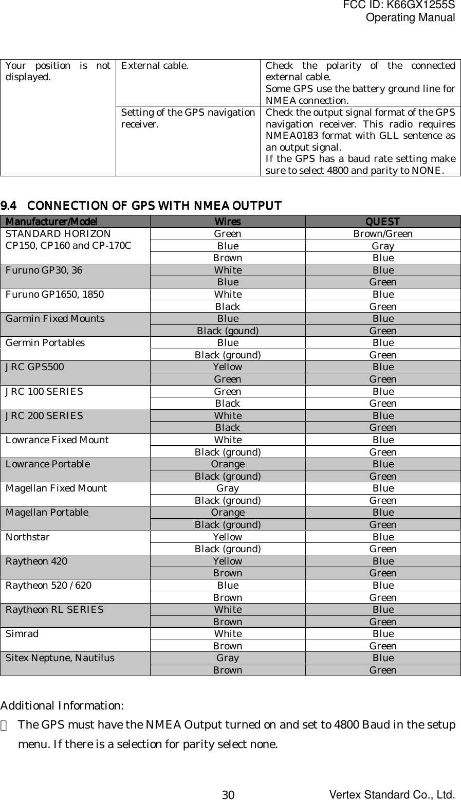
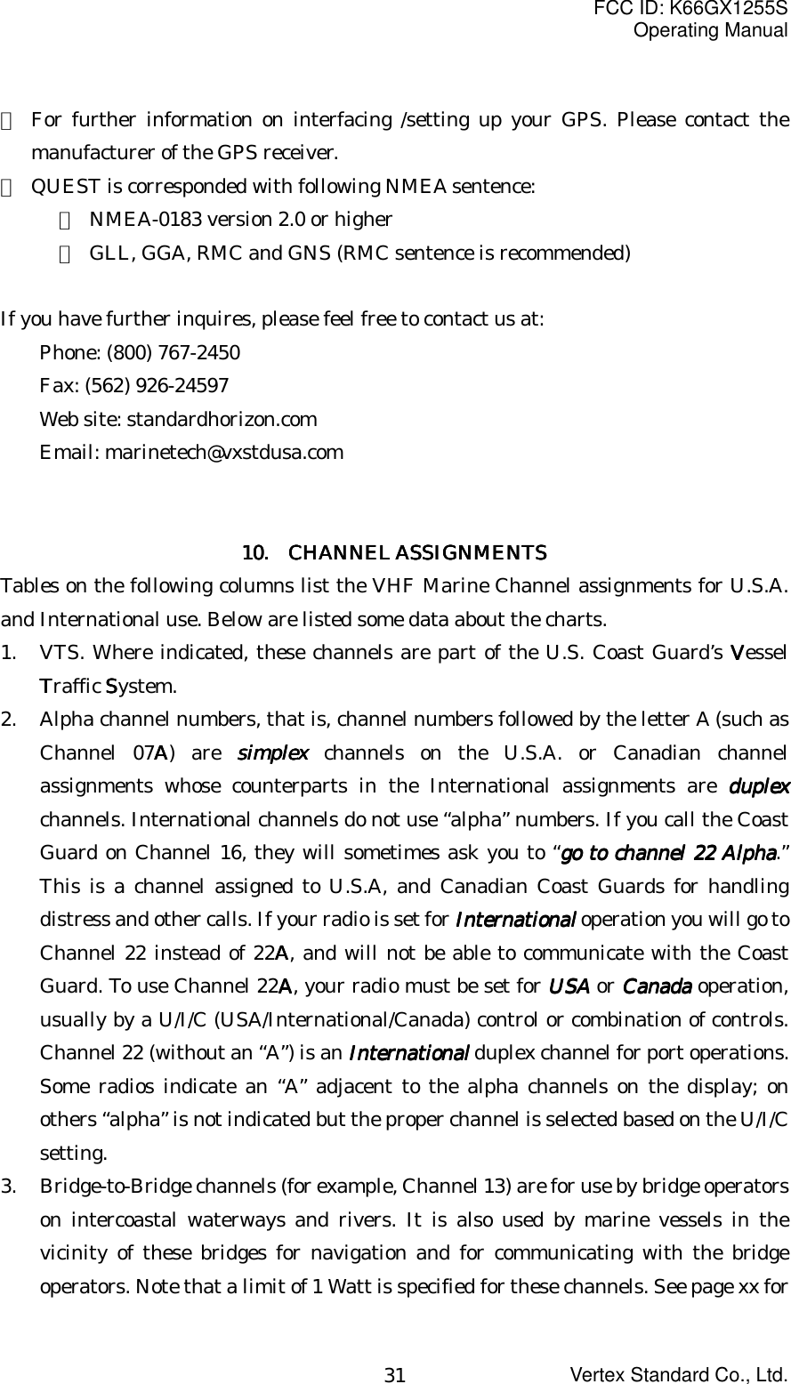
Yaesu Musen GX1255S VHF Marine Transceiver User Manual Operating Manual

Yaesu Musen Co., Ltd. VHF Marine Transceiver Operating Manual

Operating Manual

FCC ID: K66GX1255SOperating ManualVertex Standard Co., Ltd.1Quest GX1255SQuest GX1255SQuest GX1255SQuest GX1255S25 Watt VHF/FM Marine Transceiver 25 Watt VHF/FM Marine Transceiver 25 Watt VHF/FM Marine Transceiver 25 Watt VHF/FM Marine Transceiver Owner's ManualOwner's ManualOwner's ManualOwner's Manual・  One-Button DSC Distress Call Automatically Sends Latitude & Longitude andVessel ID・  Programmable Scan & Priority Ch16 Scan・  NOAA Weather Alert・  Backlit LCD & Keys・  Huge LCDTABLE OF CONTENTSTABLE OF CONTENTSTABLE OF CONTENTSTABLE OF CONTENTSFCC RADIO LICENSE INFORMATIONSTATION LICENSERADIO CALL SIGNCANADIAN SHIP STATION LICENSINGFCC NOTICE1  GENERAL INFORMATION1.1  INTRODUCTION1.2  FCC/INDUSTRY CANADA INFORMATION2  ACCESSORIES2.1  PACKING LIST2.2  OPTIONS3  CONTROLS AND INDICATORS3.1  CONTROLS AND CONNECTIONS4  INSTALLATION4.1  LOCATION4.2  ELECTRICAL CONNECTIONS4.3  ACCESSORY CABLE4.4  OPTIONAL CMB16 FLUSH MOUNT INSTALLATION5  BASIC OPERATION5.1  RECEPTION5.2  TRANSMISSION5.3    TRANSMIT TIME - OUT TIMER (TOT)5.4  SIMPLEX/DUPLEX CHANNEL USE5.5    USA, CANADA, AND INTERNATIONAL MODE5.6  NOAA WEATHER CHANNELS5.7  NOAA WEATHER ALERT
FCC ID: K66GX1255SOperating ManualVertex Standard Co., Ltd.25.8  MEMORY SCANNING (M-SCAN)5.9  PRIORITY SCANNING (P-SCAN)5.10  POSITION INDICATION5.11    RESETTING THE TRANSCEIVER’S MICROPROCESSOR6  DIGITAL SELECTIVE CALLING6.1  GENERAL6.1.1    Digital Selective Calling (DSC)6.1.2    Maritime Mobile Service Identity (MMSI)6.2  SENDING A DISTRESS CALL6.3  SENDING AN INDIVIDUAL CALL6.4  SENDING AN ALL SHIPS CALL6.5  RECEIVING DSC CALLS6.5.1    Receiving a distress call6.5.2    Receiving a distress relay call6.5.3    Receiving an all ships call6.5.4    Receiving a geographical area call6.5.5    Receiving an individual call7.    DSC / RADIO SETUP MODE7.1  SETUP7.2  LAMP ADJUSTING7.3  LCD CONTRAST7.4  CH NAMING7.5    INDIVIDUAL DIRECTORY SETUP (DSC)7.6    KEY BEEP (ON OR OFF)7.7  INDIVIDUAL RING7.8  TIME OFFSET7.9  USER MMSI INPUT7.10    DSC SCANNING TO CHANGE DSC SCAN METHOD8  OPERATING PRACTICES8.1  EMERGENCY (CHANNEL 16 USE)8.2    CALLING ANOTHER VESSEL (CHANNEL 16 OR 9)8.3  MAKING TELEPHONE CALLS8.4    OPERATING ON CHANNELS 13 AND 678.5  PROHIBITED COMMUNICATIONS8.6  NOAA WEATHER ALERT TESTING8.7  DIGITAL SELECTIVE CALLING (DSC)
FCC ID: K66GX1255SOperating ManualVertex Standard Co., Ltd.38.7.1  USCG DSC Watch8.8    MARITIME MOBILE SERVICE IDENTITY (MMSI)8.8.1    What is a MMSI?8.9    USING DIGITAL SELECTIVE CALLING FEATURES8.9.1  Distress Call8.9.2  Individual Call8.9.3  Urgency Call8.9.4  Safety Call8.10   ADDITIONAL DIGITAL SELECTIVE CALLING INFORMATION8.11  ABOUT VHF RADIO8.12    SELECTING AN ANTENNA8.13  COAXIAL CABLE9  MAINTENANCE9.1  REPLACEMENT PARTS9.2  FACTORY SERVICE9.3  TROUBLESHOOTING CHART10.  CHANNEL ASSIGNMENTS11.  WARRANTY12.  SPECIFICATIONS12.1  GENERAL12.2  TRANSMITTER12.3  RECEIVERSafety / Warning InformationSafety / Warning InformationSafety / Warning InformationSafety / Warning InformationWARNINGWARNINGWARNINGWARNING - DO NOT operate the GX-1255S radio when someone (bystanders) outsidethe vehicle is within following range.Safety Safety Safety Safety Training information:Training information:Training information:Training information:Antennas used for this transmitter must not exceed an antenna gain of 0 dB.    Theradio must be used in vessel-mount configurations with a maximum operating dutyfactor not exceeding 50%, in typical Push-to-Talk configurations.This radio is restricted to occupational use, work related operations only where theradio operator must have the knowledge to control the exposure conditions of itspassengers and bystanders by maintaining the minimum separation distance of 0.71 m(2.33 feet).Failure to observe these restrictions will result in exceeding the FCC RF exposure
FCC ID: K66GX1255SOperating ManualVertex Standard Co., Ltd.4limits.Antenna Installation:Antenna Installation:Antenna Installation:Antenna Installation:The antenna must be located at least 0.71 m (2.33 feet) away from passengers in orderto comply with the FCC RF exposure requirements.For roof top installation, the antenna must be placed in the center of the roof.ON-LINE WARRANTY REGISTRATIONON-LINE WARRANTY REGISTRATIONON-LINE WARRANTY REGISTRATIONON-LINE WARRANTY REGISTRATIONPlease visit www.standardhorizon.com to register the QUEST Marine VHF. It should benoted that visiting the Web site from time to time may be beneficial to you, as newproducts are released they will appear on the STANDARD HORIZON Web site.PRODUCT SUPPORT INQUIRIESPRODUCT SUPPORT INQUIRIESPRODUCT SUPPORT INQUIRIESPRODUCT SUPPORT INQUIRIESIf you have any questions or comments regarding the use of the QUEST, you can visitthe STANDARD HORIZON Web site to send an E-Mail or contact the Product Supportteam at 562/404-2700 M-F 7:00-5:00PST.FCC RADIO LICENSE INFORMATIONFCC RADIO LICENSE INFORMATIONFCC RADIO LICENSE INFORMATIONFCC RADIO LICENSE INFORMATIONStandard Horizon radios comply with the Federal Communication Commission (FCC)requirements that regulate the Maritime Radio Service.STATION LICENSESTATION LICENSESTATION LICENSESTATION LICENSEAn FCC ship station license is no longer required for any vessel traveling in U.S. waterswhich uses a VHF marine radio, RADAR or EPIRB, and which is not required to carryradio equipment. However, any vessel required to carry a marine radio on aninternational voyage, carrying a HF single side band radiotelephone or marine satelliteterminal. FCC license forms, including applications for ship (506) and land stationlicenses can be downloaded via the Internet at www.fcc.gov/forms. To obtain a form fromthe FCC, call (888) 225-5322.RADIO CALL SIGNRADIO CALL SIGNRADIO CALL SIGNRADIO CALL SIGNCurrently the FCC does not require recreational boaters to have a Ship Radio StationLicense. The USCG recommends the boats registration number and the state to beused.
FCC ID: K66GX1255SOperating ManualVertex Standard Co., Ltd.5CANADIAN SHIP STATION LICENSINGCANADIAN SHIP STATION LICENSINGCANADIAN SHIP STATION LICENSINGCANADIAN SHIP STATION LICENSINGYou may need a license when traveling in Canada.. If you do need a license contact theirnearest field office or regional office or write:Industry CanadaIndustry CanadaIndustry CanadaIndustry CanadaRadio Regulatory BranchRadio Regulatory BranchRadio Regulatory BranchRadio Regulatory BranchAttn: DOSPAttn: DOSPAttn: DOSPAttn: DOSP300 Slater Street300 Slater Street300 Slater Street300 Slater StreetOttawa, OntarioOttawa, OntarioOttawa, OntarioOttawa, OntarioCanada, KIA 0C8Canada, KIA 0C8Canada, KIA 0C8Canada, KIA 0C8FCC NOTICEFCC NOTICEFCC NOTICEFCC NOTICENOTICENOTICENOTICENOTICEUnauthorized changes or modifications to this equipment may void compliance withFCC Rules. Any change or modification must be approved in writing by STANDARDHORIZON.NOTICENOTICENOTICENOTICEThis equipment has been tested and found to comply with the limits for a Class B digitaldevice, pursuant to Part 15 of the FCC Rules. These limits are designed to providereasonable protection against harmful interference in a residential installation. Thisequipment generates, uses and can radiate radio frequency energy and, if not installedand used in accordance with the instructions, may cause harmful interference to radiocommunications. However, there is no guarantee that interference will not occur in aparticular installation. If this equipment does cause harmful interference to radio ortelevision reception, which can be determined by turning the equipment off and on, theuser is encouraged to try to correct the interference by one or more of the followingmeasures:- Reorient or relocate the receiving antenna.- Increase the separation between the equipment and receiver.- Connect the equipment into an outlet on a circuit different from that to which thereceiver is connected.- Consult the dealer or an experienced radio/TV technician for help.
FCC ID: K66GX1255SOperating ManualVertex Standard Co., Ltd.61 1 1 1     GENERAL INFORMATIONGENERAL INFORMATIONGENERAL INFORMATIONGENERAL INFORMATION1.1 1.1 1.1 1.1     INTRODUCTIONINTRODUCTIONINTRODUCTIONINTRODUCTIONThe STANDARD HORIZON GX1255S is a VHF/FM transceiver designed for use in thefrequency range of 156.025 to 163.275 MHz. The GX1255S requires 13.8V for operationand has a switchable RF output power of 1 watt or 25 watts.The transceiver is capable of RTCM SC101 DSC (Digital Selective Calling) operation.The transceiver operates on all currently-allocated marine channels which areswitchable for use with either USA, International, or Canadian regulations. It has anemergency channel 16 which can be immediately selected from any channel by pressingthe red 16/9 key. NOAA Weather channels can also be accessed immediately by pressingthe WX key.Other features of the transceiver include: scanning, priority scanning, submersible mic,high and low voltage warning, and GPS repeatability.1.2 1.2 1.2 1.2      FCC/ INDUSTRY CANADA INFORMATIONFCC/ INDUSTRY CANADA INFORMATIONFCC/ INDUSTRY CANADA INFORMATIONFCC/ INDUSTRY CANADA INFORMATIONThe following data pertaining to the transceiver is necessary to fill out thelicense application.Type Acceptance ……………………………….…………………………….. FCC Part 80Output Power ………………………………………….. 1 Watt (low) and 25 Watts (high)Emission ……………………………………………………………….16K0G3E, 16K0G2BFrequency Range ……………………………………………….. 156.025 to 163.275 MHzFCC Type Number …………………………………………………………… K66GX1255SIndustry Canada Type Approval ……………………………………………… PENDING2222     ACCESSORIES ACCESSORIES ACCESSORIES ACCESSORIES2.1 2.1 2.1 2.1     PACKING LISTPACKING LISTPACKING LISTPACKING LISTWhen the package containing the transceiver is first opened, please check it for thefollowing contents:・  GX1255S QUEST Transceiver (with White/Black Microphone)・  Mounting Bracket (with attaching hardware and hanger kit)・  Owner’s Manual・  Quick-Reference Card
FCC ID: K66GX1255SOperating ManualVertex Standard Co., Ltd.7・  Power Cord・  Dust Cover2.2 2.2 2.2 2.2     OPTIONSOPTIONSOPTIONSOPTIONSCMB16 …………………………………………………………………. Flush-Mount Bracket101S ………………………………………………………………….. Mini Extension Speaker201S ………………………………………………………………………… Extension Speaker201SZ ……………………………………………………… Flush Mount Extension Speaker201SBK …………………………………………………………….. Black Extension Speaker201SBKZ ………………………………………….. Flush Mount Black Extension Speaker3333     CONTROLS AND INDICATORS CONTROLS AND INDICATORS CONTROLS AND INDICATORS CONTROLS AND INDICATORSNOTENOTENOTENOTEThis section defines each control of the transceiver. See Figure 1 for location of controls.For detailed operating instructions refer to chapter 4 of this manual.3.1 3.1 3.1 3.1     CONTROLS AND CONNECTIONSCONTROLS AND CONNECTIONSCONTROLS AND CONNECTIONSCONTROLS AND CONNECTIONS(1) POWER SWITCH/VOLUME CONTROLTurns the transceiver on and off as well as adjusts the audio volume.Turn this control clockwise to turn the radio on and to increase the volume.Counterclockwise rotation into the click-stop will turn the radio off.Secondary UseWhen the transceiver is turned on while the SCAN and WX keys are held down, theinternal microprocessor is reset. This clears the memory and all user-programmedsettings, such as scan memory. This condition is known as the default condition, thesame as when shipped from the factory. For a list of these defaults, see the sectionon Resetting the Transceiver’s Microprocessor.NOTEResetting the microprocessor will not erase DSC MMSI and Directory Callinformation.(2) SQUELCH CONTROL (SQL)Sets the point at which random noise on the channel does not activate the audiocircuits but a received signal does. This point is called the squelch threshold.Further adjustment of the squelch control will degrade reception of wanted
FCC ID: K66GX1255SOperating ManualVertex Standard Co., Ltd.8transmissions.(3) KEY PAD16/9 KeyImmediately recalls channel 16 from any channel location. Holding down this keyrecalls channel 9. Pressing the 16/9 key again reverts to the previous selectedworking channel.Secondary usePlease see secondary use for the WX key.WX KeyImmediately recalls the previously selected NOAA weather channel from anychannel location.Secondary use1. Holding down the 16/9 key while pressing the WX key changes the mode fromUSA to International or Canadian.2. Holding down the WX and SCAN key while turning the power on resets themicroprocessor and erases scan channels from memory. This clears the memoryand establishes the factory-set defaults. For a list of these defaults, see thesection on Resetting the Transceiver’s Microprocessor.DW KeyWatches for a transmission on CH16 and another selected channel until eithersignal is received. (Duel watch)NOTENOTENOTENOTE: When enable the DCS SCANNING feature (see section 7.7 DCSSCANNING), watches for a transmission on CH16, another selectedchannel, and CH70CH70CH70CH70 until either signal is received (Triple watch).SCAN Key1. Starts and stops scanning of programmed channels.2. If held while the UP or DOWN key on the microphone are pressed or UP orDOWN key on radio are pressed, the radio will show the channels in scanmemory. This function will not work if the unit is scanning.NOTE: The priority channel is channel 16 only.DISTRESS Key
FCC ID: K66GX1255SOperating ManualVertex Standard Co., Ltd.9Used to send a DSC Distress Call. To send the distress call see section 6.2 (Sendinga Distress Call).UP and DOWN KeysThe UP and DOWN keys are used to select a desired channel and to select items inthe DSC OPERATION and SETUP menus. The UP or DOWN key on themicrophone can also be used to select channels.CALL/SET KeyThe CALL/SET key functions as the enter key.Secondary usePress the CALL/SET key to access the DSC OPERATION menu. The INDIVIDUALand ALL SHIPS CALLS functions can be accessed from the DSC OPERATIONmenu.Press and hold the CALL/SET key to access the SETUP menu. The followingfunctions can be accessed in the SETUP menu; LAMP ADJUST, KEY BEEP, WA,INDIV DIR, INDIV RING, TIME SET, USER MMSI, and DSC SCAN.H/L KeyToggles between high and low power. When the H/L key is pressed while thetransceiver is on channel 13 or 67, the power will temporarily switch from LO to HIpower until the PTT is released. The H/L key does not function on transmitinhibited and low power only channels.Secondary usePress the H/L key to display the Position Data on the LCD, when connected the GPSreceiver.(4) ACCESSORY CONNECTION CABLEConnects the radio to a GPS, and an external speaker.(5) DC INPUT CABLEConnects the radio to a DC power supply of 13.8V(6) ANTENNA JACKConnects an antenna to the transceiver. Use a marine VHF antenna with an
FCC ID: K66GX1255SOperating ManualVertex Standard Co., Ltd.10impedance of 50 ohms.(7) PTT (Push-To-Talk) SWITCHKeys the transmitter when the transceiver is in radio mode. If the transceiver is inthe intercom operation mode, it activates the microphone for the intercom.(8) MICROPHONETransmits the voice message with reduction of background noise.(9) UP(!) and DOWN(") KEYSThe UP(!) and DOWN(") on the microphone function the same as the UP andDOWN key on the front panel of the transceiver.(10) 16/9 KeyPressing the 16/9 key Immediately recalls channel 16 from any location. Press andhold the 16/9 key to recall channel 9. Pressing the 16/9 key again revert the radio tothe previous select channel.4 4 4 4     INSTALLATIONINSTALLATIONINSTALLATIONINSTALLATION4.1 4.1 4.1 4.1  LOCATIONLOCATIONLOCATIONLOCATIONThe radio can be mounted at any angle. Choose a mounting location that:・  is far enough from any compass to avoid any deviation in compass reading due tothe speaker magnet・  provides accessibility to the front panel controls・  allows connection to a power source and an antenna・  has nearby space for installation of a microphone hanger・  the antenna must be mounted at least 3 feet from radio4.2 4.2 4.2 4.2     ELECTRICAL CONNECTIONSELECTRICAL CONNECTIONSELECTRICAL CONNECTIONSELECTRICAL CONNECTIONSCAUTIONCAUTIONCAUTIONCAUTION: Reverse polarity connections will damage the radio!Connect the power cord and antenna to the radio. Antenna and Power Supplyconnections are as follows (see Figure 2):1. Mount the antenna at least 3 feet away from the radio. At the rear of the radio,connect the antenna cable. It must have a PL259 connector. RG-8/U coaxial cable
FCC ID: K66GX1255SOperating ManualVertex Standard Co., Ltd.11must be used if the antenna is 25 feet or more from the radio. RG58 cable can beused for distances less than 25 feet.2. Connect the red power wire to a 13.8 VDC ±20% power source. Connect the blackpower wire to a negative ground.3. If an optional remote extension speaker is to be used, refer to section 4.3 forconnections.4. It is advisable to have a Certified Marine Technician check the power output andthe standing wave ratio of the antenna after installation.4.3 4.3 4.3 4.3     ACCESSORY CABLEACCESSORY CABLEACCESSORY CABLEACCESSORY CABLEWhite: External speaker (+)Yellow: External speaker (–)Blue: NMEA IN (+) from GPS navigation receiverGreen: NMEA IN (–) from GPS navigation receiverWhen connecting the external speaker or GPS navigation receiver, strip off about 1 inch(2.5 cm) of the specified wire’s insulation.NOTENOTENOTENOTE: Never short wires. This may lead to malfunctions.4.4 4.4 4.4 4.4      OPTIONAL CMB16 FLUSH MOUNT INSTALLATIONOPTIONAL CMB16 FLUSH MOUNT INSTALLATIONOPTIONAL CMB16 FLUSH MOUNT INSTALLATIONOPTIONAL CMB16 FLUSH MOUNT INSTALLATION1. Make a rectangular template for the flush mount measuring 2” H x 5-5/8” W.2. Use the template to mark the location where the rectangular hole is to be cut.Confirm the space behind the dash or panel is deep enough to accommodate thetransceiver (at least 6 inches deep).There should be at least 1/2 inch between the transceiver’s heatsink and any wiring,cables or structures.3. Cut out the rectangular hole and insert the transceiver.4. Fasten the brackets to the sides of the transceiver with the lock washer nutcombination, so that the mounting screw base faces the mounting surface (seeFigure 3).5. Turn the adjusting screw to adjust the tension so that the transceiver is tightagainst the mounting surface.
FCC ID: K66GX1255SOperating ManualVertex Standard Co., Ltd.125555     BASIC OPERATION BASIC OPERATION BASIC OPERATION BASIC OPERATION5.1 5.1 5.1 5.1     RECEPTIONRECEPTIONRECEPTIONRECEPTION1. After the transceiver has been installed, ensure that the power supply and antennaare properly connected.2. Turn the VOL/PWR knob clockwise to turn on the radio.3. Turn the SQL knob fully counterclockwise. This state is known as “squelch off”.4. Turn up the VOL/PWR knob until noise or audio from the speaker is at acomfortable level.5. Turn the SQL knob clockwise until the random noise disappears. This state isknown as the “squelch threshold.”6. Press the UP or DOWN key to select the desired channel. Refer to the channel charton page xx for available channels.7. When a message is received, adjust the volume to the desired listening level. The“BUSY” indicator in the LCD is displayed indicating that the channel is being used.5.2 5.2 5.2 5.2     TRANSMISSIONTRANSMISSIONTRANSMISSIONTRANSMISSION1. Perform steps 1 through 6 of RECEPTION.2. Before transmitting, monitor the channel to ensure it is clear. THIS IS A FCCREQUIREMENT!3. Press the PTT (push-to-talk) switch. The TX indicator on the LCD is displayed.4. Speak slowly and clearly into the microphone.5. When the transmission is finished, release the PTT switch.NOTENOTENOTENOTE: This is a noise-canceling microphone. The oval slot on the top of microphoneshould be positioned within 1 inch (2.5 cm) from the mouth for optimumperformance.6. Refer to page xx for standard transceiver operating procedures.5.35.35.35.3       TRANSMIT TIME - OUT TIMER (TOT)  TRANSMIT TIME - OUT TIMER (TOT)  TRANSMIT TIME - OUT TIMER (TOT)  TRANSMIT TIME - OUT TIMER (TOT)When the PTT switch on the microphone is held down, transmit time is limited to 5minutes. This prevents unintentional transmissions. About 10 seconds before automatictransmitter shutdown, a warning beep will be heard from the speaker(s). Thetransceiver will automatically go to receive mode, even if the PTT switch is continuallyheld down. Before transmitting again, the PTT switch must first be released and thenpressed again.
FCC ID: K66GX1255SOperating ManualVertex Standard Co., Ltd.135.45.45.45.4     SIMPLEX/DUPLEX CHANNEL USE SIMPLEX/DUPLEX CHANNEL USE SIMPLEX/DUPLEX CHANNEL USE SIMPLEX/DUPLEX CHANNEL USERefer to the VHF MARINE CHANNEL CHART (page xx) for instructions on use ofsimplex and duplex channels.NOTENOTENOTENOTE: All channels are factory-programmed in accordance with FCC (USA), IndustryCanada (Canada), and International regulations. Mode of operation cannot be alteredfrom simplex to duplex or vice-versa.5.5 5.5 5.5 5.5      USA, CANADA, AND INTERNATIONAL MODEUSA, CANADA, AND INTERNATIONAL MODEUSA, CANADA, AND INTERNATIONAL MODEUSA, CANADA, AND INTERNATIONAL MODE1. To change the modes, hold the 16/9 key and press the WX key. The mode changesfrom USA to International to Canadian with each press of the WX key.2. USA will be displayed on the LCD for USA mode, INTL will be displayed forInternational mode, and CAN will be displayed for Canadian mode.3. Refer to the VHF MARINE CHANNEL CHART (page xx) for allocated channels ineach mode.5.6 5.6 5.6 5.6     NOAA WEATHER CHANNELSNOAA WEATHER CHANNELSNOAA WEATHER CHANNELSNOAA WEATHER CHANNELS1. To receive a NOAA weather channel, press the WX key from any channel. Thetransceiver will go to the last selected weather channel.2. Press the UP or DOWN key on the microphone to select a different NOAA weatherchannel.3. To exit from the NOAA weather channels, press the WX key. The transceiverreturns to the channel it was on prior to a weather channel.5.7 5.7 5.7 5.7     NOAA WEATHER ALERTNOAA WEATHER ALERTNOAA WEATHER ALERTNOAA WEATHER ALERTIn the event of extreme weather disturbances, such as storms and hurricanes, theNOAA (National Oceanic and Atmospheric Administration) sends a weather alertaccompanied by a 1050 Hz tone and subsequent weather report on one of the NOAAweather channels. The transceiver is capable of receiving this alert if the following isperformed:1. Program NOAA weather channels into the transceiver’s memory for scanning.Follow the same procedure as for regular channels under Section 5.8.2. Press the SCAN key once to start memory scanning or hold down the SCAN keyduring memory scanning to start priority scanning.3. The programmed NOAA weather channels will be scanned along with the regular-programmed channels. However, scanning will not stop on a normal weatherbroadcast unless a NOAA alert is received.
FCC ID: K66GX1255SOperating ManualVertex Standard Co., Ltd.144. When an alert is received on a NOAA weather channel, scanning will stop and thetransceiver will emit a loud beep to alert the user of a NOAA broadcast.5. Press the WX key to stop the alert tone and receive the weather report.NOTENOTENOTENOTE: If the WX key is not pressed the alert tone will be emitted for 5 minutes andthen the weather report will be received.5.85.85.85.8       MEMORY SCANNING (M-SCAN)  MEMORY SCANNING (M-SCAN)  MEMORY SCANNING (M-SCAN)  MEMORY SCANNING (M-SCAN)NOTENOTENOTENOTE・  During scanning, the dot matrix area of the LCD will show M-SCAN or P-SCANdepending on the scan mode selected.・  If position is displayed this icon will be hidden.1. Adjust the SQL knob until background noise disappears.2. Select a desired channel to be scanned using the UP or DOWN key.Press and hold the SCAN key, MEM will appear on the LCD which indicates thechannel has been programmed into the transceivers memory.3. Repeat step 2 for all the desired channels to be scanned.4. To DELETE a channel from the transceiver’s memory, press and hold the SCAN key,MEM will disappear in the LCD.5. To start scanning, press the SCAN key. Scanning will proceed from the lowest to thehighest programmed channel number and will stop on a channel when atransmission is received.6. The channel number will blink during reception.7. To stop scanning, press the SCAN, 16/9, WX, or PTT key.5.9 5.9 5.9 5.9      PRIORITY SCANNING (P-SCAN)PRIORITY SCANNING (P-SCAN)PRIORITY SCANNING (P-SCAN)PRIORITY SCANNING (P-SCAN)1. The priority channel is set to channel 16.2. For priority scanning during M-SCAN, press and hold the SCAN key, until P-SCANappears in the LCD. Scanning will proceed between the memorized channels andthe priority channel. The priority channel will be scanned after each programmedchannel.3. The scanning will be performed while receiving the MEM CH (memorized channel).4. To stop scanning, press the SCAN, 16/9, WX, or PTT key.NOTENOTENOTENOTE:Triple watch (T/W) means the radio is watching CH70 for DSC Calls.Dual watch (D/W) means the radio is not watching CH70 for DSC Calls.
FCC ID: K66GX1255SOperating ManualVertex Standard Co., Ltd.155.10 5.10 5.10 5.10  POSITION POSITION POSITION POSITION INDICATION INDICATION INDICATION INDICATIONThe transceiver has the ability to display the vessel’s position (LAT/LON) forConfirmation the data, if connected to a GPS receiver.1. Displays position information, during press and hold the H/L keyIf the GPS receiver receives no signal, the display will be as shown in theillustration.2. To hide the position information, release the H/L key.5.11  TIME5.11  TIME5.11  TIME5.11  TIME INDICATION INDICATION INDICATION INDICATIONThe transceiver has the ability to display the TIME on the upper side, if connected to aGPS receiver.NOTENOTENOTENOTE: The TIME OFFSET should be set to local time in the DSC/RADIO setup modewhen the radio is connected the GPS navigation receiver. To adjust TIME OFFSET toyour local time, refer to section 7.11 TIME OFFSET.5.15.15.15.11111         RESETTING THE TRANSCEIVERRESETTING THE TRANSCEIVERRESETTING THE TRANSCEIVERRESETTING THE TRANSCEIVER’’’’S MICROPROCESSORS MICROPROCESSORS MICROPROCESSORS MICROPROCESSORResetting the microprocessor restores the initial, factory supplied conditions in thetransceiver. These are called the default conditions.To reset the microprocessor, first turn the transceiver off. Then while pressing the WXand SCAN keys, turn the transceiver on. The default conditions are:・  No channels in SCAN memory.・  Channel 16 will be selected when the transceiver is turned on.・  WX channel 01 will be recalled when the WX key is pressed.・  Key beep will be on.NOTENOTENOTENOTE: Resetting the microprocessor will not erase DSC MMSI and Directoryinformation.6 6 6 6     DIGITAL SELECTIVE CALLINGDIGITAL SELECTIVE CALLINGDIGITAL SELECTIVE CALLINGDIGITAL SELECTIVE CALLING6.1 6.1 6.1 6.1     GENERALGENERALGENERALGENERAL6.1.1    Digital Selective Calling (DSC)Digital Selective Calling is a semi-automated method of establishing a radio call, it hasbeen designated by the International Maritime Organization (IMO) as an internationalstandard for establishing VHF, MF and HF radio calls. It had also been designated aspart of the Global Maritime Distress and Safety System (GMDSS). It is planned that
FCC ID: K66GX1255SOperating ManualVertex Standard Co., Ltd.16DSC will eventually replace aural watches on distress frequencies and will be used toannounce routine and urgent maritime safety information broadcasts.This new system will allow mariners to instantly send a distress call with GPS position(when connected to the transceiver) to the US Coast Guard and other vessels withinrange of the transmission. DSC will also allow mariners to initiate or receive distress,urgency, safety routine, POS Request, POS Send and Group calls to or from anothervessel equipped with a DSC transceiver.6.1.2    Maritime Mobile Service Identity (MMSI)What is an MMSI?What is an MMSI?What is an MMSI?What is an MMSI?An MMSI is a nine digit number used on Marine Transceiver capable of using DigitalSelective Calling (DSC). This number is used like a telephone number to selectively callother vessels. Refer to section 7.9 (USER MMSI INPUT).How can I obtain a MMSI assignment?How can I obtain a MMSI assignment?How can I obtain a MMSI assignment?How can I obtain a MMSI assignment?Contact your dealer or Standard Horizon for details.WARNINGWARNINGWARNINGWARNING: This radio is designed to generate a digital maritime distress and safetycall to facilitate search and rescue. To be effective as a safety device, this equipmentmust be used only within communication range of a shore-based VHF marine channel70 distress and safety watch system. The range of signal may vary but under normalconditions should be approximately 20 nautical miles.6.2 6.2 6.2 6.2     SENDING A DISTRESS CALLSENDING A DISTRESS CALLSENDING A DISTRESS CALLSENDING A DISTRESS CALLThe distress call automatically includes the vessel’s DSC MMSI and Lat/Lon position.Refer to section 7.9 (USER MMSI INPUT). The vessel’s position can be sent only if thetransceiver is properly connected to an operating GPS receiver.1. Lift the red spring loaded DISTRESS cover and press the DISTRESS key. The“DISTRESS” icon will appear on the LCD.2. Press and hold the DISTRESS key for 3 seconds or more. Count down the holdingtime on the LCD.3. When the distress signal is sent, “TX” icon will appear on the LCD. After themessage has been sent, the Distress Alarm will sound.4. The transceiver “shadow-watches” for a transmission between CH16 and CH70until an acknowledgment signal is received. “RECEIVED ACK” will scroll on theLCD.
FCC ID: K66GX1255SOperating ManualVertex Standard Co., Ltd.175. If no acknowledgment is received, the distress call is repeated in 3.4 to 4.5 minuteintervals until an acknowledgment is received.6. To cancel a Distress Call, pressing the UP or DOWN key until the “CANCEL” iconappear. Then, press the CALL/SET key or turn off the radio.7. When a distress acknowledgment is received, a distress alarm sounds and channel16 is automatically selected.8. To cancel the alarm, press any key.NOTENOTENOTENOTE: When a GPS receiver with NMEA output is connected, the vessel’s position isautomatically transmitted with the distress call.6.36.36.36.3       SENDING AN INDIVIDUAL CALL  SENDING AN INDIVIDUAL CALL  SENDING AN INDIVIDUAL CALL  SENDING AN INDIVIDUAL CALLThis feature allows the user to contact another user vessel DSC and to automaticallyswitch the receiving DSC radio to a desired working channel. This feature is similar tocalling a vessel on CH16 and requesting to go to a another channel. To send anindividual call, see section 7.5 (INDIVIDUAL DIRECTORY SETUP). The individual callfunction allows you to transmit a DSC signal to a specific party only, promptingcommunication on a voice channel.1. Select the traffic channel for voice communication.2. Press the CALL/SET key. The “INDIVIDUAL” icon will appear on the LCD.3. Press the CALL/SET key again. The individual address will appear.4. Press the UP or DOWN key to select the individual you want to contact.5. Press the CALL/SET key to transmit the individual DSC signal.6. After INDIVIDUAL CALL is transmitted, the transceiver will wait 8 seconds forthe acknowledgment. If the reply signal is not received, the transceiver willtransmit again.7. After the second INDIVIDUAL CALL is transmitted, if the reply signal is notreceived, “NO REPL” icon will appear on the LCD to prompt the user to send thecall again or exit the mode.8. When an individual call acknowledgment “able to comply” is received, theestablished channel is automatically selected and an alarm sounds.9. When an individual call acknowledgment with “unable to comply” is received, theestablished channel is automatically selected.10. To cancel, pressing the UP or DOWN key until the “EXIT” icon appear. Then pressthe CALL/SET key.This procedure can be also canceled as follows;Press the WX or 16/9 key.
FCC ID: K66GX1255SOperating ManualVertex Standard Co., Ltd.186.4 6.4 6.4 6.4      SENDING AN ALL SHIPS CALLSENDING AN ALL SHIPS CALLSENDING AN ALL SHIPS CALLSENDING AN ALL SHIPS CALLThe All Ships Call function allows contact to be established with other vessel stationswithout having their ID in the individual calling directory.Also, priority for the call can be designated as Urgency, Safety or Routine.URGENCY Call:  This type of call is used when a vessel may not truly be in distress,but have a potential problem that may lead to a distress situation.SAFETY Call:  Used to transmit boating safety information to other vessels.This message usually contains information about an overdue boat, debris in the water.Loss of a navigation aid or an important meteorological message.1. Select the traffic channel (for voice communication).2. Press the CALL/SET key. The “INDIVID” icon will appear on the LCD.3. Press the DOWN key to select the “ALL SHIP.”4. Press the CALL/SET key again.5. Press the UP or DOWN key to select the nature of call (“URGENCY,” “SAFETY” or“ROUTINE”).6. Press the CALL/SET key to transmit the selected type of ALL SHIPS DSC call.When “ROUTINE” is selected, the signal is transmitted then the transceiver willwait on the channel selected in step 1.7. After the ALL SHIPS CALL is transmitted, the transceiver will wait on CH16except ROUTINE.6.6.6.6.5 5 5 5  RECEIVING DSC CALLS RECEIVING DSC CALLS RECEIVING DSC CALLS RECEIVING DSC CALLSSeveral types of DSC transmissions can be received. The required action depends on theparticular DSC type as outlined in the following examples.NOTE: If the radio is receiving on a working channel or transmitting on aworking channel, DSC calls will not be received.6.5.1    Receiving a distress call1. A distress call is received. An emergency alarm sounds.Then channel 16 is automatically selected.2. Press any key to stop the alarm.3. Press the UP or DOWN key to select the receiving distress data:
FCC ID: K66GX1255SOperating ManualVertex Standard Co., Ltd.19・  RECEIVED DISTRESS・  MMSI・  TIME (UTC)・  Latitude・  LongitudeNOTENOTENOTENOTE: If the received distress data does not include the position data, “NOPOSITION DATA” will scroll on the LCD.NOTENOTENOTENOTE: You must continue monitoring channel 16 as a coast station may requireassistance in any rescue attempt.6.5.2    Receiving a distress relay call1. A distress relay call is received. An emergency alarm sounds.Then channel 16 is automatically selected.2. Press any key to stop the alarm.NOTENOTENOTENOTE: You must continue monitoring channel 16 as a coast station may requireassistance in any rescue attempt.6.5.3    Receiving an all ships call1. An all ships call is received. An emergency alarm sounds.Then channel 16 is automatically selected.2. Press any key to stop the alarm.3. Monitor channel 16 or traffic channel until the URGENCY communication iscompleted.6.5.4    Receiving a geographical area call1. A geographical call is received. An emergency alarm sounds (different fromDISTRESS). Then the requested channel from the other ship is automaticallyselected.2. Press any key to stop the alarm.3. Monitor the traffic channel for an announcement from the calling ship.NOTENOTENOTENOTE: This feature is only available when a GPS receiver is connected.6.5.5    Receiving an individual callWhen receiving an individual call, an acknowledgment must be sent back to the callingstation.1. An individual call is received. An individual call alarm sounds. Then the radio
FCC ID: K66GX1255SOperating ManualVertex Standard Co., Ltd.20automatically switches to the requested channel.2. Press any key to stop the alarm.3. Press the PTT on the microphone and talk to the calling ship.7.7.7.7.      DSC / RADIO SETUP MODE  DSC / RADIO SETUP MODE  DSC / RADIO SETUP MODE  DSC / RADIO SETUP MODE7.7.7.7.1111        LAMP ADJUSTINGLAMP ADJUSTINGLAMP ADJUSTINGLAMP ADJUSTING1. Press and hold down the CALL/SET key until the “RADIO S” appears.2. Press the CALL/SET key, then press the UP or DOWN key to select “LAMP” item.3. Press the CALL/SET key to enable adjusting this item.4. Press the UP or DOWN key to select the desired level.3: High2: Mid1: Low0: OFF5. Press the CALL/SET key to store the selected level.6. Press the UP or DOWN key to select “EXIT,” then press the CALL/SET key to returnto the normal operation.7.7.7.7.2 2 2 2      KEY BEEP (ON or OFF)KEY BEEP (ON or OFF)KEY BEEP (ON or OFF)KEY BEEP (ON or OFF)1. Press and hold down the CALL/SET key until the “RADIO SETUP” appears.2. Press the CALL/SET key, then press the UP or DOWN key to select “BEEP” item.3. Press the CALL/SET key to enable adjusting this item.4. Press the UP or DOWN key to select “on” or “oF (off).”5. Press the CALL/SET key to store the selected setting.6. Press the UP or DOWN key to select “EXIT,” then press the CALL/SET key to returnto the normal operation.7.7.7.7.3 3 3 3      WEATHER ALERT (ON or OFF)WEATHER ALERT (ON or OFF)WEATHER ALERT (ON or OFF)WEATHER ALERT (ON or OFF)1. Press and hold down the CALL/SET key until the “RADIO SETUP” appears.2. Press the CALL/SET key, then press the UP or DOWN key to select “WX ALT” item.3. Press the CALL/SET key to enable adjusting this item.4. Press the UP or DOWN key to select “on” or “oF (off).”5. Press the CALL/SET key to store the selected setting.6. Press the UP or DOWN key to select “EXIT,” then press the CALL/SET key to returnto the normal operation.
FCC ID: K66GX1255SOperating ManualVertex Standard Co., Ltd.217.4  TIME OFFSET7.4  TIME OFFSET7.4  TIME OFFSET7.4  TIME OFFSETSets the time difference between local time and UTC. Time is displayed, if connectedGPS receiver.1. Press and hold down the CALL/SET key until the “RADIO SETUP” appears.2. Press the CALL/SET key, then press the UP or DOWN key to select “TIME” item.3. Press the CALL/SET key to enable adjusting this item.4. Press the UP or DOWN key to select “Time Offset” form UTC.NOTENOTENOTENOTE: See illustration below to find your offset time from UTC. If 0:00 is assigned,the time is the same as UTC (Universal Time Coordinated or GMT GreenwichMean Time)5. Press the CALL/SET key to store the time offset.6. Press the UP or DOWN key to select “EXIT,” then press the CALL/SET key to returnto the normal operation.7.5    INDIVIDUAL DIRECTORY SETUP (DSC)7.5    INDIVIDUAL DIRECTORY SETUP (DSC)7.5    INDIVIDUAL DIRECTORY SETUP (DSC)7.5    INDIVIDUAL DIRECTORY SETUP (DSC)1. Press and hold down the CALL/SET key until the “RADIO SETUP” appears.2. Press the UP or DOWN key to select “DSC SETUP”.3. Press the CALL/SET key, then press the UP or DOWN key to select “INDIVIDUAL”item.4. Press the CALL/SET key to enable setting this item.5. Press the CALL/SET key again.6. , then press the UP or DOWN key to select “Time Offset” form UTC.7. NOTENOTENOTENOTE: See illustration below to find your offset time from UTC. If 0:00 is assigned,the time is the same as UTC (Universal Time Coordinated) or GMT (GreenwichMean Time)8. Press the CALL/SET key to store the time offset.9. Press the UP or DOWN key to select “EXIT,” then press the CALL/SET key to returnto the normal operation.7.6  INDIVIDUAL RING7.6  INDIVIDUAL RING7.6  INDIVIDUAL RING7.6  INDIVIDUAL RING1. Press and hold down the CALL/SET key until the “RADIO SETUP” appears.2. Press the UP or DOWN key to select “DSC SETUP.”3. Press the CALL/SET key, then press the UP or DOWN key to select “INDIVID”item.
FCC ID: K66GX1255SOperating ManualVertex Standard Co., Ltd.224. Press the CALL/SET key to enable setting this item.5. Press the UP or DOWN key to select ringing time of a INDIVIDUAL CALL.3: 3 minutes continuously2: 15 times1: 10 times0: 5 times6. Press the CALL/SET key to store the selected ringing time.7. Press the UP or DOWN key to select “EXIT,” then press the CALL/SET key to returnto the normal operation.7.7.7.7.7 7 7 7  DSC SCANNING DSC SCANNING DSC SCANNING DSC SCANNINGThe radios software has been updated to improve DSC Channel 70 SCANNING:・  When a DSC call is received the radio will only show Channel 70 on the display ifthe call was directed to the radios MMSI or if it is a Distress or All ships DSC call.・  Selection to turn ON or OFF the DSC SCAN function.When the radio is shipped from the factory it is programmed so CH70 (the DSCchannel) is scanned at all times. A selection has been added to the SETUP MENU in theradio to disable the DSC SCAN. However, turning off DSC SCAN will disable the radiofrom receiving DSC calls i.e.: Individual Call, All Ships Call, Distress Call and PositionRequests. If you want to use any of the functions the selection should be left ON.TO CHANGE DSC SCAN METHOD:1. Press and hold down the CALL/SET key until the “RADIO SETUP” appears.2. Press the UP or DOWN key to select “DSC SET.”3. Press the CALL/SET key, then press the UP or DOWN key to select “DSC SCAN”item.4. Press the CALL/SET key to enable setting this item.5. Press the UP or DOWN key to select “on” or “oF (off).”6. Press the CALL/SET key to store the selected setting.7. Press the UP or DOWN key to select “EXIT,” then press the CALL/SET key to returnto the normal operation.7.8    USER MMSI INPUT7.8    USER MMSI INPUT7.8    USER MMSI INPUT7.8    USER MMSI INPUT1. Press and hold down the CALL/SET key until the “RADIO S” appears.2. Press the UP or DOWN key to select “DCS SET.”
FCC ID: K66GX1255SOperating ManualVertex Standard Co., Ltd.233. Press the CALL/SET key, then press the UP or DOWN key to select “MMSI” item.4. Press the CALL/SET key to enable setting this item.5. Press the UP or DOWN key to select first number of your MMSI, then press theCALL/SET key to define the setting.6. Repeat above step to set your MMSI (up to 9 digits).7. When the last number of your MMSI is in place, press and hold the CALL/SET keyto store your MMSI.8. Press the UP or DOWN key to select “EXIT,” then press the CALL/SET key to returnto the normal operation.8888        OPERATING PRACTICESOPERATING PRACTICESOPERATING PRACTICESOPERATING PRACTICES8888.1 .1 .1 .1      EMERGENCY (CHANNEL 16 USE)EMERGENCY (CHANNEL 16 USE)EMERGENCY (CHANNEL 16 USE)EMERGENCY (CHANNEL 16 USE)Channel 16 is known as the Hail and Distress Channel. An emergency may be definedas a threat to life or property. In such instances, be sure the transceiver is on and set toCHANNEL 16. Then use the following procedure:1. Press the microphone push-to-talk switch and say “Mayday, Mayday, Mayday. Thisis       ,       ,        ” (your vessel's name).2. Then repeat once: “Mayday,       ” (your vessel’s name).3. Now report your position in latitude/longitude, or by giving a true or magneticbearing (state which) to a well-known landmark such as a navigation aid orgeographic feature such as an island or harbor entry.4. Explain the nature of your distress (sinking, collision, aground, fire, heart attack,life-threatening injury, etc.).5. State the kind of assistance your desire (pumps, medical aid, etc.).6. Report the number of persons aboard and condition of any injured.7. Estimate the present seaworthiness and condition of your vessel.8. Give your vessel's description: length, design (power or sail), color and otherdistinguishing marks. The total transmission should not exceed 1 minute.9. End the message by saying “OVER”. Release the microphone button and listen.10. If there is no answer, repeat the above procedure. If there is still no response, tryanother channel.8888.2.2.2.2       CALLING ANOTHER VESSEL (CHANNEL 16 OR 9)  CALLING ANOTHER VESSEL (CHANNEL 16 OR 9)  CALLING ANOTHER VESSEL (CHANNEL 16 OR 9)  CALLING ANOTHER VESSEL (CHANNEL 16 OR 9)Channel 16 may be used for initial contact (hailing) with another vessel.However, its most important use is for emergency messages. This channel must be
FCC ID: K66GX1255SOperating ManualVertex Standard Co., Ltd.24monitored at all times except when actually using another channel.It is monitored by the U.S. and Canadian Coast Guards and by other vessels. Use ofchannel 16 for hailing must be limited to initial contact only. Calling should not exceed30 seconds, but may be repeated 3 times at 2-minute intervals. In areas of heavy radiotraffic, congestion on channel 16 resulting from its use as a hailing channel can bereduced significantly in U.S. waters by using channel 9 as the initial contact (hailing)channel for non-emergency communications. Here, also, calling time should not exceed30 seconds but may be repeated 3 times at 2-minute intervals.Prior to making contact with another vessel, refer to the channel charts in this manual,and select an appropriate channel for communications after initial contact. For example,Channels 68 and 69 of the U.S. VHF Charts are some of the channels available to non-commercial (recreational) boaters. Monitor your desired channel in advance to makesure you will not be interrupting other traffic, and then go back to either channel 16 or 9for your initial contact.When the hailing channel (16 or 9) is clear, state the name of the other vessel you wishto call and then “this is” followed by the name of your vessel and your Station License(Call Sign). When the other vessel returns your call, immediately request anotherchannel by saying “go to,” the number of the other channel, and “over.” Then switch tothe new channel. When the new channel is not busy, call the other vessel.After a transmission, say “over,” and release the microphone's push-to-talk (PTT)switch. When all communication with the other vessel is completed, end the lasttransmission by stating your Call Sign and the word “out.” Note that it is not necessaryto state your Call Sign with each transmission, only at the beginning and end of thecontact.Remember to return to Channel 16 when not using another channel. Some radiosautomatically monitor Channel 16 even when set to other channels or when scanning;see your Owner's Manual.8888.3.3.3.3       MAKING TELEPHONE CALLS  MAKING TELEPHONE CALLS  MAKING TELEPHONE CALLS  MAKING TELEPHONE CALLSTo make a radiotelephone call, use a channel designated for this purpose, The fastestway to learn which channels are used for radiotelephone traffic is to ask at a localmarina. Channels available for such traffic are designated Public Correspondence
FCC ID: K66GX1255SOperating ManualVertex Standard Co., Ltd.25channels on the channel charts in this manual. Some examples for USA use areChannels 24, 25, 26, 27, 28, 84, 85, 86, and 87. Call the marine operator and identifyyourself by your vessel’s name, The marine operator will then ask you how you will payfor the call (telephone credit card, collect, etc.) and then link your radio transmission tothe telephone lines.The marine telephone company managing the VHF channel you are using may charge alink-up fee in addition to the cost of the call.8888.4.4.4.4       OPERATING ON CHANNELS 13 AND 67  OPERATING ON CHANNELS 13 AND 67  OPERATING ON CHANNELS 13 AND 67  OPERATING ON CHANNELS 13 AND 67Channel 13 is used at docks and bridges and by vessels maneuvering in port. Messageson this channel must concern navigation only, such as meeting and passing in restrictedwaters.Channel 67 is used for navigational traffic between vessels.By regulation, power is normally limited to 1 Watt on these channels. Your radio isprogrammed to automatically reduce power to this limit on these channels. However, incertain situations it may be necessary to temporarily use a higher power. See page 7(H/L key) for means to temporarily override the low-power limit on these two channels.8888.5.5.5.5     PROHIBITED COMMUNICATIONS PROHIBITED COMMUNICATIONS PROHIBITED COMMUNICATIONS PROHIBITED COMMUNICATIONSThe FCC prohibits the following communications:・  False distress or emergency messages:・  Messages to “any boat” except in emergencies and radio tests;・  Messages to or from a vessel on land;・  Transmission while on land;・  Obscene, indecent, or profane language (potential fine of $10,000).8888.6.6.6.6       NOAA WEATHER ALERT TESTING  NOAA WEATHER ALERT TESTING  NOAA WEATHER ALERT TESTING  NOAA WEATHER ALERT TESTINGIn the event of a major storm or other appreciable weather condition requiring vesselsat sea or other bodies of water to be notified, the NOAA (National Oceanographic andAtmospheric Administration) broadcasts a 1050 Hz tone that some marine VHF radioscan detect. (Refer to Section 5.7 “NOAA WEATER ALERT” on how to use this feature.)This tone, when detected, will produce a loud beep from the radio speaker to signal thata weather alert is being broadcast.
FCC ID: K66GX1255SOperating ManualVertex Standard Co., Ltd.26In order to test this system, the NOAA broadcasts the 1050 Hz tone every Wednesday,sometime between 11 AM and 1 PM. Any marine VHF radio that can detect the weatheralert tone, may use this test to verify that this feature is functioning properly.8888.7.7.7.7     DIGITAL SELECTIVE CALLING (DSC) DIGITAL SELECTIVE CALLING (DSC) DIGITAL SELECTIVE CALLING (DSC) DIGITAL SELECTIVE CALLING (DSC)Digital Selective Calling is a semi-automated method of establishing a radio call, it hasbeen designated by the International Maritime Organization (IMO) as an internationalstandard for establishing VHF, MF and HF radio calls. It has also been designated partof the Global Maritime Distress and Safety System (GMDSS) and it is planned thatDSC will eventually replace aural watches on distress frequencies and will be used toannounce routine and urgent maritime safety information broadcasts.This new service will allow mariners to instantly send a distress call with GPS position(when connected to the transceiver) to the US Coast Guard and other vessels withinrange of the transmission. DSC will also allow mariners to initiate or receive distress,urgency, safety and routine calls to or from another vessel equipped with a DSCtransceiver.8.7.1  USCG DSC WatchThe USCG has plans to upgrade its VHF National Distress System (expected by 2005),so at the time of printing only larger vessels that are required to carry VHF DSC radioswill be able to hear your distress transmission.8.8  8.8  8.8  8.8    MARITIME MOBILE SERVICE IDENTITY (MMSI)MARITIME MOBILE SERVICE IDENTITY (MMSI)MARITIME MOBILE SERVICE IDENTITY (MMSI)MARITIME MOBILE SERVICE IDENTITY (MMSI)8.8.1    What is a MMSI?A MMSI is a nine digit number used on Marine Transceivers capable of using DigitalSelective Calling (DSC). This number is used like a telephone number to selectively callother vessels.8888.9 .9 .9 .9      USING DIGITAL SELECTIVE CALLING FEATURESUSING DIGITAL SELECTIVE CALLING FEATURESUSING DIGITAL SELECTIVE CALLING FEATURESUSING DIGITAL SELECTIVE CALLING FEATURES8.9.1  Distress CallTransmits a DSC Distress message to all radios equipped to receive a DSC Distress call.Some Standard Horizon radios may be connected to a GPS to also transmit the Latitude,Longitude of the vessel.8.9.2  Individual Call
FCC ID: K66GX1255SOperating ManualVertex Standard Co., Ltd.27This feature allows the user to contact another vessel capable of using DSC andautomatically switch the radio to a desired working channel. This feature is similar tocalling a desired vessel on CH16 and requesting them to go to another channel.8.9.3  Urgency CallThis call should be used when a vessel may not be truly in distress, but have a potentialproblem that might lead to a distress situation.8.9.4  Safety CallUsed to transmit boating safety information to other vessels. This message usuallycontains information about an overdue boat, a derelict afloat, loss of a navigation aid oran important meteorological message.8888.10.10.10.10      ADDITIONAL DIGITAL SELECTIVE CALLING ADDITIONAL DIGITAL SELECTIVE CALLING ADDITIONAL DIGITAL SELECTIVE CALLING ADDITIONAL DIGITAL SELECTIVE CALLING    INFORMATIONINFORMATIONINFORMATIONINFORMATIONFor additional information the USCG has an excellent site that should be visited atwww.navcen.uscg.mil/marcoms/gmdss/dsc.html.8888.11 .11 .11 .11      ABOUT VHF RADIOABOUT VHF RADIOABOUT VHF RADIOABOUT VHF RADIOThe radio frequencies used in the VHF marine band lie between 156 and 158 MHz withsome shore stations available between 161 and 163 MHz. The marine VHF bandprovides communications over distances that are essentially “line of sight” (VHF signalsdo not travel well through objects such as buildings, hills or trees). Actual transmissionrange depends much more on antenna type, gain and height than on the power outputof the transmitter. On a fixed mount 25W radio transmission expected distances can begreater than 15 miles, for a portable 5W radio transmission the expected distance canbe greater than 5 miles in “line of sight”.8888.12 .12 .12 .12     SELECTING AN ANTENNASELECTING AN ANTENNASELECTING AN ANTENNASELECTING AN ANTENNAMarine antennas are made to radiate signals equally in all horizontal directions, butnot straight up. The objective of a marine antenna is to enhance the signal toward thehorizon. The degree to which this is accomplished is called the antenna’s gain. It ismeasured in decibels (dB) and is one of the major factors in choosing an antenna. Interms of effective radiated power (ERP), antennas are rated on the basis of how muchgain they have over a theoretical antenna with zero gain. A 3 foot, 3dB gain antennarepresents twice as much gain over the imaginary antenna. The length of the antennayou choose, however, must also be related to the size of your boat.
FCC ID: K66GX1255SOperating ManualVertex Standard Co., Ltd.28Typically a 3 foot 3dB gain stainless steel whip is used on a sailboat mast. The longer 8foot 6dB fiberglass whip is primarily used on power boats that require the additionalgain.8888.13.13.13.13     COAXIAL CABLE COAXIAL CABLE COAXIAL CABLE COAXIAL CABLEVHF antennas are connected to the transceiver by means of a coaxial cable – a shieldedtransmission line. Coaxial cable is specified by it’s diameter and construction.For runs less than 20 feet, RG-58/U, about 1/4 inch in diameter is a good choice. Forruns over 20 feet but less than 50 feet, the larger RG-8 or RG-213/U should be used forcable runs over 50 feet RG-8 should be used. For installation of the connector onto thecoaxial cable refer to the figure below.To get your coax cable through a fitting and into your boat's interior, you may have tocut off the end plug and reattach it later. You can do this if you follow the directions thatcome with the connector. Be sure to make good soldered connections.9 9 9 9  MAINTENANCE MAINTENANCE MAINTENANCE MAINTENANCEThe inherent quality of the solid-state components used in this transceiver will providemany years of continuous use. Taking the following precautions will prevent damage tothe transceiver.・ Keep the microphone connected or the jack covered at all times to preventcorrosion of electrical contacts;・ Never key the microphone unless an antenna or suitable dummy load is connectedto the transceiver.・ Ensure that the supply voltage to the transceiver does not exceed 16 VDC or fallbelow 11 VDC.・ Use only STANDARD HORIZON-approved accessories and replacement parts.In the unlikely event of serious problems, please contact your Dealer or our repairfacility. Address and phone numbers for this facility, as well as warranty information,are contained in section 11 WARRANTY.9999.1.1.1.1     REPLACEMENT PARTS REPLACEMENT PARTS REPLACEMENT PARTS REPLACEMENT PARTSOccasionally an owner needs a replacement mounting bracket or knob.These can be ordered from our Parts Department by writing or calling:
FCC ID: K66GX1255SOperating ManualVertex Standard Co., Ltd.29Marine Division of Vertex StandardMarine Division of Vertex StandardMarine Division of Vertex StandardMarine Division of Vertex StandardUS HeadquartersUS HeadquartersUS HeadquartersUS Headquarters17210 Edwards Rd., Cerritos, CA 9070317210 Edwards Rd., Cerritos, CA 9070317210 Edwards Rd., Cerritos, CA 9070317210 Edwards Rd., Cerritos, CA 90703Commonly requested parts, and their part numbers are listed below.9999.2.2.2.2     FACTORY SERVICE FACTORY SERVICE FACTORY SERVICE FACTORY SERVICEIn the unlikely event that the radio fails to perform or needs servicing,please contact the following:Standard Horizon Factory ServiceStandard Horizon Factory ServiceStandard Horizon Factory ServiceStandard Horizon Factory Service115 North Wright Brothers Drive115 North Wright Brothers Drive115 North Wright Brothers Drive115 North Wright Brothers DriveSalt Lake City, UT 84116-2838Salt Lake City, UT 84116-2838Salt Lake City, UT 84116-2838Salt Lake City, UT 84116-2838Telephone (800) 366-4566Telephone (800) 366-4566Telephone (800) 366-4566Telephone (800) 366-4566Fax No. (801) 359-4122Fax No. (801) 359-4122Fax No. (801) 359-4122Fax No. (801) 359-4122An “RA” Return Authorization number is not necessary to send a product in for service.Include a brief not describing the problem along with your name, return address, phonenumber, and proof of purchase.9999.3.3.3.3     TROUBLESHOOTING CHART TROUBLESHOOTING CHART TROUBLESHOOTING CHART TROUBLESHOOTING CHARTTROUBLESHOOTING CHARTTROUBLESHOOTING CHARTTROUBLESHOOTING CHARTTROUBLESHOOTING CHARTSYMPTONSYMPTONSYMPTONSYMPTON PROBABLE CAUSEPROBABLE CAUSEPROBABLE CAUSEPROBABLE CAUSE REMEDYREMEDYREMEDYREMEDYTransceiver fails topower up. No DC voltage to thetransceiver, or blown fuse. Rotate the VOL/PWR knob clockwise toturn on the transceiver.Check the power cable for DC voltage, orreplace the fuse (6A 250V).Transceiver blows fusewhen connected topower supply.Reversed power wires. Make sure the red wire is connected to thepositive (+) battery post, and the blackwire is connected to the negative (-)battery post. If the fuse still blows, contactyour Dealer.Popping or whiningnoise from the speakerwhile engine runs.Engine noise. Reroute the DC power cables away fromthe engine. Add noise suppressor on powercable. Change to resistive spark plug wiresand/or add an alternator whine filter.Sound is not emittedfrom the externalspeaker.External cable. Check the polarity of the connectedexternal cable.Receiving stationreport low transmitpower, even withtransceiver set to HIpower.Antenna. Have the antenna checked or test thetransceiver with another antenna. If theproblem persists, contact your Dealer forservicing.“HI BATTEY” or “LOWBATTERY” message isscrolled when thepower is turned on.The power supply voltage istoo high or too low. Confirm that the connected power supplyvoltage is not . confirm that the generatorhas not malfunctioned.
FCC ID: K66GX1255SOperating ManualVertex Standard Co., Ltd.30External cable. Check the polarity of the connectedexternal cable.Some GPS use the battery ground line forNMEA connection.Your position is notdisplayed.Setting of the GPS navigationreceiver. Check the output signal format of the GPSnavigation receiver. This radio requiresNMEA0183 format with GLL sentence asan output signal.If the GPS has a baud rate setting makesure to select 4800 and parity to NONE.9999.4 .4 .4 .4      CONNECTION OF GPS WITH NMEA OUTPUTCONNECTION OF GPS WITH NMEA OUTPUTCONNECTION OF GPS WITH NMEA OUTPUTCONNECTION OF GPS WITH NMEA OUTPUTManufacturer/ModelManufacturer/ModelManufacturer/ModelManufacturer/Model WiresWiresWiresWires QUESTQUESTQUESTQUESTGreen Brown/GreenBlue GraySTANDARD HORIZONCP150, CP160 and CP-170C Brown BlueWhite BlueFuruno GP30, 36 Blue GreenWhite BlueFuruno GP1650, 1850 Black GreenBlue BlueGarmin Fixed Mounts Black (gound) GreenBlue BlueGermin Portables Black (ground) GreenYellow BlueJRC GPS500 Green GreenGreen BlueJRC 100 SERIES Black GreenWhite BlueJRC 200 SERIES Black GreenWhite BlueLowrance Fixed Mount Black (ground) GreenOrange BlueLowrance Portable Black (ground) GreenGray BlueMagellan Fixed Mount Black (ground) GreenOrange BlueMagellan Portable Black (ground) GreenYellow BlueNorthstar Black (ground) GreenYellow BlueRaytheon 420 Brown GreenBlue BlueRaytheon 520 / 620 Brown GreenWhite BlueRaytheon RL SERIES Brown GreenWhite BlueSimrad Brown GreenGray BlueSitex Neptune, Nautilus Brown GreenAdditional Information:・ The GPS must have the NMEA Output turned on and set to 4800 Baud in the setupmenu. If there is a selection for parity select none.
FCC ID: K66GX1255SOperating ManualVertex Standard Co., Ltd.31・ For further information on interfacing /setting up your GPS. Please contact themanufacturer of the GPS receiver.・ QUEST is corresponded with following NMEA sentence:・ NMEA-0183 version 2.0 or higher・ GLL, GGA, RMC and GNS (RMC sentence is recommended)If you have further inquires, please feel free to contact us at:Phone: (800) 767-2450Fax: (562) 926-24597Web site: standardhorizon.comEmail: marinetech@vxstdusa.com11110000....        CHANNEL ASSIGNMENTSCHANNEL ASSIGNMENTSCHANNEL ASSIGNMENTSCHANNEL ASSIGNMENTSTables on the following columns list the VHF Marine Channel assignments for U.S.A.and International use. Below are listed some data about the charts.1. VTS. Where indicated, these channels are part of the U.S. Coast Guard’s VVVVesselTTTTraffic SSSSystem.2. Alpha channel numbers, that is, channel numbers followed by the letter A (such asChannel 07AAAA) are simplexsimplexsimplexsimplex channels on the U.S.A. or Canadian channelassignments whose counterparts in the International assignments are duplexduplexduplexduplexchannels. International channels do not use “alpha” numbers. If you call the CoastGuard on Channel 16, they will sometimes ask you to “go to channel 22 Alphago to channel 22 Alphago to channel 22 Alphago to channel 22 Alpha.”This is a channel assigned to U.S.A, and Canadian Coast Guards for handlingdistress and other calls. If your radio is set for InternationalInternationalInternationalInternational operation you will go toChannel 22 instead of 22AAAA, and will not be able to communicate with the CoastGuard. To use Channel 22AAAA, your radio must be set for USAUSAUSAUSA or CanadaCanadaCanadaCanada operation,usually by a U/I/C (USA/International/Canada) control or combination of controls.Channel 22 (without an “A”) is an InternationalInternationalInternationalInternational duplex channel for port operations.Some radios indicate an “A” adjacent to the alpha channels on the display; onothers “alpha” is not indicated but the proper channel is selected based on the U/I/Csetting.3. Bridge-to-Bridge channels (for example, Channel 13) are for use by bridge operatorson intercoastal waterways and rivers. It is also used by marine vessels in thevicinity of these bridges for navigation and for communicating with the bridgeoperators. Note that a limit of 1 Watt is specified for these channels. See page xx for
FCC ID: K66GX1255SOperating ManualVertex Standard Co., Ltd.32additional information.4. The S/DS/DS/DS/D column on the chart indicates either S (simplex) or D (duplex). SimplexSimplexSimplexSimplexmeans transmitting and receiving on the same frequency. Only one party at a timecan talk, unlike a telephone. Be sure to say “overoveroverover” and release your microphonepush-to-talk switch at the end of each transmission. DuplexDuplexDuplexDuplex operation involves theuse of one frequency for transmitting and a separate frequency for receiving. Onchannels specified as duplex on the charts, correct mode of operation is establishedautomatically by your radio when you select a channel; you cannot change the mode.And you still must release the push-to-talk switch after each transmission in orderto listen to the radio.5. Channels normally used by recreational boaters are those that include the term“non-commercial” in the Channel UseChannel UseChannel UseChannel Use column of the chart. Some of these are sharedwith other users and some are used only in certain geographic regions.6. Marine vessels equipped with VHF radios are required to monitorMarine vessels equipped with VHF radios are required to monitorMarine vessels equipped with VHF radios are required to monitorMarine vessels equipped with VHF radios are required to monitor    Channel 16Channel 16Channel 16Channel 16.11111111....     WARRANTY WARRANTY WARRANTY WARRANTYMarine Products Limited WarrantyMarine Products Limited WarrantyMarine Products Limited WarrantyMarine Products Limited WarrantySTANDARD HORIZON (a division of VERTEX STANDARD) warrants, to the originalpurchaser only, each new Marine Communications Product ("Product") manufacturedand/or supplied by STANDARD HORIZON against defects in materials andworkmanship under normal use and service for a period of time from the date ofpurchase as follows:Fixed Mount and Portable TransceiversFixed Mount and Portable TransceiversFixed Mount and Portable TransceiversFixed Mount and Portable Transceivers1 year - if purchased before 01/01/911 year - if purchased before 01/01/911 year - if purchased before 01/01/911 year - if purchased before 01/01/913 years - if purchased between 01/01/91 and 01/01/943 years - if purchased between 01/01/91 and 01/01/943 years - if purchased between 01/01/91 and 01/01/943 years - if purchased between 01/01/91 and 01/01/943 years Waterproof - if purchased after 01/01/943 years Waterproof - if purchased after 01/01/943 years Waterproof - if purchased after 01/01/943 years Waterproof - if purchased after 01/01/94Loud hailersLoud hailersLoud hailersLoud hailers1 year - if purchased before 01/01/911 year - if purchased before 01/01/911 year - if purchased before 01/01/911 year - if purchased before 01/01/913 years - if purchased after 01/01/913 years - if purchased after 01/01/913 years - if purchased after 01/01/913 years - if purchased after 01/01/91Associated ChargersAssociated ChargersAssociated ChargersAssociated Chargers1 year - if purchased before 01/01/911 year - if purchased before 01/01/911 year - if purchased before 01/01/911 year - if purchased before 01/01/913 years - if purchased after 01/01/913 years - if purchased after 01/01/913 years - if purchased after 01/01/913 years - if purchased after 01/01/91Associated BatteriesAssociated BatteriesAssociated BatteriesAssociated Batteries - 18 months. Note: Batteries will be deemed deflective only ifstorage capacity drops below 80% of rated capacity or if leakage develops.Associated AccessoriesAssociated AccessoriesAssociated AccessoriesAssociated Accessories - 1 year. Includes: Microphones/Handsets, External
FCC ID: K66GX1255SOperating ManualVertex Standard Co., Ltd.33Speakers, Antennas, Carrying Accessories, Power Supplies, and Signaling Boards.To receive warranty service, the purchaser must deliver the Product, transportation andinsurance prepaid, to STANDARD HORIZON (a division of VERTEX STANDARD), 115North Wright Brothers Dr, Salt Lake City, Utah 84116-2838. Include proof of purchaseindicating model. serial number, and date of purchase. STANDARD HORIZON willreturn the Product to the purchaser freight prepaid. Products purchased prior toJanuary 1, 1991 will bear the STANDARD HORIZON warranty terms in effect prior tothat date.In the event of a defect, malfunction or failure of the Product during the warrantyperiod, STANDARD HORIZON’s liability for any breach of contract or any breach ofexpress or implied warranties in connection with the sale of Products shall be limitedsolely to repair or replacement, at its option, of the Product or part(s) therein which,upon examination by STANDARD HORIZON, appear to be defective or not up to factoryspecifications. STANDARD HORIZON may, at its option, repair or replace parts orsubassemblies with new or reconditioned parts and subassemblies. Parts thus repairedor replaced are warranted for the balance of the original applicable warranty.STANDARD HORIZON will not warrant installation, maintenance or service of theProducts. In all instances, STANDARD HORIZON’s liability for damages shall notexceed the purchase price of the defective Product.This warranty only extends to Products sold within the 50 States of the United States ofAmerica and the District of Columbia.STANDARD HORIZON will pay all labor to repair the product and replacement partscharges incurred in providing the warranty service except where purchaser abuse orother qualifying exceptions exist. The purchaser must pay any transportation expensesincurred in returning the Product to STANDARD HORIZON for service.This limited warranty does not extend to any Product which has been subjected tomisuse, neglect, accident, incorrect wiring by anyone other than STANDARDHORIZON, improper installation, or subjected to use in violation of instructionsfurnished by STANDARD HORIZON, nor does this warranty extend to Products onwhich the serial number has been removed, defaced, or changed. STANDARD
FCC ID: K66GX1255SOperating ManualVertex Standard Co., Ltd.34HORIZON cannot be responsible in any way for ancillary equipment not furnished bySTANDARD HORIZON which is attached to or used in connection with STANDARDHORIZON’s Products, or for the operation of the Product with any ancillary equipment,and all such equipment is expressly excluded from this warranty. STANDARDHORIZON disclaims liability for range, coverage, or operation of the Product andancillary equipment as a whole under this warranty. STANDARD HORIZON reservesthe right to make changes or improvements in Products, during subsequent production,without incurring the obligation to install such changes or improvements on previouslymanufactured Products.The implied warranties which the law imposes on the sale of this Product are expresslyLIMITED, in duration, to the time period specified above. STANDARD HORIZON shallnot be liable under any circumstances for consequential damages resulting from the useand operation of this Product, or from the breach of this LIMITED WARRANTY, anyimplied warranties, or any contract with STANDARD HORIZON. IN CONNECTIONWITH THE SALE OF ITS PRODUCTS, STANDARD HORIZON MAKES NOWARRANTIES, EXPRESS OR IMPLIED AS TO THE MERCHANTABILITY ORFITNESS FOR A PARTICULAR PURPOSE OR OTHERWISE, EXCEPT ASEXPRESSLY SET FORTH HEREIN.Some states do not allow the exclusion or limitation of incidental or consequentialdamages, or limitation on how long an implied warranty lasts, so the above limitationsor exclusions may not apply. This warranty gives specific legal rights, and there may beother rights which may vary from state to state.ONLY PRODUCTS SOLD ON OR AFTER JANUARY 1, 1991 ARE COVERED UNDERTHE TERMS OF THIS LIMITED WARRANTY.ON-LINE WARRANTY REGISTRATIONON-LINE WARRANTY REGISTRATIONON-LINE WARRANTY REGISTRATIONON-LINE WARRANTY REGISTRATIONTHANK YOU for buying STANDARD HORIZON (a division of Vertex Standard)products! We are confident your new radio will serve your needs for many years!Please visit www.standardhorizon.com to register the QUEST Marine VHF. It should benoted that visiting the Web site from time to time may be beneficial to you, as newproducts are released they will appear on the STANDARD HORIZON Web site. Also astatement regarding product support should be added to the manual.
FCC ID: K66GX1255SOperating ManualVertex Standard Co., Ltd.35Product Support InquiriesIf you have any questions or comments regarding the use of the QUEST, you can visitthe STANDARD HORIZON Web site to send an E-Mail or contact the Product Supportteam at 562/404-2700 M-F 7:00-5:00PST.In addition to the warranty, STANDARD HORIZON includes a lifetime “flat rate”program to provide service after the warranty period has expired. If you wish to obtainthe flat rate price for out-of-warranty repair, you must include the information on theOwner’s Record with the unit when you return it to your Dealer or to STANDARDHORIZON.Lifetime Flat Rate Service Program: For the original Owner only, for the lifetime of theunit, STANDARD HORIZON will repair the unit to original specifications.Note: The flat rate amount is payable by the Owner only if STANDARD HORIZON orthe STANDARD HORIZON Dealer determines that a repair is needed. After the repair,a 90-day warranty will be in effect from the date of return of the unit to the Owner.This service program is not available for equipment which has failed as a result ofneglect, accident, breakage, misuse, improper installation or modification, or waterdamage (depending on the product).11112 2 2 2  SPECIFICATIONS SPECIFICATIONS SPECIFICATIONS SPECIFICATIONSPerformance specifications are nominal, unless otherwise indicated, andare subject to change without notice.11112222.1 .1 .1 .1     GENERALGENERALGENERALGENERALChannels ………………………………………………. All USA, International and CanadianInput Voltage …………………………………………………………………….. 13.8 VDC ±20%Current DrainStandby ………………………………………………………………………………... 0.5AReceive …………………………………………………………………………………. 1.5ATransmit ………………………………………………...……………... ??A (Hi); ??A (Lo)Dimensions …………………….……………… ??” H x ??” W x ??” D (?? H x ?? W x ?? D mm)Flush-Mount Dimensions ….….…………… ??” H x ??” W x ??” D (?? H x ?? W x ?? D mm)
FCC ID: K66GX1255SOperating ManualVertex Standard Co., Ltd.36Weight ………………………………………………………………………………… ?? lbs (?? kg)11112222.2 .2 .2 .2     TRANSMITTERTRANSMITTERTRANSMITTERTRANSMITTERFrequency Range …………………………………………………….. 156.025 to 157.425 MHzRF Output ………………………………………………………………….... 25 W (Hi); 1 W (Lo)Conducted Spurious Emissions ………………………………………. 80 dB (Hi); 60 dB (Lo)Audio Response ………………………………… within +1/-3 of a 6 dB/octave pre-emphasischaracteristic at 300 to 3000 HzAudio Distortion ……………………………………………………………………………….. 5 %Modulation …………………………………………………….... 16K0G3E, for DSC 16K0G2BFrequency Stability (-20°C to +50°C) ……………………………………………….. ±0.0005%FM Hum and Noise ……………………………………………………………..………….. 50 dB11112222.3.3.3.3     RECEIVER RECEIVER RECEIVER RECEIVERFrequency Range …………………………………………………….. 156.050 to 163.275 MHzSensitivity20 dB Quieting ……………………………………………………………………. 0.35 µV12 dB SINAD …………………………………………………………...…………. 0.25 µVSquelch Sensitivity (Threshold) ………………………………………………..………. 0.13 µVModulation Acceptance Bandwidth ………………………………………………….. ±7.5 kHzSelectivity:Spurious and Image Rejection …………………………………………………… -70 dBIntermodulation and Rejection at 12 dB SINAD ……………………………… -70 dBAudio Output …………………………………………………………………………………... 4 WAudio Response ………………………………………………… within + 2/–8 of a 6 dB/octavede-emphasis characteristic at 300 to 3000 HzFrequency Stability (-20°C to +50°C) ………...…………………………………….. ±0.0005 %Channel Spacing …………………………………………………………………………... 25 kHzDSC Format Spacing ……………………………………………………………… RTCMSC101Marine Division of Vertex StandardUS Headquarters17210 Edwards Rd., Cerritos, CA 90703Phone 562/404-2700Fax 800/552/6813
FCC ID: K66GX1255SOperating ManualVertex Standard Co., Ltd.37Email marinetech@vxstdusa.comwww.standardhorizon.com

Navigation menu