Yaesu Musen GX1280S VHF FM Marine Transceiver User Manual C DATA GX1280S GX1280S p65
Yaesu Musen Co., Ltd. VHF FM Marine Transceiver C DATA GX1280S GX1280S p65
UserManual.wiki
>
Yaesu Musen
>
GX1280S User Manual
users manual
Navigation menu
Upload a User Manual
Namespaces
Wiki Guide
HTML
PDF
Info
Views
User Manual
Discussion / Help
Navigation
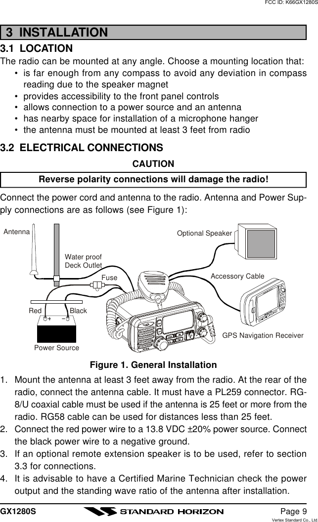
![GX1280S Page 1MATRIX GX1280S25 Watt VHF/FMMarine TransceiverOwner's ManuallSubmersiblelDSC distress call automatically broadcasts lat/long and vessel ID]lMARITEL DSC telephone capabilitylDSC position request function and NMEA data input/outputlLatitude/Longitude and SOG/COG display]lChannel name capabilitylVersatile user-programmable Scanning, Priority Scan and Dual WatchlNOAA Weather AlertlOne-button access to Channel 16 and 9lAccess to all US, Canadian and International channelslBig, back-lit display and keys]with GPS attachedFCC ID: K66GX1280SVertex Standard Co., Ltd.](https://usermanual.wiki/Yaesu-Musen/GX1280S/User-Guide-322201-Page-1.png)

![GX1280S Page 71 GENERAL INFORMATION1.1 INTRODUCTIONThe STANDARD HORIZON MATRIX is a VHF/FM transceiver designed foruse in the frequency range of 156.025 to 163.275 MHz. The MATRIX re-quires 13.8V for operation and has a switchable RF output power of 1 wattor 25 watts.The MATRIX is capable of RTCM SC101 DSC (Digital Selective Calling)operation and intercom operation with the use of an optional RAM mic(CMP25 remote-control speaker/microphone with display).The MATRIX operates on all currently-allocated marine channels which areswitchable for use with either USA, International, or Canadian regulations.It has an emergency channel 16 which can be immediately selected fromany channel by pressing the red [16/9] key. NOAA Weather channels canalso be accessed immediately by pressing the [WX] key with channel selec-tion.Other features of the transceiver include: scanning, priority scanning, sub-mersible speaker mic, high and low voltage warning, and GPS repeatability.1.2 FCC / INDUSTRY CANADA INFORMATIONThe following data pertaining to the transceiver is necessary to fill out thelicense application.Type Acceptance ........................................................................ FCC Part 80Output Power ............................................. 1 Watt (low) and 25 Watts (high)Emission........................................................................ 16K0G3E, 16K0G2BFrequency Range ................................................... 156.025 to 163.275 MHzFCC Type Number .................................................................... K66GX1280SIndustry Canada Type Approval.........................................511B-GX1280S VFCC ID: K66GX1280SVertex Standard Co., Ltd.](https://usermanual.wiki/Yaesu-Musen/GX1280S/User-Guide-322201-Page-7.png)
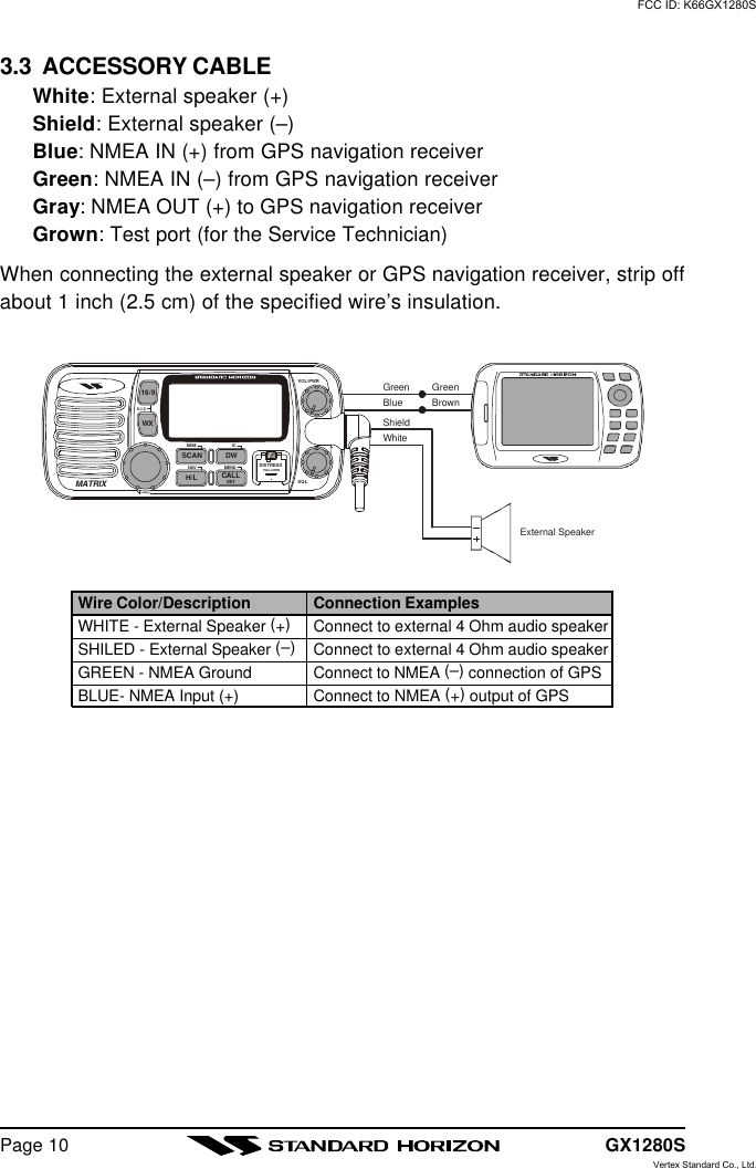
![GX1280SPage 124 CONTROLS AND INDICATORSNOTEThis section defines each control of the transceiver. See Figure 3 forlocation of controls. For detailed operating instructions refer to chapter5 of this manual.4.1 CONTROLS AND CONNECTIONSPOWER SWITCH/VOLUME CONTROLTurns the transceiver on and off as well as adjusts the audio volume. Toturn the transceiver on press and hold this knob until the LCD turns on.To turn it off, press and hold this knob until the LCD turns off. When thepower is turned on, the transceiver is set to the last selected channel.Secondary UseWhen the transceiver is turned on while the [SCAN] and [WX] keys areheld down, the internal microprocessor is reset. This clears the memoryand all user-programmed settings, such as scan memory, and priorityscan assignments. This condition is known as the default condition, thesame as when shipped from the factory. For a list of these defaults, seethe section on Resetting the Transceiver’s Microprocessor.NOTEResetting the microprocessor will not erase DSC MMSI and Direc-tory Call information.SQUELCH CONTROL (SQL)Sets the point at which random noise on the channel does not activatethe audio circuits but a received signal does. This point is called thesquelch threshold. Further adjustment of the squelch control will degradereception of wanted transmissions.CHANNEL SELECTOR KNOBRotary knob used to select channels and, to choose the item selection ofdifferent functions (such as the DSC operation). The [UP(p)] / [DOWN(q)]key on the microphone can also be used to select them.Secondary UseWhile holding down the [SCAN] Key and turning the CHANNEL selectorknob, you can confirm memory channels for scanning.FCC ID: K66GX1280SVertex Standard Co., Ltd.](https://usermanual.wiki/Yaesu-Musen/GX1280S/User-Guide-322201-Page-12.png)
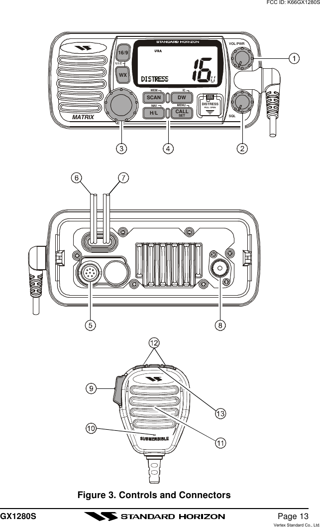
![GX1280SPage 14KEYPAD[16/9] KeyImmediately recalls channel 16 from any channel location. Holding downthis key recalls channel 9. Pressing the [16/9] key again reverts to theprevious selected working channel.Secondary usePlease see secondary use for the [WX] and [MEM] key.[WX] KeyImmediately recalls the previously selected NOAA weather channel fromany channel location.Secondary use1. Holding down the [16/9] key while pressing the [WX] key changesthe mode from USA to International or Canadian.NOTE: If position is displayed, this icon will be hidden.2. Holding down the [WX] and [SCAN] key while turning the power onresets the microprocessor and erases scan channels from memory.This clears the memory and establishes the factory-set defaults. Fora list of these defaults, see the section on Resetting the Transceiver’sMicroprocessor.[SCAN] Key1. Starts and stops scanning of programmed channels.2. If held while the [UP(p)] or [DOWN(q)] key on the microphone arepressed or CHANNEL selector knob on radio is turned, the radio willshow the channels programmed in scan memory. This function willnot work if the unit is scanning.NOTE: The priority channel is channel 16 only.[H/L] KeyToggles between high and low power. When the [H/L] key is pressedwhile the transceiver is on channel 13 or 67, the power will temporarilyswitch from LO to HI power until the PTT is released. The [H/L] key doesnot function on transmit inhibited and low power only channels.Secondary usePress and hold [H/L] key, when connected to the GPS receiver, the LCDdisplays Position Data, Time, SOG (Speed Over Ground), and COG(Course Over Ground) from the GPS.FCC ID: K66GX1280SVertex Standard Co., Ltd.](https://usermanual.wiki/Yaesu-Musen/GX1280S/User-Guide-322201-Page-14.png)
![GX1280S Page 15[DW] KeyWatches for a transmission on CH16 and another selected channel untileither signal is received. (Dual watch)NOTE: When the DSC SCANNING feature is enabled (see section 7.10DSC SCANNING), the radio watches for a transmission on CH16, an-other selected channel, and CH70 until either signal is received (Triplewatch).Secondary usePress and hold [DW] key, when the optional RAM Mic is connected, in-tercom operation will operate between radio and RAM Mic.[CALL/SET] KeyThe [CALL/SET] key functions as the enter key.Secondary usePress the [CALL/SET] key to access the DSC OPERATION menu. The“INDIVIDUAL CALL” and “ALL SHIPS CALL” functions can be accessedfrom the DSC OPERATION menu.Press and hold the [CALL/SET] key to access the RADIO SETUP orDSC SETUP menu. The following functions can be accessed in the menu.RADIO SETUP menu DSC SETUP menu[DISTRESS] KeyUsed to send a DSC Distress Call. To send the distress call see section6.2 (Sending a Distress Call).FCC ID: K66GX1280SVertex Standard Co., Ltd.](https://usermanual.wiki/Yaesu-Musen/GX1280S/User-Guide-322201-Page-15.png)
![GX1280SPage 16RAM MIC CONNECTORConnects the Remote Access Microphone (RAM MIC). Refer to section8.0 RAM MIC OPERATION.ACCESSORY CONNECTION CABLEConnects the radio to a GPS, and an external speaker.DC INPUT CABLEConnects the radio to a DC power supply of 13.8VANTENNA JACKConnects an antenna to the transceiver. Use a marine VHF antenna withan impedance of 50 ohms.PTT (Push-To-Talk) SWITCHKeys the transmitter when the transceiver is in radio mode. If the trans-ceiver is in the intercom operation mode, it activates the .microphone forthe inercom.MICROPHONETransmits the voice message with reduction of background noise.MICROPHONE SPEAKERThe same audio heard through internal radio speaker as heard throughmicrophone speaker.[UP(p)] / [DOWN(q)] KEYSThe [UP(p)] and [DOWN(q)] on the microphone function the same asthe CHANNEL selector knob on the front panel of the transceiver.[16/9] KeyPressing the [16/9] key immediately recalls channel 16 from any loca-tion. Press and hold the [16/9] key to recall channel 9. Pressing the[16/9] key again revert the radio to the previous select channel.FCC ID: K66GX1280SVertex Standard Co., Ltd.](https://usermanual.wiki/Yaesu-Musen/GX1280S/User-Guide-322201-Page-16.png)
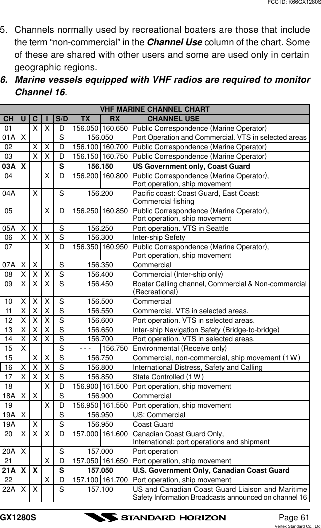
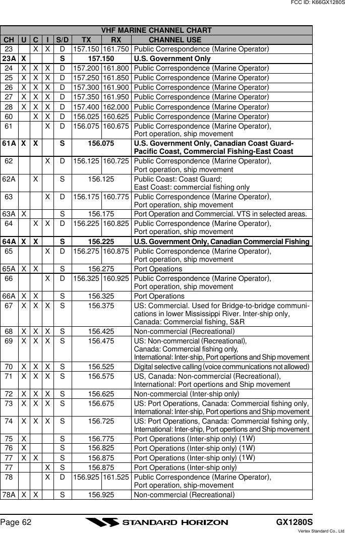
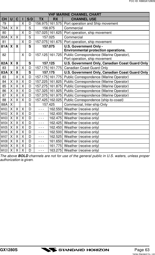
![GX1280SPage 185.4 SIMPLEX/DUPLEX CHANNEL USERefer to the VHF MARINE CHANNEL CHART (page 49) for instructions onuse of simplex and duplex channels.NOTEAll channels are factory-programmed in accordance with FCC (USA),Industry Canada (Canada), and International regulations. Mode of op-eration cannot be altered from simplex to duplex or vice-versa.5.5 USA, CANADA, AND INTERNATIONAL MODE1. To change the modes, hold the [16/9] key and press the [WX] key. Themode changes from USA to International to Canadian with each press ofthe [WX] key.2. “USA” will be displayed on the LCD for USA mode, “INTL” will be dis-played for International mode, and “CAN” will be displayed for Canadianmode.3. Refer to the VHF MARINE CHANNEL CHART (page ??) for allocatedchannels in each mode.5.6 NOAA WEATHER CHANNELS1. To receive a NOAA weather channel, press the [WX] key from any chan-nel. The transceiver will go to the last selected weather channel.2. Turn the CHANNEL selector knob on the radio or [UP(p)] / [DOWN(q)]keys on the microphone to select a different NOAA weather channel.3. To exit from the NOAA weather channels, press the [WX] key. The trans-ceiver returns to the channel it was on prior to a weather channel.FCC ID: K66GX1280SVertex Standard Co., Ltd.](https://usermanual.wiki/Yaesu-Musen/GX1280S/User-Guide-322201-Page-18.png)
![GX1280S Page 195.7 NOAA WEATHER ALERTIn the event of extreme weather disturbances, such as storms and hurri-canes, the NOAA (National Oceanic and Atmospheric Administration) sendsa weather alert accompanied by a 1050 Hz tone and subsequent weatherreport on one of the NOAA weather channels. When the Weater Aleart fea-ture is enabled (see section 7.4 WEATER ALERT), the transceiver is ca-pable of receiving this alert if the following is performed:1. Program NOAA weather channels into the transceiver’s memory for scan-ning. Follow the same procedure as for regular channels under section5.8.2. Press the [SCAN] key once to start memory scanning or hold down the[SCAN] key during memory scanning to start priority scanning.3. The programmed NOAA weather channels will be scanned along withthe regular-programmed channels. However, scanning will not stop on anormal weather broadcast unless a NOAA alert is received.4. When an alert is received on a NOAA weather channel, scanning willstop and the transceiver will emit a loud beep to alert the user of a NOAAbroadcast.5. Press the [WX] key to stop the alert tone and receive the weather report.NOTEIf the [WX] key is not pressed the alert tone will be emitted for 5 minutesand then the weather report will be received.NOTEThe Weather Aleart feature is also engaged while the transceiver isreceived on the one of the NOAA weather channel.FCC ID: K66GX1280SVertex Standard Co., Ltd.](https://usermanual.wiki/Yaesu-Musen/GX1280S/User-Guide-322201-Page-19.png)
![GX1280SPage 205.8 MEMORY SCANNING (M-SCAN)NOTE•During scanning, the dot matrix area of the LCD will show M-SCAN orP-SCAN depending on the scan mode selected.•If GPS position is displayed this icon will be hidden.1. Adjust the SQL knob until background noise disappears.2. Select a desired channel to be scanned using theCHANNEL selector knob. Press the [MEM] key,“MEM” will appear on the LCD which indicates thechannel has been programmed into the transceiv-ers memory.3. Repeat step 2 for all the desired channels to be scanned.4. To DELETE a channel from the transceiver’s memory, press and holdthe [MEM] key, “MEM” will disappear in the LCD.5. To start scanning, press the [SCAN] key. Scan-ning will proceed from the lowest to the highestprogrammed channel number and will stop on achannel when a transmission is received.6. The channel number will blink during reception.7. To stop scanning, press the [SCAN], [16/9], [WX], or PTT key.5.9 PRIORITY SCANNING (P-SCAN)1. Any channel can be set as the priority channel, other than weather chan-nels and channel 70. To set the priority channel,select the desired channel. Press and hold downthe [MEM] key until “P-CH” is shown on the dis-play.2. To select priority scanning, hold down the [SCAN] key until “P-SCAN”appears on the LCD during memory scanning. Scanning will proceedbetween the memorized channels and the priority channel. The prioritychannel will be scanned after each programmed channel.ø: When DSC Scanning method is enabled. Default is DSC scan is ON.3. The scanning will be performed while receivingthe MEM CH (memorized channel).4. To stop scanning, press the [SCAN], [16/9], [WX],or PTT key.MEM CH. CH. 16 øCH. 70 MEM CH. CH. 16 øCH. 70FCC ID: K66GX1280SVertex Standard Co., Ltd.](https://usermanual.wiki/Yaesu-Musen/GX1280S/User-Guide-322201-Page-20.png)
![GX1280S Page 21NOTETriple watch (T/W) means the radio is watching CH70 for DSC Calls.Dual watch (D/W) means the radio is not watching CH70 for DSC Calls.5.10 NAVIGATION INDICATIONThe transceiver has the ability to display the time, SOG and COG date, aswell as the vessel’s position (LAT/LON), if connected to a GPS receiver.1. Press and hold the [H/L] key to display positioninformation. If the GPS receiver receives no sig-nal, the display will be as shown in the illustrationon the right.2. To hide the position information, press the [H/L]key.NOTEThe TIME OFFSET should be set to local time in the DSC/RADIO setupmode when the radio is connected to the GPS navigation receiver. Toadjust TIME OFFSET to your local time, refer to section 7.11 TIME OFF-SET.5.11 VOICE SCRAMBLERIf privacy of communications is desired, a CVS2500 voice scrambler (VS)can be installed in the transceiver. Contact your Dealer to have a CVS2500installed. Refer to the section 7.8 DSC/RADIO SET UP mode to programthe voice scrambler.1. Turn on the transceiver.2. Select a channel that was programmed for scram-bler mode. (Example: the voice scrambler code isset 3.)ŸIf a channel is not set for the voice scrambler,the display will be as shown in the illustration atthe right.ŸIf a voice scrambler is canceled temporarily inthe “SETUP” menu, the display will be as shownin the illustration at the right.3. Monitor the channel before transmitting.4. Transmit the voice message. The signal sent will be scrambled.FCC ID: K66GX1280SVertex Standard Co., Ltd.](https://usermanual.wiki/Yaesu-Musen/GX1280S/User-Guide-322201-Page-21.png)
![GX1280SPage 225.14 RESETTING THE TRANSCEIVERÕS MICROPROCESSORResetting the microprocessor restores the initial, factory supplied conditionsin the transceiver. These are called the default conditions.To reset the microprocessor, first turn the transceiver off. Then while press-ing the [WX] and [SCAN] keys, turn the transceiver on. The default condi-tions are:ŸNo channels in the SCAN memory.ŸChannel 16 will be selected when the transceiver is turned on.ŸWX channel 01 will be recalled when the [WX] key is pressed.ŸKey beep will be on.NOTEResetting the microprocessor will not erase DSC MMSI and DirectoryCall Waiting information.FCC ID: K66GX1280SVertex Standard Co., Ltd.](https://usermanual.wiki/Yaesu-Musen/GX1280S/User-Guide-322201-Page-22.png)
![GX1280SPage 246.2 SENDING A DISTRESS CALLThe distress call automatically includes the vessel’s DSC MMSI and Lat/Lon position. Refer to section 7.9 (USER MMSI INPUT). The vessel’s posi-tion can be sent only if the transceiver is properly connected to an operatingGPS receiver.1. Lift the red spring loaded DISTRESS cover andpress the [DISTRESS] key. The “DISTRESS” menuwill appear on the LCD.2. Press and hold the [DISTRESS] or [CALL/SET]key for 3 seconds or more. Holding time will ap-pear on the LCD.3. When the distress signal is sent, “TX” icon will ap-pear on the LCD. After the message has been sent,the Distress Alarm will sound.6. The transceiver “shadow-watches” for a transmis-sion between CH16 and CH70 until an acknowl-edgment signal is received. “DISTRESS” and“WAITING” will appear on the LCD.7. If no acknowledgment is received, the distress callis repeated in 4 minute intervals until an acknowl-edgment is received.8. To cancel a Distress Call, press the [16/9] key, turn the CHANNEL selec-tor knob to select “CANCEL.” Then, press the [CALL/SET] key or turn offthe radio.9. When a distress acknowledgment is received, adistress alarm sounds and channel 16 is automati-cally selected.LCD shows ID and the answering type.RECEIVED ACK: acknowledgment signal is received.RECEIVED RLY: relay signal is received from other vessel or coast sta-tion.10.To cancel the alarm, press any key.NOTEWhen a GPS receiver with NMEA output is connected, the vessel’s po-sition is automatically transmitted with the distress call.FCC ID: K66GX1280SVertex Standard Co., Ltd.](https://usermanual.wiki/Yaesu-Musen/GX1280S/User-Guide-322201-Page-24.png)
![GX1280S Page 256.3 SENDING AN INDIVIDUAL CALLThis feature allows the user to contact another user vessel DSC and toautomatically switch the receiving DSC radio to a desired working channel.This feature is similar to calling a vessel on CH16 and requesting to go toanother channel. To send an individual call, see section 7.5 INDIVIDUALDIRECTORY SETUP. The individual call function allows you to transmit aDSC signal to a specific party only, prompting communication on a voicechannel.1. Select the traffic channel for voice communica-tion.2. Press the [CALL/SET] key. The “DSC OPERA-TION” menu will appear.3. Turn the CHANNEL selector knob to select “INDI-VIDUAL.” (To cancel, select “EXIT” with the CHAN-NEL selector knob or press the [16/9] key.)4. Press the [CALL/SET] key. The transceiver willbeep, and the “Individual directory” will appear.5. Turn the CHANNEL selector knob to select the“Individual” you want to contact.6. Press the [CALL/SET] key to transmit the indi-vidual DSC signal.7. After INDIVIDUAL CALL is transmitted, the trans-ceiver will wait 8 seconds for the acknowledgment.If the reply signal is not received, the transceiverwill transmit again.8. After the second INDIVIDUAL CALL is transmit-ted, if the reply signal is not received, the dot ma-trix area of the LCD will display “àSEND” to promptthe user to send the call again or exit the mode.9. When an individual call acknowledgment “able tocomply” is received, the established channel isautomatically selected and an alarm sounds.10.When an individual call acknowledgment with “un-able to comply” is received, the established channel is automaticallyselected.11. To cancel, select “EXIT” using the CHANNEL selector knob and pressthe [CALL/SET] key. This procedure can be also canceled by pressingthe [CALL/SET] key or [16/9] key.FCC ID: K66GX1280SVertex Standard Co., Ltd.](https://usermanual.wiki/Yaesu-Musen/GX1280S/User-Guide-322201-Page-25.png)
![GX1280SPage 266.4 SENDING A GROUP CallThis feature allows the user to contact a group of specific vessels usingDSC and to automatically switch to a desired channel. This feature allowsyou to transmit a DSC signal with group MMSI that has been set accordingto section 7.13 Group MMSI INPUT.1. Select the desired channel to use Group Call forvoice communications.2. Press the [CALL/SET] key. The “DSC OPERA-TION” menu will appear.3. Turn the CHANNEL selector knob to select“GROUP.” (To cancel, select “EXIT” with theCHANNEL selector knob or press [16/9] key.)4. Press the [CALL/SET] key. The transceiver willbeep, and the “Individual directory” will appear.5. Turn the CHANNEL selector knob to select the“Group” you want to contact.6. Press the [CALL/SET] key to transmit the GroupCall signal.8. When the Group Call signal is sent, the dot-matrixarea of the LCD will be as shown in the illustrationat the right.9. After the GROUP CALL is transmitted, all the ra-dios in the group will switch to the designated chan-nel.FCC ID: K66GX1280SVertex Standard Co., Ltd.](https://usermanual.wiki/Yaesu-Musen/GX1280S/User-Guide-322201-Page-26.png)
![GX1280S Page 276.5 SENDING AN ALL SHIPS CALLThe All Ships Call function allows contact to be established with other vesselstations without having their ID in the individual calling directory. Also, prior-ity for the call can be designated as Urgency or Safety.URGENCY Call: This type of call is used when a vessel may not truly be indistress, but have a potential problem that may lead to adistress situation.SAFETY Call: Used to transmit boating safety information to other ves-sels. This message usually contains information about anoverdue boat, debris in the water. Loss of a navigation aidor an important meteorological message.1. Select the traffic channel (for voice communica-tion).2. Press the [CALL/SET] key. The “DSC OPERA-TION” menu will appear.3. Turn the CHANNEL selector knob to select “ALLSHIPS.”4. Press the [CALL/SET] key. (To cancel this, turnthe CHANNEL selector knob to select “EXIT.”)5. Turn the CHANNEL selector knob to select thenature of call (“URGENCY” or “SAFETY”).6. Press the [CALL/SET] key to transmit the selectedtype of all ships DSC call.7. After the ALL SHIPS CALL is transmitted, the trans-ceiver will wait on CH16.FCC ID: K66GX1280SVertex Standard Co., Ltd.](https://usermanual.wiki/Yaesu-Musen/GX1280S/User-Guide-322201-Page-27.png)
![GX1280SPage 286.6 DSC STANDBYThe DSC Standby function allows the transceiver to reply to DSC calls withthe Unattended message and logs the calls in the call waiting directory (Thisfeature is similar to an answering machine). When set to the DSC Standbymode, voice traffic may still be monitored on the selected channel.1. Press the [CALL/SET] key. The “DSC OPERA-TION menu will appear.2. Turn the CHANNEL selector knob to select the“STANDBY.”3. Press the [CALL/SET] key.4. When an individual DSC call is received, the ra-dio will respond with the unattended message ifan operator cannot answer the call. The DSC callwill be logged into the radio’s call waiting direc-tory.5. To cancel this, press the [16/9] key.NOTEThis function is available as following;DSC SCAN is turned on, or the current channel is set to CH70 if DSCSCAN is turned off.6.7 CALL WAITING DIRECTORYThe DSC Call Waiting directory logs 10 received distress calls, and logs 20individual calls that are received and not answered within 5 minutes or whilethe radio is set on the DSC Standby function. Calls will be logged while busywith other communications as long as the transmitter is not keyed at thetime of the call. If the call is answered within 5 minutes the call will not belogged. When a call is logged, a message will appear on the LCD.NOTEWhen a DISTRESS CALL is received, this call will be logged on thedistress call waiting directory.FCC ID: K66GX1280SVertex Standard Co., Ltd.](https://usermanual.wiki/Yaesu-Musen/GX1280S/User-Guide-322201-Page-28.png)
![GX1280S Page 296.7.1 Operation of Distress Call Waiting1. Press the [CALL/SET] key. The “DSC OPERA-TION” menu will appear.2. Turn the CHANNEL selector knob to select “CALLWAIT.”3. Press the [CALL/SET] key.4. Turn the CHANNEL selector knob to select “DIS-TRESS.”5. Press the [CALL/SET] key to enter the “distresslog.”6. Turn the CHANNEL selector knob to select the“name.”7. Press the [CALL/SET] key to display the log data.8. To exit from Distress Call Waiting, press the [CALL/SET] key and select “EXIT.”6.7.2 Operation of Individual Call Waiting1. Press the [CALL/SET] key. The “DSC OPERA-TION” menu will appear.2. Turn the CHANNEL selector knob to select “CALLWAIT.”3. Press the [CALL/SET] key.4. Turn the CHANNEL selector knob to select “INDI-VIDUAL.”5. Press the [CALL/SET] key to enter the “individuallog.”6. Turn the CHANNEL selector knob to select the“name.”7. Press the [CALL/SET] key to display the “loggedcall.”8. Press the [CALL/SET] key to resend the INDI-VIDUAL CALL.9. To exit from Individual Call Waiting, select “EXIT”and press the [CALL/SET] key.FCC ID: K66GX1280SVertex Standard Co., Ltd.](https://usermanual.wiki/Yaesu-Musen/GX1280S/User-Guide-322201-Page-29.png)
![GX1280SPage 306.8 POSITION REQUESTThe position request mode may be used to show the position of anothervessel that has a DSC radio with this feature. The other vessel must have anoperating GPS receiver connected to its DSC transceiver and must not haveits transceiver set to deny position requests. (Refer the section 7.5 to enterinformation into the individual directory).1. Select a traffic channel, then press the [CALL/SET]key. The “DSC OPERATION” menu will appear inthe display.2. Turn the CHANNEL selector knob to select the“POS REQUEST.”3. Press [CALL/SET] key to show the Position re-quest directory. This directory uses the INDI-VIDUAL Directory information.4. Turn the CHANNEL selector knob to select aname.5. Press the [CALL/SET] key to transmit the posi-tion request DSC call.6. After a DSC position request is transmitted, thetransceiver remains on channel 70 until positiondata is received.7. The transceiver received position data from a ves-sel.8. If the transceiver does not receive a reply, the LCDwill display “>SEND” to prompt the user to send the call again or exit themode.9. If the transceiver received no position data, the LCD will show “NO PO-SITION DATA.”10.When the transceiver receives the requested position, the transceiveroutputs a NMEA DSC sentence which may be used by a Standard Hori-zon GPS chart plotter to show the vessels position.FCC ID: K66GX1280SVertex Standard Co., Ltd.](https://usermanual.wiki/Yaesu-Musen/GX1280S/User-Guide-322201-Page-30.png)
![GX1280S Page 316.9 POSITION SENDThe position send mode may be used to send your position to another radiowith this feature. Your vessel must have an operating GPS receiver con-nected to its MATRIX to send the position and must not have its transceiverset to deny position send.When other vessel receives your position, the trans-ceiver outputs a NMEA DSC sentence which may beused by a Standard Horizon GPS chart plotter to showyour position.1. Select a traffic channel, then press the [CALL/SET]key. The “DSC OPERATION” menu will appear inthe display.2. Turn the CHANNEL selector knob to select the“POS SEND.”3. Press the [CALL/SET] key to select the Positionsend directory. This directory uses the INDIVIDUALDirectory information.4. Turn the CHANNEL selector knob to select aname.5. Press the [CALL/SET] key to transmit your posi-tion DSC call.6. After your position DSC is transmitted, the resendmenu will appear. When you send your positionDSC again, select “SEND” and press the [CALL/SET] key. When you exit the mode, select “EXIT”and press the [CALL/SET] key.7. The transceiver returns to radio mode.FCC ID: K66GX1280SVertex Standard Co., Ltd.](https://usermanual.wiki/Yaesu-Musen/GX1280S/User-Guide-322201-Page-31.png)
![GX1280SPage 346.10.6.Receiving a position requestWhen a position request call is received from another vessel, a calling alarmwill sound and POS REQUEST will show in the LCD. Operation and trans-ceiver function differs depending on “POS REPLAY” in the “DSC SETUP”menu setting.Automatically reply:1. When a position request call is received, a calling alarm sounds 4 times.Then requested position coordinates are transmit-ted automatically.2. To exit from position request display, press anykey.Manually reply:1. When a position request call is received, the LCDwill be as shown in the illustration at the right.2. A calling alarm sounds 4 times. Then select typeof reply function “REPLY” or “NO REPLY” by us-ing the CHANNEL selector knob.3. When “REPLY” is selected, press the [CALL/SET]key. And the requested position coordinates willbe transmitted.4. To exit from position request display, press any key.FCC ID: K66GX1280SVertex Standard Co., Ltd.](https://usermanual.wiki/Yaesu-Musen/GX1280S/User-Guide-322201-Page-34.png)
![GX1280S Page 357 DSC / RADIO SETUPNOTEThe optional RAM MIC CMP can be change the SETUP menu. Refer topage ?? for datiles.7.1 LAMP ADJUSTING1. Press and hold down the [CALL/SET] key until“RADIO SETUP” menu appear.2. Press the [CALL/SET] key, then select “LAMP” inthe “RADIO SETUP” menu with the CHANNEL se-lector knob.3.Press the [CALL/SET] key.4. Turn the CHANNEL selector knob to select thedesired level. When “OFF” is selected, the lampis extinguished.5. Press the the [CALL/SET] key to store the selectedlevel.6. Turn the CHANNEL selector knob to select “EXIT,” then press the [CALL/SET] key to return to the normal operation.7.2 LCD CONTRUST1. Press and hold down the [CALL/SET] key until“RADIO SETUP” menu appear.2. Press the [CALL/SET] key, then select“CONTRUST” in the “RADIO SETUP” menu withthe CHANNEL selector knob.3. Press the the [CALL/SET] key.4. Turn the CHANNEL selector knob to select thedesired level. The contrust level can be set from“1” to “7.”5. Press the the [CALL/SET] key to store the selectedlevel.6. Turn the CHANNEL selector knob to select “EXIT,” then press the [CALL/SET] key to return to the normal operation.FCC ID: K66GX1280SVertex Standard Co., Ltd.](https://usermanual.wiki/Yaesu-Musen/GX1280S/User-Guide-322201-Page-35.png)
![GX1280SPage 367.3 TIME OFFSETSets the time difference between local time and UTC. Time is displayedwhen position (LAT/LON) is displayed by pressing the [H/L] key.1. Press and hold down the [CALL/SET] key until“RADIO SETUP” menu appear.2. Press the [CALL/SET] key, then select “TIME SET”in the “RADIO SETUP” menu with the CHANNELselector knob.3. Press the [CALL/SET] key.4. Turn the CHANNEL selector knob to select timeoffset from UTC. See illustration below to find youroffset time from UTC. If “0:00” is assigned, the timeis the same as UTC (Universal Time Coordinatedor GMT Greenwich Mean Time).5. Press the [CALL/SET] key to store the time offset.6. Tune the CHANNEL selector knob to select “EXIT,” then press the [CALL/SET] key to return to the normal operation.OFFSET TIME TABLEFCC ID: K66GX1280SVertex Standard Co., Ltd.](https://usermanual.wiki/Yaesu-Musen/GX1280S/User-Guide-322201-Page-36.png)
![GX1280S Page 377.4 KEY BEEP (ON/OFF)1. Press and hold down the [CALL/SET] key until“RADIO SETUP” menu appear.2. Press the [CALL/SET] key, then select “KEYBEEP” in the “RADIO SETUP” menu with theCHANNEL selector knob.3. Press the [CALL/SET] key.4. Turn the CHANNEL selector knob to select “ON”or “OFF.”5. Press the [CALL/SET] key to set the key beepcondition.6. Tune the CHANNEL selector knob to select “EXIT,”then press the [CALL/SET] key to return to the normal operation.NOTEEmergency alarm and beeps for DSC operation cannot be turned OFF.7.5 WX ALERT (ON/OFF)1. Press and hold down the [CALL/SET] key until“RADIO SETUP” menu appear.2. Press the [CALL/SET] key, then select “WXALERT” in the “RADIO SETUP” menu with theCHANNEL selector knob.3. Press the [CALL/SET] key.4. Turn the CHANNEL selector knob to select “ON”or “OFF.”5. Press the [CALL/SET] key to store the selectedsetting.6. Tune the CHANNEL selector knob to select “EXIT,”then press the [CALL/SET] key to return to the normal operation.7.6 VOICE SCRAMBLER1. Press and hold down the [CALL/SET] key until“RADIO SETUP” menu appear.2. Press the [CALL/SET] key, then select “SCRAM-BLER” in the “RADIO SETUP” menu with theCHANNEL selector knob.3. Press the [CALL/SET] key, then select “CODE” inthe “SCRAMBLER” menu with the CHANNEL se-FCC ID: K66GX1280SVertex Standard Co., Ltd.](https://usermanual.wiki/Yaesu-Musen/GX1280S/User-Guide-322201-Page-37.png)
![GX1280SPage 38lector knob.4Press the [CALL/SET] key, then turn the CHAN-NEL selector knob to change the scrambler code.The scrambler code can be set from “0” to “3” and“OFF.” When “OFF” is selected, the voice scram-bler is disabled.5. Press the [CALL/SET] key to store the selectedcode.6. Select “CHANNEL” in the “SCRAMBLER” menuwith the CHANNEL selector knob, then press the[CALL/SET] key.7. Turn the CHANNEL selector knob to change theScrambler channel.8. Press the [CALL/SET] key to store the selectedchannel. Repeat steps 6 and 7 to set other chan-nels.9.Press and hold down the [CALL/SET] key.10.Tune the CHANNEL selector knob to select “EXIT,” then press the [CALL/SET] key to return to the normal operation.NOTEThis menu will not appear unless a CVS2500 is installed.7.7 CH NAMING1. To select USA, INT or CANADA, press and holdthe [16/9] key and press [WX] key.2. Press and hold down the [CALL/SET] key until“RADIO “SETUP” menu appear.3. Press the [CALL/SET] key, then select “CH NAME”in the “RADIO SETUP” menu with the CHANNELselector knob.4. Press the [CALL/SET] key.5. Turn the CHANNEL selector knob to select thechannel to be named and press the [CALL/SET]key.6. Turn the CHANNEL selector knob scroll throughthe alphabet and 0 - 9.7. Press the [CALL/SET] key to enter the desiredletter and move the cursor one space to the right.FCC ID: K66GX1280SVertex Standard Co., Ltd.](https://usermanual.wiki/Yaesu-Musen/GX1280S/User-Guide-322201-Page-38.png)
![GX1280S Page 398. Repeat procedure until the name is complete. The name can consist ofup to twelve characters. If you do not use all twelvecharacter, press the [CALL/SET] key to move tothe next space. If you clear the previous letter,press the [H/L] key.9. Press and hold down the [CALL/SET] key to enter the name and exitfrom the “CHANNEL” menu. The LCD will return to the “SETUP” menu.10.If you want to enter the name of another channel, repeat steps 4 through9.11. Tune the CHANNEL selector knob to select “EXIT,” then press the [CALL/SET] key to return to the normal operation.7.8 TRUE MAGNETIC CHANGE1. Press and hold down the [CALL/SET] key until“RADIO SETUP” menu appear.2. Press the [CALL/SET] key, then select “TRUEMAG” in the “RADIO SETUP” menu with theCHANNEL selector knob.3. Press the [CALL/SET] key.4. Turn the CHANNEL selector knob to select “ON”or “OFF.”5. Press the [CALL/SET] key to store the selectedsetting.6. Tune the CHANNEL selector knob to select “EXIT,”then press the [CALL/SET] key to return to the normal operation.7.9 INDIVIDUAL DIRECTORY SETUP1. Press and hold down the [CALL/SET] key until“RADIO SETUP” menu appear.2. Turn the CHANNEL selector knob to select “DSCSETUP” menu.3. Press the [CALL/SET] key, then select “INDIV DIR”in the “DSC SETUP” menu with the CHANNELselector knob.4. Press the [CALL/SET] key, then select “ADD” inthe “INDIV DIR” menu with the CHANNEL selec-tor knob.5. Press the [CALL/SET] key.FCC ID: K66GX1280SVertex Standard Co., Ltd.](https://usermanual.wiki/Yaesu-Musen/GX1280S/User-Guide-322201-Page-39.png)
![GX1280SPage 406. Turn the CHANNEL selector knob to display thenext address number.(Example: The address number 01 - 04 have beenstored in the illustration at the right.) The addressnumber can be set from “01” to “30.”7. Press the [CALL/SET] key to store the address number.8. Turn the CHANNEL selector knob scroll through the alphabet and 0 - 9.9. Press the [CALL/SET] key to enter the desired letter and move the cur-sor one space to the right. Repeat procedure until the name is complete.The name can consist of up to eleven characters, if you do not use alleleven characters press the [CALL/SET] key to move to the next space.This method can also be used to enter a blank space in the name. Toclear the previous letter, press the [H/L] key.10.After the eleventh letter or space has been entered, press the [CALL/SET] key to advance to the MMSI (Maritime Mobile Service Identity Num-ber) number entry.11. Turn the CHANNEL selector knob to scroll through numbers, 0-9. Toenter the desired number and move one space to the right press the[CALL/SET] key. Repeat procedure until all nine space of MMSI numberare entered.12.To enter another individual address, repeat steps 4 through 11.13.After entering the MMSI number, tune the CHANNEL selector knob toselect “EXIT,” then press the [CALL/SET] key to return to the normaloperation.NOTESelecting “NEXT” or “EXIT” will automatically save the name and MMSInumber into memory.FCC ID: K66GX1280SVertex Standard Co., Ltd.](https://usermanual.wiki/Yaesu-Musen/GX1280S/User-Guide-322201-Page-40.png)
![GX1280S Page 417.10 INDIVIDUAL REPLY1. Press and hold down the [CALL/SET] key until“RADIO SETUP” menu appear.2. Turn the CHANNEL selector knob to select “DSCSETUP” menu.3. Press the [CALL/SET] key, then select “INDIVREPLY” in the “DSC SETUP” menu with theCHANNEL selector knob.4. Press the [CALL/SET] key.5. Turn the CHANNEL selector knob to select “AUTO”or “MANUAL.”6. Press the [CALL/SET] key to store the selectedsetting.7. Tune the CHANNEL selector knob to select “EXIT,”then press the [CALL/SET] key to return to thenormal operation.7.11 INDIVIDUAL ACK1. Press and hold down the [CALL/SET] key until“RADIO SETUP” menu appear.2. Turn the CHANNEL selector knob to select “DSCSETUP” menu.3. Press the [CALL/SET] key, then select “INDIVACK” in the “DSC SETUP” menu with the CHAN-NEL selector knob.4. Press the [CALL/SET] key.5. Turn the CHANNEL selector knob to select “ABLE”or “UNABLE.”6. Press the [CALL/SET] key to store the selectedsetting.7. Tune the CHANNEL selector knob to select “EXIT,”then press the [CALL/SET] key to return to thenormal operation.FCC ID: K66GX1280SVertex Standard Co., Ltd.](https://usermanual.wiki/Yaesu-Musen/GX1280S/User-Guide-322201-Page-41.png)
![GX1280SPage 427.12 INDIVIDUAL RINGER1. Press and hold down the [CALL/SET] key until“RADIO SETUP” menu appear.2. Turn the CHANNEL selector knob to select “DSCSETUP” menu.3. Press the [CALL/SET] key, then select “INDIVRING” in the “DSC SETUP” menu with the CHAN-NEL selector knob.4. Press the [CALL/SET] key.5. Turn the CHANNEL selector knob to select ring-ing time of a Individual Call. When “DEFAULT” isselected, the ringer rings for 3 minmutes continu-ously.6. Press the [CALL/SET] key to store the selectedsetting.7. Tune the CHANNEL selector knob to select “EXIT,”then press the [CALL/SET] key to return to the normal operation.7.13 GROUP MMIS INPUT1. Press and hold down the [CALL/SET] key until“RADIO SETUP” menu appear.2. Turn the CHANNEL selector knob to select “DSCSETUP” menu.3. Press the [CALL/SET] key, then select “GROUPDIR” in the “DSC SETUP” menu with the CHAN-NEL selector knob.4. Press the [CALL/SET] key, then select “ADD” inthe “GROUP DIR” menu with the CHANNEL se-lector knob.6. Press the [CALL/SET] key. The “Group MMIS”number will appear, and the first space will flash.7. Turn the CHANNEL selector knob to set the num-ber (0 to 9), then press the [CALL/SET] key todefine the setting.8. Repeat step 7 to set your Group MMIS (up to nine digits).9. Tune the CHANNEL selector knob to select “EXIT,” then press the [CALL/SET] key to return to the normal operation.FCC ID: K66GX1280SVertex Standard Co., Ltd.](https://usermanual.wiki/Yaesu-Musen/GX1280S/User-Guide-322201-Page-42.png)
![GX1280S Page 437.14 POSITION REQUEST REPLY1. Press and hold down the [CALL/SET] key until“RADIO SETUP” menu appear.2. Turn the CHANNEL selector knob to select “DSCSETUP” menu.3. Press the [CALL/SET] key, then select “POS RE-PLY” in the “DSC SETUP” menu with the CHAN-NEL selector knob.4. Press the [CALL/SET] key.5. Turn the CHANNEL selector knob to select “AUTO”or “MANUAL.” In “AUTO” mode, after a DSC POSRequest is received, the radio will automaticallytransmit your vessels position. In “MANUAL” mode,the display of the MATRIX will show who is re-questing the position.6. Press the [CALL/SET] key to store the selectedsetting.7. Tune the CHANNEL selector knob to select “EXIT,” then press the [CALL/SET] key to return to the normal operation.7.15 DSC SCANWhen the radio is shipped from the factory it is programmed so CH70 (theDSC channel) is scanned at all times. There is a selection in the SETUPMENU to disable the DSC SCAN. However, turning off DSC SCAN will dis-able the radio from receiving DSC calls (i.e.: Individual Call, All Ships Call,Distress Call and Position Requests). If you want to use any of the functionsthe selection must be left ON.To Change DSC SCAN Method:1. Press and hold down the [CALL/SET] key until“RADIO SETUP” menu appear.2. Turn the CHANNEL selector knob to select “DSCSETUP” menu.3. Press the [CALL/SET] key, then select “DSCSCAN” in the “DSC SETUP” menu with the CHAN-NEL selector knob.4. Press the [CALL/SET] key.5. Turn the CHANNEL selector knob to select “ON”or “OFF.”FCC ID: K66GX1280SVertex Standard Co., Ltd.](https://usermanual.wiki/Yaesu-Musen/GX1280S/User-Guide-322201-Page-43.png)
![GX1280SPage 446. Press the [CALL/SET] key to store the selectedsetting.7. Tune the CHANNEL selector knob to select “EXIT,”then press the [CALL/SET] key to return to thenormal operation.7.16 USER MMIS INPUT1. Press and hold down the [CALL/SET] key until“RADIO SETUP” menu appear.2. Turn the CHANNEL selector knob to select “DSCSETUP” menu.3. Press the [CALL/SET] key, then select “USERMMIS” in the “DSC SETUP” menu with the CHAN-NEL selector knob.4. Press the [CALL/SET] key. The “User MMIS” num-ber will appear, and the first space will flash.5. Turn the CHANNEL selector knob to select firstnumber of your MMSI, then press the [CALL/SET]key to define the setting.6. Repeat step 5 to set your MMIS (up to nine digits).7. Tune the CHANNEL selector knob to select “EXIT,” then press the [CALL/SET] key to return to the normal operation.NOTEUser MMSI can be input only twice. If the user tries to input MMSI morethan twice, the radio will show the display on the right. If the user needsto change the MMSI more than twice, the transceiver will have to besent to Factory Service. Refer to the section 10.2 FACTORY SERVICE.FCC ID: K66GX1280SVertex Standard Co., Ltd.](https://usermanual.wiki/Yaesu-Musen/GX1280S/User-Guide-322201-Page-44.png)
![GX1280S Page 458 RAM MIC OPERATIONIf the optional RAM Mic (CMP25) is connected to the remote microphoneconnector on the transceiver’s rear panel, the transceiver can use the re-mote control operation except for a few functions. The RAM Mic has a maxi-mum range of 50 feet (15 m) with the use of two 10-foot extension cables(CT-100). The intercom operation can be used between the RAM Mic andthe transceiver.8.1 RAM MIC CONTROLS AND CONNECTIONSSQUELCH CONTROL (SQL)Activates the squelch adjusting mode.Press this key to activate the squelch adjusting mode. Press themicrophone’s [p] or [q] key to adjust the squelch.When this key is pressed and held down for 1 second or more, the squelchis turned off.SCAN DWNAVWXCALLSETMEM ICU.I.CMENU169FCC ID: K66GX1280SVertex Standard Co., Ltd.](https://usermanual.wiki/Yaesu-Musen/GX1280S/User-Guide-322201-Page-45.png)
![GX1280SPage 46VOLUME KEY (VOL)Activates the volume adjusting mode.Press this key to activate the volume adjusting mode. Press themicrophone’s [p] or [q] to adjust the volume.POWER SWITCH (PWR)Press and hold down this key to turn to the transceiver and RAM Mic onand off.PTT (Push-To-Talk) SWITCHActivates transmission.[H/L] KEYToggles between high and low power. When the [H/L] key is pressedwhile the transceiver is on channel 13 or 67, the power will temporarilyswitch from LO to HI power until the PTT is released. The [H/L] key doesnot function on transmit inhibited and low power only channels.[p](UP)/[q](DOWN) KEYThese keys used to select channels, adjusts the volume and squelchlevel, and to choose the item selection of different functions (such as theDSC operation). In many ways, these keys emulate the function of thetransceiver’s CHANNEL selector knob.[16/9] KEYImmediately recalls channel 16 from any channel location. Holding downthis key recalls channel 9. Pressing the [16/9] key again reverts to theprevious selected working channel.Secondary usePlease see secondary use for the [WX] and [MEM] key.KEY PAD[SCAN] Key1. Starts and stops scanning of programmed channels.2. If held while the [UP(p)] or [DOWN(q)] key on the microphone arepressed or CHANNEL selector knob on radio is turned, the radio willshow the channels programmed in scan memory. This function willnot work if the unit is scanning.NOTE: The priority channel is channel 16 only.FCC ID: K66GX1280SVertex Standard Co., Ltd.](https://usermanual.wiki/Yaesu-Musen/GX1280S/User-Guide-322201-Page-46.png)
![GX1280S Page 47[CALL/SET] KeyThe [CALL/SET] key functions as the enter key.Secondary usePress the [CALL/SET] key to access the DSC OPERATION menu.Press and hold the [CALL/SET] key to access the SETUP menu.[DW] KeyWatches for a transmission on CH16 and another selected channel untileither signal is received. (Dual watch)NOTE: When the DSC SCANNING feature is enabled (see section 7.10DSC SCANNING), the radio watches for a transmission on CH16, an-other selected channel, and CH70 until either signal is received (Triplewatch).Secondary usePress and hold [DW] key, intercom operation will operate between radioand RAM Mic.[NAV] KeyPress and hold this key, when connected to the GPS receiver, the LCDdisplays Position Data, Time, SOG (Speed Over Ground), and COG(Course Over Ground) from the GPS.[WX] KeyImmediately recalls the previously selected NOAA weather channel fromany channel location.Secondary use1. Holding down the [16/9] key while pressing the [WX] key changesthe mode from USA to International or Canadian.NOTE: If position is displayed, this icon will be hidden.2. Holding down the [WX] and [SCAN] key while turning the power onresets the microprocessor and erases scan channels from memory.This clears the memory and establishes the factory-set defaults. Fora list of these defaults, see the section on Resetting the Transceiver’sMicroprocessor.[DISTRESS] KEYUsed to send a DSC Distress Call. To send the distress call see section6.2 (Sending a Distress Call).FCC ID: K66GX1280SVertex Standard Co., Ltd.](https://usermanual.wiki/Yaesu-Musen/GX1280S/User-Guide-322201-Page-47.png)
![GX1280SPage 488.2 INTERCOM OPERATION8.2.1 Communication1. Press and hold the [DW] key while in the “RADIO” mode, the mode ischanged to “INTERCOM” mode. If press and hold the [DW] key againthe mode will revert to “RADIO” mode.2. “IC” is displayed on both the transceiver and the RAM Mic when the“INTERCOM” operation is activated.3. Press the PTT switch. The “TX” indicator is displayed.NOTEA warning beep is emitted when the RAM Mic PTT switch is pressedwhile the transceiver microphone’s PTT switch is pressed.4. Speak slowly and clearly into the microphone, hold the microphone about1/2 inch away from your mouth.5. When finished, release the PTT switch.8.2.2 CallingHold down the [DW] key for 1 second or more, when the “INTERCOM” op-eration is activated. A calling beep is emitted twice from the transceiverspeaker.8.3 DSC/RADIO SETUP MODEThe CMP25 can be setup the all DSC/RADIO setup menu (refer to section7 “DSC/RADIO SETUP” for details), as well. However, the LAMP, CON-TRAST, and KEY BEEP menu item which is accessed from the CMP25 onlyworks to the CMP25’s display and speaker only. In other wards, the LAMP,CONTRAST, and KEY BEEP menu item which is accessed from the radioonly works to the radio’s display and speaker.Here is the genenal procedures for the setup of the DSC/RADIO Setup modefrom the CMP25:1. Press and hold down the [CALL/SET] key until “RADIO SETUP” menuappear.2. Press the [p]/[q] key to select “RADIO SET” or “DSC SETUP” menu.3. Press the [CALL/SET] key, then select the menu item you wish to workon by pressing the [p]/[q] key.4. Press the [CALL/SET] key.5. Press the [p]/[q] key to change the value or condition for the menuitem, then press the [CALL/SET] key to save the new setting.FCC ID: K66GX1280SVertex Standard Co., Ltd.](https://usermanual.wiki/Yaesu-Musen/GX1280S/User-Guide-322201-Page-48.png)
![GX1280S Page 496. Press the [p]/[q] key to select “EXIT,” then press the [CALL/SET] key toreturn to the normal operation.FCC ID: K66GX1280SVertex Standard Co., Ltd.](https://usermanual.wiki/Yaesu-Musen/GX1280S/User-Guide-322201-Page-49.png)