Yaesu Musen VX-2500U UHF Transceiver User Manual Manual
Yaesu Musen Co., Ltd. UHF Transceiver Manual
UserManual.wiki
>
Yaesu Musen
>
VX 2500U User Manual
Manual
Navigation menu
Upload a User Manual
Namespaces
Wiki Guide
HTML
PDF
Info
Views
User Manual
Discussion / Help
Navigation
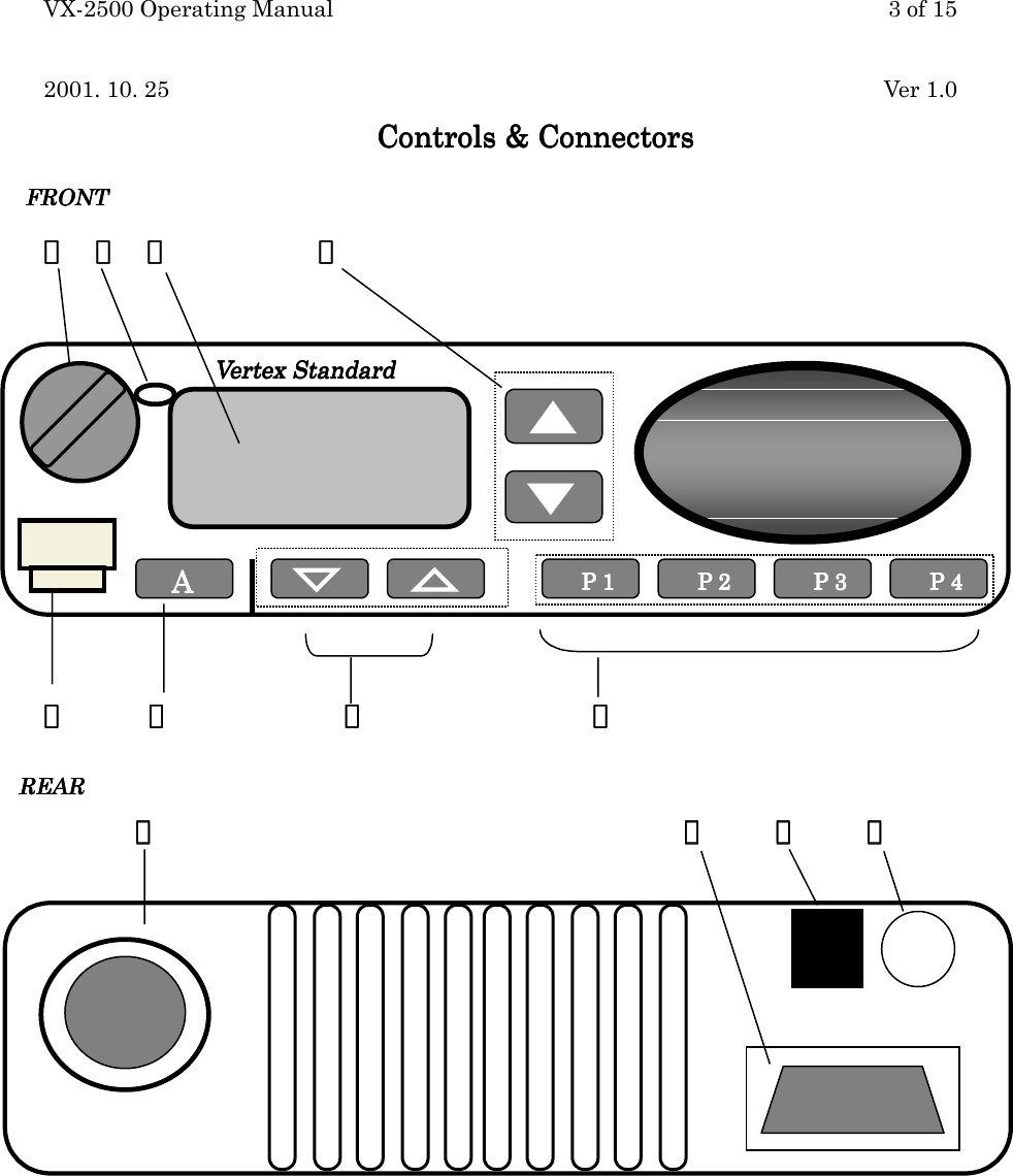
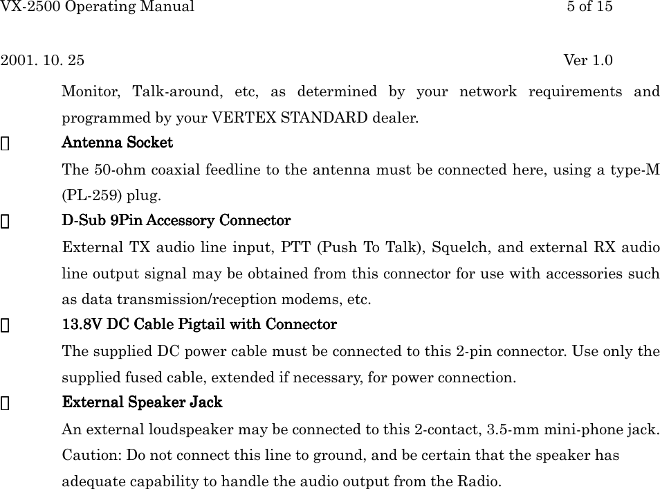
![VX-2500 Operating Manual 4 of 152001. 10. 25 Ver 1.0Important!Important!Important!Important! – All buttons located on the Front Panel are Programmable Function Button (PFProgrammable Function Button (PFProgrammable Function Button (PFProgrammable Function Button (PFbutton) button) button) button) determined by your network requirements and programmed by your VERTEXSTANDARD dealer. Following instruction is along with nominal button programming.①①①①VOL. / PWR KnobVOL. / PWR KnobVOL. / PWR KnobVOL. / PWR KnobRotate the knob to turn the transceiver ON and OFF and set the volume of thereceiver.②②②②Busy / Busy / Busy / Busy / TXTXTXTX Indicator Indicator Indicator Indicator[Conventional][Conventional][Conventional][Conventional]This lamp glows red when the radio is transmitting and glows green when thechannel is busy.Steady Green : Busy ChannelBlinking Green : Tone Squelch in defeated conditionSteady Red : Transmission in Progress[LTR Trunking][LTR Trunking][LTR Trunking][LTR Trunking]This lamp glows red when the radio is transmitting and glows green when the Systemis busy (Indicating all channels of the System are busy.)Steady Green : System BusySteady Red : Transmission in Progress③③③③LCD (Liquid Crystal Display)LCD (Liquid Crystal Display)LCD (Liquid Crystal Display)LCD (Liquid Crystal Display)The display include an 8-character alpha-numeric section showing System and Groupnames, status and identity information, and error messages. Additional indicators onthe display show priority channel assignments and scan include / exclude selection.④④④④▲▲▲▲・▼ ・▼ ・▼ ・▼ Button [Programmable Function Button ]Button [Programmable Function Button ]Button [Programmable Function Button ]Button [Programmable Function Button ]Pressing these buttons changes the current Group (and displayed group number orname). Holding this button for more than 1/2 second causes the function to repeat.⑤⑤⑤⑤Microphone JackMicrophone JackMicrophone JackMicrophone JackConnect the microphone plug to this jack.⑥⑥⑥⑥A Button [Programmable Function Button ]A Button [Programmable Function Button ]A Button [Programmable Function Button ]A Button [Programmable Function Button ]This button can be set up for special applications, such as high/low power selection,monitor, Talk-around, etc, as determined by your network requirements andprogrammed by your VERTEX STANDARD dealer.⑦⑦⑦⑦▽▽▽▽・△ ・△ ・△ ・△ Button [Programmable Function Button ]Button [Programmable Function Button ]Button [Programmable Function Button ]Button [Programmable Function Button ]Pressing these buttons changes the current System (and displayed group number orname). Holding this button for more than 1/2 second causes the function to repeat.⑧⑧⑧⑧P1 to P4 [ProgrP1 to P4 [ProgrP1 to P4 [ProgrP1 to P4 [Programmable Function Button ]ammable Function Button ]ammable Function Button ]ammable Function Button ]This button can be set up for special applications, such as High/Low power selection,](https://usermanual.wiki/Yaesu-Musen/VX-2500U/User-Guide-178260-Page-4.png)
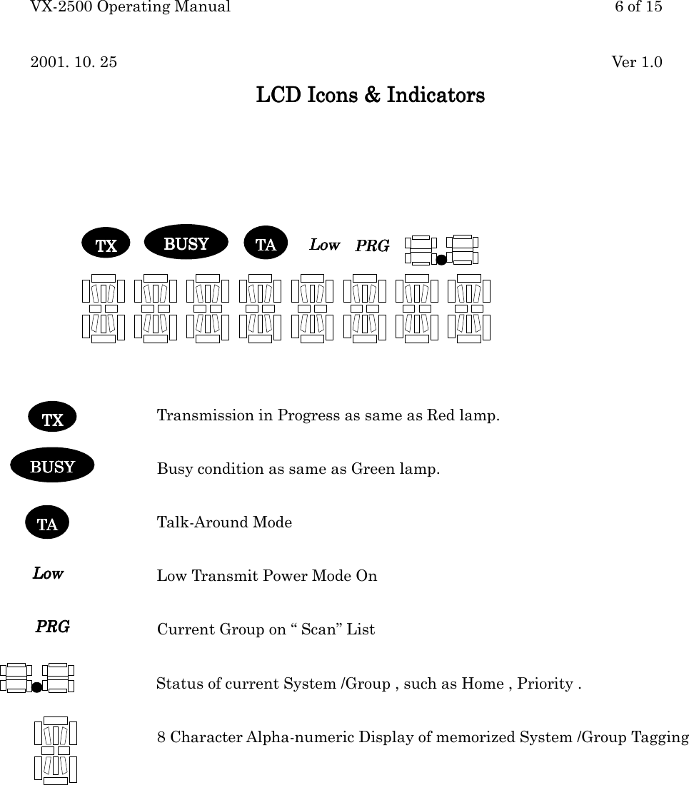
![VX-2500 Operating Manual 7 of 152001. 10. 25 Ver 1.0Basic Operation of the TransceiverBasic Operation of the TransceiverBasic Operation of the TransceiverBasic Operation of the TransceiverImportant!Important!Important!Important! - Before turning on the radio the first time, confirm that the power connectionshave been made correctly and that a proper antenna is connected to the antenna jack.Overview - Overview - Overview - Overview - Your Authorized VERTEX STANDARD Dealer can program your Radio forTrunking or Conventional format.Switching Power ON/OFFSwitching Power ON/OFFSwitching Power ON/OFFSwitching Power ON/OFFRotate the VOL. / PWR KnobVOL. / PWR KnobVOL. / PWR KnobVOL. / PWR Knob turn on the radio. The display will become illuminated. Press the▲▲▲▲・▼ ・▼ ・▼ ・▼ ButtonButtonButtonButton to choose the desired operating Group. A Group name will appear on the display.If you want to select the operating Group from a different System, press the ▽▽▽▽・△ ・△ ・△ ・△ ButtonButtonButtonButton toselect the System you want before selecting the operating Group.Setting the VolumeSetting the VolumeSetting the VolumeSetting the VolumeTurn the VOL. / PWR KnobVOL. / PWR KnobVOL. / PWR KnobVOL. / PWR Knob clockwise to increase the volume, and counterclockwise to decreaseit.[Conventional[Conventional[Conventional[Conventional System System System System]]]]If no signal is present, press and hold in the MON button more than 1/2 seconds; backgroundnoise will now be heard, and you may use this to set the VOL. / PWR KnobVOL. / PWR KnobVOL. / PWR KnobVOL. / PWR Knob for the desiredaudio level. Press the MON button again to quiet the noise and resume normal (quiet)monitoring.[Trunking[Trunking[Trunking[Trunking System System System System]]]]If no signal is present, press the MON button, the bass sound will be heard. And you may usethis to set the VOL. / PWR KnobVOL. / PWR KnobVOL. / PWR KnobVOL. / PWR Knob for the desired audio level.TransmittingTransmittingTransmittingTransmitting[[[[Conventional SystemConventional SystemConventional SystemConventional System]]]]1. In conventional mode, IT IS A FCC REQUIRMENT TO MONITOR A CHANNEL BEFORETRANSMITTING. Press the button programmed for monitoring. Listen for channelactivity.2. When receiving a call, Transmit only after the incoming call ends. The radio cannotreceive a call and transmit simultaneously.3. Press the PTT key. When a channel is available, the TXLED will glow red. The radio isnow transmitting and a voice message can be delivered. For best transmission, speak intothe microphone from a distance of 1- 1/2 to 2 inches. Release the PTT key after eachtransmission.4. If Busy Channel Lockout has been programmed for a channel, the radio will not transmit](https://usermanual.wiki/Yaesu-Musen/VX-2500U/User-Guide-178260-Page-7.png)
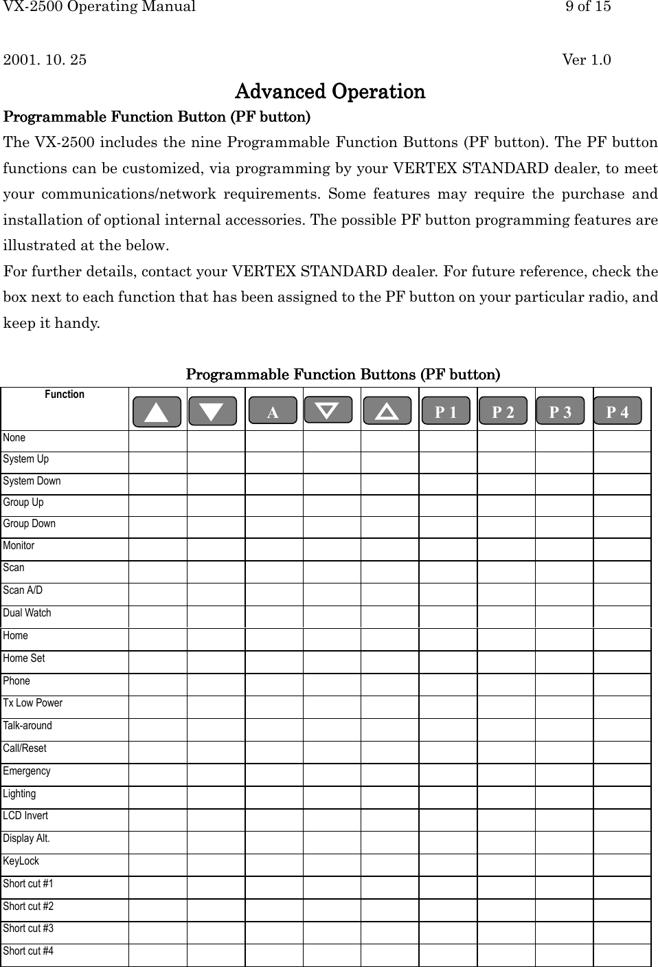
![VX-2500 Operating Manual 8 of 152001. 10. 25 Ver 1.0when a carrier is present. Instead, the radio will give a Continuos low-pitched tone whilethe PTT key is pressed. Release the PTT key and wait for channel activity to stop.5. If CTCSS or Digital-Coded Squelch (DCS) Lockout has been programmed for a channel, theradio can transmit only when there is no carrier being received or when the carrier beingreceived includes the correct CTCSS tone or DCS code.[[[[Trunking SystemTrunking SystemTrunking SystemTrunking System]]]]1. Press the PTT key. When a channel is available, the TX LED will glow red steadily. Theradio is now transmitting and a voice message can be delivered.2. If all channels are busy, a continuous tone will be heard and BUSY BUSY BUSY BUSY will appear on theLCD when the PTT key is pressed. Release the PTT key. When a channel becomesavailable, BUSY BUSY BUSY BUSY will disappear from the LCD, and a beep will be heard from the radio.Immediately press the PTT key to hold the channel. If the TX LED glows red, deliver thevoice message. If BUSYBUSYBUSYBUSY is displayed, repeat this step until a channel becomes available.3. If the radio is out of range during the transmitting attempt, slow beeps will be heardfollowed by a continuous tone. The in-range symbol will not be displayed on the LCD.Automatic Automatic Automatic Automatic Time-Out TimerTime-Out TimerTime-Out TimerTime-Out TimerIf the selected channel has been programmed for automatic time-out, you must limit the lengthof each transmission. While transmitting, a beep will sound five seconds before time-out.Another beep will sound just before the deadline; the “TX” indicator will disappear andtransmission will cease soon thereafter. To resume transmitting, you must release the PTT andwait for the “penalty timer” to expire (if you press the PTT before this timer expires, the timerrestarts, and you will have to wait another “penalty” period)](https://usermanual.wiki/Yaesu-Musen/VX-2500U/User-Guide-178260-Page-8.png)
![VX-2500 Operating Manual 10 of 152001. 10. 25 Ver 1.0Advanced OperationAdvanced OperationAdvanced OperationAdvanced OperationDescription of Operating FunctionsDescription of Operating FunctionsDescription of Operating FunctionsDescription of Operating FunctionsGroup ScanGroup ScanGroup ScanGroup ScanThe Scanning feature is used to monitor multiple Groups (channels) programmed into thetransceiver. While scanning, the transceiver will check each Group (channel) for the presenceof a signal on Conventional System or ID on the Trunking System, and will stop on aGroup(channel) if a signal or correct ID is present.To activate scanning:To activate scanning:To activate scanning:To activate scanning: Press the assigned PF button of the ScanScanScanScan momentarily to activate scanning. The scanner will search the Groups (channels) of the each System, looking for active ones;it will pause each time it finds a Group (channel) on which someone is speaking.To stop scanning:To stop scanning:To stop scanning:To stop scanning: Press the assigned PF button of the ScanScanScanScan. Operation will revert to the programmed Revert groupRevert groupRevert groupRevert group.Note: Your dealer may have programmed your radio to stay on one of the following channels ifyou press the PTTPTTPTTPTT switch during scanning pause:• Current Group (“Talk Back”)• “Last Busy” Group• “Priority” Group• “Home” Group• “Scan Start” GroupDual WatchDual WatchDual WatchDual Watch [only available on Conventional System]The Dual Watch feature is similar to the ScanScanScanScan feature, except that only two channels aremonitored: The current operating channel; and The “Priority” Group(channel.)To activate Dual WatchTo activate Dual WatchTo activate Dual WatchTo activate Dual Watch: Press the assigned PFPFPFPF button of the Dual WatchDual WatchDual WatchDual Watch. The scanner will search the two channels; it will pause each time it finds a channel onwhich someone is speaking.To stop Dual WatchTo stop Dual WatchTo stop Dual WatchTo stop Dual Watch: Press the assigned PFPFPFPF button of the Dual WatchDual WatchDual WatchDual Watch. Operation will revert to the revert Group which is programmed.](https://usermanual.wiki/Yaesu-Musen/VX-2500U/User-Guide-178260-Page-10.png)
![VX-2500 Operating Manual 12 of 152001. 10. 25 Ver 1.0scanning list).To edit the User Scan list, press and hold the button (assigned to the Group Up/Down function)to delete the current Memory Group from the Scanning. Alternatively, press and hold theassigned of the ScanScanScanScan A/D A/D A/D A/D for one second to delete the Current Memory channel from theScanning.When you delete a Group or channel, “PRGPRGPRGPRG” icon on the LCD will disappear on the LCD for onesecond after pressing the assigned button. To restore a particular channel to your scanning list,press and hold in the button again for one second; “PRGPRGPRGPRG” icon will appear on the LCD for onesecond after pressing the button.Call/Reset [only available on Conventional system]This feature, if enabled, allows the user to change the 3-digit Page Call code, used to call othersimilarly-equipped stations. Press the Dealer-assigned button, followed by the three digitsrepresenting the Page Call code of the station you wish to call. Three tones will be heard afterthe last button is pressed (the new code will now be transmitted).The receiver squelch of the other station will be opened, and you can begin communication.Speed DialSpeed DialSpeed DialSpeed DialYour Dealer may have pre-programmed Auto-Dial telephone number memories into yourradio.EmergencyEmergencyEmergencyEmergency[only available on Conventional system]The VX-VX-VX-VX-2525252500000000 Radio includes an “Emergency” feature which may be useful if you have someonemonitoring on the same frequency as your transceiver’s channel. For further details contactyour VERTEX STANDARD dealer.ARTS (Auto Range ARTS (Auto Range ARTS (Auto Range ARTS (Auto Range Transpond System)Transpond System)Transpond System)Transpond System)This system is designed to inform you when you and another ARTS-equipped station arewithin communication range.During ARTS operation, your radio automatically transmits for about 1 second every 25seconds (the interval is programmed by the Dealer) in an attempt to shake hands with theother station.If you move out of range for more than two minutes, your radio senses that no signal has beenreceived, a ringing beeper will sound, and “OUT OF SERVICE” will scroll on the LCD. If yousubsequently move back into range, as soon as the other station transmits, your beeper willsound, and “IN SERVICE” will scroll on the LCD.](https://usermanual.wiki/Yaesu-Musen/VX-2500U/User-Guide-178260-Page-12.png)
![VX-2500 Operating Manual 13 of 152001. 10. 25 Ver 1.0DTMF Paging SystemDTMF Paging SystemDTMF Paging SystemDTMF Paging System [only available on conventional system]This system allows paging and selective calling, using DTMF tone sequences.When your radio is paged by a station bearing a tone sequence which matches yours, yourradio’s squelch will open and the alert ringer will sound.The three-digit code of the station which paged you will be displayed on your radio’s LCD.](https://usermanual.wiki/Yaesu-Musen/VX-2500U/User-Guide-178260-Page-13.png)