Yaesu Musen VX-2500V VHF FM Mobile Transceiver User Manual C DATA VX 2500 VX 2500 p65
Yaesu Musen Co., Ltd. VHF FM Mobile Transceiver C DATA VX 2500 VX 2500 p65
UserManual.wiki
>
Yaesu Musen
>
VX 2500V User Manual
users manual
Navigation menu
Upload a User Manual
Namespaces
Wiki Guide
HTML
PDF
Info
Views
User Manual
Discussion / Help
Navigation
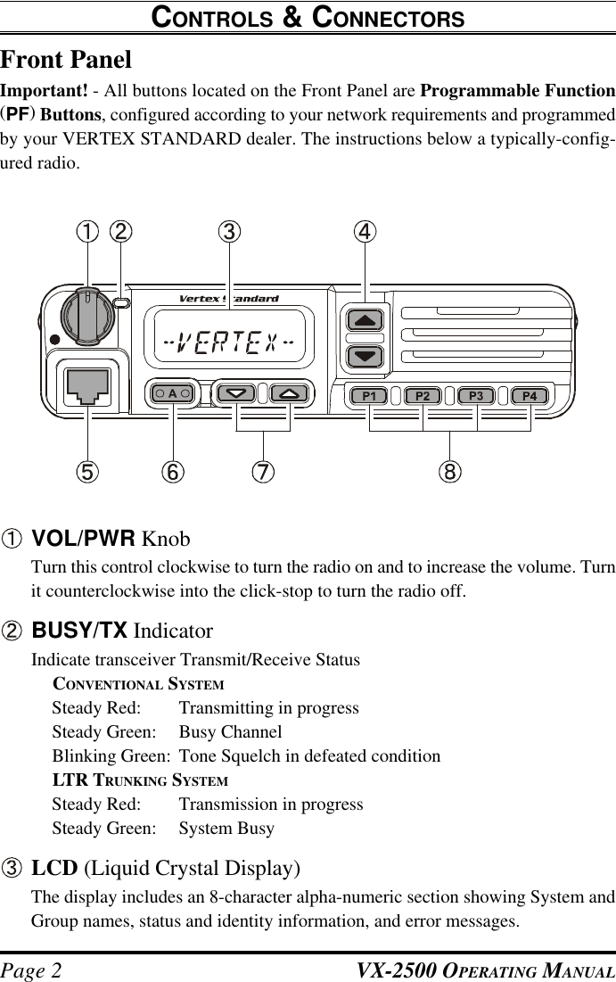
![VX-2500 OPERATING MANUAL Page 3[q]/[p] Buttons (Programmable Function Buttons)Pressing either button changes the current group (and displayed group numberor name). Holding a button for more than 1/2 second causes the function torepeat.Microphone JackConnect the microphone plug to this jack.[A] Button (Programmable Function Button)This button can be set up for special applications, such as High/Low power se-lection, Monitor, Talk-Around, etc, as determined by your network requirementsand programmed by your VERTEX STANDARD dealer.[s]/[r] Buttons (Programmable Function Buttons)Pressing either button changes the current system (and displayed system numberor name). Holding a button for more than 1/2 second causes the function torepeat.[P1] - [P4] Buttons (Programmable Function Buttons)These buttons can be set up for special applications, such as High/Low powerselection, Monitor, Talk-Around, etc, as determined by your network require-ments and programmed by your VERTEX STANDARD dealer.CONTROLS & CONNECTORSCurrent Group on “Scan” ListLCD Icons & Indicators8-Character Alpha-Numeric DisplayTransmission in progress,(follows Red BUSY/TX in-dicator).Busy Channel (followsGreen BUSY/TX indicator). Talk-Around EnabledLow TX PowerHorn Function ActivateHome System/Group](https://usermanual.wiki/Yaesu-Musen/VX-2500V/User-Guide-275622-Page-5.png)
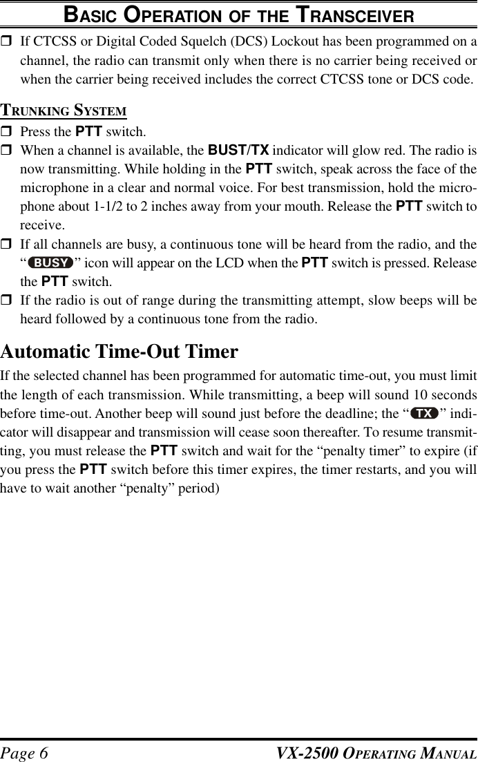
![VX-2500 OPERATING MANUAL Page 5BASIC OPERATION OF THE TRANSCEIVERImportant! - Before turning on the radio the first time, confirm that the power con-nections have been made correctly and that a proper antenna is connected to theantenna jack.Overview - Your authorized VERTEX STANDARD Dealer can program your radiofor Trunking or Conventional format.Switching Power ON/OFFrTurn the VOL/PWR knob turn on the radio. The display will become illumi-nated.rPress the [q]/[p] button to choose the desired operating group. A group namewill appear on the display. If you want to select an operating group from a differ-ent system, press the [s]/[r] button to select the system you want before select-ing the operating group.Setting the VolumerTurn the VOL/PWR knob clockwise to increase the volume, and counterclock-wise to decrease it.TransmittingCONVENTIONAL SYSTEMrIn conventional mode, monitor the channel and make sure it is clear.THIS IS AN FCC REQUIRMENT!Press the PF button which is programmed to the Monitor feature to listen forchannel activity.rWhen receiving a call, transmit only after the incoming call ends. The radio can-not receive a call and transmit simultaneously.rPress the PTT switch.rIf the channel is clear, the BUSY/TX indicator will glow red. The radio is nowtransmitting. While holding in the PTT switch, speak across the face of the mi-crophone in a clear and normal voice. For best transmission, hold the microphoneabout 1-1/2 to 2 inches away from your mouth. Release the PTT switch to re-ceive.rIf the Busy Channel Lockout feature has been programmed on a channel, theradio will not transmit when a carrier is present. Instead, the radio will generate acontinuous low-pitched tone while the PTT switch is pressed. Release the PTTswitch and wait for the channel to be clear of activity.](https://usermanual.wiki/Yaesu-Musen/VX-2500V/User-Guide-275622-Page-7.png)
![VX-2500 OPERATING MANUALPage 8Description of Operating FunctionsSYSTEM UP/SYSTEM DOWN (SYSTEM SELECTION)The VX-2500 is capable of separating its 250 memory groups into any of 32 systems.There is no limit as to the number of groups which may be assigned to each system.The Dealer will have made the system assignment at the time of group programming.rPress the assigned PF button (generally the [s]/[r] button) to change the sys-tem. Once the desired system is reached, press the PF button which is assigned tothe Group Up/Group Down feature (generally the [q]/[p] button) to select thedesired group within the selected system.GROUP UP/GROUP DOWN (GROUP SELECTION)Press the assigned PF button (generally the [q]/[p] button) to select a differentgroup within the current system.MONITORPress the assigned PF button momentarily to cancel CTCSS- and DCS-controlledsquelch; the BUSY/TX indicator will blink green. Press and hold this button for 1.5seconds to hear background noise (unmute the audio); the BUSY/TX indicator willglow green.ADVANCED OPERATION](https://usermanual.wiki/Yaesu-Musen/VX-2500V/User-Guide-275622-Page-10.png)