Yaesu Musen VX-2R Scanning Receiver (Amateur) User Manual users manual
Yaesu Musen Co., Ltd. Scanning Receiver (Amateur) users manual
UserManual.wiki
>
Yaesu Musen
>
VX 2R User Manual
users manual
Navigation menu
Upload a User Manual
Namespaces
Wiki Guide
HTML
PDF
Info
Views
User Manual
Discussion / Help
Navigation
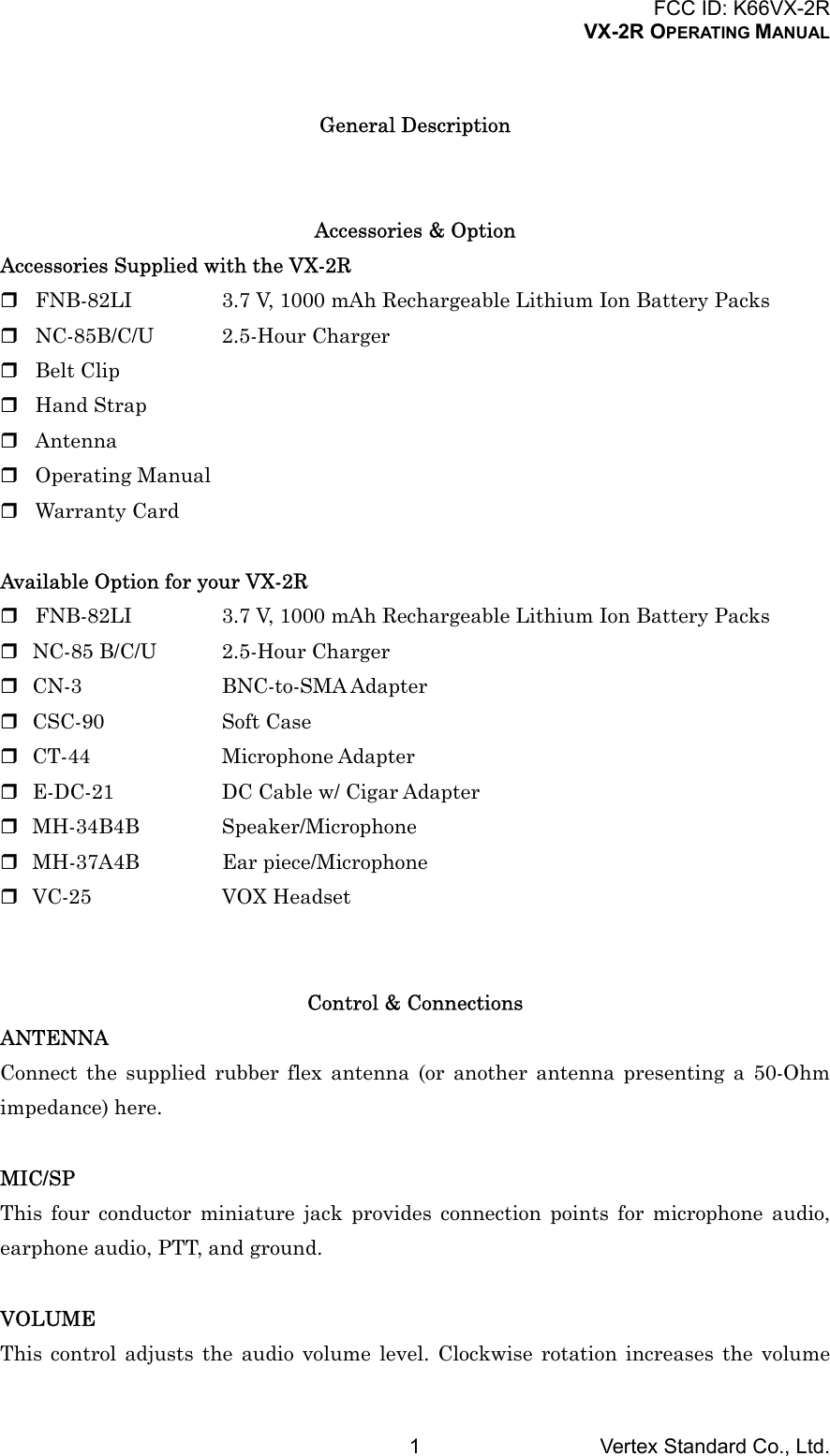
![FCC ID: K66VX-2RVX-2R OPERATING MANUALVertex Standard Co., Ltd.3Keypad FunctionsKey Press Key Press + [FW] Key Press and hold KeyBAND Moves operation to thenext-highest frequencyband.Moves operation to thenext-lowest frequencyband.Activates the Scanner.H/L Switches the transmitpower output between“HI” and “LOW.”Select the synthesizersteps to be used duringVFO operation.Enter the “Set” (Menu)mode.V/M Switches frequencycontrol between theVFO and MemorySystem.Activates the “MemoryTune” mode while inthe Memory Recallmode.Activates the DualWatch feature.FW Activates the“Alternate” keyfunction.Disables the“Alternate” keyfunction.Activates the “MemoryWrite” mode (formemory channelstorage).HM/RV Reverse the transmitand receive frequencieswhile working througha repeater.Switches operation tothe “Home” (favoritefrequency) channel.Activates theEmergency Function.% Activate the WIRESTM(Internet Connection)feature.Recall the “Weather”broadcast channelsand Short-wavebroadcast stationchannels.Activates the ARTSfeature.MD Switches the operatingmode.Activates the CTCSSor DCS operation.Activate the SmartSearch feature.Installation of AccessoriesAntenna InstallationThe supplied antenna provides good results over the entire frequency range of thetransceiver. However, for enhanced base station medium-wave and shortwave reception,you may wish to connect an external (outside) antenna.To install the supplied antennaHold the bottom end of the antenna, then screw it onto the mating connector on thetransceiver until it is snug. Do not over-tighten by use of extreme force.Notes: Never transmit without having an antenna connected. When installing the supplied antenna, never hold the upper part of the antennawhile screwing it onto the mating connector on the transceiver.](https://usermanual.wiki/Yaesu-Musen/VX-2R/User-Guide-317850-Page-3.png)
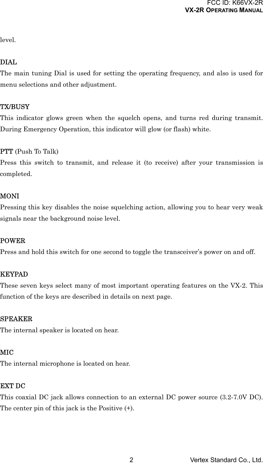
![FCC ID: K66VX-2RVX-2R OPERATING MANUALVertex Standard Co., Ltd.5OperationR. F. says: Hi! I’m R. F. Radio, and I’ll be helping you along as you learn the manyfeatures of the VX-2R. I know you’re anxious to get on the air, but I encourage you toread the “Operation” section of this manual as thoroughly as possible, so you’ll get themost out of this fantastic new transceiver. Now. . .let’s get operating!Switching Power On and Off1. Be sure the Battery Pack is installed, and that the battery is fully charged. Connectthe antenna to the top panel ANTENNA jack.2. Press and hold in the POWER switch (on the left side of the transceiver) for onesecond. Two beeps will be heard when the switch has been held long enough, andthe current DC supply voltage will indicate on the display for 2 second. After thisinterval, the display will resume its normal indication of the operating frequency.3. To turn the VX-2R off, press and hold in the POWER switch again for one second.R.F. says: If you don’t hear the two “Beep” tones when the radio comes on, the Beepermay have been disabled via the Menu system. See page ??, which tells you how toreactivate the Beeper.Adjusting the Volume LevelRotate the VOLUME control (inner knob) to set the desired audio level. Clockwiserotation increases the volume level.Squelch AdjustmentThe VX-2R’s Squelch system allows you to mute the background noise when no signal isbeing received. Not only does the Squelch system make “standby” operation morepleasant, it also significantly reduces battery current consumption.The Squelch system may be adjusted independently for the FM and Wide-FM (FMBroadcast) modes.1. Press and hold the [H/L(STEP)SET] key for one second to enter the Set Mode.2. Rotate the DIAL knob to select the Set Mode Item 1: SQL.3. Press the [H/L] key momentarily to enable adjustment this Item.4. Rotate the DIAL knob to set the background noise is just silenced (typically at asetting of about “1” or “2” for FM, and “2” or “3” for Wide-FM); this is point ofmaximum sensitivity to weak signals.](https://usermanual.wiki/Yaesu-Musen/VX-2R/User-Guide-317850-Page-5.png)
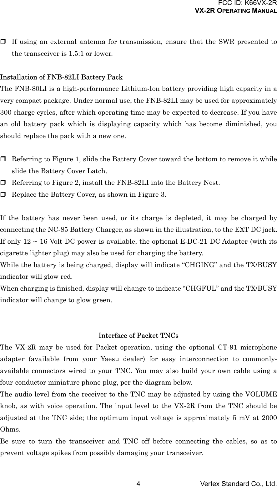
![FCC ID: K66VX-2RVX-2R OPERATING MANUALVertex Standard Co., Ltd.65. When you are satisfied with the Squelch threshold setting, press the PTT keymomentarily to save the new setting and exit to normal operation.R.F. Says: 1) A special “RF Squelch” feature is provided on the VX-2R. This featureallows you to set the squelch so that only signals exceeding a certain S-meter level willopen the squelch. See page ?? for details.2) If you’re operating in an area of high RF pollution, you may need to consider “ToneSquelch” operation using the built-in CTCSS Decoder. This feature will keep your radioquiet until a call is received from a station sending a carrier which contains a matching(subaudible) CTCSS tone. Or if your friends have radios equipped with DCS (DigitalCoded Squelch) like your VX-2R has, try using that mode for silent monitoring of busychannels.Selecting the Operating BandThe VX-2R covers an incredibly wide frequency range, over which a number of differentoperating modes are used. Therefore, the VX-2R’s frequency coverage has been dividedinto different operating bands, each of which has its own pre-set channel steps andoperating modes. You can change the channel steps and operating modes later, if youlike (see page ??).To Change Operating Bands:1. Press the [BAND] key repetitively. You will see the LCD indication move toward ahigher frequency band each time you press the [BAND] key.2. If you wish to move the operating band selection downward (toward lowerfrequencies), press the [F/W] key first, then press the [BAND] key.3. Once you have selected the desired band, you may initiate manual tuning (orscanning) per the discussions on the next chapter.Frequency NavigationThe VX-2R will initially be operating in the “VFO” mode, a channelized system whichallows free tuning throughout the currently-selected operating band.Two basic frequency navigation methods are available on the VX-2R:1) Tuning Dial (Outer ring of dual control on Top Panel)Rotation of the DIAL allows tuning in the pre-programmed steps established for thecurrent operating band. Clockwise rotation of the DIAL causes the VX-2R to be tunedtoward a higher frequency, while counter-clockwise rotation will lower the operating](https://usermanual.wiki/Yaesu-Musen/VX-2R/User-Guide-317850-Page-6.png)
![FCC ID: K66VX-2RVX-2R OPERATING MANUALVertex Standard Co., Ltd.7frequency.If you press the [F/W] key momentarily, then rotate the DIAL, frequency steps of 1 MHzwill be selected. This feature is extremely useful for making rapid frequency excursionsover the wide tuning range of the VX-2R.2) ScanningFrom the VFO mode, press and hold the [BAND] key. The VX-2R will begin scanningtoward a higher frequency, and will stop when it receives a signal strong enough tobreak through the Squelch threshold. The VX-2R will then hold on that frequencyaccording to the setting of the “RESUME” mode (Set Mode Item 28: RESUME). Seepage ?? for details.If you wish to reverse the direction of the scan (i.e. toward a lower frequency, instead ofa higher frequency), just rotate the DIAL one click in the counter-clockwise directionwhile the VX-2R is scanning. The scanning direction will be reversed. To revert toscanning toward a higher frequency once more, rotate the DIAL one click clockwise.Press the PTT switch momentarily to cancel the scanning.TransmissionOnce you have set up an appropriate frequency inside one of the 144 MHz or 430 MHzAmateur bands on which the VX-2R can transmit, you’re ready to transmit. These arethe most basic steps; more advanced aspects of transmitter operation will be discussedlater.1. To transmit, press the PTT switch, and speak into the front panel microphone(located in the upper left-hand corner of the speaker grille) in a normal voice level.The TX/BUSY indicator will glow red during transmission.2. To return to the receive mode, release the PTT switch.3. During transmission, the relative power level will be indicated on the LCD.Additionally, the “L” icon will appear at the bottom of the display while operatingon the “Low Power” Level setting.R.F. Says: If you’re just talking to friends in the immediate area, you’ll get much longerbattery life by switching to Low Power operation. To do this, press the [H/L] key so thatthe “L” icon appears at the bottom of the display. And don’t forget: always have anantenna connected when you transmit.Transmission is possible only on the 144 MHz and 430 MHz bands.R.F. Says: 1) The VX-2R is smart! You can set up Low power on 144 MHz band, while](https://usermanual.wiki/Yaesu-Musen/VX-2R/User-Guide-317850-Page-7.png)
![FCC ID: K66VX-2RVX-2R OPERATING MANUALVertex Standard Co., Ltd.8leaving 430 MHz on High power, and the radio will remember the different settings onboth band. And when you store memories, you can store High and Low power settingsseparately in each memory, so you don’t waste battery power when using very close-inrepeaters!2) When you are operating on one of the Low power settings, you can press the [F/W]key, when press the PTT switch, to cause the VX-2R to transmit (temporarily) on Highpower. After one transmission, the power level will revert to the previously-selected Lowpower setting.Keyboard LockingIn order to prevent accidental frequency change or inadvertent transmission, variousaspects of the VX-2R’s keys and switches may be locked out. The possible lockoutcombinations are:KEY: Just the front panel keys are locked outDIAL: Just the top panel DIAL is locked outK + D: Both the DIAL and Keys are locked outPTT: The PTT switch is locked (TX not possible)K + P: Both the keys and PTT switch are locked outD + P: Both the DIAL and PTT switch are locked outALL: All of the above are locked outTo lock out some or all of the keys:1. Press and hold the [H/L] key for one second to enter the Set mode.2. Rotate the DIAL knob to select the Set Mode Item 9: LOCK.3. Press the [H/L] key momentarily to enable adjustment this Item.4. Rotate the DIAL knob to choose between one of the locking schemes as outlinedabove.5. When you have made your selection, press the PTT key to save the new setting andreturn to normal operation.To activate the locking feature, press the [F/W] key, then press and hold the [BAND]key for one second. The “Key Lock” icon will appear on the LCD. To cancel locking, againabove procedures.Keypad/LCD IlluminationYour VX-2R includes a reddish illumination lamp which aids in nighttime operation.](https://usermanual.wiki/Yaesu-Musen/VX-2R/User-Guide-317850-Page-8.png)
![FCC ID: K66VX-2RVX-2R OPERATING MANUALVertex Standard Co., Ltd.9The red illumination yields clear viewing of the display in a dark environment, withminimal degradation of your night vision. Three options for activating the lamp areprovided:KEY Mode: Illuminates the Keypad/LCD for five seconds when any key pressed.CONT Mode: Illuminates the Keypad/LCD continuously.OFF Mode: Disables the Keypad/LCD lamp.Here is the procedure for setting up the Lamp mode:1. Press and hold the [H/L] key for one second to enter the Set mode.2. Rotate the DIAL knob to select the Set Mode Item 17: LAMP.3. Press the [H/L] key momentarily to enable adjustment this Item.4. Rotate the DIAL knob to select one of the three modes described above.5. When you have made your choice, press the PTT key to save the new setting andreturn to normal operation.R.F. Says: You may adjust the Keypad/LCD illumination level and LCD contrast by theSet Mode. See page ?? for details.Disabling the Keypad BeeperIf the keypad’s Beeper creates an inconvenience (particularly when operating in a quietroom), it may easily be disabled.1. Press and hold the [H/L] key for one second to enter the Set mode.2. Rotate the DIAL knob to select the Set Mode Item 8: BEEP.3. Press the [H/L] key momentarily to enable adjustment this Item.4. Rotate the DIAL knob to change the setting from ON to OFF.5. When you have made your selection, press the PTT key to save the new setting andreturn to normal operation.6. If you wish to re-enable the Beeper, just repeat the above procedure, rotate theDIAL knob to select ON in step “4” above.Advanced OperationNow that you’re mastered the basics of VX-2R operation, let’s learn more about some ofthe really neat features.Changing the Channel StepsThe VX-2R’s synthesizer provides the option of utilizing channel steps of](https://usermanual.wiki/Yaesu-Musen/VX-2R/User-Guide-317850-Page-9.png)
![FCC ID: K66VX-2RVX-2R OPERATING MANUALVertex Standard Co., Ltd.105/9/10/12.5/15/20/25/50/100 kHz per step, any number of which may be important toyour operating requirements. The VX-2R is set up at the factory with different defaultsteps on each operating band which probably are satisfactory for most operation.However, if you need to change the channel step increments, the procedure to do so isvery easy.1. Press and hold the [H/L] key for one second to enter the Set mode.2. Rotate the DIAL knob to select the Set Mode Item 3: STEP.3. Press the [H/L] key momentarily to enable adjustment this Item.4. Rotate the DIAL knob to select the new channel step size.5. When you have made your selection, press the PTT key to save the new setting andreturn to normal operation.R.F. Says: 9 kHz step is available on the BC band only.Changing the Operating ModeThe VX-2R provides for automatic mode changing when the radio is tuned to differentoperating frequencies. However, should an unusual operating situation arise in whichyou need to change between the available operating modes (FM-Narrow, FM-Wide, andAM), here is the procedure for doing so:1. Press and hold the [H/L] key for one second to enter the Set mode.2. Rotate the DIAL knob to select the Set Mode Item 4: RX MD.3. Press the [H/L] key momentarily to enable adjustment this Item.4. Rotate the DIAL knob to select the new operating mode. The available selectionsare:AUTO: Automatic mode setting per default values for the selected frequency range.N-FM: Narrow-bandwidth FM (used for voice communication)W-FM: Wide-bandwidth FM (used for high-fidelity broadcasting)AM: Amplitude Modulation5. When you have made your selection, press the PTT key to save the new setting andreturn to normal operation.R.F. Says: Unless you have a compelling reason to do so, leave the Automatic ModeSelection feature on so as to save time and trouble when changing bands. If you make amode change for a particular channel or station, you can always store that one channelinto memory, as the mode setting will be memorized along with the frequencyinformation.](https://usermanual.wiki/Yaesu-Musen/VX-2R/User-Guide-317850-Page-10.png)
![FCC ID: K66VX-2RVX-2R OPERATING MANUALVertex Standard Co., Ltd.11Repeater OperationRepeater stations, usually located on mountaintops or other high locations, provide adramatic extension of the communication range for low-powered hand-held or mobiletransceivers. The VX-2R includes a number of features which make repeater operationsimple and enjoyable.Repeater ShiftsYour VX-2R has been configured, at the factory, for the repeater shifts customary inyour country. For the 144 MHz band shift will be 600 kHz; on the 430 MHz band, theshift may be 1.6 MHz, 7.6 MHz, or 5 MHz (USA version).Depending on the part of the band in which you are operating, the repeater shift may beeither downward (–) or upward (+), and one of these icons will appear at the bottom ofthe LCD when repeater shifts have been enabled.Automatic Repeater Shift (ARS)The VX-2R provides a convenient Automatic Repeater Shift feature, which causes theappropriate repeater shift to be automatically applied whenever you tune into thedesignated repeater sub-bands in your country. These sub-bands are shown below.If the ARS feature does not appear to be working, you may have accidentally disabled it.To re-enable ARS:1. Press and hold the [H/L] key for one second to enter the Set mode.2. Rotate the DIAL knob to select the Set Mode Item 5: ARS.3. Press the [H/L] key momentarily to enable adjustment this Item.4. Rotate the DIAL knob to select “ON” (to enable Automatic Repeater Shift).5. When you have made your selection, press the PTT key to save the new setting andreturn to normal operation.Manual Repeater Shift ActivationIf the ARS feature has been disabled, or if you need to set a repeater shift directionother than that established by the ARS, you may set the direction of the repeater shiftmanually.To do this:1. Press and hold the [H/L] key for one second to enter the Set mode.2. Rotate the DIAL knob to select the Set Mode Item 7: RPT.](https://usermanual.wiki/Yaesu-Musen/VX-2R/User-Guide-317850-Page-11.png)
![FCC ID: K66VX-2RVX-2R OPERATING MANUALVertex Standard Co., Ltd.123. Press the [H/L] key momentarily to enable adjustment this Item.4. Rotate the DIAL knob to select the desired shift among “–RPT,” “+RPT,” and“SIMP.”5. When you have made your selection, press the PTT key to save the new setting andreturn to normal operation.Changing the Default Repeater ShiftsIf you travel to a different region, you may need to change the default repeater shift soas to ensure compatibility with local operating requirements.To do this, follow the procedure below:1. Press and hold the [H/L] key for one second to enter the Set mode.2. Rotate the DIAL knob to select the Set Mode Item 6: SHIFT.3. Press the [H/L] key momentarily to enable adjustment this Item.4. Rotate the DIAL knob to select the new repeater shift magnitude.5. When you have made your selection, press the PTT key to save the new setting andreturn to normal operation.R.F. Says: If you just have one “odd” split that you need to program, don’t change the“default” repeated shifts using this Menu Item! Enter the transmit and receivefrequencies separately, as shown on page ??.Checking the Repeater Uplink (Input) FrequencyIt often is helpful to be able to check the uplink (input) frequency of a repeater, to see ifthe calling station is within direct (“Simplex”) range.To do this, just press the [HM/RV] key. You’ll notice that the display has shifted to therepeater uplink frequency. Press the [HM/RV] key again to cause operation to revert tonormal monitoring of the repeater downlink (output) frequency.RF Says: The configuration of this key may be set either to “RV” (for checking the inputfrequency of a repeater, or “HM” (for instant switching to the “Home” channel for theband you are operating on). To change the configuration of this key, use Set Mode Item40: HM/RV. See page ??.CTCSS OperationMany repeater systems require that a very-low-frequency audio tone be superimposedon your FM carrier in order to activate the repeater. This helps prevent false activationof the repeater by radar or spurious signals from other transmitters. This tone system,](https://usermanual.wiki/Yaesu-Musen/VX-2R/User-Guide-317850-Page-12.png)
![FCC ID: K66VX-2RVX-2R OPERATING MANUALVertex Standard Co., Ltd.13called “CTCSS” (Continuous Tone Coded Squelch System), is included in your VX-2R,and is very easy to activate.R.F. Says: CTCSS setup involves two actions: setting the Tone Frequency and thensetting of the Tone Mode. These actions are set up by using the [MD] key or Set ModeItems 18: SQL TYP and 19: TN FRQ.1. Press and hold the [MD] key for one second. This provides a “Short-cut” to Set ModeItem 18: SQL TYP.2. Press the [H/L] key momentarily to enable adjustment this Item.3. Rotate the DIAL knob so that “TONE” appears on the display; this activates theCTCSS Encoder, which allows repeater access.R.F. Says: You may notice an additional “DCS” icon appearing while you rotate theDIAL knob in this step. We’ll discuss the Digital Code Squelch system shortly.4. Rotate the DIAL knob in step “3” above will occasionally appear the “TSQ.” When“TSQ” appears, this means that the Tone SQueLch system is active, which mutesyour VX-2R’s receiver until it receives a call from another radio sending out amatching CTCSS tone. This can help keep your radio quiet until a specific call isreceived, which may be helpful while operating in congested areas.5. When you have made your selection of the CTCSS tone mode, press the [H/L] keymomentarily, then rotate the DIAL one click clockwise to select Set Mode Item 19:TN FRQ. This Menu selection allows setting of the CTCSS tone frequency to beused.6. Press the [H/L] key momentarily to enable the adjustment of the CTCSS frequency.7. Rotate the DIAL knob until the display indicates the Tone Frequency you need to beusing (ask the repeater owner/operator if you don’t know the tone frequency).8. When you have made your selection, press the [H/L] key momentarily, then pressthe PTT switch to save the new settings and exit to normal operation.R.F. Says: Your repeater may or may not re-transmit a CTCSS tone - some systems justuse CTCSS to control access to the repeater, but don’t pass it along when transmitting.If the S-Meter deflects, but the VX-2R is not passing audio, repeat steps “1” through “4”above, but rotate the DIAL so that “TSQ” disappears - this will allow you to hear alltraffic on the channel being received.DCS OperationAnother form of tone access control is Digital Code Squelch, or DCS. It is a newer, moreadvanced tone system which generally provides more immunity from false paging thandoes CTCSS. The DCS Encoder/Decoder is built into your VX-2R, and operation is very](https://usermanual.wiki/Yaesu-Musen/VX-2R/User-Guide-317850-Page-13.png)
![FCC ID: K66VX-2RVX-2R OPERATING MANUALVertex Standard Co., Ltd.14similar to that just described for CTCSS. Your repeater system may be configured forDCS; if not, it is frequently quite useful in Simplex operation if your friend(s) usetransceivers equipped with this advanced feature.R.F. Says: Just as in CTCSS operation, DCS requires that you set the Tone Mode to DCSand that you select a tone code.1. Press and hold the [MD] key for one second. This provides a “Short-cut” to Set ModeItem 18: SQL TY2. Press the [H/L] key momentarily to enable adjustment this Item.3. Rotate the DIAL knob until “DCS” appears on the display; this activates the DCSEncoder/Decoder.4. Press the [H/L] key momentarily, then rotate the DIAL to select Set Mode Item 20:DCS CD).5. Press the [H/L] key momentarily to enable the adjustment of the DCS code.6. Rotate the DIAL knob to select the desired DCS Code (a three-digit number). Askthe repeater owner/operator if you don’t know DCS Code; if you are workingsimplex, just set up the DCS Code to be the same as that used by your friend(s).7. When you have made your selection, press the [H/L] key momentarily,, then pressthe PTT switch to save the new settings and exit to normal operation.R.F. Says: Remember that the DCS is an Encode/Decode system, so your receiver willremain muted until a matching DCS code is received on an incoming transmission.Switch the DCS off when you’re just tuning around the band!Tone Search ScanningIn operating situations where you don’t know the CTCSS or DCS tone being used byanother station or stations, you can command the radio to listen to the incoming signaland scan in search of the tone being used. Two things must be remembered in thisregard: You must be sure that your repeater uses the same tone type (CTCSS vs. DCS). Some repeaters do not pass the CTCSS tone; you may have to listen to the station(s)transmitting on the repeater uplink (input) frequency in order to allow Tone SearchScanning to work.To scan for the tone in use:1. Set the radio up for either CTCSS or DCS Decoder operation (see the previousdiscussion). In the case of CTCSS, “TSQ” will appear on the display; in the case of](https://usermanual.wiki/Yaesu-Musen/VX-2R/User-Guide-317850-Page-14.png)
![FCC ID: K66VX-2RVX-2R OPERATING MANUALVertex Standard Co., Ltd.15DCS, “DCS” will appear on the display.2. Press and hold the [H/L] key for one second to enter the Set mode.3. Rotate the DIAL knob to select the Set Mode Item 19: TN FRQ when TONE SQL isselected, or Set Mode Item 20 DCS CD during DCS operation.4. Press the [H/L] key momentarily to enable adjustment of the selected Menu Item.5. Press and hold the [BAND] key for one second to start scanning for the incomingCTCSS or DCS tone/code.6. When the radio detects the correct tone or code, it will halt on that tone/code, andaudio will be allowed to pass. Press the [BAND] key to lock in that tone/code, thenpress PTT to exit to normal operation.R.F. Says: If the Tone Scan feature does not detect a tone or code, it will continue to scanindefinitely. When this happens, it may be that the other station is not sending any tone.You can press the PTT switch to halt the scan at any time.You also can press the MONI key during Tone Scanning to listen to the (muted) signalfrom the other station. When you release the MONI key, Tone Scanning will resumeafter about a second.Tone Scanning works either in the VFO or Memory modes.CTCSS/DCS Bell OperationDuring CTCSS Decode or DCS operation, you may set up the VX-2R such that a ringing“bell” sound alerts you to the fact that a call is coming in. Here is the procedure foractivating the CTCSS/DCS Bell:1. Set the transceiver up for CTCSS Decode (“Tone Squelch”) or DCS operation, asdescribed previously.2. Adjust the operating frequency to the desired channel.3. Press and hold the [H/L] key for one second to enter the Set mode.4. Rotate the DIAL knob to select the Set Mode Item 22: BELL.5. Press the [H/L] key momentarily to enable adjustment of the selected Menu Item.6. Rotate the DIAL knob to set the desired number of rings of the Bell. The availablechoices are 1, 3, 5, or 8 rings, CONT (continuous ringing), or OFF.7. Press the PTT key momentarily to save the new setting and exit to normaloperation.When you are called by a station whose transceiver is sending a CTCSS tone or DCScode which matches that set into your Decoder, the Bell will ring in accordance to this](https://usermanual.wiki/Yaesu-Musen/VX-2R/User-Guide-317850-Page-15.png)
![FCC ID: K66VX-2RVX-2R OPERATING MANUALVertex Standard Co., Ltd.16programming.Split Tone OperationThe VX-2R can be operated in a Split Tone configuration via the Set mode.1. Press and hold the [H/L] key for one second to enter the Set mode.2. Rotate the DIAL knob to select the Set Mode Item 23: SPLIT.3. Press the [H/L] key momentarily to enable adjustment of the selected Menu Item.4. Rotate the DIAL knob to select ON (to enable the Split Tone feature).5. Press the PTT key momentarily to save the new setting and exit to normaloperation.When the Split Tone feature is activated, you can see the following additionalparameters after the “DCS” parameter while selecting the Set Mode Item 18: SQL TYP:D CODE: DCS Encode onlyT DCS: Encodes a CTCSS Tone and Decodes a DCS codeD TONE: Encodes a DCS code and Decodes a CTCSS ToneSelect the desired operating mode from the selections shown above.Tone Calling (1750 Hz)If the repeaters in your country require a 1750-Hz burst tone for access (typically inEurope), you can set the MONI key to serve as a “Tone Call” switch instead. To changethe configuration of this switch, we again use the Menu to help us.1. Press and hold the [H/L] key for one second to enter the Set mode.2. Rotate the DIAL knob to select the Set Mode Item 41: M/T-CL.3. Press the [H/L] key momentarily to enable adjustment of the selected Menu Item.4. Rotate the DIAL knob to select “T-CALL” on the display.5. Press the PTT key to save the new setting and exit to normal operation.To access a repeater, press and hold in the MONI key for the amount of time specified bythe repeater owner/operator. The transmitter will automatically be activated, and a1750-Hz audio tone will be superimposed on the carrier. Once access to the repeater hasbeen gained, you may release the MONI key, and use the PTT key for activating thetransmitter.ARTS (Automatic Range Transponder System)The ARTS feature uses DCS signaling to inform both parties when you and another](https://usermanual.wiki/Yaesu-Musen/VX-2R/User-Guide-317850-Page-16.png)
![FCC ID: K66VX-2RVX-2R OPERATING MANUALVertex Standard Co., Ltd.17ARTS-equipped station are within communications range. This may be particularlyuseful during Search-and Rescue situations, where is important to stay in contact withother members of your group.Both stations must set up their DCS codes to the same code number, then activate theirARTS feature using the command appropriate for their radio. Alert ringers may beactivated, if desired.Whenever you push the PTT, or every 25 (or 15) seconds after ARTS is activated, yourradio will transmit a signal which includes a (subaudible) DCS signal for about 1 second.If the other radio is in range, the beeper will sound (if enabled) and the display willshow “IN RNG” as opposed to the out of range display “OUT RNG” in which ARTSoperation begins.Whether you talk or not, the polling every 15 or 25 seconds will continue until you de-activate ARTS. Every 10 minutes, moreover, you can have your radio transmit yourcallsign via CW, so as to comply with identification requirements. When ARTS is de-activated, DCS will also be deactivated (if you were not using it previously in non-ARTSoperation).If you move out of range for more than one minute (four pollings), your radio will sensethat no signal has been received, three beeps will sound, and the display will revert to“OUT RNG.” If you move back into range, your radio will again beep, and the displaywill change back to the “IN RNG” indication.During ARTS operation, your operating frequency will continue to be displayed, but nochanges may be made to it or other settings; you must terminate ARTS in order toresume normal operation. This is a safety feature designed to prevent accidental loss ofcontact due to channel change, etc.Basic ARTS Setup and Operation1. Set your radio and the other radio(s) to the same DCS code number, per thediscussion on page ??.2. Press and hold the [%] key for one second. You will observe the “OUT RNG” displayon the LCD below the operating frequency. ARTS operation has now commenced.3. Every 25 seconds, your radio will transmit a “polling” call to the other station.When that station responds with its own ARTS polling signal, the display willchange to “IN RNG” to confirm that the other station’s polling code was received inresponse to yours.4. Press and hold the [%] key for one second to exit ARTS operation and resumenormal functioning of the transceiver.](https://usermanual.wiki/Yaesu-Musen/VX-2R/User-Guide-317850-Page-17.png)
![FCC ID: K66VX-2RVX-2R OPERATING MANUALVertex Standard Co., Ltd.18R.F. Says: ARTS won’t work if you have used the Lock feature to disable the PTT!ARTS Polling Time OptionsThe ARTS feature may be programmed to poll every 25 seconds (default value) or 15seconds. The default value provides maximum battery conservation, because the pollingsignal is sent out less frequently. To change the polling interval:1. Press and hold the [H/L] key for one second to enter the Set mode.2. Rotate the DIAL knob to select the Set Mode Item 38: AR INT.3. Press the [H/L] key momentarily to enable adjustment of the selected Menu Item.4. Rotate the DIAL knob to select the desired polling interval (15 or 25 seconds).5. When you have made your selection, press the PTT key to save the new setting andexit to normal operation.ARTS Alert Beep OptionsThe ARTS feature allows two kinds of alert beeps (with the additional option of turningthem off), so as to alert you to the current status of ARTS operation. Depending on yourlocation and the potential annoyance associated with frequent beeps, you may choosethe Beep mode which best suits your needs. The choices are:IN RNG: The beeps are issued only when the radio first confirms that you are withinrange, but does not re-confirm with beeps thereafter.ALWAYS: Every time a polling transmission is received from the other station, the alertbeeps will be heard.OFF: No alert beeps will be heard; you must look at the display to confirm currentARTS status.To set the ARTS Beep mode, use the following procedure:1. Press and hold the [H/L] key for one second to enter the Set mode.2. Rotate the DIAL knob to select the Set Mode Item 37: ARTSBP.3. Press the [H/L] key momentarily to enable adjustment of the selected Menu Item.4. Rotate the DIAL knob to select the desired ARTS Beep mode (see above).5. When you have made your selection, press the PTT key to save the new setting andexit to normal operation.CW Identifier SetupThe ARTS feature includes a CW identifier, as discussed previously. Every ten minutesduring ARTS operation, the radio can be instructed to send “DE (your callsign) K” if this](https://usermanual.wiki/Yaesu-Musen/VX-2R/User-Guide-317850-Page-18.png)
![FCC ID: K66VX-2RVX-2R OPERATING MANUALVertex Standard Co., Ltd.19feature is enabled. The callsign field may contain up to 16 characters.Here’s how to program the CW Identifier:1. Press and hold the [H/L] key for one second to enter the Set mode.2. Rotate the DIAL knob to select the Set Mode Item 39: CW ID.3. Press the [H/L] key momentarily to enable adjustment of the selected Menu Item.4. Rotate the DIAL knob to select ON (to enable the CW ID function).5. Press the [MH/RV] key momentarily to clear any previous callsign.6. Rotate the DIAL knob to select the first letter/number of your callsign, then pressthe [V/M] key momentarily to save the first letter/number and move on to the nextcharacter.7. Repeat the previous step as necessary to complete your callsign. Note that the“slant bar” (– • • – •) is among the available characters, should you be a “portable”station.8. If you mistake, press the [BAND] key to back-space the cursor, re-enter the correctletter/number.9. Press the [HM/RV] key to delete all data after the cursor that may have beenpreviously stored erroneously.10. When you have entered your entire callsign, press the [H/L] key momentarily toconfirm the callsign, then press the PTT key to save the settings and exit to normaloperation.R.F. Says: You may check your work by monitoring the entered callsign. To do this,repeat steps 1- 3 above, then press the [MON/F] key.DTMF OperationDespite the lack of a DTMF keypad, you can still transmit DTMF tones with the VX-2Rfor repeater control or autopatch use.Manual DTMF Tone GenerationDTMF AutodialerNine DTMF Autodial memories are provided, allowing you to store telephone numbersfor autopatch use. You can also store short autopatch or Internet-link access codestreams so as to avoid having to send them manually.Here is the DTMF Autodial storage procedure:](https://usermanual.wiki/Yaesu-Musen/VX-2R/User-Guide-317850-Page-19.png)
![FCC ID: K66VX-2RVX-2R OPERATING MANUALVertex Standard Co., Ltd.201. Press and hold the [H/L] key for one second to enter the Set mode.2. Rotate the DIAL knob to select the Set Mode Item 24: DTMF.3. Press the [H/L] key to enable adjustment of this Menu Item.4. Rotate the DIAL knob to select the DTMF Memory register into which you wish tostore this DTMF string.5. Press the [H/L] key momentarily, then rotate the DIAL knob one click clockwise toselect the Set Mode Item 25: DTMF S.6. Press the [H/L] key to begin DTMF Memory entry into the selected register. Thefirst digit blinks.7. Rotate the DIAL knob to select the first digit of the DTMF string. Selectable entriesare 1 - 9, and A - F, with E and F representing DTMF “*” and “#” tones respectively.8. Press the [V/M] key momentarily to accept the first digit and move to the seconddigit of the DTMF string.9. Repeat the previous steps until you have completed the telephone number string.10. Press the [H/L] key momentarily to store the DTMF memory.11. To store another number, rotate the DIAL knob to select another DTMF Memoryregister, and repeat this procedures.12. When finished storing DTMF Memories, press the PTT switch to return to normaldisplay.To send the telephone number:1. Press and hold the [H/L] key for one second to enter the Set mode.2. Rotate the DIAL to select the Set Mode Item 24: DTMF.3. Press the [H/L] key to enable adjustment of this Menu Item.4. Rotate the DIAL knob to select the DTMF Memory register (DTMF 1 throughDTMF 9) you wish to send.5. Press the PTT switch to exit to normal operation and activate the DTMF Autodialerfunction (the “Telephone” icon will appear).6. In the Autodialer function mode, while still holding the PTT switch in, press the[H/L] key momentarily to transmit the tone string. Once the string begins, you mayrelease the PTT key, as the transmitter will be held “on the air” until the DTMFstring is completed.Emergency Channel OperationThe VX-2R includes an “Emergency” feature which may be useful if you have someonemonitoring on the same frequency as your transceiver’s UHF “Home” channel. See](https://usermanual.wiki/Yaesu-Musen/VX-2R/User-Guide-317850-Page-20.png)
![FCC ID: K66VX-2RVX-2R OPERATING MANUALVertex Standard Co., Ltd.21page ?? for details on setting the Home channel.The “Emergency” feature is activated by press and holding the [HM/RV] key for onesecond.When this is done, (A) the radio is placed on the UHF amateur band Home channel, (B)it emits a loud “Alarm” sound (the volume is controlled by the VOL knob), (C) it flashesthe TX/BUSY indicator in white, (D) if you press the PTT key, you will disable theEmergency feature temporarily; you can then transmit on the UHF Home channel, and(E) two seconds after the PTT release, the Emergency feature will resume.To disable the “Emergency” feature, press and hold the [HM/RV] key for one second orturn the radio Off by pressing and holding in the [PWR] switch for one second.Use this feature if you are out for a walk and want a quick way of alerting a familymember as to a dangerous situation. The alarm sound may discourage an attacker andallow you to escape.R.F. Says: 1) Be sure to arrange with a friend or family member to be monitoring on thesame frequency, as there will be no identification sent via the Emergency alarm sound.And do not transmit the alarm tone except in a true emergency!2) The TX/BUSY indicator may be changed to another function via Set Mode Item 42:EMG S; see page xx.](https://usermanual.wiki/Yaesu-Musen/VX-2R/User-Guide-317850-Page-21.png)