Yaesu Musen VX-3200U UHF Mobile Transceiver User Manual Operating Manual
Yaesu Musen Co., Ltd. UHF Mobile Transceiver Operating Manual
UserManual.wiki
>
Yaesu Musen
>
VX 3200U User Manual
Operating Manual
Navigation menu
Upload a User Manual
Namespaces
Wiki Guide
HTML
PDF
Info
Views
User Manual
Discussion / Help
Navigation

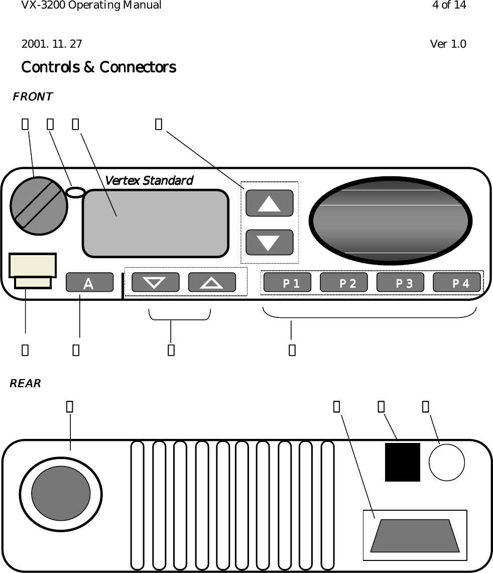
![VX-3200 Operating Manual 5 of 142001. 11. 27 Ver 1.0Important!Important!Important!Important! – All buttons located on the Front Panel are Programmable Function Button (PFProgrammable Function Button (PFProgrammable Function Button (PFProgrammable Function Button (PFbutton) button) button) button) determined by your network requirements and programmed by your VERTEXSTANDARD dealer. Following instruction is along with nominal button programming.①①①①VOL. / PWR KnobVOL. / PWR KnobVOL. / PWR KnobVOL. / PWR KnobRotate the knob to turn the transceiver ON and OFF and set the volume of thereceiver.②②②②Busy / Busy / Busy / Busy / TXTXTXTX Indicator Indicator Indicator IndicatorThis lamp glows red when the radio is transmitting and glows green when thechannel is busy.Steady Green : Busy ChannelBlinking Green : Tone Squelch in defeated conditionSteady Red : Transmission in Progress③③③③LCD (Liquid Crystal Display)LCD (Liquid Crystal Display)LCD (Liquid Crystal Display)LCD (Liquid Crystal Display)The display include an 8-character alpha-numeric section showing Group andChannel names, status and identity information, and error messages. Additionalindicators on the display show priority channel assignments and scan include /exclude selection.④④④④▲▲▲▲・▼ ・▼ ・▼ ・▼ Button [Programmable Function Button ]Button [Programmable Function Button ]Button [Programmable Function Button ]Button [Programmable Function Button ]Pressing these buttons changes the current Channel (and displayed Channel numberor name). Holding this button for more than 1/2 second causes the function to repeat.⑤⑤⑤⑤Microphone JackMicrophone JackMicrophone JackMicrophone JackConnect the microphone plug to this jack.⑥⑥⑥⑥A Button [Programmable Function Button ]A Button [Programmable Function Button ]A Button [Programmable Function Button ]A Button [Programmable Function Button ]This button can be set up for special applications, such as high/low power selection,monitor, Talk-around, etc, as determined by your network requirements andprogrammed by your VERTEX STANDARD dealer.⑦⑦⑦⑦▽▽▽▽・△ ・△ ・△ ・△ Button [Programmable Function Button ]Button [Programmable Function Button ]Button [Programmable Function Button ]Button [Programmable Function Button ]Pressing these buttons changes the current Group (and displayed Channel number orname). Holding this button for more than 1/2 second causes the function to repeat.⑧⑧⑧⑧P1 to P4 [Programmable Function Button ]P1 to P4 [Programmable Function Button ]P1 to P4 [Programmable Function Button ]P1 to P4 [Programmable Function Button ]This button can be set up for special applications, such as High/Low power selection,Monitor, Talk-around, etc, as determined by your network requirements andprogrammed by your VERTEX STANDARD dealer.⑨⑨⑨⑨Antenna SocketAntenna SocketAntenna SocketAntenna SocketThe 50-ohm coaxial feedline to the antenna must be connected here, using a type-M(PL-259) plug.⑩⑩⑩⑩D-Sub 9Pin Accessory ConnectorD-Sub 9Pin Accessory ConnectorD-Sub 9Pin Accessory ConnectorD-Sub 9Pin Accessory Connector](https://usermanual.wiki/Yaesu-Musen/VX-3200U/User-Guide-191349-Page-5.png)