Yaesu Musen VX-3200V VHF Transceiver User Manual C Manual VX 3200 VX 3200 p65
Yaesu Musen Co., Ltd. VHF Transceiver C Manual VX 3200 VX 3200 p65
UserManual.wiki
>
Yaesu Musen
>
VX 3200V User Manual
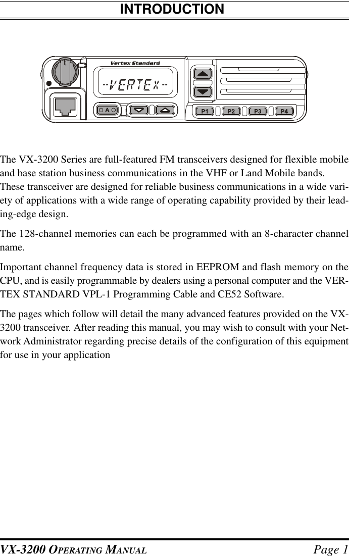
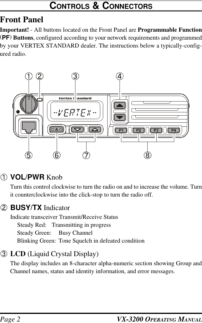
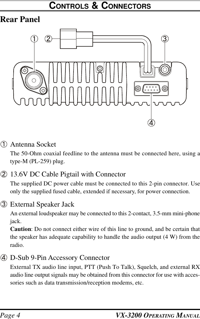
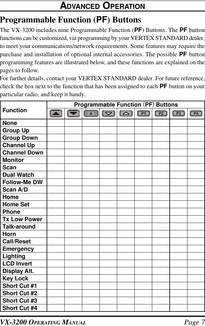
Operating Manual
Navigation menu
Upload a User Manual
Namespaces
Wiki Guide
HTML
PDF
Info
Views
User Manual
Discussion / Help
Navigation
![VX-3200 OPERATING MANUAL Page 3[q]/[p] Buttons (Programmable Function Buttons)Pressing either button changes the current channel (and displayed channel num-ber or name). Holding a button for more than 1/2 second causes the function torepeat.Microphone JackConnect the microphone plug to this jack.[A] Button (Programmable Function Button)This button can be set up for special applications, such as High/Low power se-lection, Monitor, Talk-Around, etc, as determined by your network requirementsand programmed by your VERTEX STANDARD dealer.[s]/[r] Buttons (Programmable Function Buttons)Pressing either button changes the current group (and displayed group numberor name). Holding a button for more than 1/2 second causes the function torepeat.[P1] - [P4] Buttons (Programmable Function Buttons)These buttons can be set up for special applications, such as High/Low powerselection, Monitor, Talk-Around, etc, as determined by your network require-ments and programmed by your VERTEX STANDARD dealer.CONTROLS & CONNECTORSCurrent Group on “Scan” ListLCD Icons & Indicators8-Character Alpha-Numeric DisplayTransmission in progress,(follows Red BUSY/TX in-dicator).Busy Channel (followsGreen BUSY/TX indicator). Talk-Around EnabledLow TX PowerHorn Function Activate:Home System/Group:Priority Group](https://usermanual.wiki/Yaesu-Musen/VX-3200V/User-Guide-250836-Page-5.png)
![VX-3200 OPERATING MANUAL Page 5BASIC OPERATION OF THE TRANSCEIVERImportant! - Before turning on the radio the first time, confirm that the power con-nections have been made correctly and that a proper antenna is connected to theantenna jack.Switching Power ON/OFFrTurn the VOL/PWR knob turn on the radio. The display will become illumi-nated.rPress the [q]/[p] button to choose the desired operating channel. A channelname will appear on the display. If you want to select an operating channel froma different group, press the [s]/[r] button to select the group you want beforeselecting the operating channel.Setting the VolumerTurn the VOL/PWR knob clockwise to increase the volume, and counterclock-wise to decrease it.TransmittingrTo transmit, monitor the channel and make sure it is clear.THIS IS AN FCC REQUIRMENT!Press the PF button which is programmed to the Monitor feature to listen forchannel activity.rWhen receiving a call, transmit only after the incoming call ends. The radio can-not receive a call and transmit simultaneously.rPress the PTT switch.rIf the channel is clear, the BUSY/TX indicator will glow red. The radio is nowtransmitting. While holding in the PTT switch, speak across the face of the mi-crophone in a clear and normal voice. For best transmission, hold the microphoneabout 1-1/2 to 2 inches away from your mouth. Release the PTT switch to re-ceive.rIf the Busy Channel Lockout feature has been programmed on a channel, theradio will not transmit when a carrier is present. Instead, the radio will generate acontinuous low-pitched tone while the PTT switch is pressed. Release the PTTswitch and wait for the channel to be clear of activity.rIf CTCSS or Digital Coded Squelch (DCS) Lockout has been programmed on achannel, the radio can transmit only when there is no carrier being received orwhen the carrier being received includes the correct CTCSS tone or DCS code.](https://usermanual.wiki/Yaesu-Musen/VX-3200V/User-Guide-250836-Page-7.png)
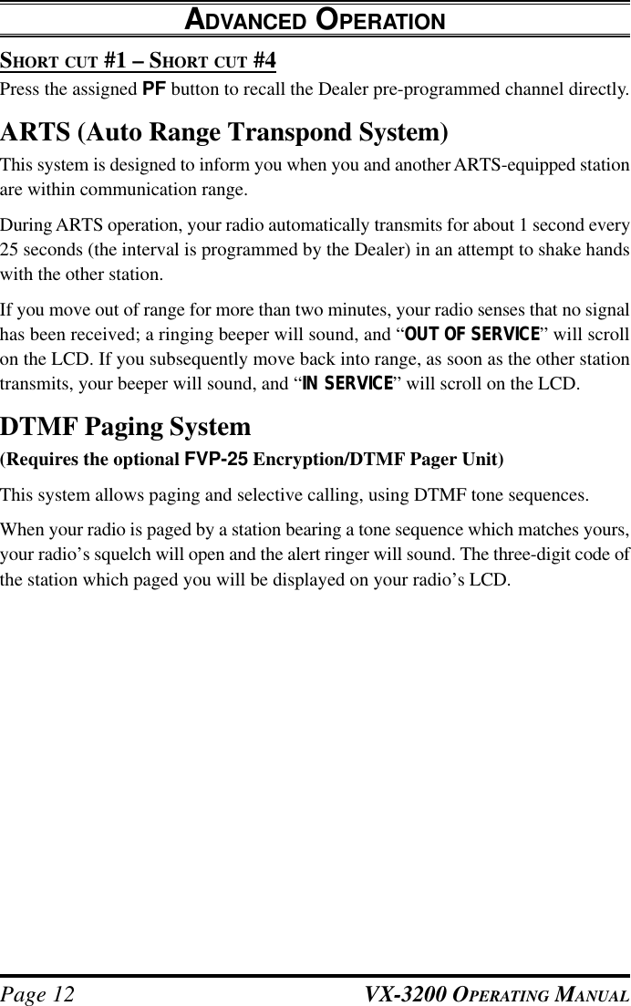
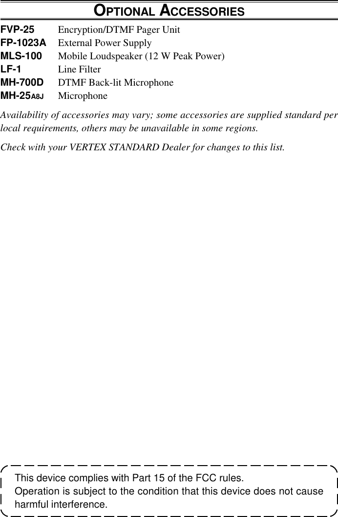
![VX-3200 OPERATING MANUALPage 8Description of Operating FunctionsGROUP UP/GROUP DOWN (GROUP SELECTION)The VX-3200 is capable of separating its 128 memory channels into any of 10 groups.There is no limit as to the number of channels which may be assigned to each group.The Dealer will have made the group assignment at the time of channel program-ming.rPress the assigned PF button (generally the [s]/[r] button) to change the group.Once the desired group is reached, press the PF button which is assigned to theChannel Up/Channel Down feature (generally the [q]/[p] button) to select thedesired channel within the selected group.CHANNEL UP/CHANNEL DOWN (CHANNEL SELECTION)Press the assigned PF button (generally the [q]/[p] button) to select a differentchannel within the current group.MONITORPress the assigned PF button momentarily to cancel CTCSS- and DCS-controlledsquelch; the BUSY/TX indicator will blink green. Press and hold this button for 1.5seconds to hear background noise (unmute the audio); the BUSY/TX indicator willglow green.ADVANCED OPERATION](https://usermanual.wiki/Yaesu-Musen/VX-3200V/User-Guide-250836-Page-10.png)
![VX-3200 OPERATING MANUALPage 10FOLLOW-ME DWTo set up a “Dual Watch” frequency pair using the “Follow-Me” feature, select achannel using the assigned PF button (generally the [q]/[p] button). Now press theassigned PF button; pressing the assigned PF button locks the current channel as theUser-assigned Priority Channel, and “ ” icon will appear on the LCD.HOMErPress the assigned PF button to recall the pre-programmed Home group/channel.When you recall the Home group/channel, the “ ” icon will appear on the LCD.rPress this button again to return to previous group/channel; the “ ” icon willdisappear on the LCD.HOME SETPress and hold the assigned PF button to store the current group/channel to the Homeregister.PHONEPress the assigned PF button to dial the Dealer pre-programmed Auto-Dial tele-phone number. The DTMF tones sent during the dialing sequence will be heard in thespeaker.TX LOW POWERPress the assigned PF button to set the radio’s transmitter to the “Low Power” mode.Press this button again to return to “High Power” operation when in difficult terrain.TALK AROUNDPress the assigned PF button to activate the Talk Around feature when you are oper-ating on duplex channel systems (separate receive and transmit frequencies, utilizinga “repeater” station). The Talk Around feature allows you to bypass the repeaterstation and talk directly to a station that is nearby. This feature has no effect when youare operating on “Simplex” channels, where the receive and transmit frequencies arealready the same.Note that your dealer may have made provision for “Talk Around” channels by pro-gramming “repeater” and “Talk Around” frequencies on two adjacent channels. If so,the key may be used for one of the other Pre-Programmed Functions.ADVANCED OPERATION](https://usermanual.wiki/Yaesu-Musen/VX-3200V/User-Guide-250836-Page-12.png)