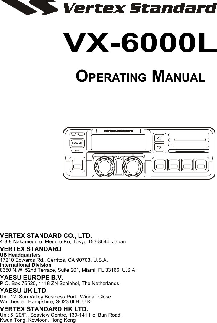
Yaesu Musen VX-6000L Low VHF Transceiver User Manual VX 6000 Operating Manual

Yaesu Musen Co., Ltd. Low VHF Transceiver VX 6000 Operating Manual

Operating Manual

VX-6000LOPERATING MANUALVERTEX STANDARD CO., LTD.4-8-8 Nakameguro, Meguro-Ku, Tokyo 153-8644, JapanVERTEX STANDARDUS Headquarters17210 Edwards Rd., Cerritos, CA 90703, U.S.A.International Division8350 N.W. 52nd Terrace, Suite 201, Miami, FL 33166, U.S.A.YAESU EUROPE B.V.P.O. Box 75525, 1118 ZN Schiphol, The NetherlandsYAESU UK LTD.Unit 12, Sun Valley Business Park, Winnall CloseWinchester, Hampshire, SO23 0LB, U.K.VERTEX STANDARD HK LTD.Unit 5, 20/F., Seaview Centre, 139-141 Hoi Bun Road,Kwun Tong, Kowloon, Hong KongPOWER
Congratulations!You now have at your fingertips a valuable communications tool - a two-way radio! Rugged, reliable and easy to use, your   radio willkeep you in constant touch with your colleagues for years to come, with negligible main-tenance down time.Please take a few minutes to read this manual carefully. The information presented herewill allow you to derive maximum performance from your radio. After reading it, keepthe manual handy for quick reference, in case questions arise later on.We’re glad you joined the   team. Call on us any time, because ourbusiness is communications. Let us help you get your message across.NOTICEThere are no user-serviceable points inside this transceiver.  All service jobs mustbe referred to your Authorized Service Center or Network Administrator.Safety / Warning InformationWARNING - DO NOT operate the VX-6000L radio when someone (bystanders)outside the vehicle is within following range.Safety Training information:Antennas used for this transmitter must not exceed an antenna gain of 0 dB.  Theradio must be used in vehicle-mount configurations with a maximum operating dutyfactor not exceeding 50%, in typical Push-to-Talk configurations.This radio is restricted to occupational use, work related operations only where theradio operator must have the knowledge to control the exposure conditions of itspassengers and bystanders by maintaining the minimum separation distance offollowing range.Failure to observe these restrictions will result in exceeding the FCC RF exposurelimits.Antenna Installation:For rear deck trunk installation, the antenna must be located at least following rangeaway from rear seat passengers in order to comply with the FCC RF exposurerequirements.For roof top installation, the antenna must be placed in the center of the roof.Radiated frequency and DistanceVX-6000L1.55 m
Page 1VX-6000 Operating ManualVX-6000 Operating ManualThe VX-6000L is full-featured FM transceivers designed for flexible mobile and basestation business communications in the VHF Low-Band (120/50 Watts: programmable)Land Mobile Bands. Each model is designed for reliable business communications in awide variety of applications, with a wide range of operating capability provided by itsleading-edge design.The 250-channels memories can each be programmed with a 8-character channel name.Important channel frequency data is stored in EEPROM and flash memory on the CPU,and is easily programmable by dealers using a personal computer and the VERTEX STAN-DARD CT-71 Programming Cable and CE35 Software.The pages which follow will detail the many advanced features provided on the VX-6000L transceiver. After reading this manual, you may wish to consult with your NetworkAdministrator regarding precise details of the configuration of this equipment for use inyour application.POWER
Page 2 VX-6000 Operating ManualCONTROLS & CONNECTORSFront Panel1POWER BottonPress the button to turn the transceiver ON and OFF.2TX IndicatorThis lamp glows red when the radio is transmitting.3BUSY IndicatorThis lamp glows green when the channel is busy.4Liquid Crystal DisplayThe display include an 8-character alpha-numeric section showing channel and groupnames, status and identity information, and error messages. Additional indicators onthe display show priority channel assignments and scan include / exclude selection.8 Character Alpha-numeric Invertible DisplayChannel Group NumberThis channel on “INTERCOM” ListThis channel on “SELECTABLE TONE” ListThis channel on “SCAN” ListReceiver MonitorThis channel on “PUBLIC ADDRESS” or“CHANNEL RECALL”  ListThis channel on “HORN ALERT” ListThis channel on“OPTION” ListThis channel on “AUX A/B/C” ListPOWER!"#$%&'()*
Page 3VX-6000 Operating Manual5!!!!!/""""" ButtonPressing these buttons changes the current group (and displayed group number orname). Holding this button for more than 1/2 second causes the function to repeat.6SQC IndicatorThis lamp glows orange when incorrect position at the setting of CE35.7Programmable Function Button (PF button)This button can be set up for special applications, such as high/low power selection,monitor, dimmer, talk-around, and call alert function, as determined by your networkrequirements and programmed by your VERTEX STANDARD dealer.8VOLUME KnobThis knob sets the volume of the receiver.9EMERGENCY MicrophoneThe emergency microphone is located behind this small slit. When the emergencyfeature is activated, this Microphone is enabled.10 CHANNEL Selector KnobThis knob select the operating channel.11 Programmable Function Button (PF button)This button can be set up for special applications, such as high/low power selection,monitor, dimmer, talk-around, and call alert function, as determined by your networkrequirements and programmed by your VERTEX STANDARD dealer.Side PanelMicrophone Jack (It is on both sides.)Connect the microphone plug to this jack.CONTROLS & CONNECTORSMicrophone Jack
Page 4 VX-6000 Operating ManualREAR (Heatsink)1Antenna SocketThe 50-ohm coaxial feedline to the antenna must be connected here, using a type-M(PL-259) plug.2External Speaker JackAn external loudspeaker may be connected to this 2-contact, 3.5-mm mini-phonejack.Caution: Do not connect this line to ground, and be certain that the speaker hasadequate capability to handle the audio output from the VX-6000.313.6-V DC Power ConnectorThe supplied DC power cable must be connected to this 4-pin connector. Use onlythe supplied fused cable, extended if necessary, for power connection.4DSUB 25-Pin Accessory ConnectorExternal TX audio line input, PTT (Push To Talk), Squelch, and external RX audioline output signal may be obtained from this connector for use with accessories suchas data transmission/reception modems, ets.CONTROLS & CONNECTORS!"*#
Page 5VX-6000 Operating ManualBASIC OPERATION OF THE TRANSCEIVERImportant! - Before turning on the radio the first time, confirm that the power connec-tions have been made correctly and that a proper antenna is connected to the antenna jack.Switching Power ON/OFFPush the POWER switch turn on the radio. The display will become illuminated. Theradio will start up on the last channel used prior to shut-down during the previousoperating session.Turn the CHANNEL selector knob to choose the desired operating channel. A chan-nel name will appear on the display. If you want to select the operating channel from adifferent Memory Channel Group, press the UP (!) or DOWN (") button to selectthe Memory Channel Group you want before selecting the operating channel.Setting the VolumeTurn the VOLUME knob clockwise to increase the volume, and counterclockwise todecrease it. If no signal is present, press and hold in the MON button more than 1/2seconds; background noise will now be heard, and you may use this to set the VOL-UME knob for the desired audio level. Press and hold the MON button more than 1/2seconds to quiet the noise and resume normal (quiet) monitoring.TransmittingTo transmit, wait until the “BUSY” indicator is off (the channel is not in use), andpress the PTT (Push-To-Talk) switch on the side of the microphone (the “TX” indica-tor will appear or the “TX” indicator will glow red). While holding in the PTT switch,speak across the face of the microphone in a clear, normal voice level, and then releasethe PTT switch to receive.Selecting Groups and Channelsm Press the UP (!) or DOWN (") button (repeatedly, if necessary) to select a differ-ent group of channels.m Turn the CHANNEL selector knob to select a different channel within the currentgroup.Automatic Time-Out TimerIf the selected channel has been programmed for automatic time-out, you must limitthe length of each transmission. While transmitting, a beep will sound five secondsbefore time-out. Another beep will sound just before the deadline; the “TX” indicatorwill disappear and transmission will cease soon thereafter. To resume transmitting,you must release the PTT and wait for the “penalty timer” to expire (if you press thePTT before this timer expires, the timer restarts, and you will have to wait another“penalty” period)
Page 6 VX-6000 Operating ManualPOWERADVANCED OPERATIONProgrammable Function Button (PF button)The VX-6000L includes the seven Programmable Function Buttons (PF button).The PF button functions can be customized, via programming by your VERTEX STAN-DARD dealer, to meet your communications/network requirements. Some features mayrequire the purchase and installation of opetional internal accessories. The possible PFbutton programming features are illustrated at the below, and their functions are explainedon page 8.For further details, contact your VERTEX STANDARD dealer. For future reference, checkthe box next to each function that has been assigned to the PF button on your particularradio, and keep it handy.Functions Programmable Function Button (PF button)NoneSCAN (SCN)Dual WatchCall/ResetTalk-Around (TA)Noise Blanker* (NB)Alpha Numeric (A/N)DIMMER (DIM)Emergency (EMG)Horn Alert (HA)Home Channel (HOM)Intercom (IC)Low Power (LOW)GRP UPGRP DWNCH UPCH DWNAUX AAUX BAUX CMonitor (MON)<1.5 sec >1.5 sec <1.5 sec >1.5 sec <1.5 sec >1.5 sec <1.5 sec >1.5 sec <1.5 sec >1.5 sec <1.5 sec >1.5 sec <1.5 sec >1.5 sec
Page 7VX-6000 Operating ManualADVANCED OPERATIONFunctions Programmable Function Button (PF button)Public Address (PA)RCLSelectable Tone (ST)SP**Squlch Level (SQL)CompanderEncryption*** (OPT)* for VX-6000L ** requires RMK-4000 *** requires Encryption UnitChannel ScanThe Scanning feature is used to monitor multiple signals programmed into the trans-ceiver. While scanning, the transceiver will check each channel for the presence of asignal, and will stop on a channel if a signal is present.To activate scanning:mPress the assigned PF button of the “Scan” momentarily to activate scanning.mThe scanner will search the channels, looking for active ones; it will pause eachtime it finds a channel on which someone is speaking.To stop scanningmPress the assigned PF button of the “Scan”.mOperation will revert to the channel to which the CHANNEL selector knob is set.Note: Your dealer may have programmed your radio to stay on one of the followingchannels if you press the PTT switch during scanning pause:rCurrent channel (“Talk Back”) r “Last Busy” channelr“Priority” channel r “Home” channelr“Scan Start” channelDual WatchThe Dual Watch feature is similar to the Scan feature, except that only two channelsare monitored:rThe current operating channel; andrThe “Priority” channel.To activate Dual Watch:mPress the assigned PF button of the “Dual Watch”.mThe scanner will search the two channels; it will pause each time it finds a channelon which someone is speaking.To stop Dual Watch:mPress the assigned PF button of the “Dual Watch”.mOperation will revert to the channel to which the CHANNEL selector knob is set.<1.5 sec >1.5 sec <1.5 sec >1.5 sec <1.5 sec >1.5 sec <1.5 sec >1.5 sec <1.5 sec >1.5 sec <1.5 sec >1.5 sec <1.5 sec >1.5 sec
Page 8 VX-6000 Operating ManualARTS (Auto Range Transpond System)This system is designed to inform you when you and another ARTS-equipped station arewithin communication range.During ARTS operation, your radio automatically transmits for about 1 second every 25(or 55) seconds (the interval is programmed by Dealer) in an attempt to Shake hands withthe other station.If you move out of range for more than one minutes, your radio senses that no signal hasbeen received, a ringing beeper will sound. If you subsequently move back into range, assoon as the other station transmits, your beeper will sound.The PF Button FunctionThe PF (Programmable Function) button can be programmed by the dealer to providetwo of the other functions described below.To activate the primary Accessory function, press the PF button momentarily. To accessthe secondary Accessory function (which may include the Alarm), press and hold the PFbutton for 1.5 seconds or longer.Call/ResetWhen this feature is programmed and a selective call has been received, momen-tarily press the assigned PF button of the “Call/Reset” to reset the flashing indicatorand mute the receiver, otherwise press the assigned PF button of the “Call/Reset” tosent your radio’s identification code (ANI) to the dispatcher.Talk-AroundThe feature causes the assigned PF button of the “Talk-Around” to select simplexoperation on semi-duplex channels: the transmit frequency becomes the same as thereceive frequency (regardless of any programmed offset for the channel).Note:This feature has no effect on simplex channels. After pressing the button, “TA”is displayed on the LCD.Noise Blanker (for VX-6000L)Because local noise can be particularly troublesome in the VHF Low-Band frequencyspectrum, the Low-Band version of the VX-6000 includes a Noise Blanker feature,which may be toggled on and off by pressing the assigned PF button of the “NoiseBlanker” for the appropriate length of time.Alpha NumericPress the assigned PF button of the “Alpha Numeric” to switch the display betweenthe Group/Channel number, and the Group/Channel name (alphanumeric). A tonewill sound each time you switch between numerical and alphanumerical display.ADVANCED OPERATION
Page 9VX-6000 Operating ManualDIMPress the assigned PF button of the “DIM” to adjust the brightness of the display andkey backright.EMG (Emergency)Press the assigned PF button of the “EMG” to initiate an emergency call (requiresANI board). When an emergency call is made, not tone is emitted and the displaydoes not change. To end the emergency call, turn the transceiver power OFF.HA (Horn Alert)Press the assigned PF button of the “HA” to turn the Horn Alert function ON orOFF. If you receive a call from the base station with 2Tone or DTMF signaling, hornalert will activate.When you turn Horn Alert ON, a tone will sound and “   ” appears on the display.Home (Home Channel)Press the assigned PF button of the “Home” to select the pre-programmed HomeChannel. Press it again to return to the previous channel. If used while scanning,pressing this key a second time will change to the revert channel.IC (Intercom)This feature requires dual head configuration. Press the assigned PF button of the“IC” to turn the intercom feature ON or OFF. While ON, you can press the PTTswitch to communicate to another control head operator without transmitting overthe air. When you press this key, a tone sounds and “ ” appears on the display. Theintercom can be used even while scanning and receiving a callLow PowerPress the assigned PF button of the “Low Power” to set the radio's transmitter to the“Low Power” mode.Press this key again to return to “High Power” operation when in difficult terrain.GRP UP/DWNPress the assigned PF button of the “GRP UP” or “GRP DWN” to select a differentgroup of channels.CH UP/DWNPress the assigned PF button of the “CH UP” or “CH DWN” to select a differentchannel within the current group.AUX A/B/CPress the assigned PF button of the “AUX A”, “AUX B”, or “AUX C” to turn theoutput port (respectively).ADVANCED OPERATION
Page 10 VX-6000 Operating ManualMONI (Monitor)Press the assigned PF button of the “MONI” momentarily to cancel CTCSS andDCS signaling squelch; the “MON” icon appears on the display. Press and hold thiskey for 1/2 seconds to hear background noise (unmute the audio); the MON iconblinks on the display.PA (Public Address)Press the assigned PF button of the “PA” to use the transceiver as a PA amplifier.When you enable this function, a tone sounds and “ ” appears on the display.The public address can be used even while scanning and receiving a call.RCL (Channel Recall)During scan, you can press the assigned PF button of the “RCL” to select the lastcalled channel.ST (Selectable Tone)Press the assigned PF button of the “Selectable Tone”, then rotate the CHANNELselector knob to select a 2-Tone.SPPress the assigned PF button of the “SP” to switch “Front panel”, “Front panel &Body” and “Body” speaker. When “Body” is selected, a tone sounds and the “ ”icon appears on the display. You can use this function while scanning and receivinga call. However, all audio will be emitted from the PA speaker.SQL (Squelch Level)You can manually adjust the squelch level using this function:1. Press the assigned PF button of the “SQL”. A tone sounds and SQL appears onthe display with the current squelch level.2. Rotate the CHANNEL selector knob to select the desired level.3. Press the this key. A tone sounds and the display returns to the normal channel.COMP (Compander)Press the PF button assigned to the “COMP” function to turn the “Compander” ICON or OFF.This IC contains two variable gain circuits configured for compressing and expand-ing the dynamic range of the radio's transmitted audio signal.When you enable this function, the signal-to-noise radio can be improved by reduc-ing the transmitted audio dynamic range.Encryption (Option)When the Voice Scrambler feature is enabled, pressing the assigned PF button of the“Encryption” toggles the Scrambler on and off.ADVANCED OPERATION
Page 11VX-6000 Operating ManualOPTIONAL ACCESSORIESMH-25B7A MicrophoneMH-53C7A Heavy Duty MicrophoneMH-53A7A Heavy Duty Microphone w/Noise CancelerMH-53B7A Heavy Duty DTMF Microphone w/Noise CancelerCE35 Programming SoftwareCT-70 Radio Programming Cable (Requires VPL-1)CT-71 Radio to PC Programming CableCT-72 Radio to Radio Programming CableCT-81 Cable for RMK-4000 (6 m)CT-82 Cable for RMK-4000 (2.5 m)CT-83 Cable for RMK-4000 (0.6 m)CNT-4000 Control HeadRF DECK RF Deck w/MMB-75 (for Dual Band Installations)RMK-4000SH Remote Kit (for Single Transceiver)RMK-4000DH Remote Kit (for Dual-Head Installations)RMK-4000DB Remote Kit (for Dual Band Installations)RMK-4000DBH Remote Kit (for Dual Band plus Dual Head Installations)F2D-8 2-Tone Decode Unit (Requires FIF-7)F5D-14 5-Tone ENC-DEC Unit (Requires FIF-7)VTP-50 VX-Trunk Unit (Requires FIF-7)FVP-25 Encryption/DTMF pager Unit (Requires FIF-7)FP-1023 External 23A Power SupplyMLS-100 Mobile Loud speaker (12 W Peak Power)MMB-75 Mobile Mounting BracketMMB-76 Locking Mobile Mounting BracketLF-1 Line FilterFIF-7 Inter face Board (for F2D-8, F5D-14, VTP-50, FVP-25)CN-6 Inter face Board (for Accessories)
Page 12 VX-6000 Operating ManualNote:
This device complies with Part 15 of the FCC rules.Operation is subject to the condition that this devicedoes not cause harmful interference.
0112?-0YCopyright 2001VERTEX STANDARD CO., LTD.All rights reservedNo portion of this manualmay be reproduced withoutthe permission ofVERTEX STANDARD CO., LTD.Printed in Japan.EC024U750

Navigation menu