Yaesu Musen VX-900U-2 VX-900U / VX-600U User Manual 2001105 REV1 VX 900U VX 600U
Yaesu Musen Co., Ltd. VX-900U / VX-600U 2001105 REV1 VX 900U VX 600U
UserManual.wiki
>
Yaesu Musen
>
VX 900U 2 User Manual
Manual
Navigation menu
Upload a User Manual
Namespaces
Wiki Guide
HTML
PDF
Info
Views
User Manual
Discussion / Help
Navigation
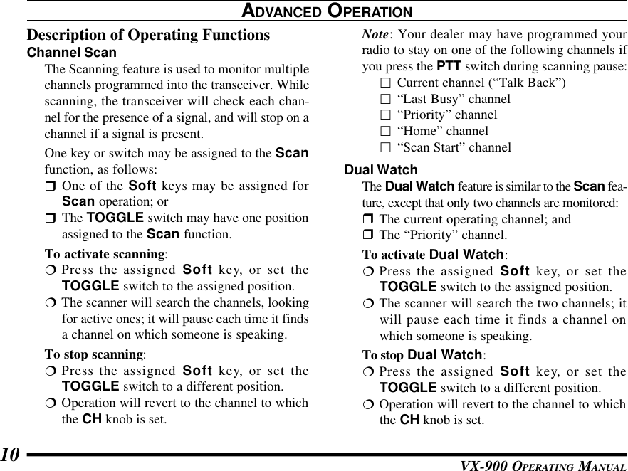
![VX-900 OPERATING MANUAL6rRotate the VOL/PWRknob to set the volumelevel. If no signal ispresent, press and holdin the MONITOR but-ton (under the PTTswitch) more than 2seconds; backgroundnoise will now beheard, and you mayuse this to set theVOL/PWR knob forthe desired audio level.Press and hold theMONITOR button more than 2 seconds (or pressthe MONITOR button twice) to quiet the noiseand resume normal (quiet) monitoring.rTo transmit, press andhold the PTT switch.Speak into the micro-phone area of the frontpanel grille (above the[D] key) in a normalvoice level. To returnto the Receive mode, release the PTT switch.OPERATIONrPress the Soft key (if assigned to the Scan func-tion) or switch the TOGGLE Switch to the as-signed “Scan” position (when so programmed byyour dealer) to start the scanner. The scanner rap-idly steps through each of the dealer-programmedchannels, looking for incoming calls.rPress the TOP SELkey (on the top panel)or SIDE SEL key (thetop button on the leftside) to activate one ofthe preprogrammedfunctions which mayhave been enabled atthe time of program-ming by the dealer.Similarly, when usingthe 16-key version, the[A], [B], [C], and [D]function keys may ac-tivate one of these features, if programmed bythe dealer. See the next section for details regard-ing the available features.](https://usermanual.wiki/Yaesu-Musen/VX-900U-2/User-Guide-150097-Page-9.png)
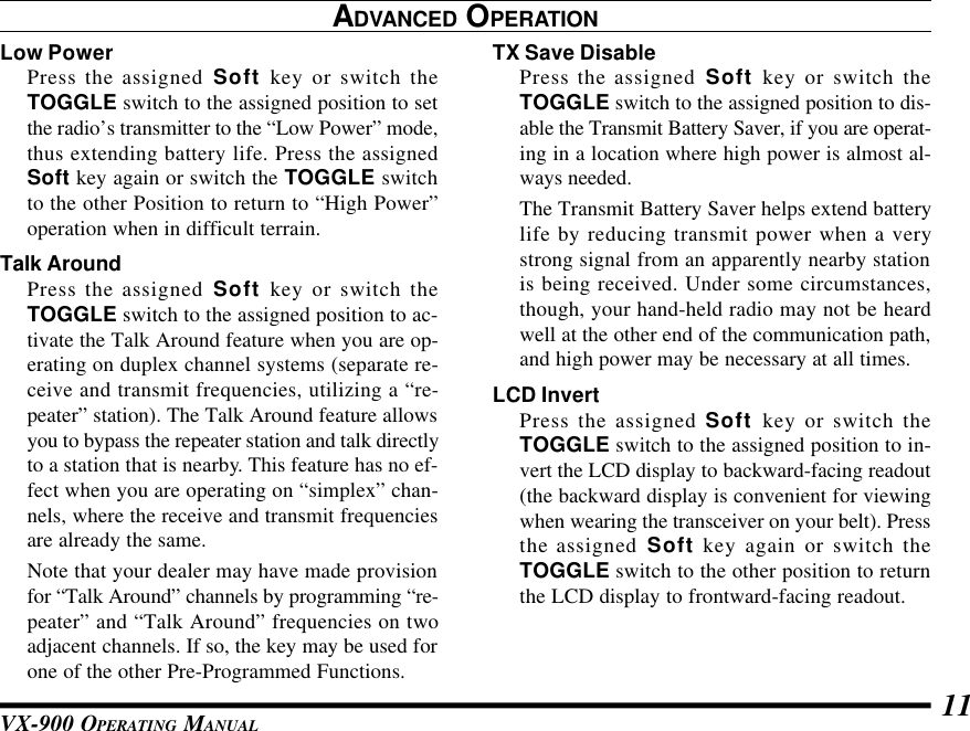
![VX-900 OPERATING MANUAL 7OPERATIONrSwitch the top panel’sTOGGLE switch tothe [A], [B], or [Cen-ter] position to activateone of the pre-pro-grammed functionswhich may have beenenabled at the time of programming by the dealer.When this switch is in the [A (left)], [B (right)],or [Center] position, the feature programmed (byyour dealer) to that switch position will be acti-vated. See the next section for details regardingthe available features.rPress the DTMF keys on the telephone keypadwhile pressing the PTT switch to send DTMFtones (16-key version only).rIf a Speaker/Microphone is available, remove theplastic cap and its two mounting screws from theright side of the transceiver, then align the con-nector of the Speaker/Microphone on the trans-ceiver body; secure the connector pin using thescrews supplied with the Speaker/Microphone.Hold the speaker grille up next to your ear whilereceiving. To transmit, press the PTT switch onthe Speaker/Microphone, just as you would onthe main transceiver’s body, and speak into themicrophone on a normal voice level.Note: Save the original plastic cap and itsmounting screws. They should be reinstalledwhen not using the Speaker/Microphone.](https://usermanual.wiki/Yaesu-Musen/VX-900U-2/User-Guide-150097-Page-10.png)
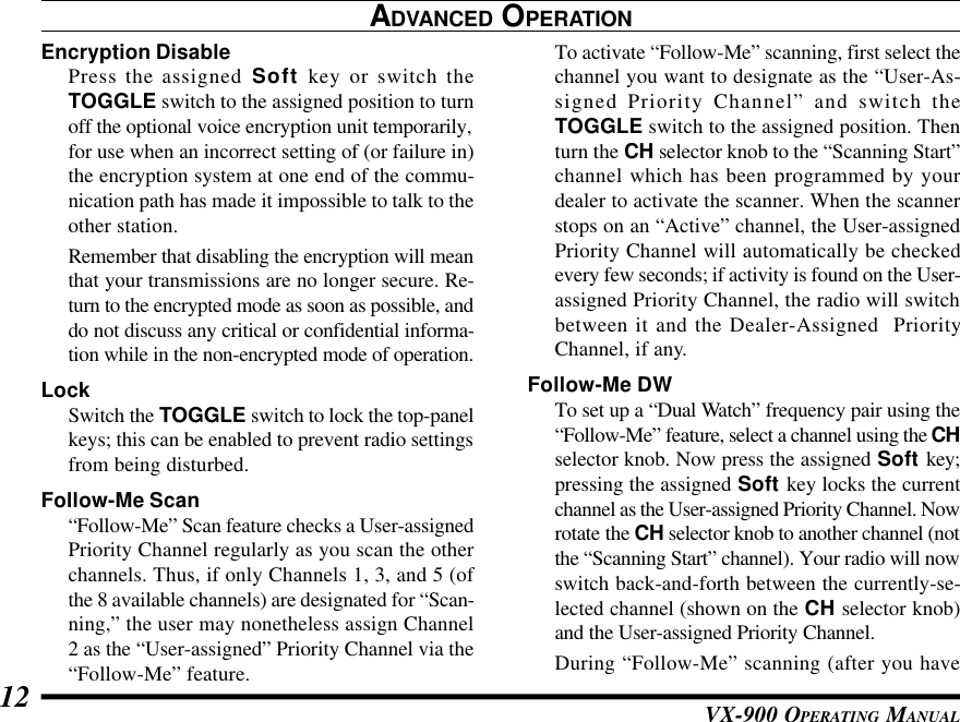
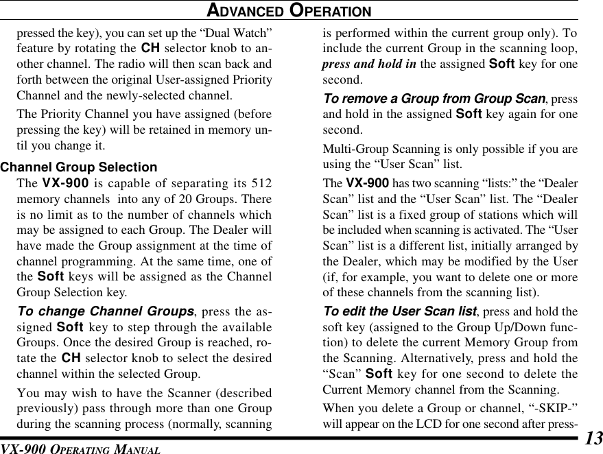
![VX-900 OPERATING MANUAL8ADVANCED OPERATIONSoft key and TOGGLE switch FunctionsThe VX-900 includes the [TOP SEL], [SIDE SEL],[MONITOR], and [LAMP] keys, and the TOGGLEswitch, while the 16-key version additionally pro-vides [A], [B], [C], [D] function keys. The Soft keyand TOGGLE switch functions can be customized,via programming by your VERTEX STANDARDdealer, to meet your communications/network re-quirements. Some features may require the purchaseand installation of optional internal accessories. Thepossible Soft key and TOGGLE switch program-ming features are illustrated at the right, and theirfunctions are explained on page 10. For further de-tails, contact your VERTEX STANDARD dealer.For future reference, check the box next to each func-tion that has been assigned to the Soft key andTOGGLE switch on your particular radio, and keepit handy.ø: Requires FVP-25 DTMF/Encryption UnitTOGGLE switch (Position)A BNoneChannel ScanDual WatchHigh/Low PowerTalk AroundTX Save DisableLCD InvertEncryption DisableøLockFollow-Me ScanGroup Recall ShortcutFunctions center£ Group 1£ Group 2£ Group 3£ Group 1£ Group 2£ Group 3£ Group 1£ Group 2£ Group 3](https://usermanual.wiki/Yaesu-Musen/VX-900U-2/User-Guide-150097-Page-11.png)
![VX-900 OPERATING MANUAL 9ADVANCED OPERATIONNoneChannel ScanDual WatchHigh/Low PowerTalk AroundTX Save DisableLCD InvertEncryption DisableøFollow-Me DWCall/ResetøSpeed DialEmergencyGroup UpGroup DownChannel UpChannel DownMonitorLampø: Requires FVP-25 DTMF/Encryption UnitFunctionsTOP SELSoft keySIDE SEL MONITOR LAMP[A] [B] [C] [D]](https://usermanual.wiki/Yaesu-Musen/VX-900U-2/User-Guide-150097-Page-12.png)