Yaesu Musen VXA-120 Air Band Transceiver User Manual
Yaesu Musen Co., Ltd. Air Band Transceiver
users manual

VXA-120 AVIATOR PROII OPERATING MANUAL 1
INTRODUCTION
The Yaesu VXA-120
Aviator Pro
II is compact, stylish, solid hand-held transceiver providing communica-
tion (transmit and receive) capability on the International Aircraft Communication Band (“COMCOM
COMCOM
COM” band: 118 ~
136.975 MHz), additionally provides receive on the “NAVNAV
NAVNAV
NAV” band (108 ~ 117.975 MHz).
The VXA-120 includes our exclusive two-mode display with upright or inverted for easy viewing when on
your belt, NOAA weather band monitoring capability, 8 character Alpha/Numeric Display, 50 Memory Chan-
nels and 100 Book Memory Channels.
We recommend that you read this manual in its entirety, so as to understand the many features of the VXA-120
completely. Keep this manual handy, so you may use it for reference.
VXA-120 AVIATOR PROII OPERATING MANUAL
2
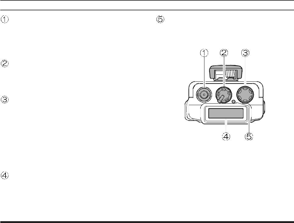
CONTROLS & CONNECTORS (TOP PANEL)
Antenna Jack
This SMA jack accepts thee supplied flexible
antenna, or another antenna designed to provide
50 Ω impedance on the Aircraft Communication
Band.
POWER/VOLUME Knob
Turn this control clockwise to turn the radio on
and to increase the volume. Counterclockwise ro-
tation into the click-stop will turn the radio off.
CHANNEL Selector Knob
This is 20-position detended rotary switch tunes
the operating frequency or selects the memory
channels.
Pressing this knob momentarily selects the tun-
ing methods among VFO (Variable Frequency
Oscillator), MR (Memory Recall), BOOK (Pre-
Programmed Memories), and WX (Weather
Channel Memories) mode.
LCD (Liquid Crystal Display)
The display shows the selected operating condi-
tions as indicated on the next page.
The display may be changed inverted viewing
via the Menu; see page 29 for details.
BUSY/TX Indicator Lamp
This lamp glows green when a signal is being
received and red when transmitting.
VXA-120 AVIATOR PROII OPERATING MANUAL 3
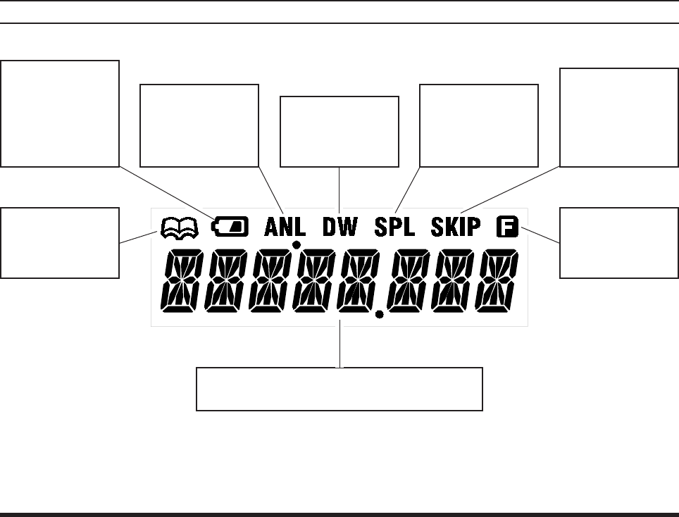
CONTROLS & CONNECTORS (LCD DISPLAY)
This indicator con-
firms that the AUTO-
MATIC NOISE LIMITER
is activated. See
page 17.
This icon is the
“Low Battery” indi-
cator, which blinks
when the battery
voltage becomes
too low for proper
operation.
This indicator con-
firms that DUAL
WATCH is active.
See page 24.
This indicator con-
firms that the
“Split” (Duplex)
mode is activated.
See page 26.
This indicator con-
firms that this
channel will be
skipped during
scan. See page
23.
These digits provide frequency or alphanumeric
information about the channel you are using.
This icon indicates
that the “Book”
Memory Bank is in
use. See page 14.
This indicator con-
firms that
Second-
ary
Key Function is
active. See page 5.
VXA-120 AVIATOR PROII OPERATING MANUAL
4
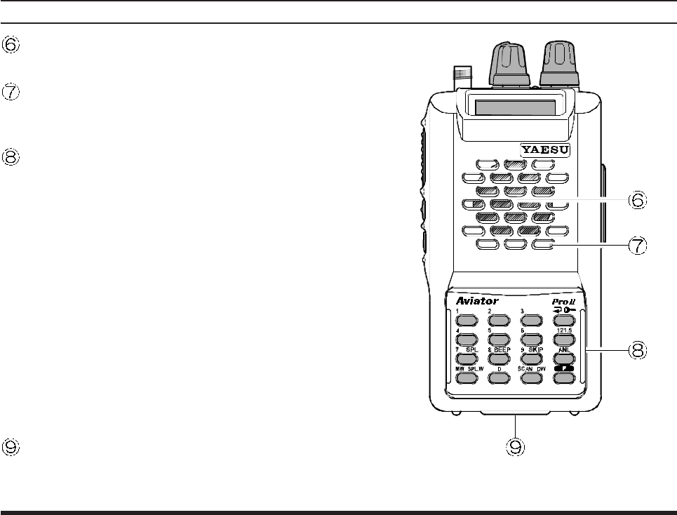
CONTROLS & CONNECTORS (FRONT PANEL)
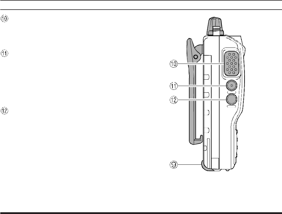
Loudspeaker
The internal speaker located in this position.
Microphone
Speak across this opening in a normal tone voice
while pressing the PTT switch.
Keypad
Several keys have dual functions. The color of
the label determines the way in which you acti-
vate the function:
The white labels represent the primary functions
of the keys (activated by simply pressing the key
momentarily).
The yellow labels represent the secondary func-
tions of the keys (activated by pressing the [F]
key first, then the indicated key).
On the keypad, primary functions (white) are la-
beled to the left, while the secondary functions
(yellow) are labeled to the right. These functions
are described in detail on the next page.
Battery Pack Latch
Open this latch for battery removal.
VXA-120 AVIATOR PROII OPERATING MANUAL 5
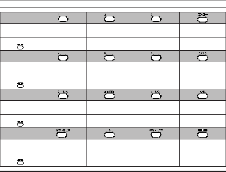
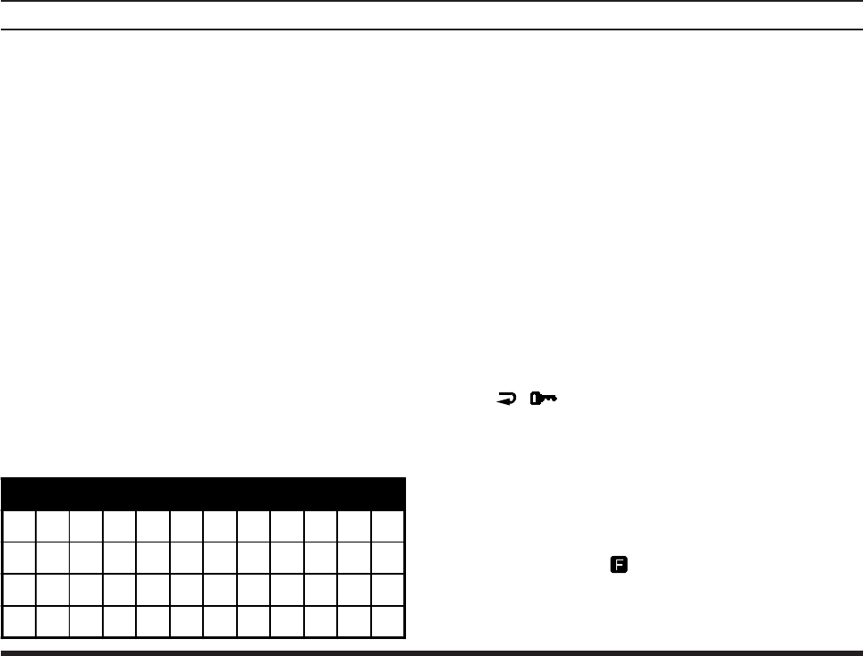
CONTROLS & CONNECTORS (KEYPAD)
Primary Function
(Press Key)
Secondary Function
(Press +)
Primary Function
(Press Key)
Primary Function
(Press Key)
Primary Function
(Press Key)
Frequency Entry
Digit 1 Frequency Entry
Digit 2 Frequency Entry
Digit 3
Frequency Entry
Digit 4 Frequency Entry
Digit 5 Frequency Entry
Digit 6
Frequency Entry
Digit 7 Frequency Entry
Digit 8 Frequency Entry
Digit 9
Frequency Entry
Digit 0
Selects Memory Display
Type (page 19)
Locks the Keypad
Selects Emergency
Channel (121.5 MHz)
None None None
None
NoneNone
Activates Automatic
Noise Limiter
Activates Split (Duplex)
mode On/Off Switch
for Keypad Beeper Allows Skipping of
Channel during Scan
Activates Scanning Activates “Secondary”
Key mode
Activates Dual Watch
Memory “Write”
Command
Split-Memory “Write”
Command
Secondary Function
(Press +)
Secondary Function
(Press +)
Secondary Function
(Press +)
NoneNoneNone
None
VXA-120 AVIATOR PROII OPERATING MANUAL
6
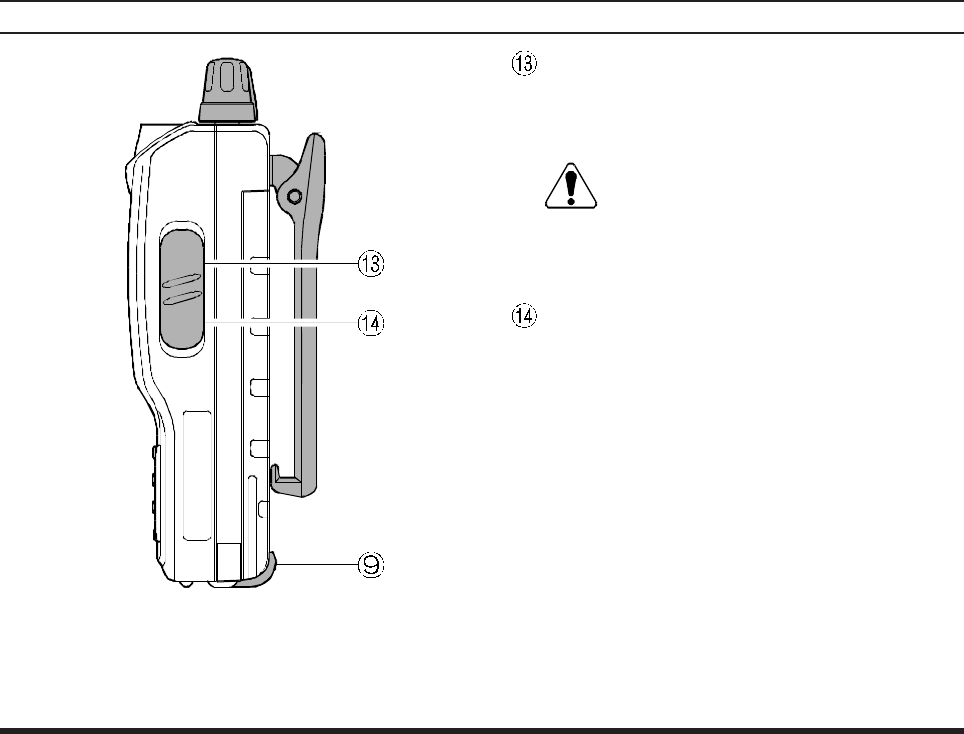
PTT (PUSH TO TALK) Switch
Press this button to transmit when you are oper-
ating in the “COMCOM
COMCOM
COM” band. Release this button to
return to the “RECEIVE” mode. See page 15.
MONITOR Switch
This button may be pressed to “open” the squelch
manually, allowing you to listen for very weak
signals. Press and hold this button for 2 seconds,
to “open” the squelch continuously. Press this
button again to resume normal (quiet) monitor-
ing. See page 12.
LAMP Switch
Press this switch momentarily, to activate the
back-lighting lamp for the display. Press and hold
this switch for 2 seconds, to activate the back-
lighting lamp continuously. To turn the lamp off,
press this switch again. The LAMP switch may
be configured in several ways via the Menu; see
page 28 for details.
CONTROLS & CONNECTORS (LEFT SIDE)
VXA-120 AVIATOR PROII OPERATING MANUAL 7
CONTROLS & CONNECTORS (RIGHT SIDE)
MIC/EAR Jack
You may connect the (optional) CT-60 Headset
Cable or the (optional) MH-44A4B Speaker/Mi-
crophone to this jack.
Never connect the any Speaker/Micro-
phone that is not recommended by the
manufacturer. Because these jack connections are
unique using a Speaker/Microphone that is not
specified by Yaesu will damage the
VXA-120
.
EXT DC Jack
When an external 12-Volt DC power source is
available, you may connect the E-DC-5B Exter-
nal DC Cable here. Do not connect any wire to
this jack if that wire is connected directly to a
28-Volt DC source. Connecting the VXA-120 di-
rectly to a source which exceeds 15.0 Volts DC
will result in damage to the unit.
VXA-120 AVIATOR PROII OPERATING MANUAL
8
BEFORE YOU BEGIN
Precautions
rThis apparatus is capable of two-way communi-
cation on channels used for critical aviation safety
communications. Therefore, it is important that
this radio be kept away from children or other
unauthorized users at all times.
rWhen making DC connections via the E-DC-5B
DC cable, be absolutely certain to observe the
proper voltage level and polarity guidelines. Do
not connect this radio directly to any 24 ~ 28
Volt DC source, nor to AC power of any kind.
Connecting the VXA-120 directly to a source
which exceeds 15.0 Volts DC will result in dam-
age to the unit.
rDo not dispose of the Ni-Cd Battery Pack in a
fire. Do not carry a Ni-Cd Battery Pack in your
pocket, where keys or coins could short the ter-
minals. This could create a serious fire/burn dan-
ger, and possibly cause damage to the Ni-Cd
pack.
rAlthough the VXA-120 is designed to be water
resistant, the enclosure is not “waterproof.” Do
not allow the radio to become submersed in wa-
ter, and do not expose it and/or its Ni-Cd Battery
Pack to water spray under pressure.
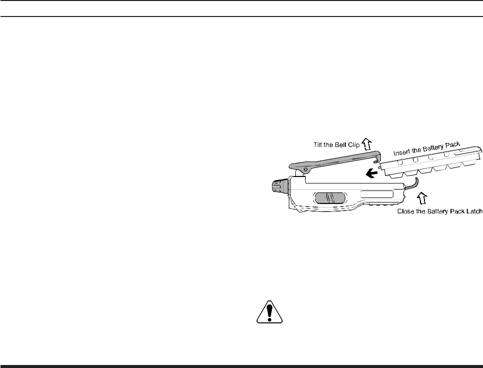
Battery Installation and Removal
¦To install the battery, hold the transceiver with
your left hand, so your palm is over the speaker
and your thumb is on the top of the Belt Clip.
Insert the battery pack into the battery compart-
ment on the back of the radio while tilting the
Belt Clip outward, then close the Battery Pack
Latch until it locks in place with a “Click.”
¦To remove the battery, turn the radio off and re-
move any protective cases. Open the Battery Pack
Latch on the bottom of the radio, then slide the
battery downward and out from the radio while
unfolding the Belt Clip.
Do not attempt to open any of the recharge-
able Ni-Cd packs, as personal injury or dam-
age to the Ni-Cd pack could occur if a cell or cells
become accidentally short-circuited.
VXA-120 AVIATOR PROII OPERATING MANUAL 9
the charger/battery. Contact your Dealer if you
have any doubts about the appropriateness of the
particular charger or battery pack you intend to
use.
BEFORE YOU BEGIN
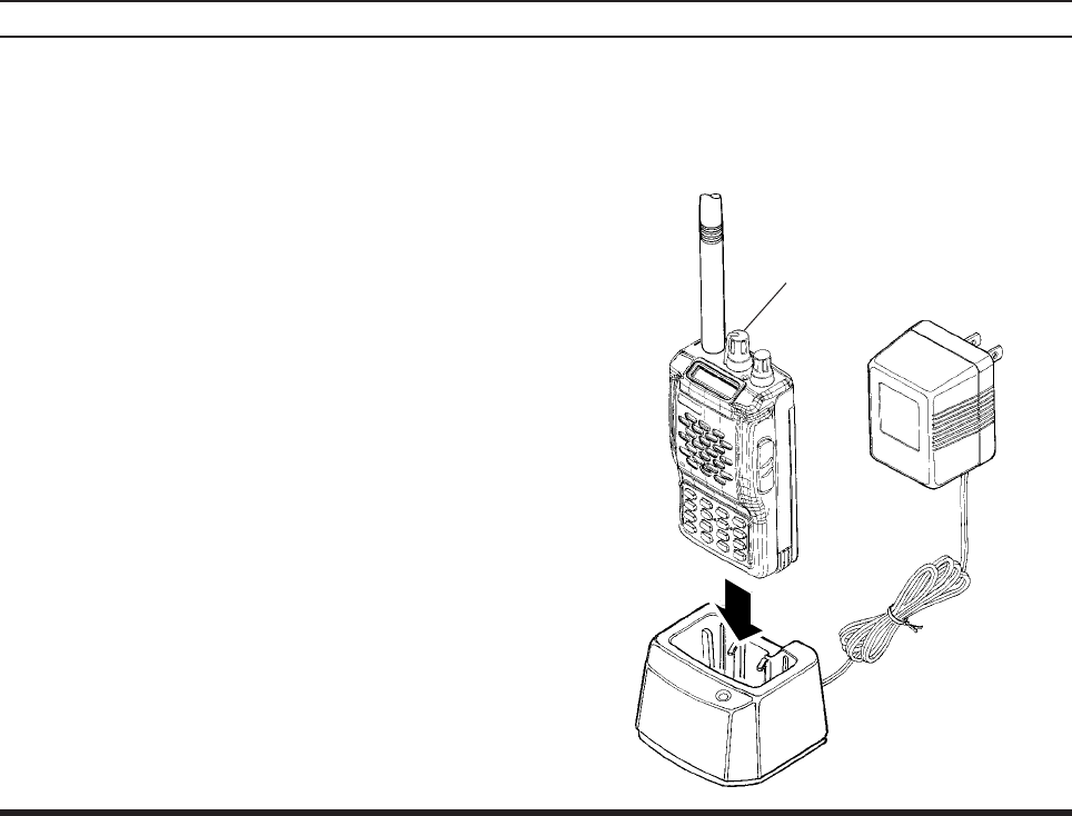
Battery Charging
It is necessary to fully charge the Ni-Cd battery be-
fore it’s first use. Follow these procedures:
¦Install the supplied FNB-V57 Ni-Cd battery pack
onto the transceiver. Ensure that the transceiver
is switched off.
¦Plug the NC-76 into the AC line outlet.
¦Insert the battery pack into the NC-76; the an-
tenna jack should be at the left side when view-
ing the charger from the front.
¦If the battery pack is inserted correctly, the RED
indicator will glow. A fully-discharged pack will
be charged completely in 15 hours.
Important Notes:
rThe NC-76 is not designed to power the trans-
ceiver for operation (reception or transmission).
rDo not leave the charger connected to the trans-
ceiver for continuous periods in excess of 24
hours. Long term overcharging can degrade the
Ni-Cd battery pack and significantly shorten its
useful life.
rIf using a charger other than the NC-76, or if
using a battery pack other than the FNB-V57,
follow the appropriate instructions provided with VXA-120/NC-76
To AC line outlet
Must be transceiver
switched off.

VXA-120 AVIATOR PROII OPERATING MANUAL
10
Low Battery Indication
¦As your battery discharges during use, the volt-
age will gradually become lower. When the bat-
tery voltage reaches 5.0 Volts, the “ x” icon
will blink on the LCD display, indicating that
the battery pack must be recharged before fur-
ther use.
¦Avoid recharging Ni-Cd batteries before the
“Low Battery” indicator is observed, as this can
degrade the charge capacity of your Ni-Cd bat-
tery pack. Yaesu recommends that you carry an
extra, fully-charged pack with you so you will
not lose communications capability due to a de-
pleted Ni-Cd battery.
This “deep cycling” practice will help to main-
tain longer overall battery life after many recharg-
ing cycles.
BEFORE YOU BEGIN
Installing the FBA-25 (option) Alkaline
Battery Case
The optional FBA-25 Battery Case allows opera-
tion of the VXA-120 using six “AA” size Alkaline
batteries.
When installing batteries, insert the (–) end first, then
press in the (++
++
+) end so the battery snaps into place.
Always replace all six batteries at the same time, pay-
ing attention to the polarity indicated inside the case.
The FBA-25 must not be used with re-
chargeable cells. The FBA-25 does not con-
tain the thermal and over-current protection cir-
cuits (provided in the “FNB” series of Ni-Cd Bat-
tery Packs) required when utilizing Ni-Cd cells.
VXA-120 AVIATOR PROII OPERATING MANUAL 11
OPERATION
Preliminary Steps
¦Install a charged battery pack onto the transceiver,
as described previously.
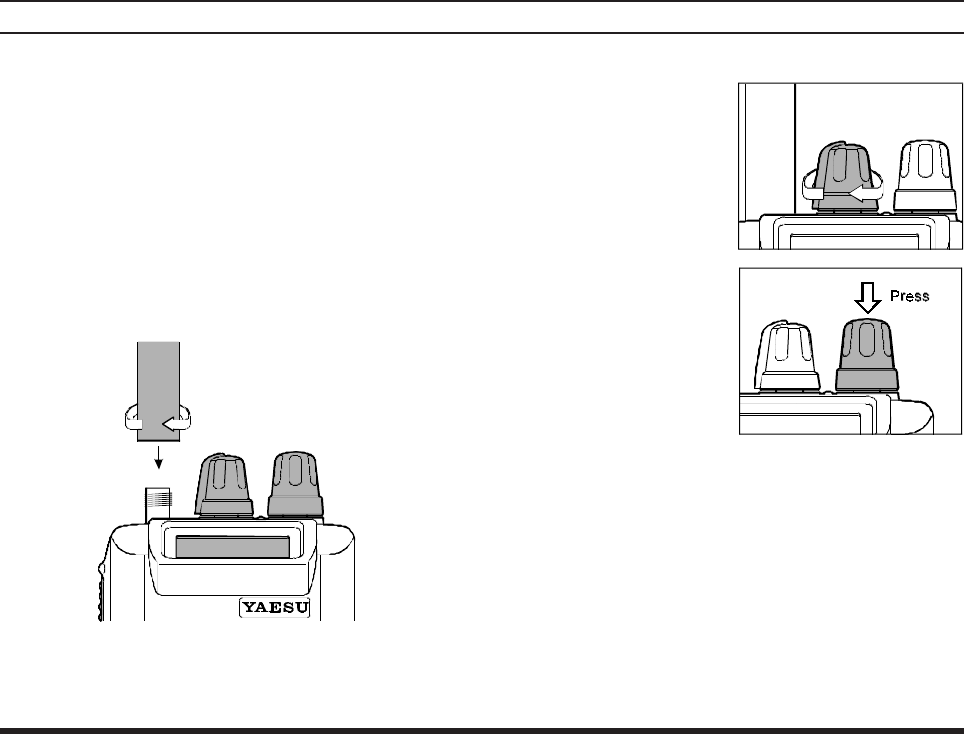
¦Screw the supplied antenna onto the Antenna
jack. Never operate this transceiver without an
antenna connected.
¦If you have an optional Speaker/Microphone or
headset, we recommend that it not be connected
until you are familiar with the basic operation of
the VXA-120.
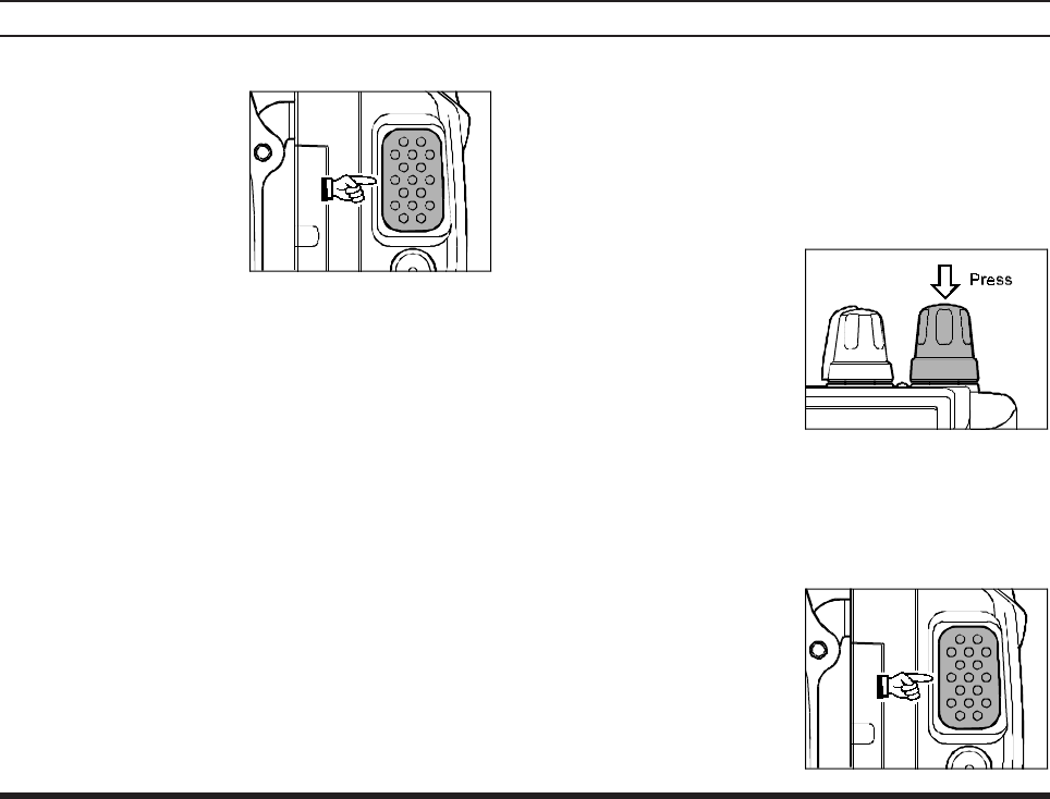
Operation Quick Start
rTo turn the radio on,
rotate the VOLUME
knob out of the click-
stop.
rAfter three “initial-
ization” beeps are
heard, a channel fre-
quency should ap-
pear on the display. If
not, press downward
(momentarily) on the
CHANNEL selector knob (repeatedly, if neces-
sary) so that “" VFO "” appears on the display,
followed by a channel frequency.
rDirectly entering frequencies from the Keypad
is the easiest method if you know the frequency
on which you wish to operate. Just enter the five
digits of the frequency to move to that frequency.
For example, to set 134.35 MHz,
press [1] à [3] à [4] à [3] à [5].
VXA-120 AVIATOR PROII OPERATING MANUAL
12
To set 118.275 MHz, you do not need to press
the final “5” in the frequency:
[1] à [1] à [8] à [2] à [7].
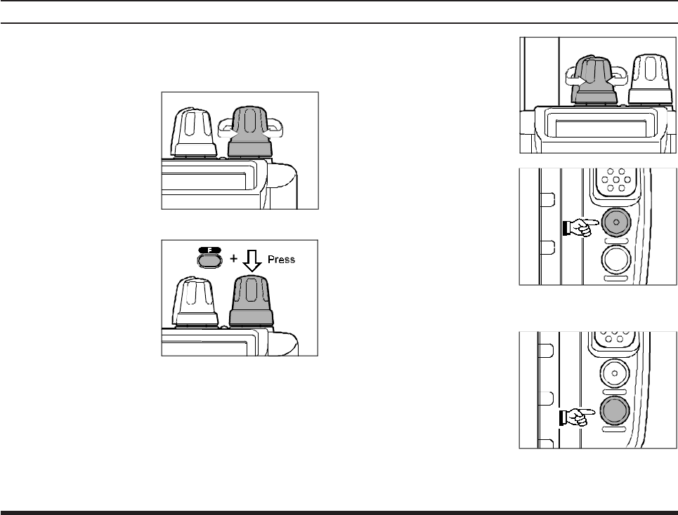
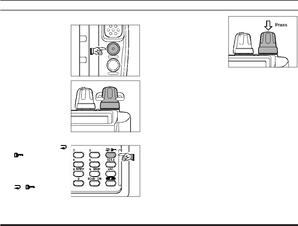
rYou may also turn
the top panel’s
CHANNEL selector
knob to choose the
desired operating fre-
quency. The channel
frequency will ap-
pear on the LCD.
rTo change frequency
in 1 MHz steps, press
the [F] key momen-
tarily, then rotate the
CHANNEL selector
knob to select the
MHz digit desired.
Press [F] once more to resume normal channel
selection in 25-kHz steps.
OPERATION
rRotate the VOL-
UME knob to set the
volume level. If no
signal is present,
press and hold the
MONITOR button
for 2 seconds; back-
ground noise will
now be heard, and
you may use this
noise to set the VOL-
UME knob for the
desired audio level.
Press the MONITOR
button momentarily, to silence the noise and re-
sume normal (quiet) monitoring.
rPress and hold the
LAMP button for 2
seconds, to illumi-
nate the display and
keypad continuously.
To disable the illumi-
nation, press the
LAMP button momentarily.
VXA-120 AVIATOR PROII OPERATING MANUAL 13
rTo turn the radio off, turn the VOLUME knob
fully counter-clockwise into the click stop posi-
tion.
OPERATION
Accessing the 121.5 MHz Emergency Frequency
The VXA-120 can quickly access the 121.500 MHz
Emergency Frequency. This function can be activated
even when the keypad lock function is in use.
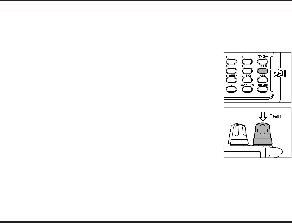
rTo access the Emer-
gency Frequency,
press the [121.5] key
momentarily.
rTo exit the Emer-
gency Frequency,
press the CHAN-
NEL selector knob.
VXA-120 AVIATOR PROII OPERATING MANUAL
14
Tuning Methods
Throughout this manual, you will see references to
several different frequency setting methods. Each will
be particularly useful in a particular operating situa-
tion, and they are described below:
¦VFO (Variable Frequency Oscillator)
The VFO is a “tuning
dial” system which al-
lows you to tune
through the NAVNAV
NAVNAV
NAV or COMCOM
COMCOM
COM bands in 25-kHz steps
using the CHANNEL selector, the Keypad, or
the scanner.
¦MR (Memory Recall)
The MR (Memory Re-
call) mode of the VXA-
120 provides the user
with the ability to store and recall as many as 50
channels in the radio’s main memory bank. These
memory channels may also be labeled by you
with an alpha/numeric name of up to 8 charac-
ters in length, to aid in quick identification of
the channel. See page 20 for details on creating
alpha/numeric labels.
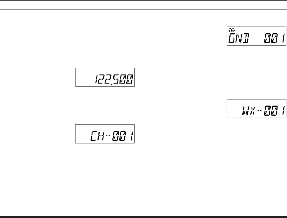
¦BOOK (Pre-Programmed) Memories
The Book memories are
pre-programmed, either
at the factory or by your
Dealer (depending on your country’s require-
ments), typically including the major COMCOM
COMCOM
COM and
NAVNAV
NAVNAV
NAV band station frequencies used in your area.
The Book memories can be changed by the user.
See page 27 for details.
¦WX (Weather Channel) Memories
Ten Weather Channels
are pre-programmed at
the factory as appropri-
ate for your country, and the VXA-120 will au-
tomatically scan this special bank when it is se-
lected by the user.
OPERATION
VXA-120 AVIATOR PROII OPERATING MANUAL 15
Transmission
To transmit, press and
hold the PTT switch.
Speak into the micro-
phone area of the front
panel grille in a normal
voice level.
To return to the receive
mode, release the PTT switch.
Reception of Weather Channel Broadcasts
The VXA-120 can receive VHF Weather Channel
broadcasts, which may assist your flight planning.
The VXA-120 includes a ten-channel auto-search
feature, which simplifies access to Weather Chan-
nels when you are in an unfamiliar location.
rTo receive Weather
Channels, press the
CHANNEL selector
knob (repeatedly, if
necessary) to select
the Weather Channel
mode. In the Weather
Channel mode, “" WX "” will appear on the dis-
play.
rThe VXA-120 will now scan quickly through the
ten standard Weather Channels, and will stop on
the first active station found.
rIf there are two or
more weather chan-
nels audible in your
area, you may select
the alternate chan-
nel(s) by pressing the
PTT switch. Pressing
OPERATION
VXA-120 AVIATOR PROII OPERATING MANUAL
16
OPERATION
the PTT switch re-initiates the scanning process.
rIf there are no
Weather Channels in
your area, the scan-
ner will not stop.
Press the MONITOR
button to stop the
scanner.
rYou can also select
Weather Channels
manually by rotating
the CHANNEL se-
lector knob.
rTo comfirm the current Weather Channel fre-
quency, press the [
()] key momen-
tarily. The display
changes
to frequency
indication. Press the
[ ()] key again
to return to normal
display.
rTo exit the Weather
Channel mode, press
the CHANNEL se-
lector knob momen-
tarily to return to the
VFO mode.
Note: The Weather Channel mode memorizes the last
Weather Channel you have used, and will retain this
information until the radio is turned off.
VXA-120 AVIATOR PROII OPERATING MANUAL 17
Monitor Key
When listening to a very weak signal from an air-
craft or ground station, you may observe the signal
disappearing periodically as the incoming signal
strength becomes too weak to override the squelch
threshold setting.
To disable the squelch
temporarily, press and
hold the MONITOR key
for 2 seconds on the left
side of the radio, just be-
low the PTT button. The
squelch will remain open
and you should have a better chance of hearing weak
signals.
To return to normal operation, press the MONITOR
key momentarily.
OPERATION
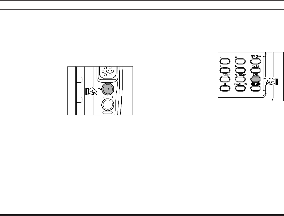
ANL (Automatic Noise Limiter) Feature
For reduction of impulse noise, such as that produced
by an engine’s ignition system, the ANL feature may
prove helpful.
rTo activate the ANL
feature, press the
[ANL] key momen-
tarily. The “
ANL
”
icon will appear on
the display, and you
should observe a re-
duction in the ignition noise.
rTo turn the ANL feature off, repeat the above
step; the “
ANL
” icon will disappear from the dis-
play.
VXA-120 AVIATOR PROII OPERATING MANUAL
18
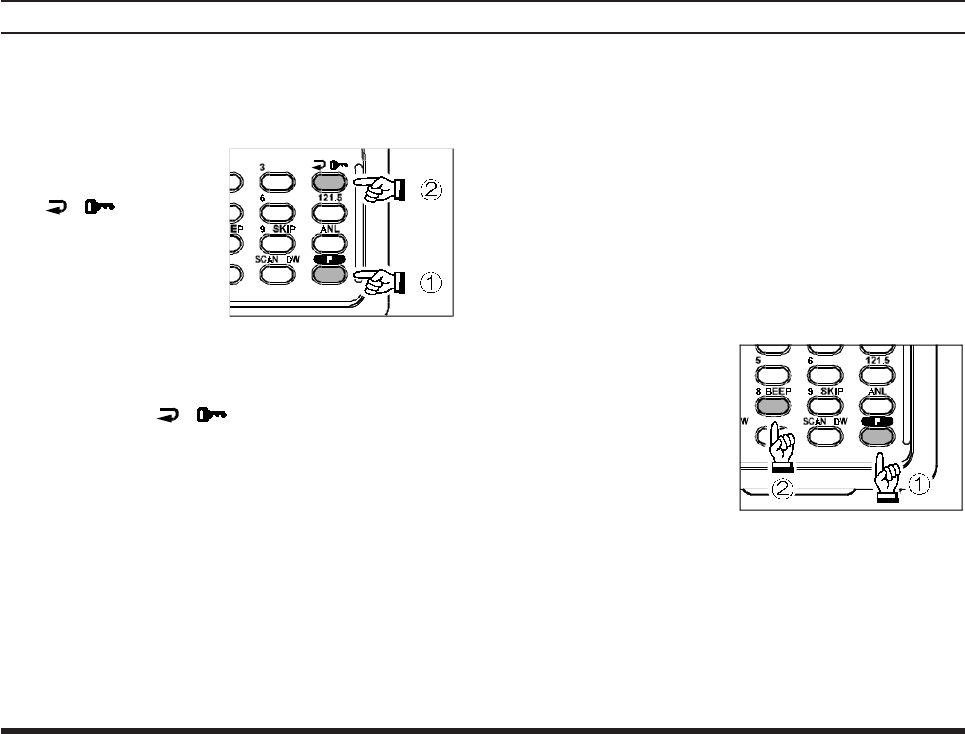
LOCK Function
The lock function prevents accidental changes to the
frequency setting and the keypad controls.
rTo activate the lock
feature, press [F] à
[ ()] key.
rIn the LOCK mode,
the display will show
“" LOCK"” when
you rotate the
CHANNEL selector knob, press the CHANNEL
selector knob, or touch a key on the keypad.
rTo turn the lock feature off,
press [F] à [ ()] again.
rYou can still access the 121.500 MHz Emergency
Frequency when the LOCK function is on.
Simply press the [121.5] key momentarily (this
key never locks). Pressing this key also unlocks
the radio.
OPERATION
Beep On/Off
The VXA-120’s key/button beeper provides conve-
nient audible feedback whenever a button is pressed.
Each key and button has a different beep pitch, and
each function has a unique beep combination.
When you are scanning, the beeper will be heard each
time the scanner halts on a busy channel. This may
be distracting in some environments; if you want to
turn the beeper off (or back on again):
rPress [F] à [8 (BEEP)] key; “ BEEP on” will
appear on the LCD.
rRotate the CHAN-
NEL selector knob
one click to change
the display to
“BEEP oFF.”
rPress the [8(BEEP)]
key again to save your new setting and exit to
normal operation.

VXA-120 AVIATOR PROII OPERATING MANUAL 19
NOTE

VXA-120 AVIATOR PROII OPERATING MANUAL
20
MEMORY OPERATION
The VXA-120 provides 50 user-programmable
“Main” memories, labeled “ CH" ))! ” through
“CH" )%),” and up to 100 pre-programmed memo-
ries, designated “Book” Memories. The “ ” icon
appears when “Book” Memory Mode is activated.
The Main memories and “Book” Memories can be
assigned alpha-numeric names of up to eight charac-
ters.
Memory System Operation
The VXA-120’s Main Memory system allows the
user to store, label, and recall channel frequencies
which you may want to use frequently. You may store
VFO frequencies, Book Memory frequencies, and/
or Weather Channel frequencies into the Main
Memory system.
Memory Storage
rSelect the desired frequency in the VFO mode,
or recall the Book Memory channel or Weather
channel to be stored in the Main Memory.
rPress and hold the [MW (SPL.W)] key for 2
seconds. The display will indicate “ CH" ” and a
channel number will blink on the LCD.
rWithin five seconds of pressing the [MW
(SPL.W)] key, rotate the CHANNEL selector
knob to select the desired memory channel num-
ber for storage.
In order to prevent writing over memory chan-
nels, a bar will appear under the hyphen (located
between “ CH” and the channel number) to indi-
cate a vacant memory channel.
rNow press and hold in the [MW (SPL.W)] key
for 2 seconds; you will now see “;""""""""""""""
""""""""""""""
"""""""”
on the LCD. To attach an alpha/numeric name
(label) to the memory, proceed to the next step;
otherwise press and hold [MW (SPL.W)] for 2
seconds to save the entry and exit.
rTo label a memory with an alpha/numeric name,
the next step is to use the CHANNEL selector
knob to select any of the 48 available characters
(including letters, numbers, and special symbols).
VXA-120 AVIATOR PROII OPERATING MANUAL 21
When the desired first character appears, press
the CHANNEL selector knob momentarily to
move on to the next character.
rSelect succeeding characters in the same man-
ner, pressing the CHANNEL selector knob mo-
mentarily after each selection.
rAfter entering the entire name (eight characters
maximum), press the [MW (SPL.W)] key for 2
seconds to save all data for the channel and exit.
Note: If you have stored a Weather Channel, the
“WX"))! ~ WX")!) ” labels utilize the alphanu-
meric memory, and other labels may not be stored.
Recalling the Memories
rPress the CHANNEL selector knob, repeatedly
if necessary, until “MR” (Memory Recall) ap-
pears on the display. In the MR mode, you will
see “ CH" ” and the previously selected channel
number appearing on the LCD.
rRotate the CHANNEL selector knob to select
the desired memory channel.
rYou may change the title structure of the Memory
display type among:
1. Channel Indication (sequential Channel Number,
e.g. CH"))!, CH"))@, etc.);
2. Frequency Indication (e.g. 1@@.%))); or
3. Alphanumeric Label (e.g. LAX FSS).
rTo change the Memory display title, press the
[ ()] key repeatedly, if necessary, until you
get the desired display title structure.
rTo exit the Memory mode, press the CHANNEL se-
lector knob momentarily to return to the VFO mode.
Note: In the “Book” Memory mode, you can change
the memory channel in 10 channel steps, press the
[F] key momentarily, then rotate the CHANNEL se-
lector knob. The “ ” icon will show at the right
edge of the display when the 10 channel step tuning
mode is active. Press the [F] key once more to re-
sume normal channel selection in 1 channel step.
MEMORY OPERATION
A
AA
Al
ll
lp
pp
ph
hh
ha
aa
a-
--
-t
tt
ta
aa
ag
g g
g C
CC
Cha
haha
har
rr
rac
acac
act
tt
to
oo
or
rr
r
) ! @#$%^&*(AB
CDEFGHIJKLMN
OPQRSTUVWXYZ
<>+;:\`y[|"

VXA-120 AVIATOR PROII OPERATING MANUAL
22
SCANNING OPERATION
The VXA-120 allows you to scan automatically in
the VFO*, Main Memory, “Book” Memory, or
Weather Channel modes. It pauses on signals encoun-
tered, so you can talk to the station(s) on that fre-
quency, if you like.
* In the VFO mode, the automatic scanner is only
available in the COMCOM
COMCOM
COM band (118.000 - 136.975 MHz);
when the scanner reaches the uppermost frequency
in the COMCOM
COMCOM
COM band, it will revert to the bottom end of
the COMCOM
COMCOM
COM band and repeat the scanning process until
you cancel the scanning process.
If you wish to scan in the NAVNAV
NAVNAV
NAV band (108.000 -
136.975 MHz), you can do so manually, as described
at the right.
Scanning operation is basically the same in each of
the above modes.
rPress the [SCAN (DW)] key momentarily to start
the automatic scanner upward (toward a higher
frequency or a higher channel number).
rWhen the scanner encounters a signal, scanning
pauses and the radio remains on that channel until
one second after the signal disappears, after
which scanning will resume.
rWhile the scanner remains paused on a frequency,
the decimal point of the frequency display blinks.
The display and keypad will be illuminated un-
less the Scan Lamp Feature is turned off.
rTo change the scan direction, turn the CHAN-
NEL selector knob one click in the opposite di-
rection.
rTo stop the automatic scanner, press the PTT switch
or the CHANNEL selector knob momentarily. You
may also press [SCAN (DW)] key again.
The VXA-120’s automatic scanner is not operational
in the NAVNAV
NAVNAV
NAV band (108.000 - 117.975 MHz), because
the NAVNAV
NAVNAV
NAV stations (ILS, etc.) transmit constantly
(thereby causing the scanner to stop repeatedly).
However, you can scan manually in the NAVNAV
NAVNAV
NAV band,
per the following procedure:
rPress and hold the [SCAN (DW)] key to start
the manual scanner. Scanning will continue as
long as the key is depressed.
rRelease the [SCAN (DW)] key to stop the
manual scanner immediately.
Note: When scanning upward in frequency, when the
frequency reaches the COMCOM
COMCOM
COM Band (118.000 - 136.975
MHz) via manual scanning, the VXA-120 will switch
to the automatic scanner mode.

VXA-120 AVIATOR PROII OPERATING MANUAL 23
SCANNING OPERATION
Channel-Skip Scanning
Continuous-carrier stations like ATIS (Automatic
Terminal Information Service) or Weather Broadcast
stations inhibit scanner operation. Since these sta-
tions are always active, the scanner will be halted
repeatedly on their channels. Such channels can be
set to be “skipped” during scanning, if you like, so
as not to interfere with automatic channel scanning:
rRecall the Memory Channel to be skipped dur-
ing scanning.
rPress [F] à [9 (SKIP)] key. The “SKIP” icon
will appear in the lower right corner, indicating
that the channel is to be ignored during scanning.
rYou can also designate a channel to be skipped
while scanning. When the receiver is halted on a
channel that you wish to skip, press and hold the
[SCAN (DW)] key for 2 seconds (the “SKIP”
icon will appear next to the channel to be
skipped).
rLater, to re-enable the memory channel for scan-
ning, repeat the first two steps. The “SKIP” icon
will disappear by the channel you have just re-
enabled.
Note: A memory set to be “skipped” is still acces-
sible for manual memory selection using the CHAN-
NEL selector knob.

VXA-120 AVIATOR PROII OPERATING MANUAL
24
DUAL WATCH OPERATION
The Dual Watch feature automatically checks for
activity on a “priority” channel* while you are oper-
ating on another channel. During Dual Watch opera-
tion, the current channel and the Priority channel will
each be polled for a 500 ms interval, as the VXA-
120 looks for activity on each channel.
rTo start Dual Watch, press [F] à [SCAN (DW)].
The “DW” icon will appear on the display.
rWhile receiving on the “current” channel (not
the Priority channel), you may push the PTT
switch at any time to transmit on that channel.
rWhen a signal is received on the Priority chan-
nel, operation immediately shifts to the Priority
channel, the “DW” icon will blink, and the dis-
play and keypad will become illuminated.
While receiving on the priority channel, if you
momentarily press the PTT switch, Dual Watch
will be disabled. You may then transmit on the
Priority Channel.
rTo stop Dual Watch, press [F] à [SCAN (DW)]
key.
rIf you wish, you may use both the Dual Watch
and Scan features simultaneously. To do this, start
the Dual Watch first, then start the Scanner.
* The “Priority” Channel is defined as the last-used
Memory Channel (when using the VFO mode) or
Memory Channel 1 (when using the Main Memory
or Book Memory modes).

VXA-120 AVIATOR PROII OPERATING MANUAL 25
PRIORITY DUAL WATCH OPERATION
Similar to Dual Watch operation (described above),
Priority Dual Watch is an enhanced version which
includes the following additional features:
lThe receiving time interval (ratio) between the
current channel and the Priority channel may be
customized via the Menu mode, item PRTM. See
page 28 for details.
lIrrespective of which channel is currently being
received, when the PTT button is pushed trans-
mission will always occur on the Priority chan-
nel.
Before initiating Priority Dual Watch, Menu item
DWMD must be set to the “Priority” mode (instead
of “Dual Watch”). See page 28 for details.
rTo start Priority Dual Watch, press [F] à [SCAN
(DW)].
The “DW” icon will appear on the display.
rWhile receiving on the “current” (non-Priority)
channel, pressing the PTT button once causes
the radio to switch to the Priority channel and
cancels Dual Watch. Press the PTT button again
to transmit on the Priority channel.
rWhen a signal is received on the Priority chan-
nel, reception immediately shifts to the Priority
channel, “DW” icon will blink, and the display
and keypad will become illuminated unless the
Scan Lamp Feature is turned off.
While receiving on the priority channel, if you
momentarily press the PTT switch, Priority Dual
Watch will be disabled. You may then transmit
on the Priority Channel.
rTo stop Priority Dual Watch, press [F] à [SCAN
(DW)] key.

VXA-120 AVIATOR PROII OPERATING MANUAL
26
The split operation feature allows you to transmit a
call to a Flight Service Station using the COMCOM
COMCOM
COM band
frequencies, while receiving a NAVNAV
NAVNAV
NAV band station
(such as the ATIS, AWOS etc.). NAVNAV
NAVNAV
NAV band stations
equipped with this capability typically are shown,
on navigation charts, with the voice calling frequency
in parenthesis above the navigation frequency.
Programming a Transmit Frequency
rPress the CHANNEL selector knob, repeatedly
if necessary, to select the VFO mode.
rSet a NAVNAV
NAVNAV
NAV band (108.000 - 117.975 MHz) fre-
quency using the CHANNEL selector knob or
keypad.
rPress [F] à [MW (SPL.W)] key. The “SPL”
icon will blink, and the transmit frequency will
appear on the display.
rNow set your radio’s transmit frequency, where
the Flight Service Station will be listening for
calls, using the CHANNEL selector knob or key-
pad.
rPress and hold in the [MW (SPL.W)] key for 2
seconds to save the transmit frequency and re-
turn to the NAVNAV
NAVNAV
NAV band frequency.
SPLIT OPERATION
Note: You have now stored the separate transmit fre-
quency, but you have not yet activated the split-fre-
quency function; go on to the next section.
Operating in the Split Mode
rIt is assumed that you have already set the de-
sired NAVNAV
NAVNAV
NAV band station’s frequencies per the
above instructions.
rPress [F] à [7 (SPL)] to turn on the “Split”
function. The “SPL” icon will appear on the dis-
play.
rPress and hold in the PTT switch to transmit on
the split transmit frequency.
rRelease the PTT switch to return to the receive
mode.
rTo disable the “Split” function, press [F] à [7
(SPL)] again.
Note: A split frequency can be programmed into each
memory channel independently. Set a transmit fre-
quency before programming the memory channel, if
desired. The split function on/off setting can also be
programmed into a memory channel.

VXA-120 AVIATOR PROII OPERATING MANUAL 27
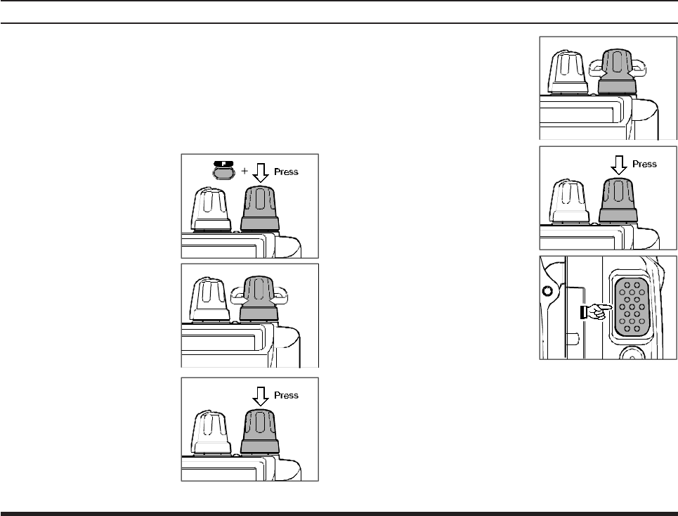
FIELD PROGRAMMING MODE
The VXA-120’s Book Memoris also allows the user
to store, label, and recall channel frequencies which
you may want to use frequently while the VXA-120
is in the Field Programming mode.
Memory Storage into the Book Memory
rPress and hold the PTT and LAMP switch while
turning the radio on, to activate the Field Pro-
gramming Mode.
rSelect the desired frequency to be stored in the
Book Memory.
rPress and hold the [MW(SPL.W)] key for 2 sec-
onds. The display will indicate “BOOK;” and a
channel number will blink on the LCD.
rWithin five seconds of pressing the
[MW(SPL.W)] key, rotate the CHANNEL se-
lector knob to select the desired memory chan-
nel number for storage.
rNow press and hold in the [MW(SPL.W)] key
for 2 seconds; you will now see “;""""""" ”
on the LCD. To attach an alpha/numeric name
(label) to the memory, proceed to the next step;
otherwise press and hold the [MW(SPL.W)] key
for 2 seconds to save the entry and exit.
rTo label a memory with an alpha/numeric name,
the next step is to use the CHANNEL selector
knob to select any of the 48 available characters
(including letters, numbers, and special symbols).
When the desired first character appears, press
down on the CHANNEL selector knob momen-
tarily to move on to the next character.
rSelect succeeding characters in the same man-
ner, pressing down on the CHANNEL selector
knob momentarily after each selection.
rAfter entering the entire name (eight characters
maximum), press the [MW(SPL.W)] key for 2
seconds to save all data for the channel.
rTurn the radio off, then turn the radio back on
again to begin normal operation.
VXA-120 AVIATOR PROII OPERATING MANUAL
28
MENU (“SET”) MODE
The Menu system allows certain aspects of your
radio’s configuration to be customized for your per-
sonal operating convenience. We do not recommend
that any of the default settings be changed, however,
until you are thoroughly familiar with the operation
of the VXA-120.
1. Press the [F] key, then
press the CHANNEL
selector knob to activate
the Menu (“SET”)
mode.
2. Rotate the CHANNEL
selector knob to select
the Menu item (feature)
you wish to view and/or
modify.
3. Once you have selected
the desired Menu Item,
press the CHANNEL
selector knob once to
view the current setting
for the item.
4. Rotate the CHANNEL
selector knob to change
the setting of the item
(ON to OFF, etc.).
5. Press the CHANNEL
selector knob to save
your new setting.
6. If you need to change
more than one Menu
item, repeat steps 2 - 5.
7. Press the PTT switch to
exit the Menu (“SET”)
mode.
VXA-120 AVIATOR PROII OPERATING MANUAL 29
MENU (“SET”) MODE
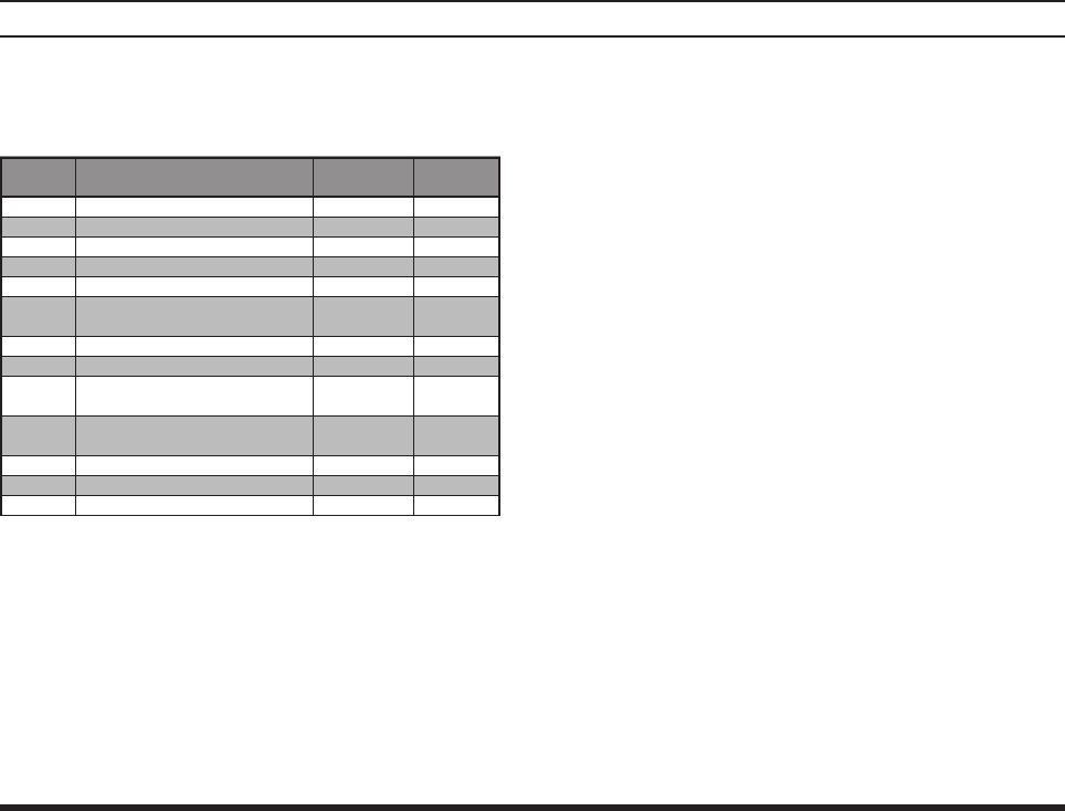
MENU Listing
A listing of the Menu items available via the SET
mode may be found below.
SQL
Function: Squelch Level Setting
Available Values: 0 ~ 8
Default Setting: 3
Select a setting for this Menu item which just silences
the receiver when no signal is present. Use the low-
est setting which will keep the receiver quiet between
incoming transmissions.
MCLR
Function: Memory Channel Clear
To Clear a Memory channel:
1. Select the Menu Item MCLR.
2. Press the CHANNEL selector knob, then rotate
the CHANNEL selector knob to recall the
memory channel to be erased (“SET xx” will
appear on the display).
3. Press the VOLUME knob, then turn the CHAN-
NEL selector knob one click to change the dis-
play to “CLR xx”.
4. Press and hold the CHANNEL selector knob for
2 seconds to exit.
Important Notice: An “erased” channel cannot be
restored, and “ CH"OO1 ” cannot be erased, as it is
used for “Priority Channel” operation.
Menu
Item
SQL
MCLR
RESE
SCNL
BEEP
RSAV
LAMP
SFT
PRTM
DWMD
POBP
LCD
IMIC
Function
SQLSquelch Level Setting
Memory Channel Clear
Scan-Resume Mode Setting
Scan Lamp On/Off
Keypad Beeper On/Off
Receiver Battery Saver
LCD Illumination Mode
CPU Clock Shift
Priority Checking Time
Select the
Dual Watch/Priority Function
Select the Power on Beep
Select the LCD Display Readout
Internal Microphone On/Off
Available
Values
0 ~ 8
–
CAR/5
on/oFF
on/oFF
oFF/ABS/
1:1 ~ 1:5
KEY/TGL/5
on/oFF
05/10/15/
20/25/30
DW/PRI
1/2/3/oFF
NOR/INV
on/oFF
Default
3
–
CAR
on
on
oFF
KEY
oFF
15
(1.5 sec)
DW
1
NOR
on

VXA-120 AVIATOR PROII OPERATING MANUAL
30
RESM
Function: Scan-Resume Mode Setting
Available Values: CAR/5
Default Setting: CAR
In the “CAR” (Carrier Drop) mode, the scanner will
remain halted for as long as there is a carrier present
on the channel; after the carrier drops at the end of
the other station’s transmission, the scanning will
resume.
In the “5” (5-Second Pause) mode, the scanner will
halt for five seconds only, after which scanning will
resume (whether or not the other station is still trans-
mitting).
SCNL
Function: Scan Lamp On/Off (while paused)
Available Values: on/oFF
Default Setting: on
If you set this function to “on,” the lamp will be illu-
minated whenever the scanner stops.
BEEP
Function: Keypad Beeper On/Off
Available Values: on/oFF
Default Setting: on
If you do a lot of scanning, you may wish to set this
Menu item to “oFF,” as the Beeper will be heard each
time the scanner halts.
RSAV
Function: Receive Battery Saver
Available Values: oFF/ABSø/1:1 ~ 1:5
Default Setting: oFF
The setting of 1:5 will promote the greatest conser-
vation of battery capacity, but the receiver’s response
time to incoming calls will be slowed somewhat.
øABS: Automatic Battery Saver, based on activity
on receiver
Note: This feature does not operate during Scan or
Dual Watch.
MENU (“SET”) MODE

VXA-120 AVIATOR PROII OPERATING MANUAL 31
LAMP
Function: LCD Illumination Mode
Available Values: KEY/TGL/5
Default Setting: KEY
In the “KEY” mode, the lamp will be activated for 5
seconds when a front panel key is pressed.
In the “TGL” mode, the LAMP switch toggles the
lamp on and off.
In the “5” mode, the LAMP switch activates the
lamp for 5 seconds.
SFT
Function: CPU Clock Shift
Available Values: on/oFF
Default Setting: oFF
This function is only used to move a spurious response
“birdie” should it fall on a desired frequency. Consult
your Yaesu dealer for details regarding this function.
PRTM
Function: Priority Checking Time
Available Values: 05/10/15/20/25/30 (x0.1 sec)
Default Setting: 15 (1.5 seconds)
This Menu item allows you to define how often the
Priority Channel will be checked for activity.
Note: The Dual Watch Polling time is 500 mS (fixed).
MENU (“SET”) MODE
DWMD
Function: Select the Dual Watch/Priority Function
Available Values: DW/PRI
Default Setting: DW
In the DW mode, the VXA-120 will activate the Dual
Watch feature when you press [F] à [SCAN (DW)].
In the PRI mode, the VXA-120 will activate the Pri-
ority feature when you press [F] à [SCAN (DW)].
POBP
Function: Select the Power on Beep
Available Values: 1/2/3/oFF
Default Setting: 1
LCD
Function: Select the LCD Display Readout
Available Values: NOR/INV
Default Setting: NOR
IMIC
Function: Internal Microphone On/Off
Available Values: on/oFF
Default Setting: on
When operate the VXA-120 in noisy area, we rec-
ommend that use with the optional MH-44A4B
Speaker Microphone while this function set to “oFF.”

VXA-120 AVIATOR PROII OPERATING MANUAL
32
SPECIFICATIONS
General
Frequency Range: TX 118.000 - 136.975 MHz
RX 108.000 - 136.975 MHz
Weather Channels (WX-01 - WX-10)
Channel Spacing: 25 kHz
Emission Type:TXAM
RX AM & FM
Supply Voltage: 6.0 - 15.0 VDC
Current Consumption
: < 1 µA (power off)
(approx.) 22 mA (battery saver on, saver ratio 1:5)
56 mA (squelch off)
180 mA (receive)
900 mA (transmit 1.0 W Carrier)
Temperature Range: –10° to +60° C
Case Size
(WxHxD)
: 58 x 108.5 x 26.5 mm w/FNB-V57
Weight (approx.): 335 grams
with FNB-V57, antenna, and belt clip
Receiver
Circuit Type: Double-conversion superheterodyne
IFs: 35.4 MHz & 450 kHz
Sensitivity: <1 µV
(for 6 dB S/N with 1 kHz, 30 % modulation)
Selectivity: <8 kHz/–6 dB
Adjacent CH. Selectivity
: <25 kHz/–60 dB
AF Output
(@7.2 V)
: 0.4 W @ 8 Ohms, 10 % THD
Specifications are subject to change without notice or obligation.
Transmitter
Power Output
(@ 7.2 V)
: 3.5 W (PEP), 1.0 W (Carrier Power)
Frequency Stability: Better than ±10 ppm
(–10 °C to +60 °C)
Modulation System: Low Level Amplitude Modulation
Spurious Emission: > 60 dB below carrier
Int. Microphone Type: Condenser
Ext. Mic. Impedance: 150 Ohms
ACCESSORIES & OPTIONS
Supplied Accessories
Ni-Cd Battery Pack FNB-V57
Overnight Desktop Charger NC-76B/C/Uø
Helical Antenna ATV-7
Operating Manual
Warranty Card
Available Options
MH-44A4B Speaker Microphone
FBA-25 Alkaline Battery Case
NC-73B/C/UøDesktop Rapid Charger
E-DC-5B External Power Cable
CT-60 Headset Cable
CN-3 Antenna Adapter
ø:“
B
” suffix is for use with 117 VAC,
“
C
” suffix is for use with 220-240 VAC, or
“
U
” suffix is for use with 230 VAC.