Yaesu Musen VXA-150 Airband Transceiver User Manual C yasu VXA 150
Yaesu Musen Co., Ltd. Airband Transceiver C yasu VXA 150
UserManual.wiki
>
Yaesu Musen
>
VXA 150 User Manual
Operating Manual
Navigation menu
Upload a User Manual
Namespaces
Wiki Guide
HTML
PDF
Info
Views
User Manual
Discussion / Help
Navigation
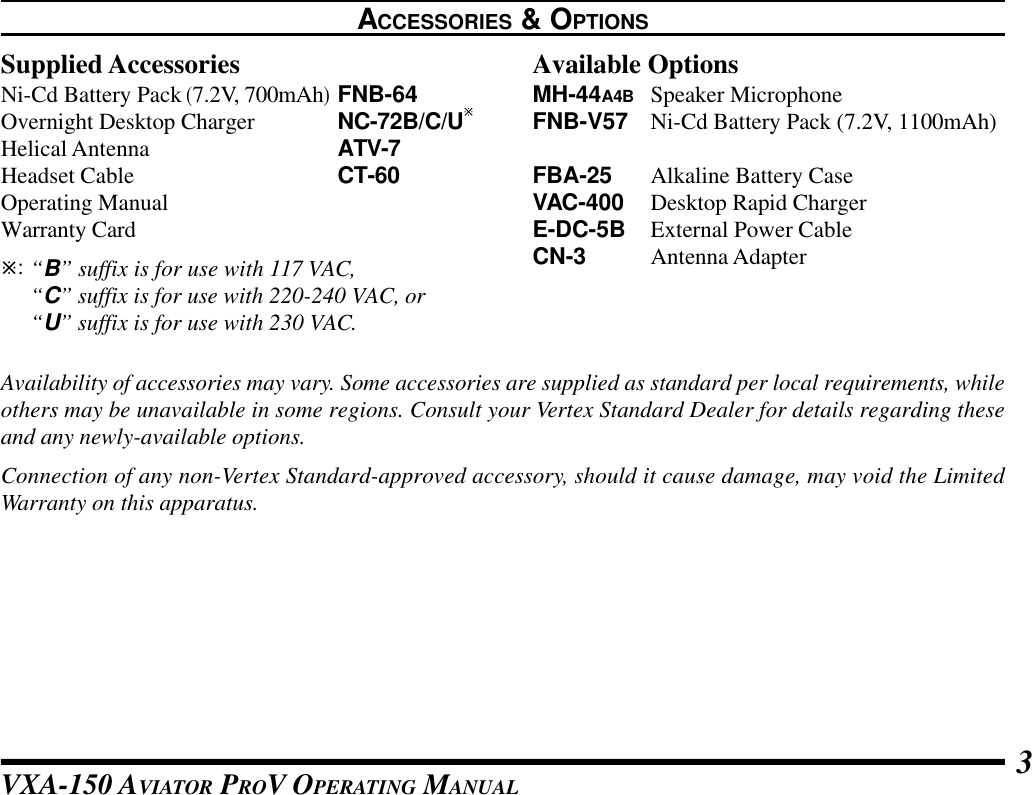
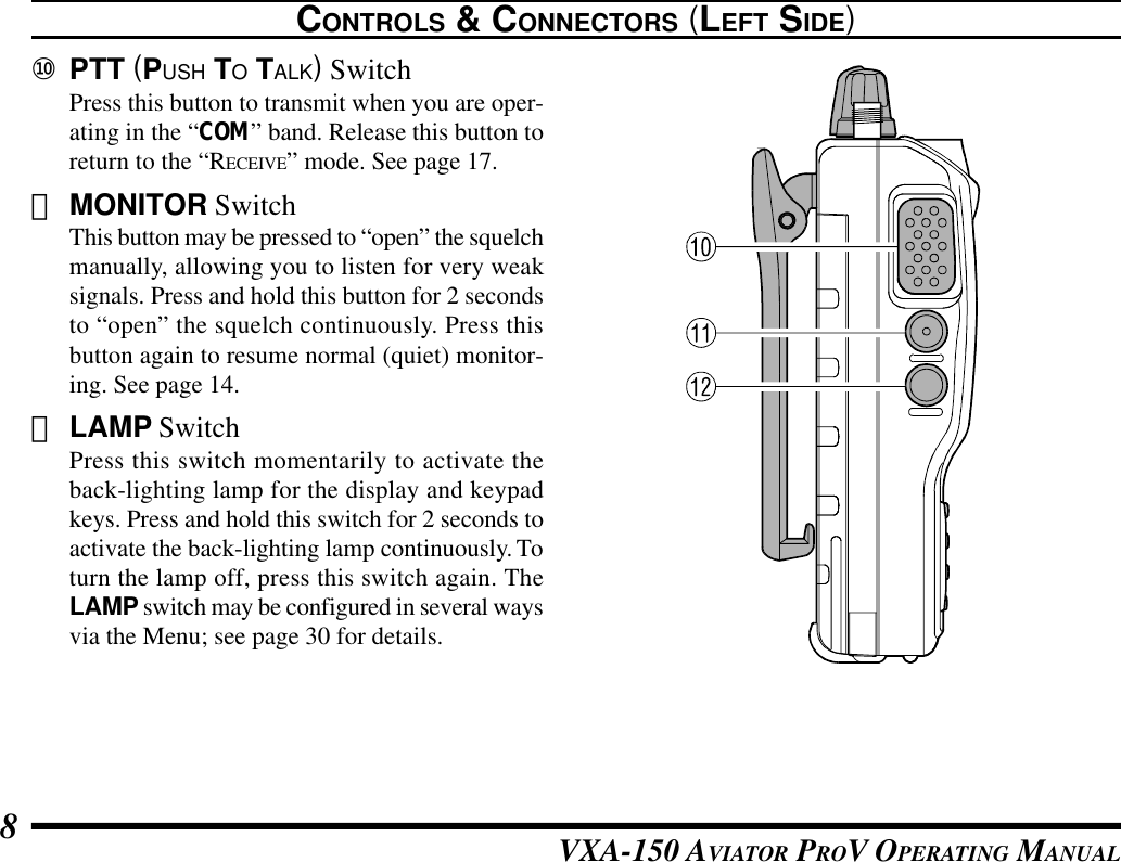
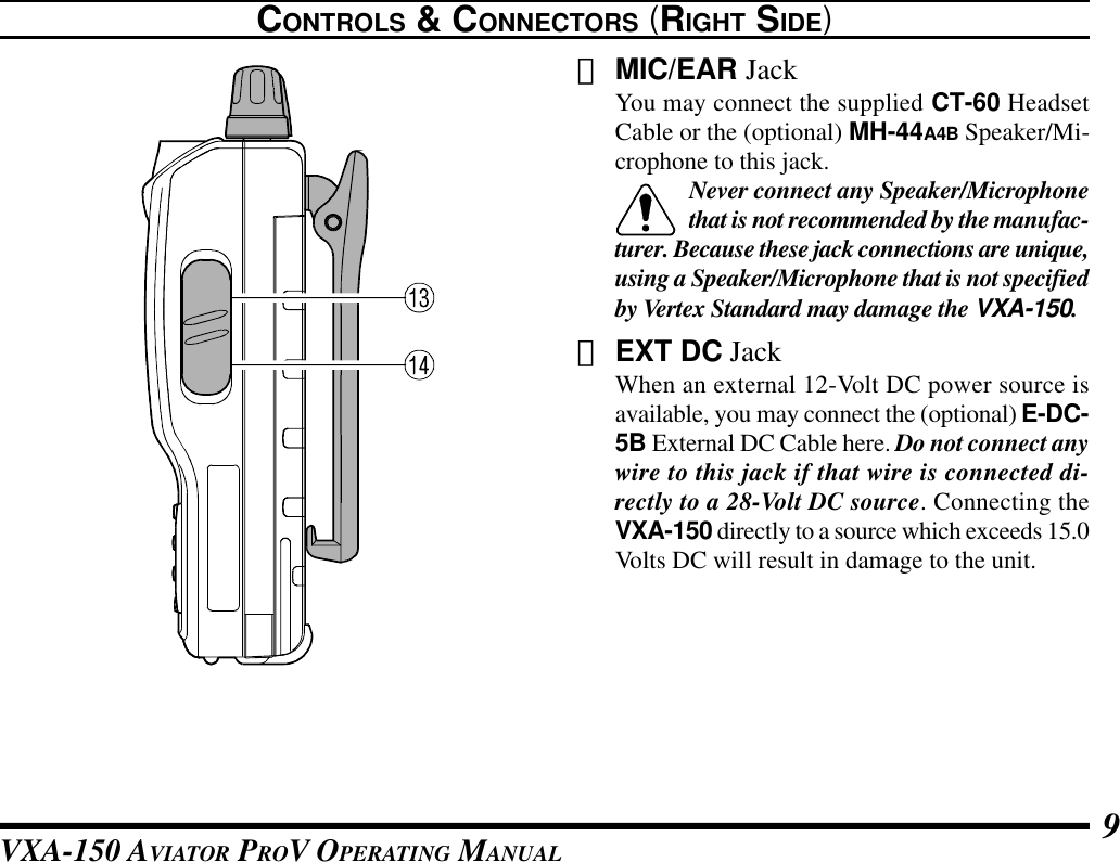
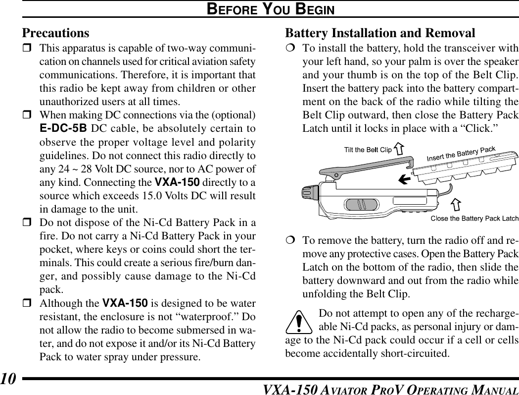
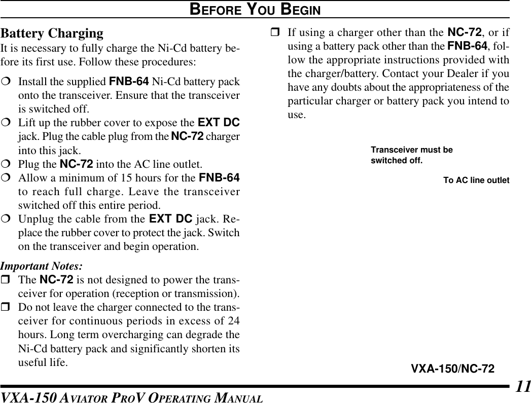
![VXA-150 AVIATOR PROV OPERATING MANUAL6CONTROLS & CONNECTORS (FRONT PANEL)⑥LoudspeakerThe internal speaker is located in this position.⑦MicrophoneSpeak across this opening in a normal voice levelwhile pressing the PTT switch.⑧KeypadSeveral keys have dual functions. The color ofthe label determines the way in which you acti-vate the function:The white labels represent the primary functionsof the keys (activated by simply pressing the keymomentarily).The yellow labels represent the secondary func-tions of the keys (activated by pressing the [F]key first, then the indicated key).On the keypad, primary functions (white) are la-beled to the left, while the secondary functions(yellow) are labeled to the right. These functionsare described in detail on the next page.⑨Battery Pack LatchOpen this latch for battery removal.](https://usermanual.wiki/Yaesu-Musen/VXA-150/User-Guide-171522-Page-8.png)
![VXA-150 AVIATOR PROV OPERATING MANUAL 13OPERATIONPreliminary Steps¦Install a charged battery pack onto the transceiver,as described previously.¦Screw the supplied antenna onto the Antennajack. Never operate this transceiver without anantenna connected.¦If you have an optional Speaker/Microphone orheadset, we recommend that it not be connecteduntil you are familiar with the basic operation ofthe VXA-150.Operation Quick StartrTo turn the radio on,rotate the VOLUMEknob out of the click-stop.rAfter three “initial-ization” beeps areheard, a channel fre-quency should ap-pear on the display. Ifnot, press downward(momentarily) on theCHANNEL selector knob (repeatedly, if neces-sary) so that “- VFO -” appears on the display,followed by a channel frequency.rDirectly entering frequencies from the Keypadis the easiest method if you know the frequencyon which you wish to operate. Just enter the fivedigits of the frequency to move to that frequency.For example, to set 134.35 MHz,press [1] à [3] à [4] à [3] à [5].](https://usermanual.wiki/Yaesu-Musen/VXA-150/User-Guide-171522-Page-15.png)
![VXA-150 AVIATOR PROV OPERATING MANUAL14To set 118.275 MHz, you do not need to pressthe final “5” in the frequency:[1] à [1] à [8] à [2] à [7].rYou may also turnthe top panel’sCHANNEL selectorknob to choose thedesired operating fre-quency. The channelfrequency will ap-pear on the LCD.rTo change frequencyin 1 MHz steps, pressthe [F] key momen-tarily, then rotate theCHANNEL selectorknob to select theMHz digit desired.Press [F] once more to resume normal channelselection in 25-kHz steps.OPERATIONrRotate the VOL-UME knob to set thevolume level. If nosignal is present,press and hold theMONITOR buttonfor 2 seconds; back-ground noise willnow be heard, andyou may use thisnoise to set the VOL-UME knob for thedesired audio level.Press the MONITORbutton momentarily to silence the noise and re-sume normal (quiet) monitoring.rPress and hold theLAMP button for 2seconds, to illumi-nate the display andkeypad continuously.To disable the illumi-nation, press theLAMP button momentarily.](https://usermanual.wiki/Yaesu-Musen/VXA-150/User-Guide-171522-Page-16.png)
![VXA-150 AVIATOR PROV OPERATING MANUAL 15rTo turn the radio off,turn the VOLUMEknob fully counter-clockwise into theclick stop position.OPERATIONAccessing the 121.5 MHz Emergency FrequencyThe VXA-150 can quickly access the 121.500 MHzEmergency Frequency. This function can be activatedeven when the keypad lock function is in use.rTo access the Emer-gency Frequency,press the [121.5] keymomentarily.rTo exit the Emer-gency Frequency,press the CHAN-NEL selector knob.](https://usermanual.wiki/Yaesu-Musen/VXA-150/User-Guide-171522-Page-17.png)
![VXA-150 AVIATOR PROV OPERATING MANUAL18OPERATIONthe PTT switch re-initiates the scanning process.rIf there are noWeather Channels inyour area, the scan-ner will not stop.Press the MONITORbutton to stop thescanner.rYou can also selectWeather Channelsmanually by rotatingthe CHANNEL se-lector knob.rTo confirm the cur-rent Weather Chan-nel frequency, pressthe [ ()] keymomentarily. Thedisplay changes tofrequency indication.Press the [ ( )] key again to return to nor--mal display.rTo exit the WeatherChannel mode, pressthe CHANNEL se-lector knob momen-tarily to return to theVFO mode.Note: The Weather Channel mode memorizes the lastWeather Channel you have used, and will retain thisinformation until the radio is turned off.](https://usermanual.wiki/Yaesu-Musen/VXA-150/User-Guide-171522-Page-20.png)
![VXA-150 AVIATOR PROV OPERATING MANUAL 19Monitor KeyWhen listening to a very weak signal from an air-craft or ground station, you may observe the signaldisappearing periodically as the incoming signalstrength becomes too weak to override the squelchthreshold setting.To disable the squelchtemporarily, press andhold the MONITOR keyfor 2 seconds on the leftside of the radio, just be-low the PTT button. Thesquelch will remain openand you should have a better chance of hearing weaksignals.To return to normal operation, press the MONITORkey momentarily.OPERATIONANL (Automatic Noise Limiter) FeatureFor reduction of impulse noise, such as that producedby an engine’s ignition system, the ANL feature mayprove helpful.rTo activate the ANLfeature, press the[ANL] key momen-tarily. The “ANL”icon will appear onthe display, and youshould observe a re-duction in the ignition noise.rTo turn the ANL feature off, repeat the abovestep; the “ANL” icon will disappear from the dis-play.](https://usermanual.wiki/Yaesu-Musen/VXA-150/User-Guide-171522-Page-21.png)
![VXA-150 AVIATOR PROV OPERATING MANUAL20LOCK FunctionThe lock function prevents accidental changes to thefrequency setting and the keypad controls.rTo activate the lockfeature,press [F] à[ ( )].rIn the LOCK mode,the display will show“- LOCK -” when yourotate the CHAN-NEL selector knob, press the CHANNEL selec-tor knob, or touch a key on the keypad.rTo turn the lock feature off,press [F] à [ ( )] again.rYou can still access the 121.500 MHz EmergencyFrequency when the LOCK function is on.Simply press the [121.5] key momentarily (thiskey never locks). Pressing this key also unlocksthe radio.OPERATIONBeep On/OffThe VXA-150’s key/button beeper provides conve-nient audible feedback whenever a button is pressed.Each key and button has a different beep pitch, andeach function has a unique beep combination.When you are scanning, the beeper will be heard eachtime the scanner halts on a busy channel. This maybe distracting in some environments; if you want toturn the beeper off (or back on again):rPress [F] à [8 (BEEP)]; “BEEP on” will ap-pear on the LCD.rRotate the CHAN-NEL selector knobone click to changethe display to “BEEPoFF.”rPress the[8(BEEP)] key again to save your new settingand exit to normal operation.](https://usermanual.wiki/Yaesu-Musen/VXA-150/User-Guide-171522-Page-22.png)
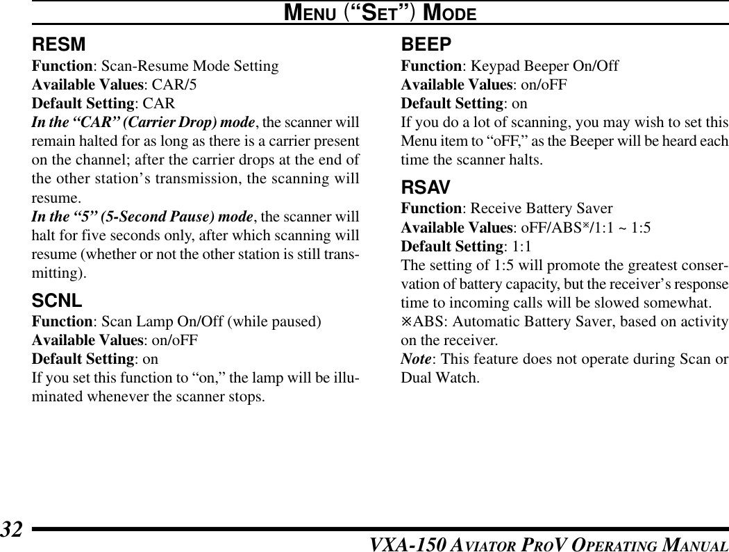
![VXA-150 AVIATOR PROV OPERATING MANUAL 21OPERATIONReceive Battery Saver SetupAn important feature of the VXA-150 is its ReceiveBattery Saver, which “puts the radio to sleep” for atime interval, periodically “waking it up” to checkfor activity. If somebody is talking on the channel,the VXA-150 will remain in the “active” mode, thenresume its “sleep” cycles. This feature significantlyreduces quiescent battery drain, and you may changethe amount of “sleep” time between activity checksusing the Menu System:rPress the [F] key, then press the CHANNEL se-lector knob to activate the Menu (“SET”) mode.rRotate the CHANNEL selector knob to selectMenu Item “RSAV.”rPress the CHANNEL selector knob to enable ad-justment of this Menu item.rRotate the CHANNEL selector knob to selectthe desired “duty cycle” (receive:sleep). The se-lections available are 1:1, 1:2, 1:3, 1:4, 1:5, andABSø or oFF. The default value is 1:1.rWhen you have made your selection, press theCHANNEL selector knob to save the new set-ting, and then press the PTT key exit to normaloperation.øABS: Automatic Battery Saver, based on activityon the receiver.The setting of 1:5 will promote the greatest conser-vation of battery capacity, but the receiver’s responsetime to incoming calls will be slowed somewhat.Note: This feature does not operate during Scan orDual Watch.](https://usermanual.wiki/Yaesu-Musen/VXA-150/User-Guide-171522-Page-23.png)
![VXA-150 AVIATOR PROV OPERATING MANUAL22MEMORY OPERATIONThe VXA-150 provides 50 user-programmable“Main” memories, labeled “CH-001” through “CH-050,” and up to 100 pre-programmed memories, des-ignated “Book” Memories. The “” icon appearswhen “Book” Memory Mode is activated.The Main memories and “Book” Memories can beassigned alpha-numeric names of up to eight charac-ters.Memory System OperationThe VXA-150’s Main Memory system allows theuser to store, label, and recall channel frequencieswhich you may want to use frequently. You may storeVFO frequencies, Book Memory frequencies, and/or Weather Channel frequencies (USA version only)into the Main Memory system.Memory StoragerSelect the desired frequency in the VFO mode,or recall the Book Memory channel or Weatherchannel to be stored in the Main Memory.rPress and hold the [MW (SPL.W)] key for 2seconds. The display will indicate “CH-” and achannel number will blink on the LCD.rWithin five seconds of pressing the [MW(SPL.W)] key, rotate the CHANNEL selectorknob to select the desired memory channel num-ber for storage.In order to prevent writing over memory chan-nels, a bar will appear under the hyphen (locatedbetween “CH” and the channel number) to indi-cate a vacant memory channel.rNow press and hold in the [MW (SPL.W)] keyfor 2 seconds; you will now see “ - - - - - - - - ” on theLCD. To attach an alpha/numeric name (label)to the memory, proceed to the next step; other-wise press and hold [MW (SPL.W)] for 2 sec-onds to save the entry and exit.rTo label a memory with an alpha/numeric name,the next step is to use the CHANNEL selectorknob to select any of the 48 available characters(including letters, numbers, and special symbols).](https://usermanual.wiki/Yaesu-Musen/VXA-150/User-Guide-171522-Page-24.png)
![VXA-150 AVIATOR PROV OPERATING MANUAL 23When the desired first character appears, pressthe CHANNEL selector knob momentarily tomove on to the next character.rSelect succeeding characters in the same man-ner, pressing the CHANNEL selector knob mo-mentarily after each selection.rAfter entering the entire name (eight charactersmaximum), press the [MW (SPL.W)] key for 2seconds to save all data for the channel and exit.Note: If you have stored a Weather Channel, the“WX-001~ WX-010” labels utilize the alphanu-meric memory, and other labels may not be stored.Recalling the MemoriesrPress the CHANNEL selector knob, repeatedlyif necessary, until “MR” (Memory Recall) ap-pears on the display. In the MR mode, you willsee “CH-” and the previously selected channelnumber appearing on the LCD.rRotate the CHANNEL selector knob to selectthe desired memory channel.rYou may change the title structure of the Memorydisplay type among:1. Channel Indication (sequential Channel Number,e.g. CH-001, CH-002, etc.);2. Frequency Indication (e.g. 122.500); or3. Alphanumeric Label (e.g. LAX FSS).rTo change the Memory display title, press the[ ()] key repeatedly, if necessary, until youget the desired display title structure.rTo exit the Memory mode, press the CHANNEL se-lector knob momentarily to return to the VFO mode.Note: In the “Book” Memory mode, you can changememory channels in 10 channel steps: press the [F]key momentarily, then rotate the CHANNEL selec-tor knob. The “” icon will show at the right edgeof the display when the 10 channel step tuning modeis active. Press the [F] key once more to resume nor-mal channel selection in 1 channel steps.MEMORY OPERATIONAlpha-tag Charactors)!@#$%^&*(ABCDEFGHIJKLMNOPQRSTUVWXYZ<>+; : ¥`y[|"](https://usermanual.wiki/Yaesu-Musen/VXA-150/User-Guide-171522-Page-25.png)
![VXA-150 AVIATOR PROV OPERATING MANUAL24SCANNING OPERATIONThe VXA-150 allows you to scan automatically inthe VFOø1, Main Memory, “Book” Memory, orWeather Channelø2 modes. It pauses on signals en-countered, so you can talk to the station(s) on thatfrequency, if you like.ø1: In the VFO mode, the automatic scanner is onlyavailable in the COM band (118.000 - 136.975MHz); when the scanner reaches the uppermost fre-quency in the COM band, it will revert to the bot-tom end of the COM band and repeat the scanningprocess until you cancel the scanning process.ø2: USA version only.If you wish to scan in the NAV band (108.000 -117.975 MHz), you can do so manually, as describedat the right.Scanning operation is basically the same in each ofthe above modes.rPress the [SCAN (DW)] key momentarily to startthe automatic scanner upward (toward a higherfrequency or a higher channel number).rWhen the scanner encounters a signal, scanningpauses and the radio remains on that channel untilone second after the signal disappears, afterwhich scanning will resume.rWhile the scanner remains paused on a frequency,the decimal point of the frequency display blinks.The display and keypad will be illuminated un-less the Scan Lamp Feature is turned off.rTo change the scan direction, turn the CHAN-NEL selector knob one click in the opposite di-rection.rTo stop the automatic scanner, press the PTT switchor the CHANNEL selector knob momentarily. Youmay also press [SCAN (DW)] key again.The VXA-150’s automatic scanner is not operationalin the NAV band (108.000 - 117.975 MHz), becausethe NAV stations (ILS, etc.) transmit constantly(thereby causing the scanner to stop repeatedly).However, you can scan manually in the NAV band,per the following procedure:rPress and hold the [SCAN (DW)] key to startthe manual scanner. Scanning will continue aslong as the key is depressed.rRelease the [SCAN (DW)] key to stop themanual scanner immediately.](https://usermanual.wiki/Yaesu-Musen/VXA-150/User-Guide-171522-Page-26.png)
![VXA-150 AVIATOR PROV OPERATING MANUAL 25SCANNING OPERATIONChannel-Skip ScanningContinuous-carrier stations like ATIS (AutomaticTerminal Information Service) or Weather Broadcaststations inhibit scanner operation. Since these sta-tions are always active, the scanner will be haltedrepeatedly on their channels. Such channels can beset to be “skipped” during scanning, if you like, soas not to interfere with automatic channel scanning:rRecall the Memory Channel to be skipped dur-ing scanning.rPress [F] à [9 (SKIP)]. The “SKIP” icon willappear in the lower right corner, indicating thatthe channel is to be ignored during scanning.rYou can also designate a channel to be skippedwhile scanning. When the receiver is halted on achannel that you wish to skip, press and hold the[SCAN (DW)] key for 2 seconds (the “SKIP”icon will appear next to the channel to beskipped).rLater, to re-enable the memory channel for scan-ning, repeat the first two steps. The “SKIP” iconwill disappear by the channel you have just re-enabled.Note: A memory set to be “skipped” is still acces-sible for manual memory selection using the CHAN-NEL selector knob.](https://usermanual.wiki/Yaesu-Musen/VXA-150/User-Guide-171522-Page-27.png)
![VXA-150 AVIATOR PROV OPERATING MANUAL26DUAL WATCH OPERATIONThe Dual Watch feature automatically checks foractivity on a “priority” channel* while you are oper-ating on another channel. During Dual Watch opera-tion, the current channel and the Priority channel willeach be polled for a 500 ms interval, as the VXA-150 looks for activity on each channel.rTo start Dual Watch, press [F] à [SCAN (DW)].The “DW” icon will appear on the display.rWhile receiving on the “current” channel (notthe Priority channel), you may push the PTTswitch at any time to transmit on that channel.rWhen a signal is received on the Priority chan-nel, operation immediately shifts to the Prioritychannel, the “DW” icon will blink, and the dis-play and keypad will become illuminated.While receiving on the priority channel, if youmomentarily press the PTT switch, Dual Watchwill be disabled. You may then transmit on thePriority Channel.rTo stop Dual Watch, press [F] à [SCAN (DW)].rIf you wish, you may use both the Dual Watchand Scan features simultaneously. To do this, startthe Dual Watch first, then start the Scanner.* The “Priority” Channel is defined as the last-usedMemory Channel (when using the VFO mode) orMemory Channel 1 (when using the Main Memoryor Book Memory modes).](https://usermanual.wiki/Yaesu-Musen/VXA-150/User-Guide-171522-Page-28.png)
![VXA-150 AVIATOR PROV OPERATING MANUAL 27PRIORITY DUAL WATCH OPERATIONSimilar to Dual Watch operation (described on pre-vious page), Priority Dual Watch is an enhanced ver-sion which includes the following additional features:lThe receiving time interval (ratio) between thecurrent channel and the Priority channel may becustomized via the Menu mode, item PRTM. Seepage 30 for details.lIrrespective of which channel is currently beingreceived, when the PTT button is pushed trans-mission will always occur on the Priority chan-nel.Before initiating Priority Dual Watch, Menu itemDWMD must be set to the “Priority” mode (insteadof “Dual Watch”). See page 30 for details.rTo start Priority Dual Watch, press [F] à [SCAN(DW)]. The “DW” icon will appear on the dis-play.rWhile receiving on the “current” (non-Priority)channel, pressing the PTT button once causesthe radio to switch to the Priority channel andcancels Dual Watch. Press the PTT button againto transmit on the Priority channel.rWhen a signal is received on the Priority chan-nel, reception immediately shifts to the Prioritychannel, the “DW” icon will blink, and the dis-play and keypad will become illuminated unlessthe Scan Lamp Feature is turned off.While receiving on the priority channel, if youmomentarily press the PTT switch, Priority DualWatch will be disabled. You may then transmiton the Priority Channel.rTo stop Priority Dual Watch, press [F] à [SCAN(DW)].](https://usermanual.wiki/Yaesu-Musen/VXA-150/User-Guide-171522-Page-29.png)
![VXA-150 AVIATOR PROV OPERATING MANUAL28The split operation feature allows you to transmit acall to a Flight Service Station using the COM bandfrequencies, while receiving a NAV band station (suchas the ATIS, AWOS etc.). NAV band stations equippedwith this capability typically are shown, on naviga-tion charts, with the voice calling frequency in pa-renthesis above the navigation frequency.Programming a Transmit FrequencyrPress the CHANNEL selector knob, repeatedlyif necessary, to select the VFO mode.rSet a NAV band (108.000 - 117.975 MHz) fre-quency using the CHANNEL selector knob orkeypad.rPress [F] à [MW (SPL.W)]. The “SPL” iconwill blink, and the transmit frequency will ap-pear on the display.rNow set your radio’s transmit frequency, wherethe Flight Service Station will be listening forcalls, using the CHANNEL selector knob or key-pad.rPress and hold in the [MW (SPL.W)] key for 2seconds to save the transmit frequency and re-turn to the NAV band frequency.SPLIT OPERATIONNote: You have now stored the separate transmit fre-quency, but you have not yet activated the split-fre-quency function; go on to the next section.Operating in the Split ModerIt is assumed that you have already set the de-sired NAV band station’s frequencies per theabove instructions.rPress [F] à [7 (SPL)] to turn on the “Split”function. The “SPL” icon will appear on the dis-play.rPress and hold in the PTT switch to transmit onthe split transmit frequency.rRelease the PTT switch to return to the receivemode.rTo disable the “Split” function, press [F] à [7(SPL)] again.Note: A split frequency can be programmed into eachmemory channel independently. Set a transmit fre-quency before programming the memory channel, ifdesired. The split function on/off setting can also beprogrammed into a memory channel.](https://usermanual.wiki/Yaesu-Musen/VXA-150/User-Guide-171522-Page-30.png)
![VXA-150 AVIATOR PROV OPERATING MANUAL 29FIELD PROGRAMMING MODEThe VXA-150’s Book Memories also allow the userto store, label, and recall channel frequencies whichyou may want to use frequently while the VXA-150is in the Field Programming mode.Memory Storage into the Book MemoryrPress and hold the PTT and LAMP switcheswhile turning the radio on, to activate the FieldProgramming Mode.rSelect the desired frequency to be stored in theBook Memory.rPress and hold the [MW(SPL.W)] key for 2 sec-onds. The display will indicate “BOOK-” and achannel number will blink on the LCD.rWithin five seconds of pressing the[MW(SPL.W)] key, rotate the CHANNEL se-lector knob to select the desired memory chan-nel number for storage.rNow press and hold in the [MW(SPL.W)] keyfor 2 seconds; you will now see “ - - - - - - - - ” on theLCD. To attach an alpha/numeric name (label)to the memory, proceed to the next step; other-wise press and hold the [MW(SPL.W)] key for2 seconds to save the entry and exit.rTo label a memory with an alpha/numeric name,the next step is to use the CHANNEL selectorknob to select any of the 48 available characters(including letters, numbers, and special symbols).When the desired first character appears, pressdown on the CHANNEL selector knob momen-tarily to move on to the next character.rSelect succeeding characters in the same man-ner, pressing down on the CHANNEL selectorknob momentarily after each selection.rAfter entering the entire name (eight charactersmaximum), press the [MW(SPL.W)] key for 2seconds to save all data for the channel.rTurn the radio off, then turn the radio back onagain to begin normal operation.](https://usermanual.wiki/Yaesu-Musen/VXA-150/User-Guide-171522-Page-31.png)
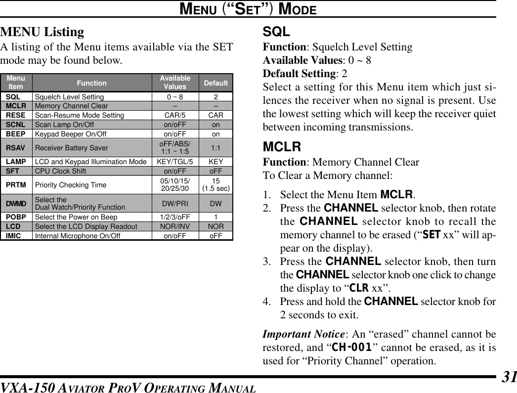
![VXA-150 AVIATOR PROV OPERATING MANUAL30MENU (“SET”) MODEThe Menu system allows certain aspects of yourradio’s configuration to be customized for your per-sonal operating convenience. We do not recommendthat any of the default settings be changed, however,until you are thoroughly familiar with the operationof the VXA-150.1. Press the [F] key, thenpress the CHANNELselector knob to activatethe Menu (“SET”)mode.2. Rotate the CHANNELselector knob to selectthe Menu item (feature)you wish to view and/ormodify.3. Once you have selectedthe desired Menu Item,press the CHANNELselector knob once toview the current settingfor the item.4. Rotate the CHANNELselector knob to changethe setting of the item(ON to OFF, etc.).5. Press the CHANNELselector knob to saveyour new setting.6. If you need to changemore than one Menuitem, repeat steps 2 - 5.7. Press the PTT switch toexit the Menu (“SET”)mode.](https://usermanual.wiki/Yaesu-Musen/VXA-150/User-Guide-171522-Page-32.png)
![VXA-150 AVIATOR PROV OPERATING MANUAL 33LAMPFunction: LCD and Keypad Illumination ModeAvailable Values: KEY/TGL/5Default Setting: KEYIn the “KEY” mode, the lamp will be activated for 5seconds when a front panel key is pressed.In the “TGL” mode, the LAMP switch toggles thelamp on and off.In the “5” mode, the LAMP switch activates the lampfor 5 seconds.SFTFunction: CPU Clock ShiftAvailable Values: on/oFFDefault Setting: oFFThis function is only used to move a spurious response“birdie” should it fall on a desired frequency. Consult yourVertex Standard dealer for details regarding this function.PRTMFunction: Priority Checking TimeAvailable Values: 05/10/15/20/25/30 (x0.1 sec)Default Setting: 15 (1.5 seconds)This Menu item allows you to define how often thePriority Channel will be checked for activity.Note: The Dual Watch Polling time is 500 mS (fixed).MENU (“SET”) MODEDWMDFunction: Select the Dual Watch/Priority FunctionAvailable Values: DW/PRIDefault Setting: DWIn the DW mode, the VXA-150 will activate the DualWatch feature when you press [F] à [SCAN (DW)].In the PRI mode, the VXA-150 will activate the Pri-ority feature when you press [F] à [SCAN (DW)].POBPFunction: Select the Power on BeepAvailable Values: 1/2/3/oFFDefault Setting: 1LCDFunction: Select the LCD Display ReadoutAvailable Values: NOR/INVDefault Setting: NORIMICFunction: Internal Microphone On/OffAvailable Values: on/oFFDefault Setting: oFFWhen operating the VXA-150 with External Avia-tion Headset (using supplied CT-60 Headset Cable)or optional MH-44A4B Speaker Microphone while thisfunction set to “oFF.”](https://usermanual.wiki/Yaesu-Musen/VXA-150/User-Guide-171522-Page-35.png)