Yaesu Musen VXR-7000U UHF-FM Desktop Repeater User Manual K66VXR 7000U OperatingManual
Yaesu Musen Co., Ltd. UHF-FM Desktop Repeater K66VXR 7000U OperatingManual
UserManual.wiki
>
Yaesu Musen
>
VXR 7000U User Manual
Manual
Navigation menu
Upload a User Manual
Namespaces
Wiki Guide
HTML
PDF
Info
Views
User Manual
Discussion / Help
Navigation
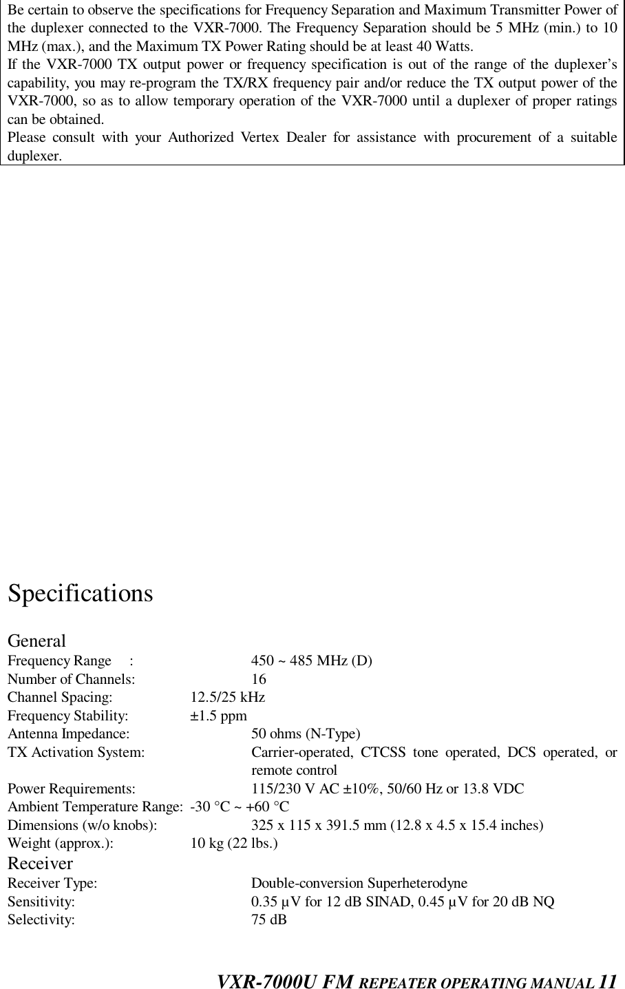
![VXR-7000U FM REPEATER OPERATING MANUAL 3 Press this button again to clear the message on the ANI display, and turn off the LCD backlight.Rear Panel1: EXT SP JackThis 3.5-mm, 2-pin jack provides variable audio output for an external speaker. The audio outputimpedance at this jack is 4ohms ~ 16ohms and level varies according to the setting of the frontpanel’s VOL control.2: TX Antenna JackThis N-type coaxial jack provides the transmitting output signal for connection to the transmittingantenna or TX jack on the duplexer, if used. The output impedance requirement is 50 W.3: RX Antenna JackThis N-type coaxial jack accepts the receiver input signal from the receiving antenna or RX jack onthe duplexer, if used. The input impedance requirement is 50 W.4: ACC JackThis DB-25 connector provides a data interface between the microprocessor in the VXR-7000 andperipheral devices (such as the VX-TRUNK Unit).5: LINE JackThis 8-pin modular jack is used for remote control. It provides TX and RX audio, TX keying, andsquelch status output. The TX and RX audio impedance is 600 W.6: GND TerminalFor best performance and safety, the GND terminal should be connected to a good earth ground usinga short, heavy, braided cable.7: AC JackThis receptacle accepts the AC power cord, which should be connected to the AC mains supply orwall outlet. The AC line voltage must match that for which the repeater is wired.8: BATT TerminalThese terminal posts accept 12~ 15 VDC for operating the repeater from a battery or other DCsource. When operating from AC mains, a small trickle current is present at these terminals tomaintain battery charge. A battery rated for 12 volts, 55 Ah (minimum) is recommended for short-term emergency/backup operation.ACC Connector PortThe VXR-7000 repeater is provided with a 25-pin DB-25F female connector for interconnections toaccessories. Use a DB-25M 25-pin male connector to connect accessories to the repeater. The pins onthe accessory connector are explained in detail as follows:Pin 1: GND Chassis ground for all logic levels and power supply return.Pin 2: +13.8 V [Power Supply]This pin provides 13.8 Volts, 1.0 A, regulated DC from the repeater supply. Use a 1 A fuse in theexternal device’s DC line to prevent damage to the repeater.Pin 3: TX AF IN [Analog Transmitter Input] (Voice Band: 300 ~ 3,000 Hz)Input impedance is approx. 600 W. This audio is injected before the splatter filter stage, so excesssignal input levels are clipped. Use shielded cable to connect to this pin, and connect the shield to GND.Pin 4: TONE IN [Transmitter Input] (Sub-audible Band: 6 ~ 250 Hz) The input is high impedance (approx. 22 ?W). Injecting too high a voltage here causes over-deviationof CTCSS or DCS, degrading performance. Use shielded cable to connect to this pin, connecting theshield to GND.](https://usermanual.wiki/Yaesu-Musen/VXR-7000U/User-Guide-78665-Page-4.png)
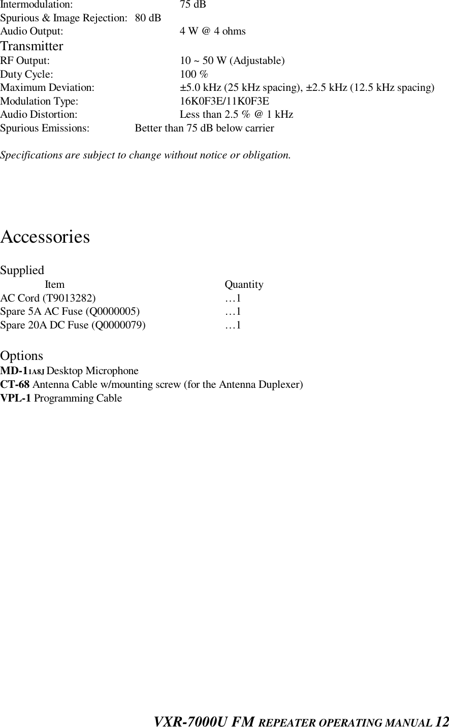
![VXR-7000U FM REPEATER OPERATING MANUAL 4Pin 5: N.C. (No connection.)Pin 6: DISC OUT [Analog Output] (Wide-Band: 0 ~ 3,000 Hz)Received signals with standard deviation produce approx. 1 V p-p audio at this pin. The outputimpedance is approx. 600 W, and is extracted before the de-emphasis and squelch circuitry. Useshielded cable to connect to this pin, and connect the shield to GND.Pin 7: GND Chassis ground for all logic levels and power supply return.Pin 8: RSSI [Analog Output]A DC voltage proportional to the strength of the signal currently being received (Receiver SignalStrength Indicator) is provided on this pin. This low impedance output is generated by the receiver IFsub-system and buffered by an internal op-amp. Typical voltages are graphed as follows:Pin 9: COAX. SW [Logic Output (Active Low)]This output is intended for controlling an external coaxial switching relay. It is an open collectoroutput, which can sink approx. 10 mA when active. This signal only switches if the repeater has beenprogrammed for “SIMPLEX” mode. If programmed for “DUPLEX” the signal remains open (highimpedance) at all time.Pin 10: N.C. (No connection.)Pin 11: NSQ DETThis is an open-collector, active-low output capable of sinking about 10 mA. It indicates that thereceiver squelch is open. If the squelch control is properly set, this indicates a carrier on the receiverchannel.Pin 12: EXT PTTThis input is internally pulled up to 5 VDC. When pulled low by an external device, it keys therepeater transmitter while the repeater is operating in the “BASE” mode. Avoid voltage in excess of5 V on this pin, or internal damage to the microprocessor on the repeater CNTL Unit may result.Pin 13: GND Chassis ground for all logic levels and power supply return.Pin 14: GNDChassis ground for all logic levels and power supply return.Pin 15: N.C. (No connection.)Pin 16, 17, 18, & 19: REMOTE CH DATA [Logic Inputs D3, D2, D1, and D0] (Active Low)These inputs are internally pulled up to 5-V DC. When pulled low by an external device, they selectone of the 16 pre-programmed repeater-operating channels. The logic truth table below shows thecombinations for selecting all 16 channels. In the truth table, “1” represents no connection, and “l”represents a ground connection on the pin. The channel selection logic is not inhibited while thetransmitter is keyed: the repeater will change frequency when instructed, even while transmitting.Avoid voltage in excess of 5 V on these pins or internal damage to the microprocessor on the repeaterCNTL Unit may result.Channel Pin 16(D3) Pin 17(D2) Pin 18(D1) Pin 19(D0)1 1 1 1 12 1 1 1 03 1 1 0 14 1 1 0 05 1 0 1 16 1 0 1 07 1 0 0 1](https://usermanual.wiki/Yaesu-Musen/VXR-7000U/User-Guide-78665-Page-5.png)
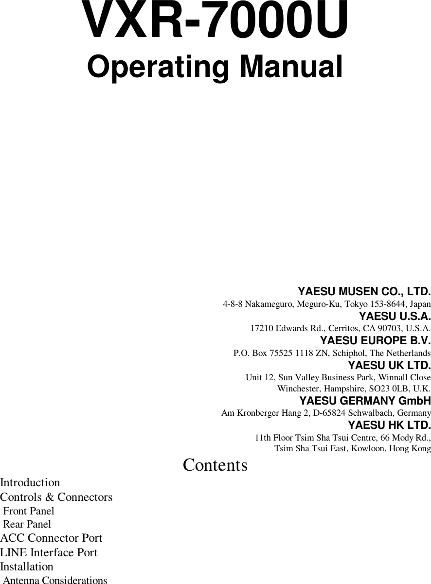
![VXR-7000U FM REPEATER OPERATING MANUAL 58 1 0 0 09 0 1 1 110 0 1 1 011 0 1 0 112 0 1 0 013 0 0 1 114 0 0 1 015 0 0 0 116 0 0 0 0Pin 20: GND Chassis ground for all logic levels and power supply return.Pin 21: A-OUTPUT [Logic Output] (Active Low)This open collector logic output is pulled low when the front panel’s ACCESSORY key is turned on.It can sink approx. 10 mA when active.Pin 22: RXD LOW [Digital Output for DATA Communications] (300 ~ 3,000 Hz)This pin is an output for low speed receiving data signals, with the data being extracted after the de-emphasis and low pass filter stages.Pin 23: RXD HI [Digital Output for DATA Communications]This pin is an output for high speed receiving data signals, with the data being extracted immediatelyafter the discriminator prior to any de-emphasis).Pin 24: TXD LOW [Digital Input for DATA Communications] (300 ~ 3,000 Hz)This pin is intended to be used as a low speed digital data signal input to the repeater. This digitaldata signal is injected before transmitter pre-emphasis and limiting stage, so excess signal inputlevels are clipped.Pin 25: TXD HI [Digital Input for the DATA Communications]This pin is intended to be used as a high-speed digital data signal input to the repeater. This digitaldata signal is injected after transmitter splatter filter stage.CLINE Interface PortThe VXR-7000 is provided with an 8-pin modular jack for line interfacing applications. A WesternElectric modular-type RJ45 plug should be used to connect to this jack. The LINE jack pin-out isshown below.Note that there are both 4-line and 8-line types of modular plugs. If a 4-line modular plug is used,only the LINE OUT and LINE IN connections will be made. An 8-line plug is required to access alllines. In accordance with standard telecommunications interface, the line connections on the LINEinterface jack are impedance balanced, and are described as follows.Pins 1 & 2: [RX SQ (+), RX SQ (–)]An opto-isolator is provided to facilitate E (EAR) signaling. The opto-isolator comes on when asignal exceeding the receiver squelch appears on the receiver channel (with correct CTCSS tone orDCS code, if enabled). The RX SQ(Œ) pin is the emitter, and RX SQ(+) is the collector.Pins 3 & 4: [LINE IN (TX Line Audio)]Analog signals between 300 and 3000 Hz supplied to this pair are fed to the transmitter when therepeater is set to the BASE mode (the REPEATER LED is turned off) and keyed either by the TXKEY input signal (see below), or by the EXT PTT signal on pin 12 of the rear panel’s ACC jack.Standard deviation is obtained with a line level of -10 dBm.Pins 5 & 6: [LINE OUT (Rx Line Audio)]Receiver audio is available from this pair, subject to internal CTCSS or DCS decode if the receivedsignal strength is above the squelch threshold.](https://usermanual.wiki/Yaesu-Musen/VXR-7000U/User-Guide-78665-Page-6.png)
![VXR-7000U FM REPEATER OPERATING MANUAL 6As shipped from the factory, a 1-kHz receiver signal with standard deviation gives Œ10 dBm on theline, but this can be varied by VR4002 and S4001 (on the repeater’s CNTL Unit).Pins 7 & 8 [TX KEY (+), TX KEY (-)]An opto-isolator is provided to facilitate M (MIC) signaling. That is, a voltage presented to thesepins turns on the opto-isolator and keys the transmitter.The TX KEY (+) pin is the anode of the opto-isolator, and RX SQ(Œ) is the cathode of the opto-isolator.InstallationAntenna ConsiderationsRepeater operation without a duplexer requires that two antennas be installed, one for receiving andone for transmitting, so that the receiving antenna does not absorb energy from the transmittingantenna. There are a number of ways to do this, depending on the TX/RX frequency separation, andon the locations available for antenna mounting. If a duplexer is used, a single antenna suffices forboth transmitting and receiving. If using a reduced-size duplexer, a six-cavity model (minimum) isrecommended. Vertex Standard recommends the use of the duplexer. For further details, contact yourVertex Standard dealer.Regardless of the above choice, it is of paramount importance that the antenna(s) be mounted as highand in the clear as possible, preferably within line-of-sight to all repeater users. Furthermore, lossesin the feedline(s) must be minimized, so the feedline(s) should be high quality, and as short aspossible. If a long feedline is necessary, use coaxial “hardline”, cable to reduce losses.Repeater antennas should have impedance of 50 ohms at the operating frequency. When separatereceives and transmits antennas are used, high-Q narrow-band types may serve to minimizeinteraction. However, when a single antenna is used with a duplexer, it should be a low-Q wide-bandtype.NEVER TRANSMIT WITHOUT HAVING ATRANSMIT ANTENNA CONNECTED TOTHE TX ANTENNA JACK OF THEREPEATER.AC Power Supply Voltage SelectionEach repeater is wired for a particular AC mains voltage between 100 and 253 VAC. This should beindicated by a label near the AC jack on the rear panel. If no label is present, or if the AC voltage onthe label is different from the local AC line, check the wiring inside the Switching Regulator Unit ofthe repeater, and change the connections (and label) if necessary, as shown next page.Changing the AC input voltage wiring also requires changing the fuse on the FILTER Unit if thevoltage is changed from 100 VAC (100-127 VAC) to 200 VAC (207-253 VAC), or vice-versa. Use a5-amp fuse for 100 VAC, or a 3-amp fuse for the 200 VAC.DC Power Supply BackupFor uninterrupted operation during power failures, a 12-volt rechargeable type battery (55-Ah ormore recommended) may be connected to the BATT terminal posts on the rear panel. While therepeater is operating from the AC source, a slight charging current will maintain battery charge. In](https://usermanual.wiki/Yaesu-Musen/VXR-7000U/User-Guide-78665-Page-7.png)
![VXR-7000U FM REPEATER OPERATING MANUAL 8Now connect the VPL-1 Connection Cable to the computer’s serial port and the VXR-7000.Then it will be safe to restart the computer; turning off the equipment during interconnection avoidsthe potential for damage to the electronics caused by voltage spikes.Insert the distribution diskette into your 3.5” drive (after booting DOS), and make a copy of thediskette; use the distribution diskette for archive purposes, and use the disk copy for programming.Place the CE-27 (copy) diskette into your 3.5” drive (usually “Drive A”), and log onto this drive bytyping “A:[Enter]”, then load the contents of the CE-27 diskette into a directory named CE27, usingthe COPY command (e.g. “COPY A:\*.* C:\CE27”).Now type “CE27 [Enter]” to start the program. The introductory screen will appear, and you maypress any key to enter the main screen.Choose the “Help” contents option (F1) from the program’s Menu for assistance with channelprogramming or setting of parameters.Important Note!Do not work directly with the CE-27programming diskette. Make a copy of it anduse the copy when programming the VXR-7000. Keep it and the original distributiondiskette in a safe place in case you need tomake another copy of it later.Channel Data ItemsCh: Channel NumberThis 2-digit number (01 - 16) is used to identify the channel. Channel numbers occur in sequence, andtheir order can not be changed.Rx Freq.: Edit Receive (or simplex) FrequencyUse the [0] - [9] keys to enter the desired channel frequency directly, and press the [ENTER] key.CTCSS Decoders: Toggle CTCSS Decoder ON/OFF, sets CTCSS FrequencyPress the [SPACE] bar to toggle the CTCSS Decoder ON or OFF, or press the [ENTER] key todisplay the TONE SELECT window, from which you may select a CTCSS frequency using the[Arrow] key; press [ENTER] again to accept the selected tone, or press [ESC] key to cancel.DCS Decoders: Toggle DCS Decoder ON/OFF, sets DCS Code #Press the [SPACE] bar to toggle the DCS Decoder ON or OFF, or press the [ENTER] key to displaythe CODE SELECT window, from which you may select a DCS code using the [Arrow] key; press[ENTER] again to accept the selected code, or press the [ESC] key to cancel.W/N: Wide/Narrow Channel SpacingThis function selects the channel spacing environment in which the VXR-7000 operates.W (Wide) = 25 kHz Channel Spacing, ±5 kHz Deviation.N (Narrow) = 12.5 kHz Channel Spacing, ±2.5 kHz Deviation.Press the [SPACE] bar to select the desired channel spacing environment.Clk Sft: Enable/disable the CPU Clock ShiftThis function is only used to move a spurious response “birdie,” should it fall on a desired operatingfrequency.NSQ Mode: Noise Squelch ModeThis command adjustment mode for the Squelch threshold level.User = The squelch threshold level is fixed via a programmable parameter (NSQ LV: 0[min.] ~ 255 [max.]).Prpgm = The squelch threshold level can be adjusted via front panel SQL knob temporarily.Press the [SPACE] bar to select the desired NSQ Mode.NSQ LV: Noise Squelch threshold levelUse the [0] - [9] keys to enter the desired Squelch threshold level directly, and press the [ENTER] key.](https://usermanual.wiki/Yaesu-Musen/VXR-7000U/User-Guide-78665-Page-9.png)
![VXR-7000U FM REPEATER OPERATING MANUAL 9This is an arbitrary adjustment value, which must be set experimentally. Available values are 0 (min.)~ 255 (max.).Court Blip: Courtesy BlipWhen this parameter is set to “on,” this function causes the VXR-7000 to send out a “blip” on theportable radio frequency each time the portable radio is unkeyed. This provides audible confirmationto the user that the VXR-7000 was able to receive the transmission from the portable.Rev Bst: Reverse Burst.When this parameter is set to “on,” the CTCSS tone signal’s phase is inverted just before the repeaterturns to receive. This allows the portable/mobile station’s CTCSS Decoder to begin switching off, thusreducing the transition time required.DCS Typ: DCS FormatThis command is effective only when DCS is chosen for squelch control.A = “Normal” DCSB = “Inverted” (complement) DCSPress the [SPACE] bar to select the desired DCS Type.DDec Type: DCS Decoder TypeThis command selects the manner in which DCS is to be decoded.Fixed = Decodes the type selected in above parameter (DCS Typ: Normal or Inverted).Auto = Decodes both types (Normal and Inverted).Press the [SPACE] bar to select the desired DCS Decoder Mode.Multi Tone: Enable/disable Multi Tone OperationPress the [SPACE] bar to toggle Multi Tone Operation ON or OFF, or press the [ENTER] key todisplay the MULTI TONE SELECT window, from which you may select a CTCSS tone or DCS codeusing the [Arrow] key; press [ENTER] again to accept the selected code, or press the [ESC] key tocancel.CWID ANI/ENI: Select the Identicate modePress the [SPACE] bar to toggle among CW ID, ANI/ENI or OFF. The CW ID or ANI/ENI featuremust be enabled via the dealer programming.Action Mode: Select the repeater operating modePress the [SPACE] bar to toggle between Duplex operation and Simplex operation.TX Freq.: Edit Transmit FrequencyUse the [0] - [9] keys to enter the desired channel frequency directly, and press the [ENTER] key.CTCSS Encoders: Toggle CTCSS Encoder ON/OFF, sets CTCSS FrequencyPress the [SPACE] bar to toggle the CTCSS Encoder ON or OFF, or press the [ENTER] key todisplay the TONE SELECT window, from which you may select a CTCSS frequency using the[Arrow] key; press [ENTER] again to accept the selected tone, or press the [ESC] key to cancel.DCS Encoders: Toggle DCS Encoder ON/OFF, sets DCS Code #Press the [SPACE] bar to toggle the DCS Encoder ON or OFF, or press the [ENTER] key to displaythe CODE SELECT window, from which you may select a DCS code using the [Arrow] key; press[ENTER] again to accept the selected code, or press the [ESC] key to cancel.Base TOT: Enable/disable the Time-Out Timer while operating in the “BASE” station modePress the [SPACE] bar to toggle the Base TOT feature between yes and no.The TOT time is determined via dealer programming.Base Guard: Enable/disable the Base Guard FeatureWhen this parameter is set to “yes,” the transmitter will be inhibited for a few seconds before therepeater (in the “BASE” station mode) turns to receive.The inhibit time is determined via dealer programming.LOUT: Select the Lock Out FeaturePress the [SPACE] bar to toggle the Lock Out Feature among BCLO, BTLO, or off. BCLO inhibitstransmitting while there is carrier present. BTLO inhibits transmitting while there is carrier presentunless there also is a valid tone present; this allows the operator to respond to a tone-controlled](https://usermanual.wiki/Yaesu-Musen/VXR-7000U/User-Guide-78665-Page-10.png)
![VXR-7000U FM REPEATER OPERATING MANUAL 10station, while maintaining the “Lock-Out” control with respect to non-tone-controlled signals.TX Pwr: Transmitter Power Output SelectionThis parameter selects the desired power output from the VXR-7000 on the current channel. Theavailable values are HIGH and LOW.Press the [SPACE] bar to select HIGH or LOW.TOT Mute: Enable/disable the TOT (Time-Out Timer) beepWhen this parameter is set to “on,” an alert beep will be sent before the repeater turns itself off.RptTOT Use: Enable/disable the Time-Out Timer while operating in the repeater modePress the [SPACE] bar to toggle the Repeater TOT feature between yes and no.The TOT time is determined via dealer programming.RptTOT Beep: Enable/disable the TOT beepPress the [SPACE] bar to toggle the TOT beep between yes or no.When this parameter is set to “yes,” the alert beep will be transmitted on the air before the repeaterturns itself off.RPT HT: Enable/disable the Repeater Hang-up TimerPress the [SPACE] bar to toggle the Repeater Hang-up Timer between yes and no.When this parameter is set to “yes,” transmit the alert beep on the air before the repeater turns it selfoff.The Hang-up time is determined via dealer programming.RPT GT: Enable/disable the Repeater GuardWhen this parameter is set to “yes,” the transmitter inhibit few second before the repeater turns toreceive.The inhibit time is determined via dealer programming.Duplexer InstallationPlease refer to the operating manual for your Duplexer for details regarding maximum power input,TX/RX connector locations, etc) before installing the Antenna Duplexer.1. Remove the 14 screws affixing the top and bottom covers of repeater, and remove the covers(Figure 1).2. Turn the repeater upside down.3. Referring to Figure 2, remove the upper screw in either side of the front panel, and loosen thelower screw in either side of the front panel, then slide the front panel forward slightly.4. Remove the coaxial cables connected to the TX and RX antenna jacks of the repeater.5. Mount the duplexer to the bottom side of the repeater, using the four screws supplied with theoptional Antenna Cable CT-68 (Figure 3).6. Connect the optional Antenna Cable CT-68 between the TX antenna jack of the repeater andANT (center) jack of the duplexer.7. If your repeater’ TX/RX frequency relationship is “upper shift” type (TXf > RXf), connect thecoaxial cable from the RX Unit to the LOW PASS jack of the duplexer and connect the coaxialcable from the PA Unit to the HIGH PASS jack of the duplexer.If your repeater’s TX/RX frequency relationship is “lower shift” type (TXf < RXf), connect thecoaxial cable from the RX Unit to the HIGH PASS jack of the duplexer and connect the coaxialcable from the PA Unit to the LOW PASS jack of the duplexer.Note: Route the TX coaxial cable from the PA Unit as far as possible from the RX coaxial cablefrom the RX Unit.8. Duplexer installation is now complete. Replace the front panel back into place, and replace the topand bottom covers.Important Note!](https://usermanual.wiki/Yaesu-Musen/VXR-7000U/User-Guide-78665-Page-11.png)