Yaesu Musen VXR-7000U-2 Non-Broadcast UHF-FM Fixed Base Station User Manual
Yaesu Musen Co., Ltd. Non-Broadcast UHF-FM Fixed Base Station Users Manual
UserManual.wiki
>
Yaesu Musen
>
VXR 7000U 2 User Manual
Manual
Navigation menu
Upload a User Manual
Namespaces
Wiki Guide
HTML
PDF
Info
Views
User Manual
Discussion / Help
Navigation
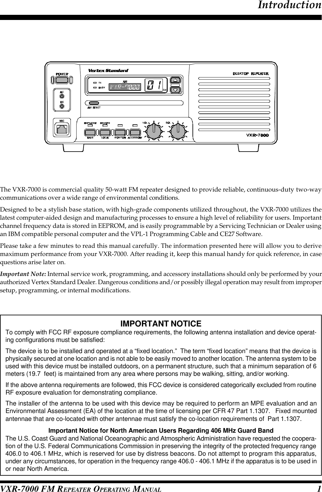
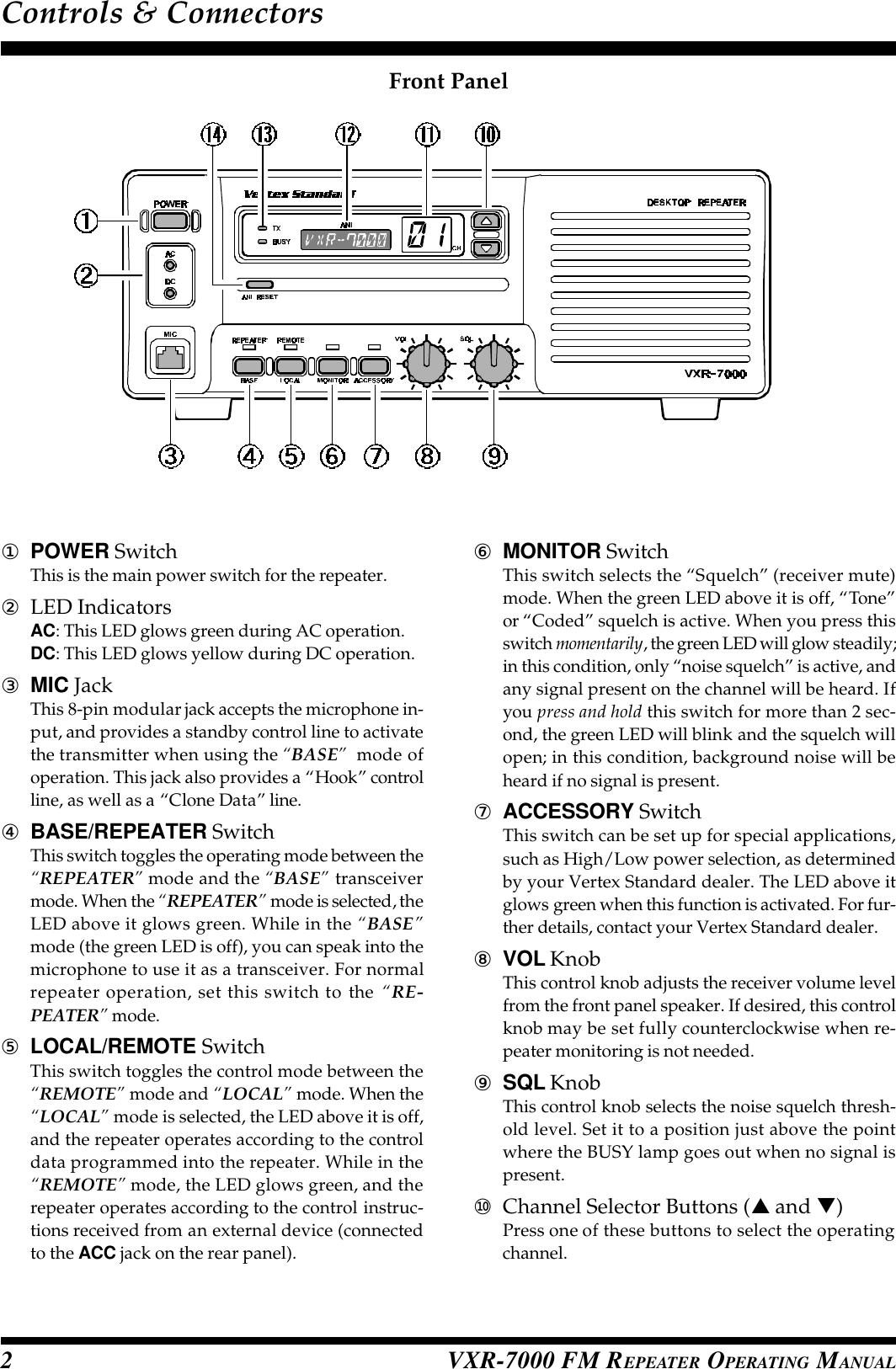
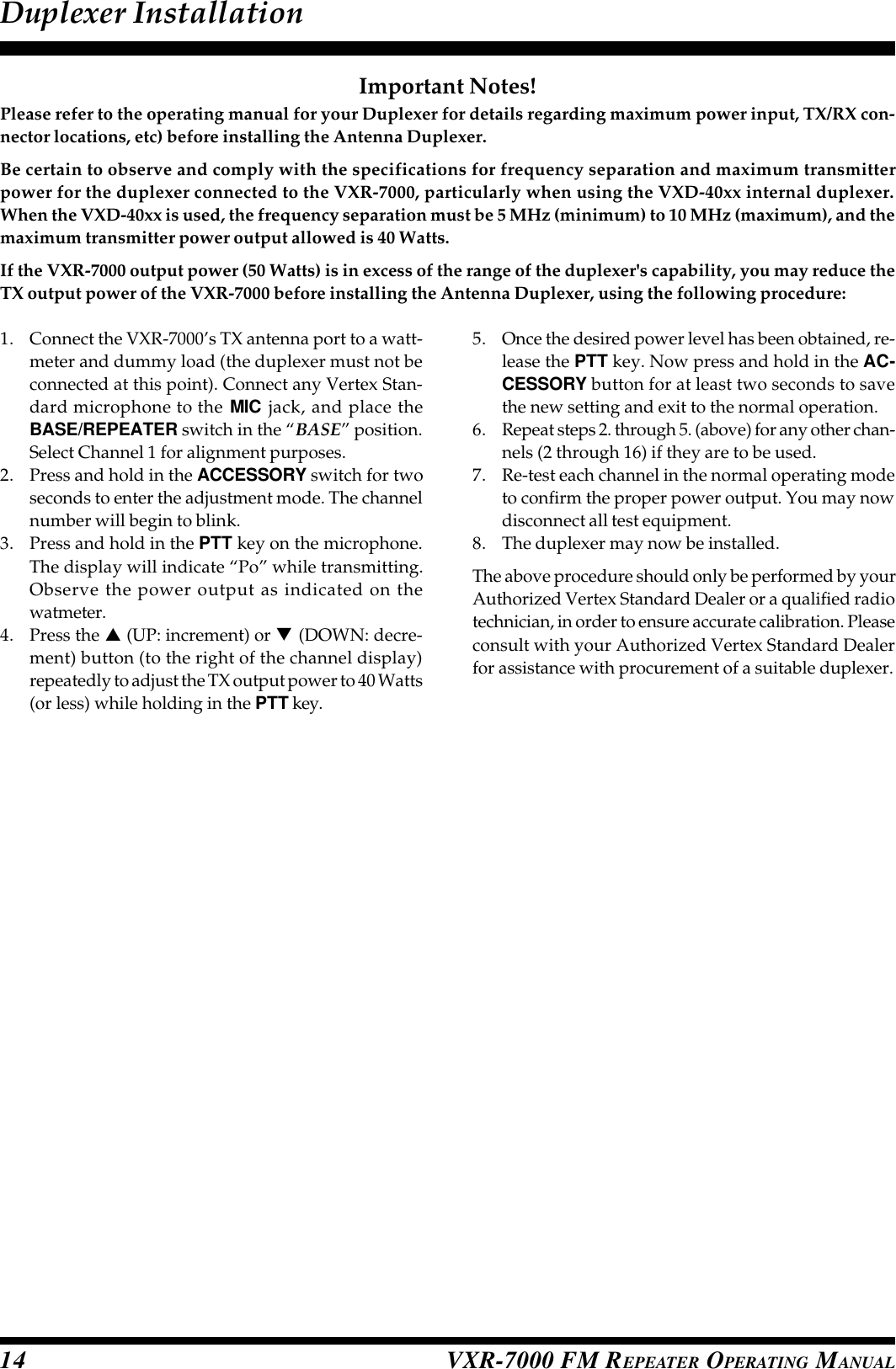
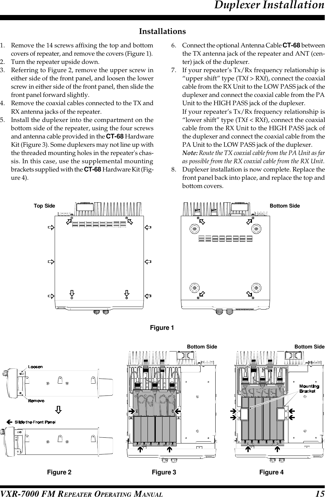
![VXR-7000 FM REPEATER OPERATING MANUAL4The VXR-7000 repeater is provided with a 25-pin DB-25F female connector for interconnections to accesso-ries. Use a DB-25M 25-pin male connector to connectaccessories to the repeater. The pins on the accessoryconnector are explained in detail as follows:Pin 1: GNDChassis ground for all logic levels and power sup-ply return.Pin 2: +13.8 V [Power Supply]This pin provides 13.8 Volts, 1.0 A, regulated DCfrom the repeater supply. Use a 1 A fuse in the exter-nal device’s DC line to prevent damage to the re-peater.Pin 3: TX AF IN [Analog Transmitter Input](Voice Band: 300 ~ 3,000 Hz)Input impedance is approx. 600 Ω. This audio is in-jected before the splatter filter stage, so excess sig-nal input levels are clipped.Use shielded cable to connect to this pin, and con-nect the shield to GND.Pin 4: TONE IN [Transmitter Input](Sub-audible Band: 6 ~ 250 Hz)The input is high impedance (approx. 22 kΩ). In-jecting too high a voltage here causes over-devia-tion of CTCSS or DCS, degrading performance. Useshielded cable to connect to this pin, connecting theshield to GND.Pin 5: N.C. (No connection.)Pin 6: DISC OUT [Analog Output](Wide-Band: 0 ~ 3,000 Hz)Received signals with standard deviation produceapprox. 1 Vp-p audio at this pin. The output imped-ance is approx. 600 Ω, and is extracted before thede-emphasis and squelch circuitry. Use shieldedcable to connect to this pin, and connect the shieldto GND.Pin 7: GNDChassis ground for all logic levels and power sup-ply return.Pin 8: RSSI [Analog Output]A DC voltage proportional to the strength of the sig-nal currently being received (Receiver SignalStrength Indicator) is provided on this pin. This lowimpedance output is generated by the receiver IFsub-system and buffered by an internal op-amp.Typical voltages are graphed as follows:ACC Connector PortPin 9: COAX. SW [Logic Output (Active Low)]This output is intended for controlling an externalcoaxial switching relay. It is an open collector out-put which can sink approx. 10 mA when active. Thissignal only switches if the repeater has been pro-grammed for “SIMPLEX” mode. If programmedfor “DUPLEX,” the signal remains open (high im-pedance) at all time.Pin 10: N.C. (No connection.)Pin 11: NSQ DETThis is an open-collector, active-low output capableof sinking about 10 mA. It indicates that the receiversquelch is open. If the squelch control is properlyset, this indicates a carrier on the receiver channel.Pin 12: EXT PTTThis input is internally pulled up to 5 VDC. Whenpulled low by an external device, it keys the repeatertransmitter while the repeater is operating in the“BASE” mode. Avoid voltage in excess of 5 V onthis pin, or internal damage to the microprocessoron the repeater CNTL Unit may result.ACC JackDB-25 Pin Numbering](https://usermanual.wiki/Yaesu-Musen/VXR-7000U-2/User-Guide-127378-Page-6.png)
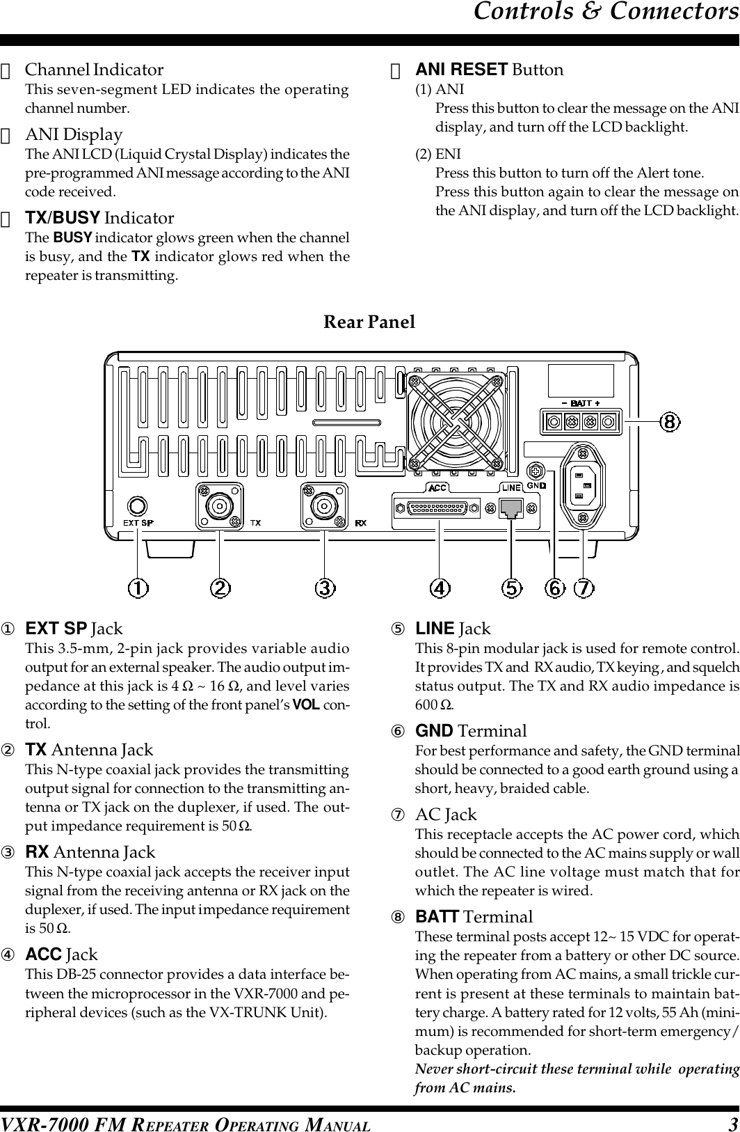
![VXR-7000 FM REPEATER OPERATING MANUAL 5Pin 13: GNDChassis ground for all logic levels and power sup-ply return.Pin 14: GNDChassis ground for all logic levels and power sup-ply return.Pin 15: N.C. (No connection.)Pin 16, 17, 18, & 19: REMOTE CH DATA[Logic Inputs D3, D2, D1, and D0] (Active Low)These inputs are internally pulled up to 5-V DC.When pulled low by an external device, they selectone of the 16 pre-programmed repeater operatingchannels. The logic truth table below shows the com-binations for selecting all 16 channels.In the truth table, “1” represents no connection, and“0” represents a ground connection on the pin.The channel selection logic is not inhibited while thetransmitter is keyed: the repeater will change fre-quency when instructed, even while transmitting.Avoid voltage in excess of 5 V on these pins or inter-nal damage to the microprocessor on the repeaterCNTL Unit may result.ACC Connector PortPin 20: GNDChassis ground for all logic levels and power sup-ply return.Pin 21: A-OUTPUT [Logic Output] (Active Low)This open collector logic output is pulled low whenthe front panel’s ACCESSORY key is turned on. Itcan sink approx. 10 mA when active.Pin 22: RXD LOW[Digital Output for DATA Communications](300 ~ 3,000 Hz)This pin is an output for low speed receiving datasignals, with the data being extracted after the de-emphasis and low pass filter stages.Pin 23: RXD HI[Digital Output for DATA Communications]This pin is an output for high speed receiving datasignals, with the data being extracted immediatelyafter the discriminator prior to any de-emphasis).Pin 24: TXD LOW[Digital Input for DATA Communications](300 ~ 3,000 Hz)This pin is intended to be used as a low speed digi-tal data signal input to the repeater. This digital datasignal is injected before transmitter pre-emphasisand limiting stage, so excess signal input levels areclipped.Pin 25: TXD HI[Digital Input for the DATA Communications]This pin is intended to be used as a high speed digi-tal data signal input to the repeater. This digital datasignal is injected after transmitter splatter filter stage.Channel12345678910111213141516Pin 17(D2)1111000011110000Pin 18(D1)1100110011001100Pin 19(D0)1010101010101010Pin 16(D3)1111111100000000](https://usermanual.wiki/Yaesu-Musen/VXR-7000U-2/User-Guide-127378-Page-7.png)
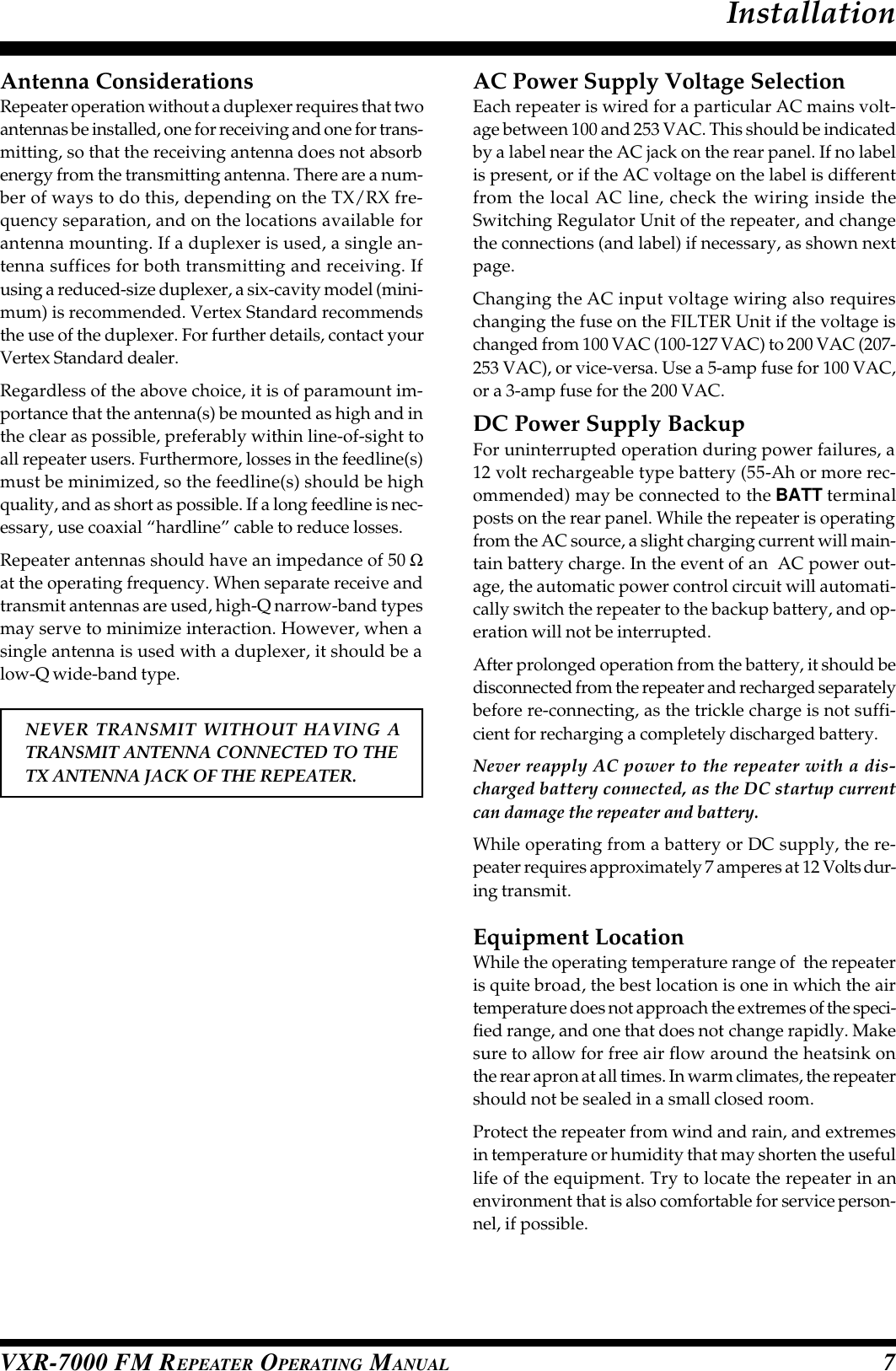
![VXR-7000 FM REPEATER OPERATING MANUAL6The VXR-7000 is provided with an 8-pin modular jackfor line interfacing applications. A Western Electric®modular-type RJ45 plug should be used to connect tothis jack. The LINE jack pin-out is shown below.Note that there are both 4-line and 8-line types of modu-lar plugs. If a 4-line modular plug is used, only the LINEOUT and LINE IN connections will be made. An 8-lineplug is required to access all lines. In accordance withstandard telecommunications interface, the line connec-tions on the LINE interface jack are impedance balanced,and are described as follows.Pins 1 & 2: [RX SQ(+), RX SQ(–)]An opto-isolator is provided to facilitate E (EAR)signaling. The opto-isolator comes on when a signalexceeding the receiver squelch appears on the re-ceiver channel (with correct CTCSS tone or DCScode, if enabled). The RX SQ(–) pin is the emitter,and RX SQ(+) is the collector.Pins 3 & 4: [LINE IN (Tx Line Audio)]Analog signals between 300 and 3000 Hz suppliedto this pair are fed to the transmitter when the re-peater is set to the BASE mode (the REPEATER LEDis turned off) and keyed either by the TX KEY inputsignal (see below), or by the EXT PTT signal on pin12 of the rear panel’s ACC jack. Standard deviationis obtained with a line level of –10 dBm.Pins 5 & 6: [LINE OUT (Rx Line Audio)]Receiver audio is available from this pair, subject tointernal CTCSS or DCS decode if the received sig-nal strength is above the squelch threshold.As shipped from the factory, a 1-kHz receiver signalwith standard deviation gives –10 dBm on the line,but this can be varied by VR4002 and S4001 (on therepeater’s CNTL Unit).Pins 7 & 8 [TX KEY(+), TX KEY(–)]An opto-isolator is provided to facilitate M (MIC)signaling. That is, a voltage presented to these pinsturns on the opto-isolator and keys the transmitter.The TX KEY(+) pin is the anode of the opto-isolator,and RX SQ(–) is the cathode of the opto-isolator.LINE Interface PortLINE JackModular Jack Pin Numbering](https://usermanual.wiki/Yaesu-Musen/VXR-7000U-2/User-Guide-127378-Page-8.png)
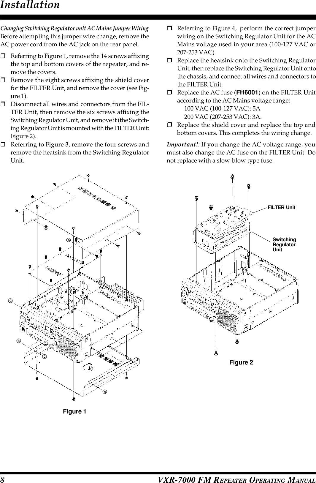

![VXR-7000 FM REPEATER OPERATING MANUAL10With the CE27 Programming Software, you can quicklyand easily program the Vertex Standard VXR-7000repeater’s channels and configuration from your per-sonal computer. Channel data programming format isidentical for VHF and UHF repeaters. In the event of anaccidental memory failure, repeater memory and con-figuration data may be re-loaded in a matter of min-utes.The CE27 Programming Software diskette contains thefollowing files:•CE27.EXE•CE27.HLPBefore connecting the VXR-7000 for programming, turnoff both the computer and the VXR-7000. Now connectthe VPL-1 Connection Cable to the computer’s serial portand the VXR-7000.Then it will be safe to restart the computer; turning offthe equipment during interconnection avoids the poten-tial for damage to the electronics caused by voltagespikes.Insert the distribution diskette into your 3½” drive (af-ter booting DOS), and make a copy of the diskette; usethe distribution diskette for archive purposes, and usethe disk copy for programming.CE27 Programming Software InstructionPlace the CE27 (copy) diskette into your 3½” drive (usu-ally “Drive A”), and log onto this drive by typing “A:[ENTER]”, then load the contents of the CE27 diskette intoa directory named CE27, using the COPY command (e.g.“COPY A:*.* C:\CE27”).Now type “CE27 [ENTER]” to start the program. The in-troductory screen will appear, and you may press anykey to enter the main screen.Choose the “Help” contents option (F1) from theprogram’s Menu for assistance with channel program-ming or setting of parameters.Important Note!rDo not run the CE27 programming software di-rectly from the original distribution diskette.Copy the programming software to yourcomputer's hard disk, then run the softwarefrom the hard disk only. Keep the original dis-tribution diskette in a safe place in case youneed to make another copy of it at a later date.r Before creating the programming data for yourVXR-7000 via the CE27 programming software,upload the current factory hardware environ-ment data from the VXR-7000, using the [F5](ReadRom) command. Use this data profile tocreate the programming data for this repeater.VXR-7000 Programming SetupCE27 Main Screen (Left)](https://usermanual.wiki/Yaesu-Musen/VXR-7000U-2/User-Guide-127378-Page-12.png)
![VXR-7000 FM REPEATER OPERATING MANUAL 11Channel Data ItemsCh: Channel NumberThis 2-digit number (01 - 16) is used to identify the chan-nel. Channel numbers occur in sequence, and their or-der can not be changed.Rx Freq.: Edit Receive (or simplex) FrequencyUse the [0] - [9] keys to enter the desired channel fre-quency directly, and press the [ENTER] key.CTCSS Decoders: Toggle CTCSS Decoder ON/OFF, setsCTCSS FrequencyPress the [SPACE] bar totoggle the CTCSS Decoder“on” or “off,” or press the[ENTER] key to display the“TONE SELECT” window,from which you may selecta CTCSS frequency using the [ARROW] key; press [EN-TER] again to accept the selected tone, or press [ESC] keyto cancel.DCS Decoders: Toggle DCS Decoder ON/OFF, sets DCSCode #Press the [SPACE] bar to toggle the DCS Decoder ON orOFF, or press the [ENTER] key to display the “CODE SE-LECT” window, from which you may select a DCS codeusing the [AR-ROW] key; press[ENTER] againto accept theselected code,or press the[ESC] key tocancel.W/N: Wide/Narrow Channel SpacingThis function selects the channel spacing environmentin which the VXR-7000 operates.W (Wide) = 25 kHz Channel Spacing, ±5 kHz De-viation.N (Narrow) = 12.5 kHz Channel Spacing, ±2.5 kHzDeviation.Press the [SPACE] bar to select the desired channel spac-ing environment.Clk Sft: Enable/disable the CPU Clock ShiftThis function is only used to move a spurious response“birdie” should it fall on a current frequency.Press the [SPACE] bar to toggle “yes” or “no.”NSQ Mode: Noise Squelch ModeThis command selects the manner of setting of theSquelch threshold level.User = The squelch threshold level is fixed via the“NSQ Lv” parameter (NSQ Lv: 0 [min.] ~255 [max.]).Prpgm = The squelch threshold level determined viathe dealer programming.Press the [SPACE] bar to select the desired NSQ Mode.NSQ Lv: Noise Squelch threshould levelUse the [0] - [9] keys to enter the desired Squelch thresh-old level directly, and press the [ENTER] key. Availablevalues are 0 (min.) ~ 255 (max.).Court Blip: Courtesy BlipWhen this parameter is set to “on,” this function causesthe VXR-7000 to send out a “blip” on the portable/mo-bile radio is frequency each time the portable radio isunkeyed. This provides audible confirmation to the userthat the VXR-7000 was able to receive the transmissionfrom the portable.Press the [SPACE] bar to toggle “on” or “off.”CE27 Programming Software InstructionCE27 Main Screen (Scrolled Right)](https://usermanual.wiki/Yaesu-Musen/VXR-7000U-2/User-Guide-127378-Page-13.png)
![VXR-7000 FM REPEATER OPERATING MANUAL12Rev Bst: Reverse Burst.When this parameter is set to “on,” the CTCSS tonesignal’s phase is inverted just before the repeater turnsto receive. This allows the portable/mobile station’sCTCSS Decoder to begin switching off, thus reducingthe transition time required.Press the [SPACE] bar to toggle “on” or “off.”DCS Typ: DCS FormatThis command is effective only when DCS is chosen forsquelch control.A = “Normal” DCSB = “Inverted” (complement) DCSPress the [SPACE] bar to select the desired DCS Type.DDec Type: DCS Decoder TypeThis command selects the manner in which DCS is to bedecoded.Fixed = Decodes only the type selected in above pa-rameter (DCS Typ: Normal or Inverted).Auto = Both types (Normal and Inverted) will bedecoded.Press the [SPACE] bar to select the desired DCS DecoderMode.Multi Tone: Enable/disable Multi Tone OperationPress the [SPACE] bar to toggle Multi Tone Operationbetween selections “yes” and “no.”Press the [ENTER] keyto display the “MULTITONE SELECT” win-dow, from which youmay select a CTCSStone or DCS code;move the cursol to the appropriate field you using the[ARROW] key, then press the [ENTER] key to open the “ TONESELECT” or “CODE SELECT” window. Now select the de-sired CTCSS tone or DCS code using the [ARROW] key,then press the [ENTER] key again to accept the selectedtone or code, or press the [ESC] key to cancel. You mayset as many as 16 CTCSS tones and/or DCS codes.Note that, if you do not yet program a CTCSS tone orDCS code in the “MULTI TONE SELECT” window (whenthe “MULTI TONE SELECT” window data is not pro-grammed), press the [SPACE] bar to display the “MULTITONE SELECT” window directly.CWID ANI/ENI: Select the Identifier modePress the [SPACE] bar to toggle the selections “CW ID,”“ANI/ENI,” or “Off.” To select this feature to the “CWID” or “ANI/ENI,” the “CW ID” parameter must be en-abled via the dealer programming.CE27 Programming Software InstructionAction Mode: Select the repeater operation modePress the [SPACE] bar to toggle between “Duplex” op-eration or “Simplex” operation.Tx Freq.: Edit Transmit FrequencyUse the [0] - [9] keys to enter the desired channel fre-quency directly, and press the [ENTER] key.CTCSS Encoders: Toggle CTCSS Encoder ON/OFF, setsCTCSS FrequencyPress the [SPACE] bar totoggle the CTCSS Encoder“on” or “off,” or press the[ENTER] key to display the“TONE SELECT” window,from which you may selecta CTCSS frequency using the [ARROW] key; press [EN-TER] again to accept the selected tone, or press the [ESC]key to cancel.DCS Encoders: Toggle DCS Encoder ON/OFF, sets DCSCode #Press the [SPACE] bar to toggle the DCS Encoder “on” or“off,” or press the [ENTER] key to display the “CODE SE-LECT” window, from which you may select a DCS codeusing the [AR-ROW] key; press[ENTER] againto accept theselected code,or press the[ESC] key tocancel.Base TOT: Enable/disable the Time-Out Timer while in the“BASE” station modePress the [SPACE] bar to toggle the TOT feature selects“yes” and “no.”The TOT time is determined via dealer programming.Base Guard: Enable/disable the Base Guard FeatureWhen this parameter is set to “yes,” the transmitter willbe inhibited for a few seconds before the repeater (inthe “BASE” station mode) turns to receive.The inhibit time is determined via dealer programming.LOUT: Select the Lock Out Feature’s modePress the [SPACE] bar to toggle the Lock Out Feature be-tween “BCLO,” “BTLO,” or “off,” then press the [En-ter] key to accept the setting. “BCLO” inhibits transmit-ting while there is carrier present. “BTLO” inhibits trans-mitting while there is carrier present unless there also isa valid tone present.](https://usermanual.wiki/Yaesu-Musen/VXR-7000U-2/User-Guide-127378-Page-14.png)
![VXR-7000 FM REPEATER OPERATING MANUAL 13TX Pwr: Transmitter Power Output SelectionThis parameter selects the desired power output fromthe VXR-7000 on the current channel. The available val-ues are HIGH and LOW.Press the [SPACE] bar to select “Hi” or “Lo.”TOT Mute: Enable/disable the TOT (Time-Out Timer) beepmonitoringWhen this parameter is set to “on,” the alert beep willsound from the front panel speaker before the repeaterturns itself off.RptTOT Use: Enable/disable the Time-Out Timer while op-erating in the repeater modePress the [SPACE] bar to toggle the Repeater TOT selects“yes” or “no.”The TOT time is determined via dealer programming.RptTOT Beep: Enable/disable the TOT beep TransmissionPress the [SPACE] bar to toggle the TOT beep selects “ yes”or “no.”When this parameter is set to “yes,” the alert beep willbe sent out on the air before the repeater turns itself off,while oprtating in the “REPEATER” mode.RPT HT: Enable/disable the Repeater Hang-on TimerPress the [SPACE] bar to toggle the Repeater Hang-onTimer selects “yes” or “no.”When this parameter is set to “yes,” the repeater willremain keyed for a desired seconds after a receivingcarrier is dropped.The Hang-up time is determined via dealer program-ming.RPT GT: Enable/disable the Repeater GuardWhen this parameter is set to “yes,” the transmitter in-hibit few second before the repeater is unkeyed.The inhibit time is determined via dealer programming.CE27 Programming Software Instruction](https://usermanual.wiki/Yaesu-Musen/VXR-7000U-2/User-Guide-127378-Page-15.png)