Yaesu Musen VXR-9000U Low Power UHF Transceiver User Manual users manual 1
Yaesu Musen Co., Ltd. Low Power UHF Transceiver users manual 1
UserManual.wiki
>
Yaesu Musen
>
VXR-9000U User Manual
>
users manual 1
Contents
1.
users manual 1
2.
users manual 2
users manual 1
Navigation menu
Upload a User Manual
Namespaces
Wiki Guide
HTML
PDF
Info
Views
User Manual
Discussion / Help
Navigation
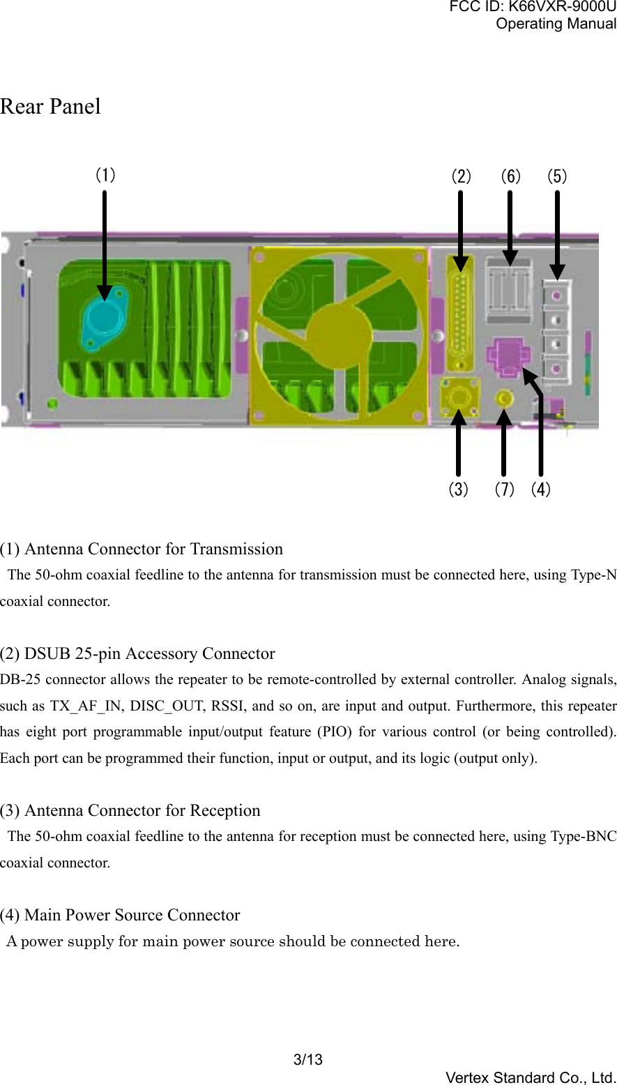
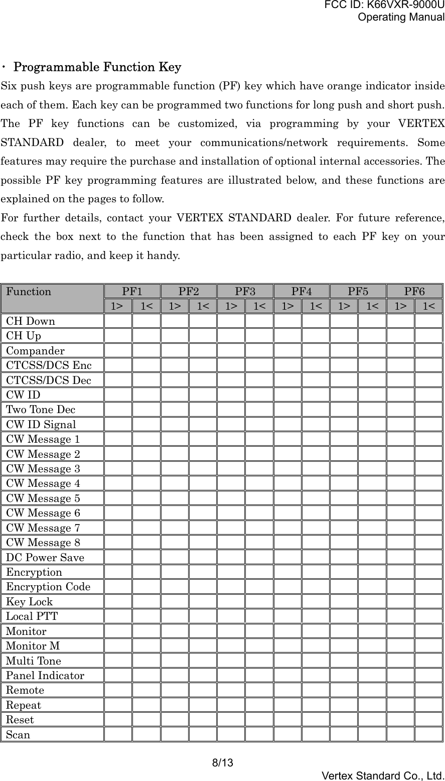
![FCC ID: K66VXR-9000UOperating Manual5/13Vertex Standard Co., Ltd.The VXR-9000 repeater is provided with a 25-pin DB-25F female connector for interconnections toaccessories.Use a DB-25M 25-pin male connector to connect accessories to the repeater. The pins onthe accessoryconnector are explained in detail as follows:Pin 1: GNDChassis ground for all logic levels and power supply return.Pin 2: GNDChassis ground for all logic levels and power supply return.Pin 3: +13.6 V [Power Supply]This pin provides 13.6 Volts, 1.0 A, regulated DCfrom the repeater supply. Use a 1 A fuse in the externaldevice’s DC line to prevent damage to the repeater.Pin 4,6,8,10,12,16,19,25: Programmable I/O_0~7this repeater has eight port programmable input/output feature (PIO) for various control (or beingcontrolled). Each port can be programmed their function, input or output, and its logic (output only).Pin 5: TX AF IN [Analog Transmitter Input](Voice Band: 300 ~ 3,000 Hz)Approximately 0.254 Vrms audio input on this pinwill produce full system deviation at 1 kHz (±5 kHzdeviation with 25 kHz channel spacing, ±2.5 kHzdeviation with 12.5 kHz channel spacing). Input impedanceis 600 .. This audio is injected before thesplatter filter stage, so excess signal input levels areclipped.Use shielded cable to connect to this pin, and connectthe shield to GND.Pin 7: TONE IN [Transmitter Input](Sub-audible Band: 6 ~ 250 Hz)Applying a 0.1 Vrms sub-audible tone produces 10%of full system deviation. The input impedance is 600W, and has a flat response characteristic (repeaterdeviation is constant for a given signal level overthe frequency range of 6 ~ 250 Hz). Injecting too higha voltage here causes over-deviation of CTCSS orDCS, degrading performance. Use shielded cable toconnect to this pin, connecting the shield to GND.](https://usermanual.wiki/Yaesu-Musen/VXR-9000U.users-manual-1/User-Guide-330975-Page-5.png)
Received signals with full system deviation produce1 Vp-p audio at this pin. The output impedance is600 ., and is extracted before the de-emphasis andsquelch circuitry. Use shielded cable to connect tothis pin, and connect the shield to GND.Pin 13: GNDChassis ground for all logic levels and power supply return.Pin 14: GNDChassis ground for all logic levels and power supply return.Pin 15: RSSI [Analog Output]A DC voltage proportional to the strength of the signalcurrently being received (Receiver SignalStrength Indicator) is provided on this pin. This lowimpedance output is generated by the receiver IFsub-system and buffered by an internal op-amp.Typical voltages are graphed as follows:Pin 17: COAX. SW [Logic Output (Active Low)]This output is intended for controlling an externalcoaxial switching relay. It is an open collector outputwhich can sink approx. 10 mA when active. Thissignal only switches if the repeater has been programmedfor “SIMPLEX” mode. If programmedfor “DUPLEX,” the signal remains open (high impedance)at all time.Pin 18: RXD LOW[Digital Output for DATA Communications](300 ~ 3,000 Hz)This pin is an output for low speed receiving datasignals (typically 1200 bps), with the data being extracted](https://usermanual.wiki/Yaesu-Musen/VXR-9000U.users-manual-1/User-Guide-330975-Page-6.png)
This pin is an output for high speed receiving datasignals (typically 9600 bps), with the data being extractedimmediately after the discriminator prior toany de-emphasis).Pin 21: NSQ DETThis is an open-collector, active-low output capableof sinking about 10 mA. It indicates that the receiversquelch is open. If the squelch control is properlyset, this indicates a carrier on the receiver channel.Pin 22: TXD LOW[Digital Input for DATA Communications](300 ~ 3,000 Hz)This pin is intended to be used as a low speed digitaldata signal input to the repeater (typically 1200bps). This digital data signal is injected before transmitterpre-emphasis and limiting stage, so excess signalinput levels are clipped.Pin 23: EXT PTTThis input is internally pulled up to 5 VDC. Whenpulled low by an external device, it keys the repeatertransmitter while the repeater is operating in theBASE mode. Avoid voltage in excess of 5 V on thispin, or internal damage to the microprocessor on therepeater CNTL Unit may result.Pin 24: TXD HIGH[Digital Input for the DATA Communications](0 ~ 5 kHz)This pin is intended to be used as a high speed digitaldata signal input to the repeater (typically 9600bps). This digital data signal is injected after transmittersplatter filter stage.](https://usermanual.wiki/Yaesu-Musen/VXR-9000U.users-manual-1/User-Guide-330975-Page-7.png)