Yamaha 2002 Royal Star Venture Owners Manual
2015-03-13
: Yamaha 2002-Royal-Star-Venture-Owners-Manual yamaha-2002-royal-star-venture-owners-manual-648349 yamaha pdf
Open the PDF directly: View PDF ![]() .
.
Page Count: 145 [warning: Documents this large are best viewed by clicking the View PDF Link!]
XVZ13TF
OWNER’S MANUAL
EAU00002 INTRODUCTION
Congratulations on your purchase of the Yamaha Royal Star™ VENTURE®. This
model is the result of Yamaha’s vast experience in the production of fine sporting,
touring, and pacesetting racing machines. It represents the high degree of crafts-
manship and reliability that have made Yamaha a leader in these fields.
This manual will give you an understanding of the operation, inspection, and basic
maintenance of this motorcycle. If you have any questions concerning the operation
or maintenance of your motorcycle, please consult a Yamaha dealer.
The design and manufacture of this Yamaha motorcycle fully comply with the emis-
sions standards for clean air applicable at the date of manufacture. Yamaha has met
these standards without reducing the performance or economy of operation of the
motorcycle. To maintain these high standards, it is important that you and your
Ya maha dealer pay close attention to the recommended maintenance schedules and
operating instructions contained within this manual.
EAU00003
IMPORTANT MANUAL INFORMATION
Particularly important information is distinguished in this manual by the following notations:
The Safety Alert Symbol means ATTENTION! BECOME ALERT! YOUR SAFETY IS
INVOLVED!
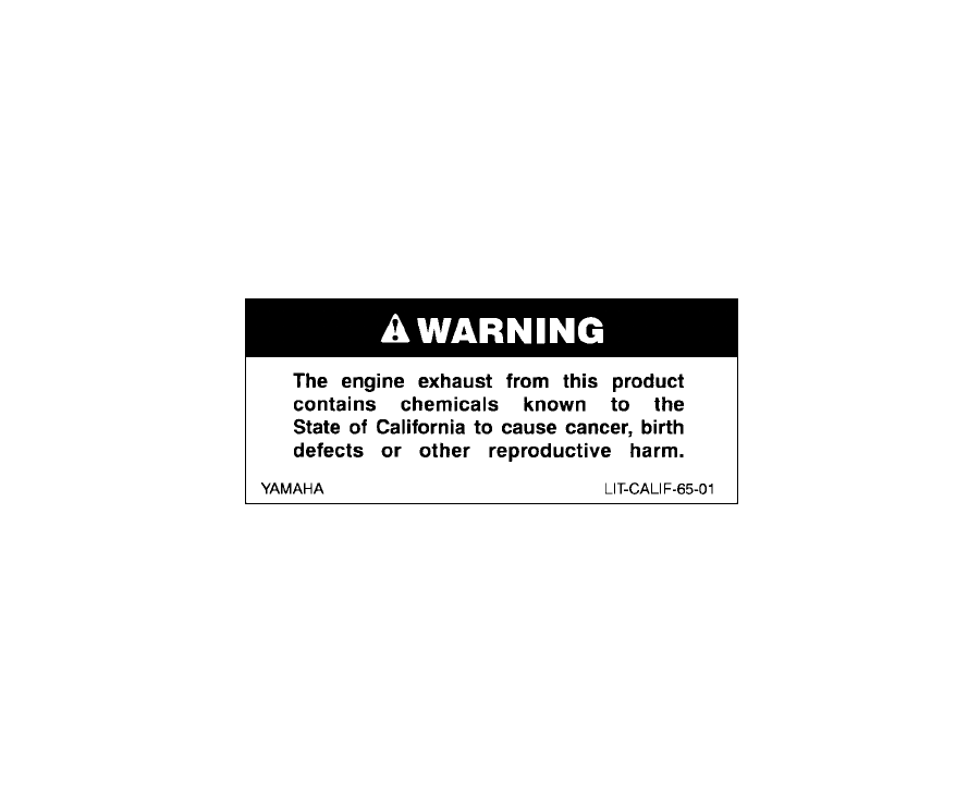
WARNING Failure to follow WARNING instructions could result in severe injury or death to the
motorcycle operator, a bystander or a person inspecting or repairing the motorcycle.
CAUTION: A CAUTION indicates special precautions that must be taken to avoid damage to the
motorcycle.
NOTE: A NOTE provides key information to make procedures easier or clearer.
NOTE:
@
●This manual should be considered a permanent part of this motorcycle and should remain
with it even if the motorcycle is subsequently sold.
●Yamaha continually seeks advancements in product design and quality. Therefore, while
this manual contains the most current product information available at the time of printing,
there may be minor discrepancies between your motorcycle and this manual. If you have
any questions concerning this manual, please consult your Yamaha dealer.
@
IMPORTANT MANUAL INFORMATION
EW000000
WARNING
@
PLEASE READ THIS MANUAL AND THE “YOU AND YOUR MOTORCYCLE: RIDING
TIPS” BOOKLET CAREFULLY AND COMPLETELY BEFORE OPERATING THIS MOTOR-
CYCLE. DO NOT ATTEMPT TO OPERATE THIS MOTORCYCLE UNTIL YOU HAVE AT-
TAINED ADEQUATE KNOWLEDGE OF ITS CONTROLS AND OPERATING FEATURES
AND UNTIL YOU HAVE BEEN TRAINED IN SAFE AND PROPER RIDING TECHNIQUES.
REGULAR INSPECTIONS AND CAREFUL MAINTENANCE, ALONG WITH GOOD RIDING
SKILLS, WILL ENSURE THAT YOU SAFELY ENJOY THE CAPABILITIES AND THE RELI-
ABILITY OF THIS MOTORCYCLE.
@
IMPORTANT MANUAL INFORMATION
AFFIX DEALER
LABEL HERE
EAU04247
XVZ13TFP(C)
OWNER’S MANUAL
© 2001 by Yamaha Motor Corporation, U.S.A.
1st edition, July 2001
All rights reserved.
Any reprinting or unauthorized use
without the written permission of
Yamaha Motor Corporation, U.S.A.
is expressly prohibited.
Printed in Japan.
P/N LIT-11626-15-33
TABLE OF CONTENTS
1SAFETY INFORMATION 1
2DESCRIPTION 2
3INSTRUMENT AND CONTROL FUNCTIONS 3
4AUDIO SYSTEM AND CB RADIO 4
5PRE-OPERATION CHECKS 5
6OPERATION AND IMPORTANT RIDING POINTS 6
7PERIODIC MAINTENANCE AND MINOR REPAIR 7
8CLEANING AND STORAGE 8
9SPECIFICATIONS 9
10 CONSUMER INFORMATION 10
INDEX
SAFETY INFORMATION
1
Safe riding.......................................................................................... 1-1
Protective apparel .............................................................................. 1-3
Modifications ...................................................................................... 1-3
Loading and accessories ................................................................... 1-3
Gasoline and exhaust gas.................................................................. 1-5
Location of important labels .............................................................. 1-7
1
1-1
1-
SAFETY INFORMATION EAU03633
MOTORCYCLES ARE SINGLE TRACK VEHICLES. THEIR SAFE USE AND OPERATION ARE
DEPENDENT UPON THE USE OF PROPER RIDING TECHNIQUES AS WELL AS THE EXPERTISE
OF THE OPERATOR. EVERY OPERATOR SHOULD KNOW THE FOLLOWING REQUIREMENTS
BEFORE RIDING THIS MOTORCYCLE.
HE OR SHE SHOULD:
1. OBTAIN THOROUGH INSTRUCTIONS FROM A COMPETENT SOURCE ON ALL ASPECTS OF
MOTORCYCLE OPERATION.
2. OBSERVE THE WARNINGS AND MAINTENANCE REQUIREMENTS IN THE OWNER’S MANUAL.
3. OBTAIN QUALIFIED TRAINING IN SAFE AND PROPER RIDING TECHNIQUES.
4. OBTAIN PROFESSIONAL TECHNICAL SERVICE AS INDICATED BY THE OWNER’S MANUAL
AND/OR WHEN MADE NECESSARY BY MECHANICAL CONDITIONS.
Safe riding
1. Always make pre-operation checks. Careful checks may help prevent an accident.
2. This motorcycle is designed to carry the operator and a passenger.
3. The failure of motorists to detect and recognize motorcycles in traffic is the predominating cause of
automobile/motorcycle accidents. Many accidents have been caused by an automobile driver who
did not see the motorcycle. Making yourself conspicuous appears to be very effective in reducing the
chance of this type of accident.
Therefore:
a. Wear a brightly colored jacket.
b. Use extra caution when approaching and passing through intersections, since intersections are
the most likely places for motorcycle accidents to occur.
c. Ride where other motorists can see you. Avoid riding in another motorist’s blind spot.

SAFETY INFORMATION
1
1-2
4. Many motorcycle accidents involve inexperienced operators. In fact, many operators who have been
involved in accidents do not even have a current motorcycle license.
a. Make sure that you are qualified and that you only lend your motorcycle to other qualified opera-
tors.
b. Know your skills and limits. Staying within your limits may help you to avoid an accident.
c. We recommend that you practice riding your motorcycle where there is no traffic until you have
become thoroughly familiar with the motorcycle and all of its controls.
5. Many motorcycle accidents have been caused by error of the motorcycle operator. A typical error
made by the operator is veering wide on a turn due to EXCESSIVE SPEED or undercornering (insuf-
ficient lean angle for the speed).
a. Always obey the speed limit and never travel faster than warranted by road and traffic conditions.
b. Always signal before turning or changing lanes. Make sure that other motorists can see you.
6. The posture of the operator and passenger is important for proper control.
a. The operator should keep both hands on the handlebar and both feet on the operator footrests
during operation to maintain control of the motorcycle.
b. The passenger should always hold onto the operator, seat strap, or grab bar, if equipped, with
both hands and keep both feet on the passenger footrests.
c. Never carry a passenger unless he or she can firmly place both feet on the passenger footrests.
7. Never ride under the influence of alcohol or other drugs.
8. This motorcycle is designed for on-road use only, therefore, it is not suitable for off-road use.

SAFETY INFORMATION
1
1-3
Protective apparel
The majority of fatalities from motorcycle accidents are the result of head injuries. The use of a safety
helmet is the single most critical factor in the prevention or reduction of head injuries.
1. Always wear an approved helmet.
2. Wear a face shield or goggles. Wind in your unprotected eyes could contribute to an impairment of vi-
sion which could delay seeing a hazard.
3. The use of a jacket, heavy boots, trousers, gloves, etc., is effective in preventing or reducing abra-
sions or lacerations.
4. Never wear loose-fitting clothes, otherwise they could catch on the control levers, footrests, or wheels
and cause injury or an accident.
5. Never touch the engine or exhaust system during or after operation. They become very hot and can
cause burns. Always wear protective clothing that covers your legs, ankles, and feet.
6. Passengers should also observe the precautions mentioned above.
Modifications
Modifications made to this motorcycle not approved by Yamaha, or the removal of original equipment,
may render the motorcycle unsafe for use and may cause severe personal injury. Modifications may
also make your motorcycle illegal to use.
Loading and accessories
Adding accessories or cargo to your motorcycle can adversely affect stability and handling if the
weight distribution of the motorcycle is changed. To avoid the possibility of an accident, use extreme
caution when adding cargo or accessories to your motorcycle. Use extra care when riding a
motorcycle that has added cargo or accessories. Here are some general guidelines to follow if loading
cargo or adding accessories to your motorcycle:

SAFETY INFORMATION
1
1-4
Loading
The total weight of the operator, passenger, accessories and cargo must not exceed the maximum
load limit of XVZ13TF(C): 419 lb (190 kg). When loading within this weight limit, keep the following in
mind:
1. Cargo and accessory weight should be kept as low and close to the motorcycle as possible. Make
sure to distribute the weight as evenly as possible on both sides of the motorcycle to minimize imbal-
ance or instability.
2. Shifting weights can create a sudden imbalance. Make sure that accessories and cargo are securely
attached to the motorcycle before riding. Check accessory mounts and cargo restraints frequently.
3. Never attach any large or heavy items to the handlebar, front fork, or front fender. These items, in-
cluding such cargo as sleeping bags, duffel bags, or tents, can create unstable handling or slow
steering response.
Accessories
Genuine Yamaha accessories have been specifically designed for use on this motorcycle. Since
Yamaha cannot test all other accessories that may be available, you must personally be responsible
for the proper selection, installation and use of non-Yamaha accessories. Use extreme caution when
selecting and installing any accessories.
Keep the following guidelines in mind, as well as those provided under “Loading” when mounting acces-
sories.
1. Never install accessories or carry cargo that would impair the performance of your motorcycle. Care-
fully inspect the accessory before using it to make sure that it does not in any way reduce ground
clearance or cornering clearance, limit suspension travel, steering travel or control operation, or ob-
scure lights or reflectors.
SAFETY INFORMATION
1
1-5
a. Accessories fitted to the handlebar or the front fork area can create instability due to improper
weight distribution or aerodynamic changes. If accessories are added to the handlebar or front
fork area, they must be as lightweight as possible and should be kept to a minimum.
b. Bulky or large accessories may seriously affect the stability of the motorcycle due to aerodynamic
effects. Wind may attempt to lift the motorcycle, or the motorcycle may become unstable in cross
winds. These accessories may also cause instability when passing or being passed by large ve-
hicles.
c. Certain accessories can displace the operator from his or her normal riding position. This improp-
er position limits the freedom of movement of the operator and may limit control ability, therefore,
such accessories are not recommended.
2. Use caution when adding electrical accessories. If electrical accessories exceed the capacity of the
motorcycle’s electrical system, an electric failure could result, which could cause a dangerous loss of
lights or engine power.
Gasoline and exhaust gas
1. GASOLINE IS HIGHLY FLAMMABLE:
a. Always turn the engine off when refueling.
b. Take care not to spill any gasoline on the engine or exhaust system when refueling.
c. Never refuel while smoking or in the vicinity of an open flame.
2. Never start the engine or let it run for any length of time in a closed area. The exhaust fumes are poi-
sonous and may cause loss of consciousness and death within a short time. Always operate your
motorcycle in an area that has adequate ventilation.
3. Always turn the engine off before leaving the motorcycle unattended and remove the key from the
main switch. When parking the motorcycle, note the following:

SAFETY INFORMATION
1
1-6
a. The engine and exhaust system may be hot, therefore, park the motorcycle in a place where pe-
destrians or children are not likely to touch these hot areas.
b. Do not park the motorcycle on a slope or soft ground, otherwise it may fall over.
c. Do not park the motorcycle near a flammable source (e.g. a kerosene heater, or near an open
flame), otherwise it could catch fire.
4. When transporting the motorcycle in another vehicle, make sure that it is kept upright and that the fuel
cock is turned to “ON” or “RES” (for vacuum type) / “OFF” (for manual type). If it should lean over,
gasoline may leak out of the carburetor or fuel tank.
5. If you should swallow any gasoline, inhale a lot of gasoline vapor, or allow gasoline to get into your
eyes, see your doctor immediately. If any gasoline spills on your skin or clothing, immediately wash
the affected area with soap and water and change your clothes.
SAFETY INFORMATION
1
1-7
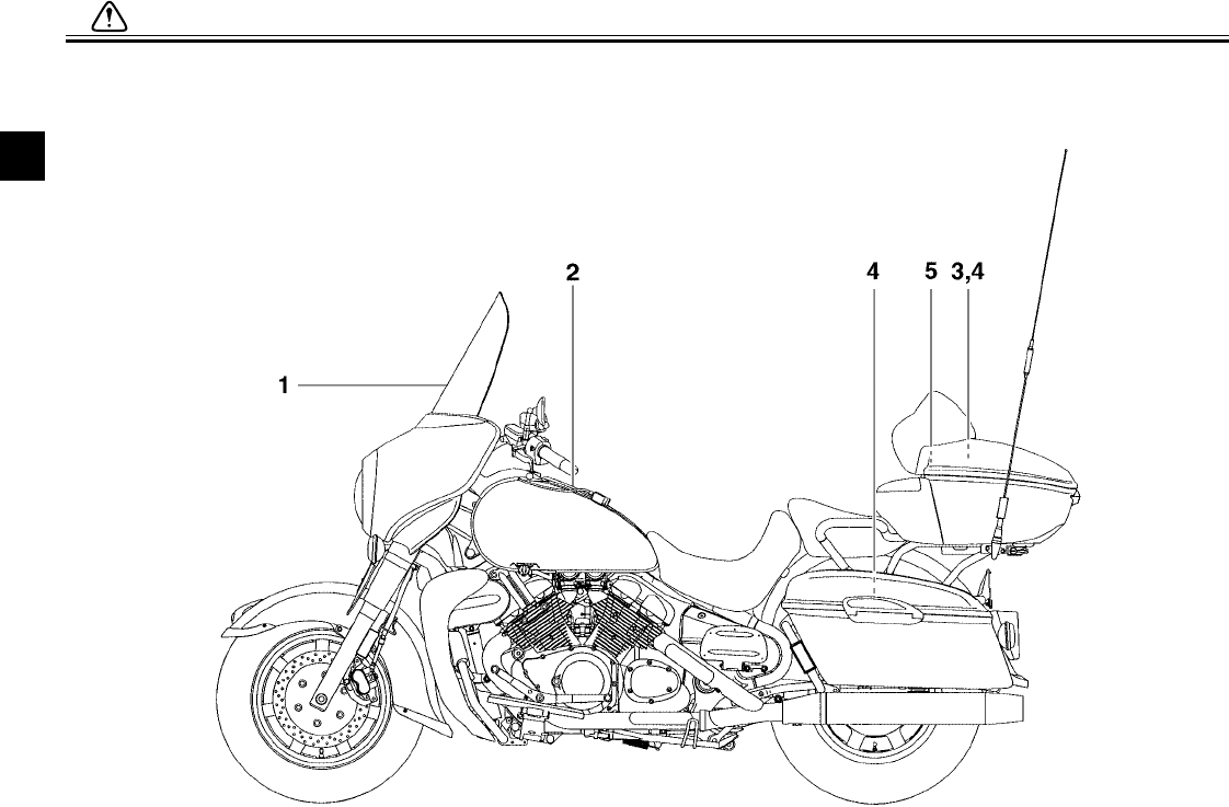
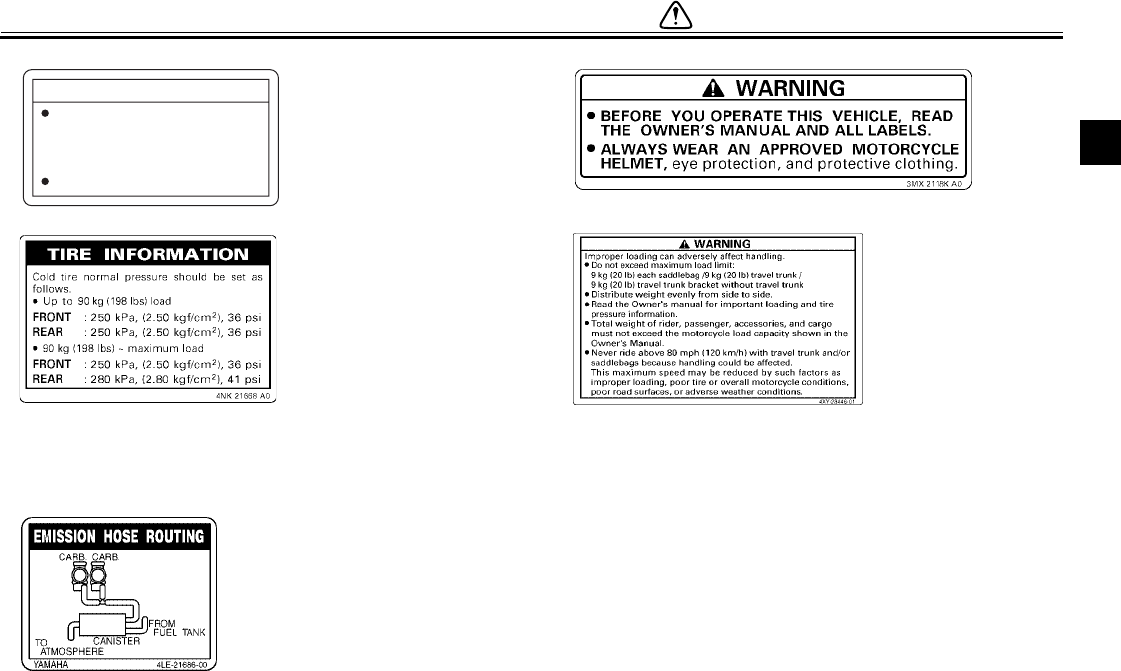
EAU02977
Location of important labels
Please read the following important labels carefully before operating this motorcycle.
SAFETY INFORMATION
1
1-8
12
34
5 CALIFORNIA ONLY
CAUTION
Cleaning with alkaline or
acid cleaner, gasoline or
solvent will damage
windshield.
Use nautral detergent.
5LV-2835Y-00

DESCRIPTION
2
Left view............................................................................................. 2-1
Right view........................................................................................... 2-2
Controls and instruments ................................................................... 2-3
2-1
2
EAU00026
2-
DESCRIPTION
Royal Star™ VENTURE®
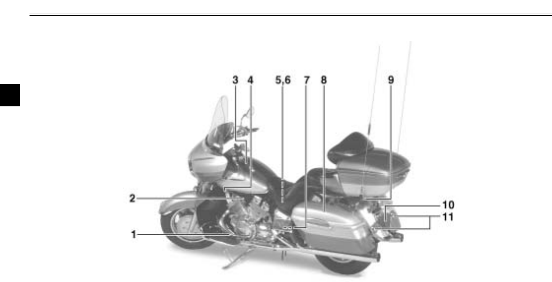
Left view
1. Shift pedal (page 3-9)
2. Starter (choke) knob (page 3-13)
3. Fuel tank cap (page 3-10)
4. Fuel cock (page 3-12)
5. Battery (page 7-34)
6. Coolant reservoir (page 7-16)
7. Fuse box 2 (page 7-36)
8. Side case (page 3-15)
9. Helmet holder (page 3-14)
10. Tail/brake light (page 7-38)
11. Rear turn signal lights (page 7-38)
DESCRIPTION
2-2
2
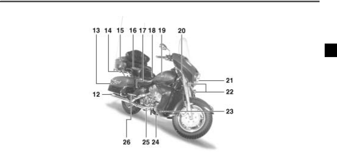
Royal Star™ VENTURE®
Right view
12. Muffler
13. Owner’s tool kit (page 7-2)
14. Helmet holder (page 3-14)
15. Travel trunk (page 3-16)
16. Passenger seat
17. Shock absorber air valve (page 3-18)
18. Rider seat (page 3-13)
19. Fuel tank (page 3-11)
20. Front fork air valve (page 3-17)
21. Headlight (page 7-37)
22. Front turn signal/position lights (page 7-38)
23. Fuse box 1 (page 7-35)
24. Brake pedal (page 3-10)
25. Rider footrest
26. Passenger footrest
DESCRIPTION
2-3
2
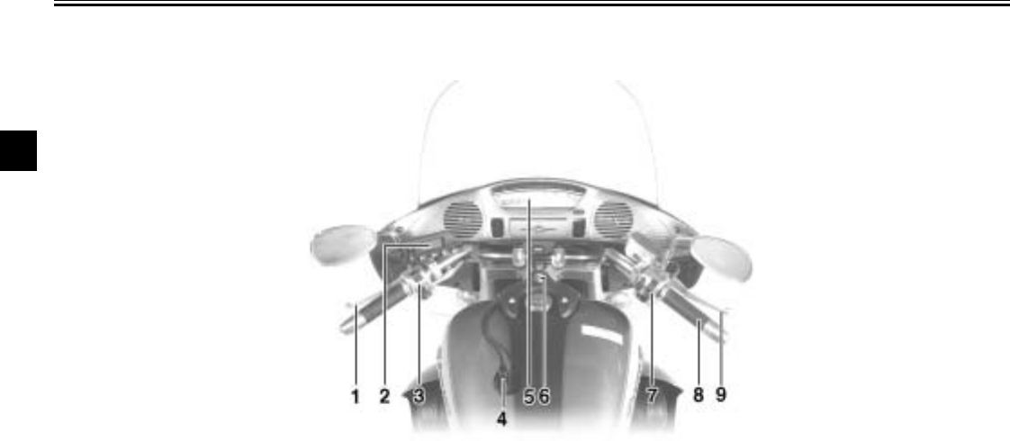
Royal Star™ VENTURE®
Controls and instruments
1. Clutch lever (page 3-9)
2. Audio system/CB radio control unit (page 4-3)
3. Left handlebar switches (page 3-7)
4. Rider headset jack (page 4-2)
5. Speedometer unit (page 3-4)
6. Main switch/steering lock (page 3-1)
7. Right handlebar switches (page 3-8)
8. Throttle grip (page 7-21)
9. Brake lever (page 3-9)

3
INSTRUMENT AND CONTROL FUNCTIONS
Main switch/steering lock .....................................3-1
Indicator and warning lights ................................3-2
Speedometer unit ................................................3-4
Cruise control system ..........................................3-5
Fuel gauge ...........................................................3-7
Handlebar switches .............................................3-7
Clutch lever ..........................................................3-9
Shift pedal ............................................................3-9
Brake lever ...........................................................3-9
Brake pedal ........................................................3-10
Fuel tank cap .....................................................3-10
Fuel ....................................................................3-11
Fuel cock ...........................................................3-12
Starter (choke) knob .......................................... 3-13
Locking the steering with a padlock .................. 3-13
Rider seat .......................................................... 3-13
Helmet holders .................................................. 3-14
Side cases and travel trunk ............................... 3-15
Adjusting the front fork ...................................... 3-17
Adjusting the shock absorber assembly ............ 3-18
Locks for the optional side cases and
travel trunk ...................................................... 3-19
Sidestand .......................................................... 3-19
Ignition circuit cut-off system ............................. 3-20
Auxiliary DC jack and terminals ........................ 3-22
3-1
3
EAU00027
3-
INSTRUMENT AND CONTROL FUNCTIONS
EAU00029
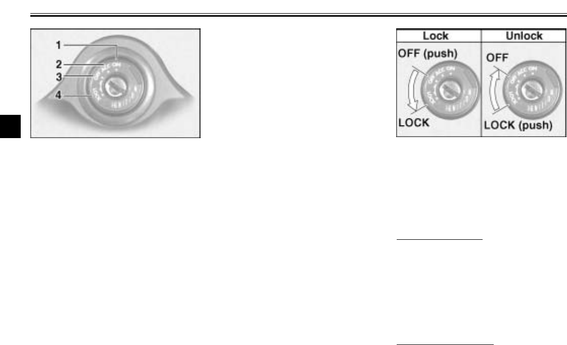
Main switch/steering lock
The main switch/steering lock controls
the ignition and lighting systems, and is
used to lock the steering. The various
positions are described below.
EAU00032
ON
All electrical systems are supplied with
power, and the headlight, meter light-
ing, taillight and position lights come
on, and the engine can be started. The
key cannot be removed.
EAU01842
ACC (Accessory)
The audio system and the auxiliary DC
jack and terminals can be used in this
position. Therefore, do not use the ac-
cessory position for an extended period
of time, otherwise the battery may dis-
charge.
The key cannot be removed.
EAU00038
OFF
All electrical systems are off. The key
can be removed.
EAU00040
LOCK
The steering is locked, and all electrical
systems are off. The key can be re-
moved.
To lock the steering
1. Turn the handlebars all the way to
the left.
2. Push the key in from the “OFF” po-
sition, and then turn it to “LOCK”
while still pushing it.
3. Remove the key.
To unlock the steering
Push the key in, and then turn it to
“OFF” while still pushing it.
1. ON
2. ACC (Accessory)
3. OFF
4. LOCK
INSTRUMENT AND CONTROL FUNCTIONS
3-2
3
EW000016
WARNING
@
Never turn the key to “OFF” or
“LOCK” while the motorcycle is
moving, otherwise the electrical
systems will be switched off, which
may result in loss of control or an
accident. Make sure that the motor-
cycle is stopped before turning the
key to “OFF” or “LOCK”.
@
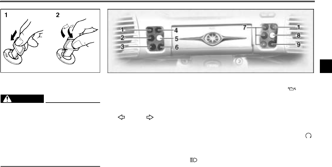
1. Push.
2. Turn. EAU03034
Indicator and warning lights
EAU04121
1. Turn signal indicator lights
“” and “ ”
The corresponding indicator light flash-
es when the turn signal switch is
pushed to the left or right.
EAU00063
2. High beam indicator light “ ”
This indicator light comes on when the
high beam of the headlight is switched
on.
EAU03201
3. Oil level warning light “ ”
This warning light comes on when the
engine oil level is low.
The electrical circuit of the warning light
can be checked according to the fol-
lowing procedure.
1. Set the engine stop switch to “ ”
and turn the key to “ON”.
2. Shift the transmission into the neu-
tral position or pull the clutch lever.
3. Push the start switch. If the warn-
ing light does not come on while
pushing the start switch, have a
Yamaha dealer check the electri-
cal circuit.
INSTRUMENT AND CONTROL FUNCTIONS
3-3
3
NOTE:
@
Even if the oil level is sufficient, the
warning light may flicker when riding on
a slope or during sudden acceleration
or deceleration, but this is not a mal-
function.
@
EAU01774
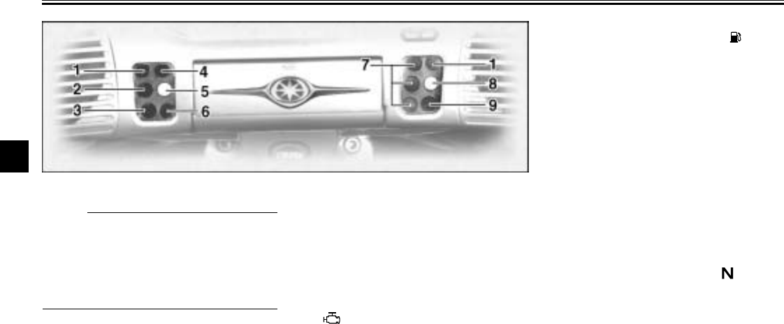
4. Overdrive indicator light “O/D”
This indicator light comes on when the
transmission is in overdrive (5th gear).
EAU04241
5. Engine trouble warning light
“”
This warning light comes on or flashes
when an electrical circuit monitoring
the engine is defective. When this oc-
curs, have a Yamaha dealer check the
self-diagnosis system.
EAU00079
6. Fuel level warning light “ ”
This warning light comes on when the
fuel level drops below approximately
0.9 US gal (0.8 Imp gal, 3.5 L). When
this occurs, turn the fuel cock lever to
the “RES” position and refuel as soon
as possible.
EAU01773
7. Cruise control indicator lights
See page 3-5 for an explanation of
these indicator lights.
EAU00061
8. Neutral indicator light “ ”
This indicator light comes on when the
transmission is in the neutral position.
INSTRUMENT AND CONTROL FUNCTIONS
3-4
3
EAU01707
9. Coolant temperature warning
light “ ”
This warning light comes on when the
engine overheats. When this occurs,
stop the engine immediately and allow
the engine to cool.
The electrical circuit of the warning light
can be checked according to the fol-
lowing procedure.
1. Set the engine stop switch to “ ”
and turn the key to “ON”.
2. Shift the transmission into the neu-
tral position or pull the clutch lever.
3. Push the start switch. If the warn-
ing light does not come on while
pushing the start switch, have a
Yamaha dealer check the electri-
cal circuit.
EC000002
CAUTION:
@
Do not operate the engine if it is
overheated.
@
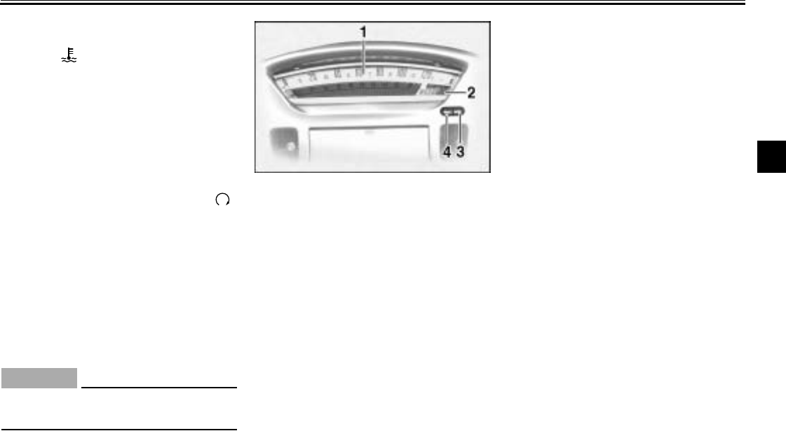
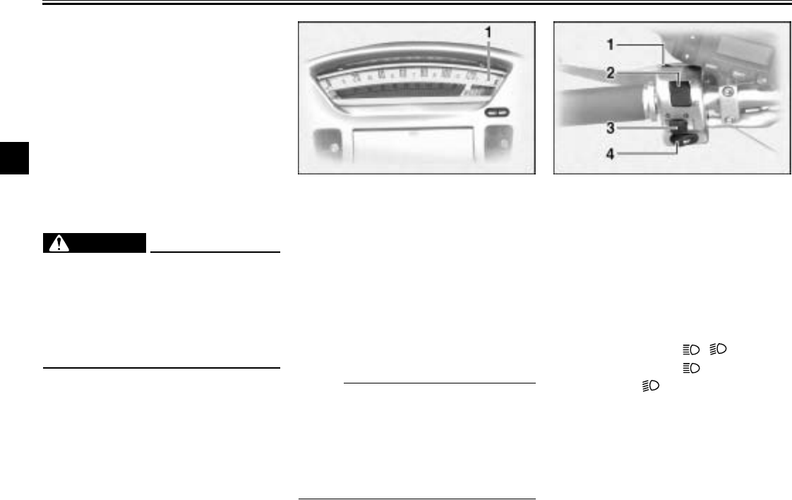
EAU03565
Speedometer unit
The speedometer unit is equipped with
the following:
●a digital speedometer (which
shows riding speed)
●an odometer (which shows the to-
tal distance traveled)
●two tripmeters (which show the
distance traveled since they were
last set to zero)
●a fuel reserve tripmeter (which
shows the distance traveled on the
fuel reserve)
●a clock
Odometer and tripmeter modes
Pushing the “SELECT” button switches
the display between the odometer
mode “ODO” and the tripmeter modes
“TRIP 1” and “TRIP 2” in the following
order:
ODO → TRIP 1 → TRIP 2 → ODO
If the fuel level warning light comes on
(see page 3-3), the odometer display
will automatically change to the fuel re-
serve tripmeter mode “TRIP F” and
start counting the distance traveled
from that point. In that case, pushing
the “SELECT” button switches the dis-
play between the various tripmeter and
odometer modes in the following order:
TRIP F → TRIP 1 → TRIP 2 → ODO →
TRIP F
1. Speedometer
2. Odometer/tripmeter/clock
3. “RESET” button
4. “SELECT” button
INSTRUMENT AND CONTROL FUNCTIONS
3-5
3
To reset a tripmeter, select it by push-
ing the “SELECT” button, and then
push the “RESET” button. If you do not
reset the fuel reserve tripmeter manu-
ally, it will reset itself automatically and
the display will return to “TRIP 1” after
refueling and traveling 5 km (3 mi).
NOTE:
_
After resetting the fuel reserve tripme-
ter, the display will return to “TRIP 1”,
unless a different mode had been pre-
viously selected; in that case, the dis-
play automatically returns to the prior
mode.
_
Clock mode
To change the display to the clock
mode, push both the “SELECT” and
“RESET” buttons.
To change the display back to the
odometer modes, push the “SELECT”
button.
To set the clock:
1. Push both the “SELECT” and “RE-
SET” buttons for at least two sec-
onds.
2. When the hour digits start flashing,
push the “RESET” button to set
the hours.
3. Push the “SELECT” button, and
the minute digits will start flashing.
4. Push the “RESET” button to set
the minutes.
5. Push the “SELECT” button to start
the clock.
NOTE:
_
After setting the clock, be sure to push
the “SELECT” button before turning the
key to “OFF”, otherwise the clock will
not be set.
_
EAU04037
Cruise control system
This motorcycle is equipped with a
cruise control system designed to
maintain a set traveling speed.
Activating and setting the cruise
control system
The cruise control system can only be
activated when riding in 4th or 5th gear
at speeds between 30 mi/h (50 km/h)
and 80 mi/h (130 km/h).
1. “CRUISE” switch
INSTRUMENT AND CONTROL FUNCTIONS
3-6
3
To activate and set the cruise control
system:
1. Push the “CRUISE” switch to the
left. The “ON” indicator light will
come on.
2. Press the “SET/DEC” (set/decel-
erate) side of the cruise control
switch to activate the cruise con-
trol system. The “SET” indicator
light comes on.
3. Set the desired traveling speed as
follows. Press the “RES/ACC” (re-
sume/accelerate) side of the
cruise control switch to increase
the set speed or the “SET/DEC”
side to decrease the speed.
NOTE:
_
Pressing the cruise control switch once
will change the speed in increments of
1 mi/h (1.6 km/h). Holding the cruise
control switch down will increase or de-
crease the speed continuously until the
switch is released.
_
The traveling speed can be set to a
maximum of 80 mi/h (130 km/h) and a
minimum of 30 mi/h (50 km/h).
When the cruise control system is acti-
vated and the throttle grip is turned to
increase the speed by up to 5 mi/h
(8 km/h), the cruise control system will
return to the set speed after the throttle
grip is released. However, if the speed
is increased by more than 5 mi/h
(8 km/h), the cruise control system will
be deactivated until the traveling speed
is within 5 mi/h (8 km/h) of the set
speed.
Deactivating the cruise control
system
Applying the front or rear brake or dis-
engaging the clutch will automatically
deactivate the cruise control system.
Push the “CANCEL” switch to manually
deactivate cruise control.
NOTE:
_
●When the cruise control system is
deactivated, the “RES” (resume)
indicator light will come on.
●Traveling speed decreases as
soon as the cruise control system
is deactivated; unless the throttle
grip is turned.
_
1. Cruise control switch
2. “CANCEL” switch
1. “SET” indicator light
2. “RES” indicator light
3. “ON” indicator light
INSTRUMENT AND CONTROL FUNCTIONS
3-7
3
Push the “RES/ACC” side of the cruise
control switch to reactivate the system.
The traveling speed will return to the
previously set speed. The “RES” indi-
cator light will flash during this time and
then go off. Once the cruise control
system is reactivated, the “SET” indica-
tor light will come on.
Push the “CRUISE” switch to the right
to turn the cruise control system off
completely.
EWA00019
WARNING
_
If the cruise control system is defec-
tive, the “SET” and “RES” indicator
lights will flash simultaneously. If
this occurs, turn the cruise control
system off and have a Yamaha deal-
er check it.
_
EAU01779
Fuel gauge
The fuel gauge indicates the amount of
fuel in the fuel tank. The display seg-
ments of the fuel gauge disappear to-
wards “E” (Empty) as the fuel level
decreases. When only one segment is
left near “E”, refuel as soon as possi-
ble.
NOTE:
@
This fuel gauge is equipped with a self-
diagnosis system. If the electrical cir-
cuit is defective, first the display seg-
ments and then either “E” or “F” will
flash. If this occurs, have a Yamaha
dealer check the electrical circuit.
@
EAU00118
Handlebar switches
EAU01780
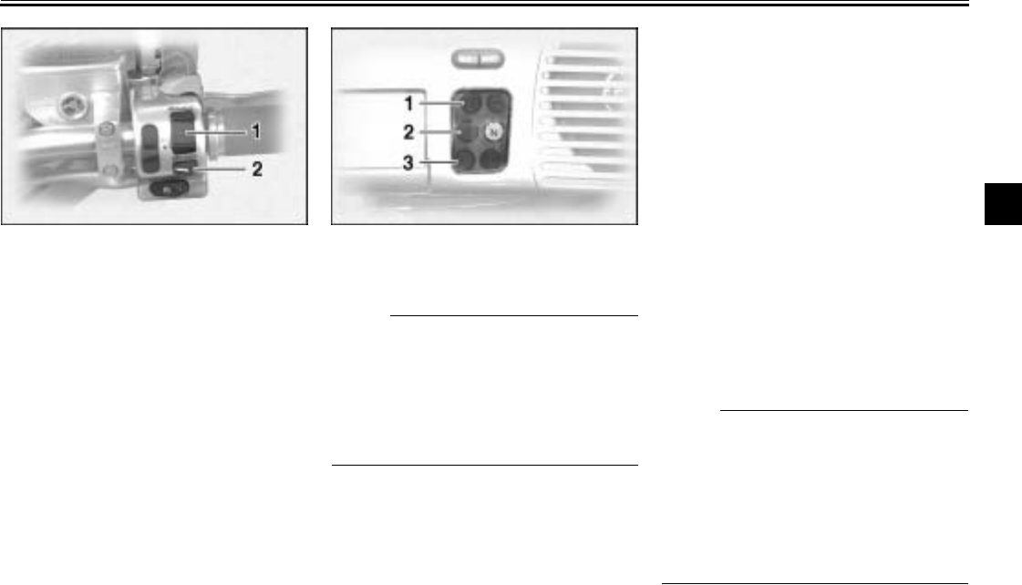
1. “TALK” switch
See page 4-23 for an explanation of the
CB radio.
EAU03888
2. Dimmer switch “ / ”
Set this switch to “ ” for the high
beam and to “ ” for the low beam.
1. Fuel gauge
INSTRUMENT AND CONTROL FUNCTIONS
3-8
3
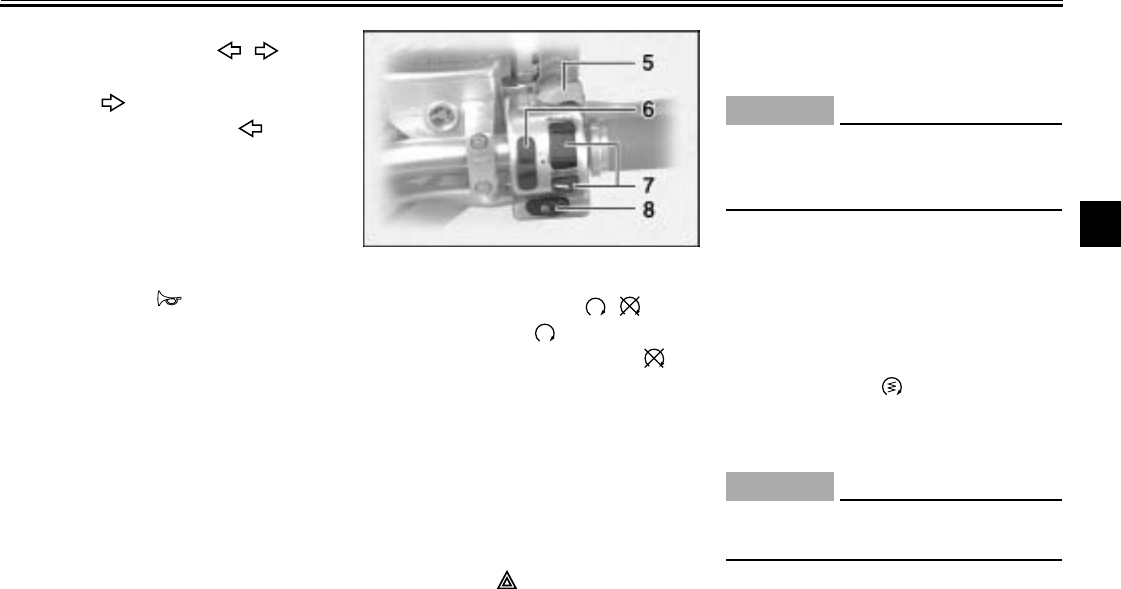
EAU03889
3. Turn signal switch “ / ”
To signal a right-hand turn, push this
switch to “ ”. To signal a left-hand
turn, push this switch to “ ”. When
released, the switch returns to the cen-
ter position. To cancel the turn signal
lights, push the switch in after it has re-
turned to the center position.
EAU00129
4. Horn switch “ ”
Press this switch to sound the horn.
EAU03890
5. Engine stop switch “ / ”
Set this switch to “ ” before starting
the engine. Set this switch to “ ” to
stop the engine in case of an emergen-
cy, such as when the motorcycle over-
turns or when the throttle cable is
stuck.
EAU00147
6. Hazard switch
With the key in the “ON” position, turn
this switch to “ ” to turn on the haz-
ard light (simultaneous flashing of all
turn signal lights).
The hazard light is used in case of an
emergency or to warn other drivers
when your motorcycle is stopped
where it might be a traffic hazard.
EC000006
CAUTION:
@
Do not use the hazard light for an ex-
tended length of time, otherwise the
battery may discharge.
@
EAU01859
7. Cruise control switches
See page 3-5 for an explanation of the
cruise control system.
EAU00143
8. Start switch “ ”
Push this switch to crank the engine
with the starter.
EC000005
CAUTION:
@
See page 6-2 for starting instruc-
tions prior to starting the engine.
@
INSTRUMENT AND CONTROL FUNCTIONS
3-9
3
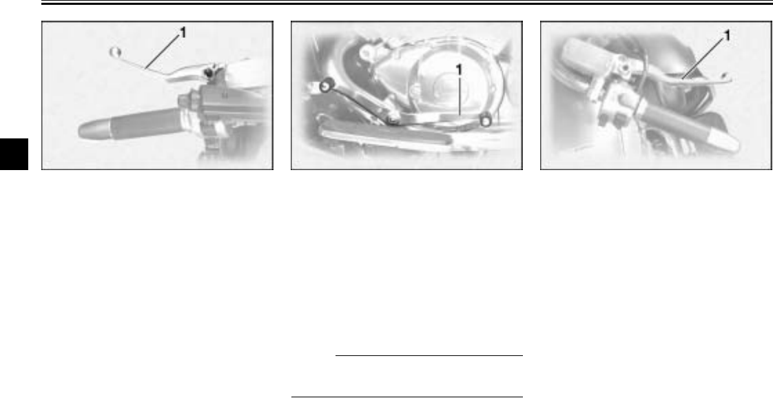
EAU00152
Clutch lever
The clutch lever is located at the left
handlebar grip. To disengage the
clutch, pull the lever toward the handle-
bar grip. To engage the clutch, release
the lever. The lever should be pulled
rapidly and released slowly for smooth
clutch operation.
The clutch lever is equipped with a
clutch switch, which is part of the ignition
circuit cut-off system. (See page 3-20
for an explanation of the ignition circuit
cut-off system.)
EAU01215
Shift pedal
The shift pedal is located on the left
side of the engine and is used in com-
bination with the clutch lever when
shifting the gears of the 5-speed con-
stant-mesh transmission equipped on
this motorcycle.
NOTE:
@
Use your toes or heel to shift up and
your toes to shift down.
@
EAU00158
Brake lever
The brake lever is located at the right
handlebar grip. To apply the front
brake, pull the lever toward the handle-
bar grip.
1. Clutch lever 1. Shift pedal 1. Brake lever
INSTRUMENT AND CONTROL FUNCTIONS
3-10
3
EAU00162
Brake pedal
The brake pedal is on the right side of
the motorcycle. To apply the rear
brake, press down on the brake pedal.
EAU02917
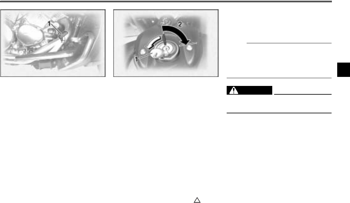
Fuel tank cap
To remove the fuel tank cap
Slide the lock cover open, insert the
key into the lock, and then turn it
1/4 turn clockwise. The lock will be re-
leased and the fuel tank cap can be re-
moved.
To install the fuel tank cap
1. Insert the fuel tank cap into the
tank opening with the key inserted
in the lock and with the “ ” mark
facing forward.
2. Turn the key counterclockwise to
the original position, remove it,
and then close the lock cover.
N
O
TE:
@
The fuel tank cap cannot be installed
unless the key is in the lock. In addition,
the key cannot be removed if the cap is
not properly installed and locked.
@
EW000024
WARNING
@
Make sure that the fuel tank cap is
properly installed before riding.
@
1. Brake pedal 1. Fuel tank cap lock cover
2. Unlock.
INSTRUMENT AND CONTROL FUNCTIONS
3-11
3
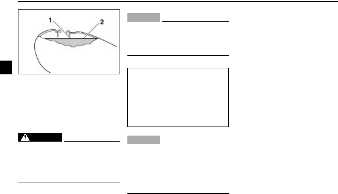
EAU03753
Fuel
Make sure that there is sufficient fuel in
the tank. Fill the fuel tank to the bottom
of the filler tube as shown.
EW000130
WARNING
_
●Do not overfill the fuel tank, oth-
erwise it may overflow when the
fuel warms up and expands.
●Avoid spilling fuel on the hot
engine.
_
EAU00185
CAUTION:
@
Immediately wipe off spilled fuel
with a clean, dry, soft cloth, since
fuel may deteriorate painted surfac-
es or plastic parts.
@
EAU04265
ECA00104
CAUTION:
_
Use only unleaded gasoline. The
use of leaded gasoline will cause se-
vere damage to internal engine
parts, such as the valves and piston
rings, as well as to the exhaust sys-
tem.
_
Your Yamaha engine has been de-
signed to use regular unleaded gaso-
line with a pump octane number
[(R+M)/2] of 86 or higher, or a research
octane number of 91 or higher. If
knocking (or pinging) occurs, use a
gasoline of a different brand or premi-
um unleaded fuel. Use of unleaded fuel
will extend spark plug life and reduce
maintenance costs.
Gasohol
There are two types of gasohol: gaso-
hol containing ethanol and that contain-
ing methanol. Gasohol containing
ethanol can be used if the ethanol con-
tent does not exceed 10%. Gasohol
containing methanol is not recom-
mended by Yamaha because it can
cause damage to the fuel system or ve-
hicle performance problems.
1. Fuel tank filler tube
2. Fuel level
Recommended fuel:
UNLEADED GASOLINE ONLY
Fuel tank capacity:
Total amount:
5.9 US gal (5.0 Imp gal, 22.5 L)
Reserve amount:
0.9US gal (0.8 Imp gal, 3.5 L)
INSTRUMENT AND CONTROL FUNCTIONS
3-12
3
EAU02969
Fuel cock
The fuel cock supplies fuel from the
tank to the carburetors while also filter-
ing it.
The fuel cock lever positions are ex-
plained as follows and shown in the il-
lustrations.
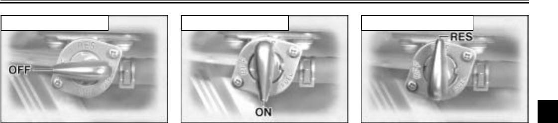
OFF
With the fuel cock lever in this position,
fuel will not flow. Always turn the fuel
cock lever to this position when the en-
gine is not running.
ON
With the fuel cock lever in this position,
fuel flows to the carburetors. Turn the
fuel cock lever to this position when
starting the engine and riding.
RES
This indicates reserve. With the fuel
cock lever in this position, the fuel re-
serve is made available. Turn the fuel
cock lever to this position if you run out
of fuel while riding. When this occurs,
refuel as soon as possible and be sure
to turn the fuel cock lever back to “ON”!
OFF: closed position ON: normal position RES: reserve position
INSTRUMENT AND CONTROL FUNCTIONS
3-13
3
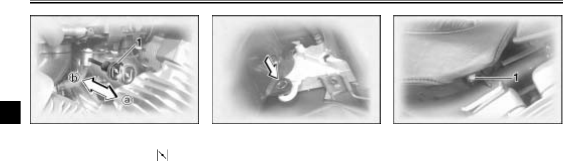
EAU04038
Starter (choke) knob “ ”
Starting a cold engine requires a richer
air-fuel mixture, which is supplied by
the starter (choke).
Move the knob in direction a to turn on
the starter (choke).
Move the knob in direction b to turn off
the starter (choke).
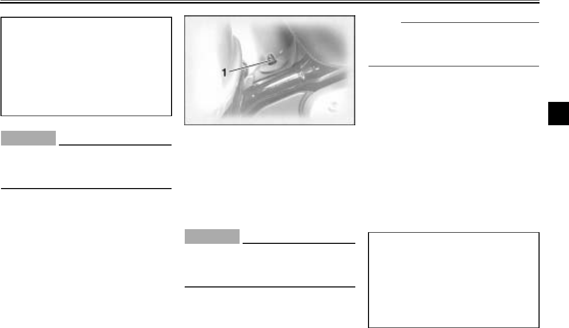
EAU03372
Locking the steering with a
padlock
In addition to the main switch/steering
lock, there are brackets on the right
side of the steering head pipe for lock-
ing the steering with a padlock. To do
so, turn the handlebar until the holes in
the two brackets are aligned, and then
lock the steering with a suitable pad-
lock.
EAU01781
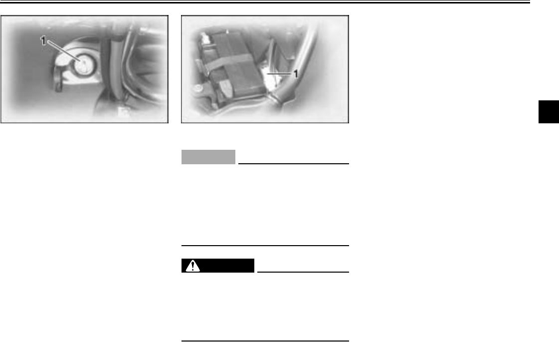
Rider seat
To remove the rider seat
Remove the nuts, and then pull the rid-
er seat up.
1. Starter (choke) knob 1. Nut (× 2)
INSTRUMENT AND CONTROL FUNCTIONS
3-14
3
To install the rider seat
Insert the projection on the rear of the
rider seat into the seat holder as
shown, place the seat in the original
position, and then tighten the nuts.
NOTE:
@
Make sure that the rider seat is proper-
ly secured before riding.
@
EAU01782
Helmet holders
To open a helmet holder
Insert the key into the helmet holder
lock, and then turn it as shown.
To close a helmet holder
Place the helmet holder in the original
position, and then remove the key.
EWA00015
WARNING
@
Never ride with a helmet attached to
a helmet holder, since the helmet
may hit objects, causing loss of
control and possibly an accident.
@
1. Projection
2. Seat holder
1. Helmet holder (right)
2. Unlock.
1. Helmet holder (left)
2. Unlock.
INSTRUMENT AND CONTROL FUNCTIONS
3-15
3
EAU01866
Side cases and travel trunk
EWA00021
WARNING
@
Improper loading or overloading
can cause loss of control and possi-
bly an accident or personal injury.
See pages 1-8 and 7-21 for impor-
tant loading and tire pressure infor-
mation.
●Always securely close the side
cases and travel trunk before
riding.
●Distribute weight evenly on
each side of the motorcycle.
●Do not exceed the load limit of
20 lb (9 kg) for each side case
and the travel trunk.
●Do not exceed the maximum
load of 419 lb (190 kg) for the ve-
hicle.
●Do not exceed 80 mph
(120 km/h) when riding with the
travel trunk, side cases or both
installed, otherwise handling
could be affected. Improper
loading, poor tire or overall mo-
torcycle conditions, poor road
surfaces or adverse weather
conditions may make it neces-
sary to further reduce the riding
speed.
@
Side cases
To open a side case
1. Insert the key into the lock, turn it
counterclockwise, and then push it
in.
2. Fold the side case lid up.
To close a side case
1. Fold the side case lid down.
2. Turn the key clockwise, and then
remove it.
NOTE:
Push both sides of the lid down so that
both latches snap into place.
@
1. Side case lock
2. Unlock.
1. Storage compartment
2. Storage pouch
INSTRUMENT AND CONTROL FUNCTIONS
3-16
3
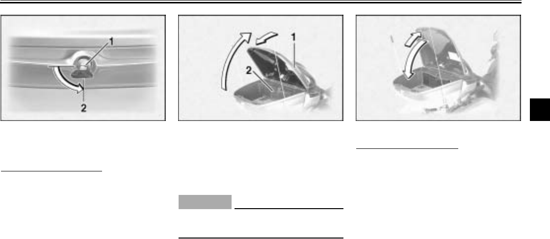
Travel trunk
To open the travel trunk
1. Insert the key into the lock, turn it
counterclockwise, and then push it
in.
2. Fold the travel trunk lid up, and
then release it so that it will rest in
place as shown.
ECA00029
CAUTION:
@
Do not apply excessive pressure on
the travel trunk lid when it is open.
@
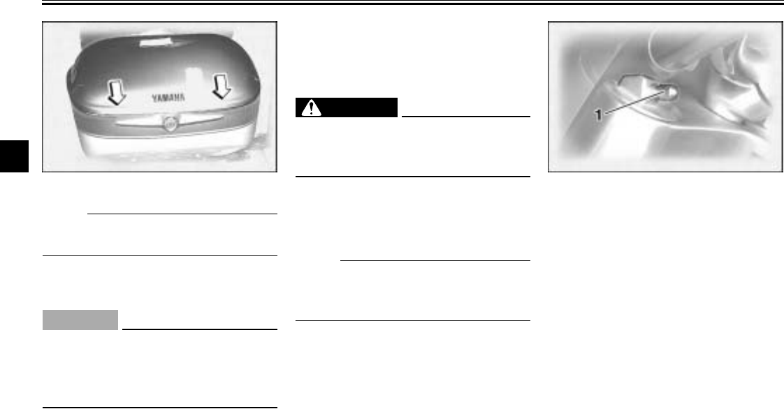
To close the travel trunk
1. Fold the travel trunk lid up com-
pletely, and then fold it down.
1. Travel trunk lock
2. Unlock.
1. Lid resting in opened position
2. Storage pouch
INSTRUMENT AND CONTROL FUNCTIONS
3-17
3
NOTE:
Push both sides of the lid down so that
both latches snap into place.
@
2. Turn the key clockwise, and then
remove it.
ECA00030
CAUTION:
@
To avoid locking the key in, never
lock either side case or the travel
trunk and remove the key from the
lock before closing the lid.
@
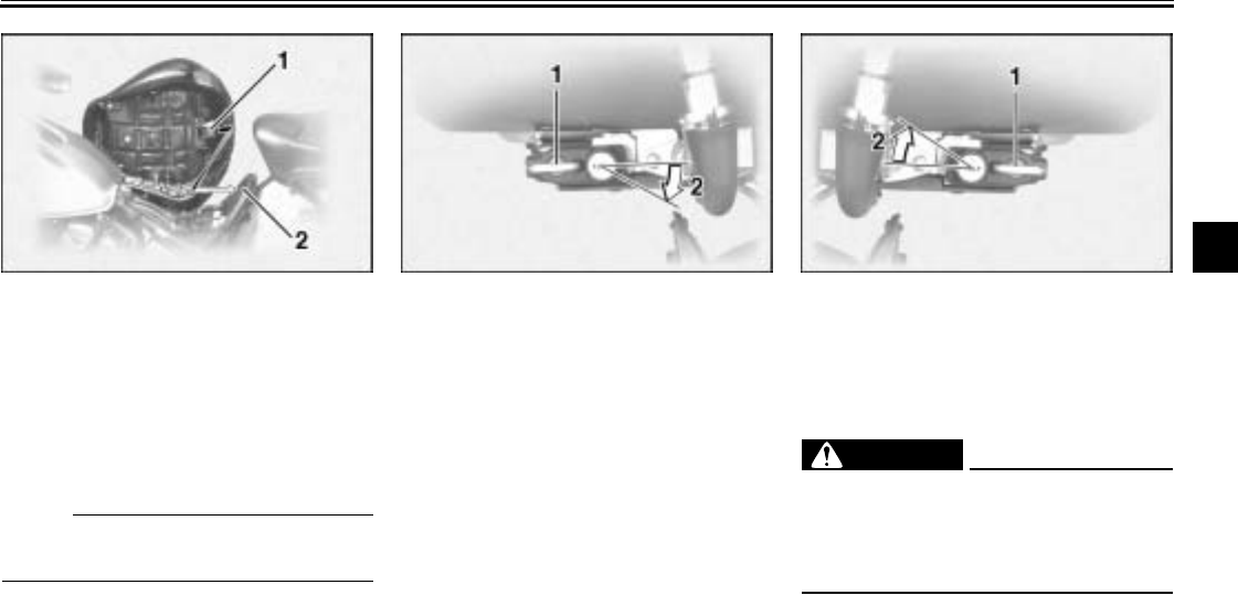
EAU03719*
Adjusting the front fork
This front fork is equipped with air
valves for adjusting the spring rate.
EW000035
WARNING
_
Always adjust both fork legs equal-
ly, otherwise poor handling and loss
of stability may result.
_
Adjust the spring rate as follows.
1. Place the motorcycle on the side-
stand.
NOTE:
_
When checking and adjusting the air
pressure, there should be no weight on
the motorcycle.
_
2. Remove the air valve cap from
each fork leg.
3. Check the air pressure in each
fork leg with the air pressure
gauge included in the owner’s tool
kit.
4. To increase the spring rate and
thereby harden the suspension,
increase the air pressure with an
air pump. To decrease the spring
rate and thereby soften the sus-
pension, decrease the air pres-
sure by pushing each valve stem
down.
1. Front fork air valve cap
INSTRUMENT AND CONTROL FUNCTIONS
3-18
3
EC000012
CAUTION:
_
Never exceed the maximum air pres-
sure, otherwise the front fork oil
seals may become damaged.
_
5. Securely install the air valve caps.
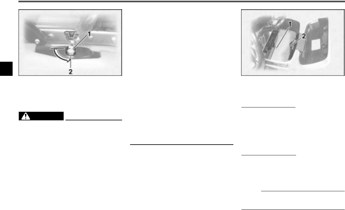
EAU03721*
Adjusting the shock absorber
assembly
This shock absorber assembly is
equipped with an air valve for adjusting
the spring rate.
EC000015
CAUTION:
_
Never attempt to turn an adjusting
mechanism beyond the maximum
or minimum settings.
_
Adjust the spring rate as follows.
1. Place the motorcycle on the side-
stand.
NOTE:
_
When checking and adjusting the air
pressure, there should be no weight on
the motorcycle.
_
2. Remove the air valve cap.
3. Check the air pressure with the air
pressure gauge included in the
owner’s tool kit.
4. To increase the spring rate and
thereby harden the suspension,
increase the air pressure with an
air pump. To decrease the spring
rate and thereby soften the sus-
pension, decrease the air pres-
sure by pushing the valve stem
down.
Spring rate:
Minimum (soft)/standard:
Air pressure =
0 psi (0 kgf/cm2, 0 kPa)
Maximum (hard):
Air pressure =
7.1 psi (0.5 kgf/cm2, 50 kPa)
1. Shock absorber air valve cap
Spring rate:
Minimum (soft)/standard:
Air pressure =
0 psi (0 kgf/cm2, 0 kPa)
Maximum (hard):
Air pressure =
57 psi (4.0 kgf/cm2, 400kPa)
INSTRUMENT AND CONTROL FUNCTIONS
3-19
3
ECA00050
CAUTION:
_
Never exceed the maximum air pres-
sure, otherwise the oil seal may be-
come damaged.
_
5. Securely install the air valve cap.
EAU04043
Locks for the optional side
cases and travel trunk
There are three locks in a plastic bag
located beside the owner’s tool kit.
When used to replace the locks of the
optional side cases and travel trunk,
which can be obtained at a Yamaha
dealer, these locks can be operated
with the ignition key. Keep these locks
in a safe place to prevent losing them.
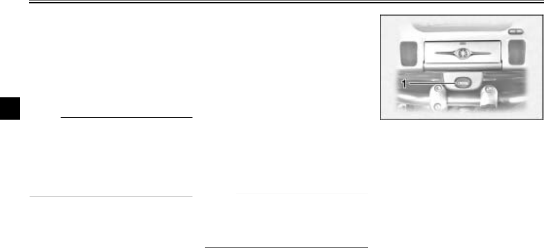
EAU00330
Sidestand
The sidestand is located on the left side
of the frame. Raise the sidestand or
lower it with your foot while holding the
motorcycle upright.
NOTE:
@
The built-in sidestand switch is part of
the ignition circuit cut-off system, which
cuts the ignition in certain situations.
(See further down for an explanation of
the ignition circuit cut-off system.)
@
INSTRUMENT AND CONTROL FUNCTIONS
3-20
3
EW000044
WARNING
@
The motorcycle must not be ridden
with the sidestand down, or if the
sidestand cannot be properly
moved up (or does not stay up), oth-
erwise the sidestand could contact
the ground and distract the opera-
tor, resulting in a possible loss of
control. Yamaha’s ignition circuit
cut-off system has been designed to
assist the operator in fulfilling the
responsibility of raising the side-
stand before starting off. Therefore,
check this system regularly as de-
scribed below and have a Yamaha
dealer repair it if it does not function
properly.
@
EAU03720
Ignition circuit cut-off system
The ignition circuit cut-off system (com-
prising the sidestand switch, clutch
switch and neutral switch) has the fol-
lowing functions.
●It prevents starting when the trans-
mission is in gear and the side-
stand is up, but the clutch lever is
not pulled.
●It prevents starting when the trans-
mission is in gear and the clutch
lever is pulled, but the sidestand is
still down.
●It cuts the running engine when
the transmission is in gear and the
sidestand is moved down.
Periodically check the operation of the
ignition circuit cut-off system according
to the following procedure.
EW000045
WARNING
_
If a malfunction is noted, have a
Yamaha dealer check the system
before riding.
_
INSTRUMENT AND CONTROL FUNCTIONS
3-21
3
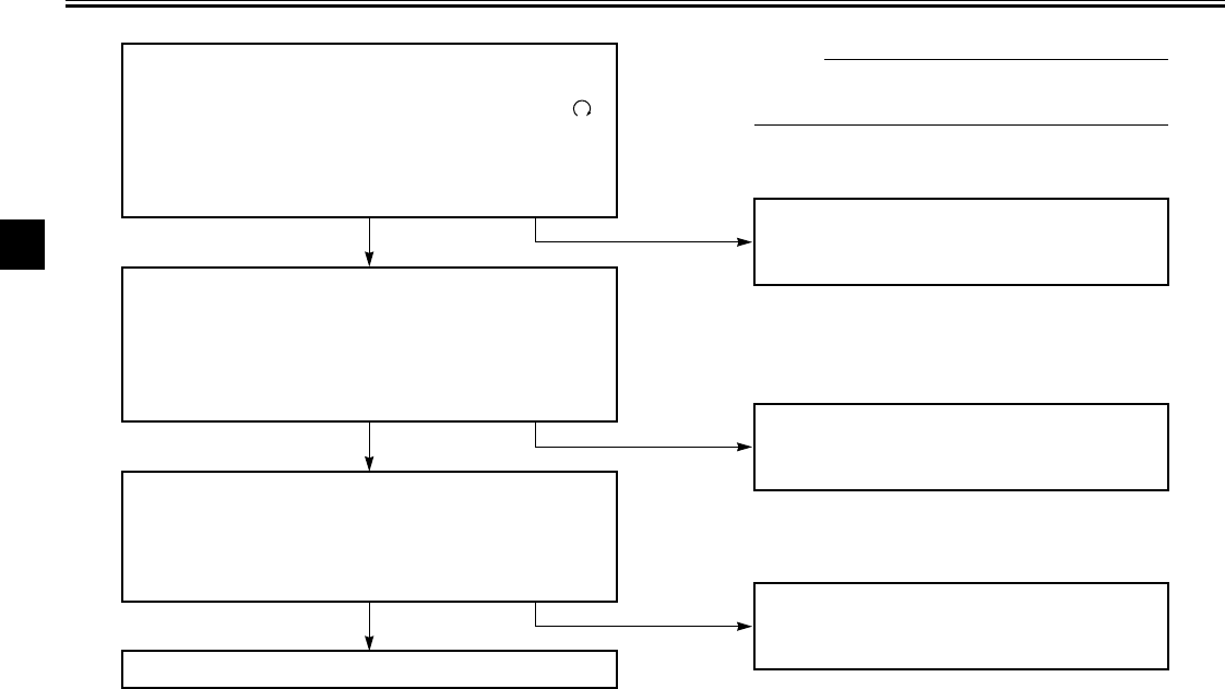
CD-01E
With the engine turned off:
1. Move the sidestand down.
2. Make sure that the engine stop switch is set to “ ”
3. Turn the key to “ON”.
4. Shift the transmission into the neutral position.
5. Push the start switch.
Does the engine start? The neutral switch may be defective.
The motorcycle should not be ridden until
checked by a Yamaha dealer.
With the engine still running:
6. Move the sidestand up.
7. Keep the clutch lever pulled.
8. Shift the transmission into gear.
9. Move the sidestand down.
Does the engine stall?
After the engine has stalled:
10. Move the sidestand up.
11. Keep the clutch lever pulled.
12. Push the start switch.
Does the engine start?
The sidestand switch may be defective.
The motorcycle should not be ridden until
checked by a Yamaha dealer.
The clutch switch may be defective.
The motorcycle should not be ridden until
checked by a Yamaha dealer.
NO
NOTE:
This check is most reliable if performed with
a warmed-up engine.
YES
YES NO
The system is OK. The motorcycle can be ridden.
YES NO
INSTRUMENT AND CONTROL FUNCTIONS
3-22
3
EAU01788
Auxiliary DC jack and
terminals
12-V accessories connected to the
auxiliary DC jack at the front and auxil-
iary DC terminals under the rider seat
can be used when the key is in the
“ACC” or “ON” position.
ECA00044
CAUTION:
@
The accessories connected to the
auxiliary DC jack and terminals
should not be used with the engine
turned off, and their combined load
must never exceed 5 A or 60 W, oth-
erwise the battery may discharge.
@
EWA00017
WARNING
@
To prevent electrical shock or short-
circuiting, make sure that the caps
are installed when the auxiliary DC
jack and terminals are not being
used.
@
1. Auxiliary DC jack 1. Auxiliary DC terminal

AUDIO SYSTEM AND CB RADIO
4
Location of parts ............................................................................... 4-1
Headsets (optional) ........................................................................... 4-2
Control unit ........................................................................................ 4-3
Making basic settings ........................................................................ 4-5
Making mode settings ....................................................................... 4-6
Cassette deck operation .................................................................. 4-10
Radio operation ............................................................................... 4-13
Optional CD changer operation ....................................................... 4-17
CB radio operation .......................................................................... 4-18
Auxiliary audio source operation ..................................................... 4-24
4-1
4
EAU03567
4-
AUDIO SYSTEM AND CB RADIO
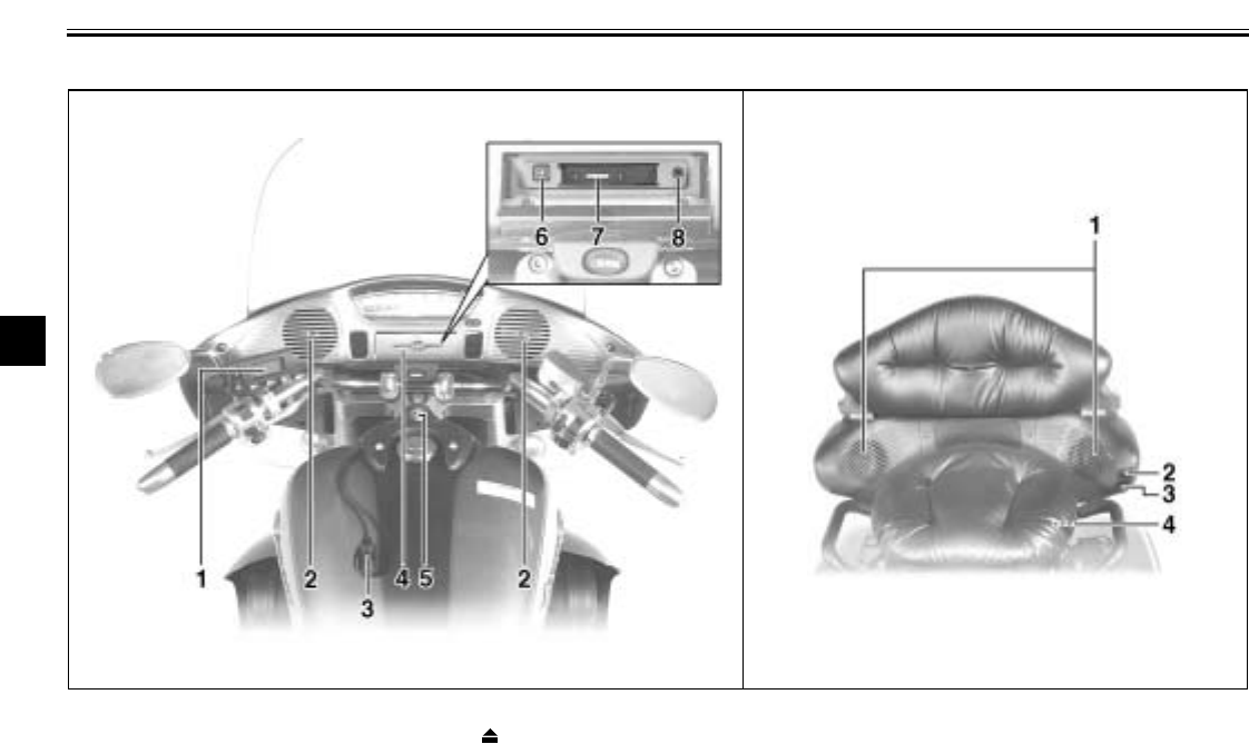
Location of parts
1. Audio system/CB radio control unit
2. Front speaker (× 2)
3. Rider headset jack
4. Cassette deck lid
5. Main switch steering lock
6. Eject (“ ”) button
7. Cassette deck compartment
8. Auxiliary audio input jack
1. Rear speaker (× 2)
2. Passenger volume control knob
3. Passenger “TALK” button
4. Passenger headset jack
AUDIO SYSTEM AND CB RADIO
4-2
4
WARNING
@
●It is dangerous to operate the
audio system controls while
riding. Never take your hands
off the handlebars while riding.
●Keep the volume at a low
enough level to be aware of traf-
fic conditions and ensure safety.
@
CAUTION:
@
●Do not use the audio system or
CB radio for a long period of
time when the engine is not run-
ning as the battery may dis-
charge.
●The control unit, cassette deck
and speakers are water-resis-
tant; however, it is good prac-
tice to cover them with a plastic
bag when washing the motor-
cycle.
●When cleaning the control unit
display, use a neutral detergent.
Never use strong abrasive
cleaning products, fuel (gaso-
line), thinner, etc.
@
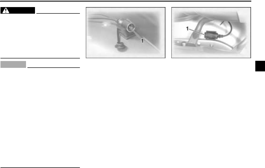
Headsets (optional)
For CB (Citizens Band) radio transmis-
sion, a headset is necessary; however,
CB reception is possible without a
headset. For intercom use, two head-
sets are necessary. Consult a Yamaha
dealer if you wish to obtain headsets.
Connect the headsets to the jacks
shown in the illustrations and make
sure that the headsets are selected as
the output. (See the “Selecting the out-
put” section on page 4-7 for further in-
structions.)
1. Rider headset jack 1. Passenger headset jack
AUDIO SYSTEM AND CB RADIO
4-3
4
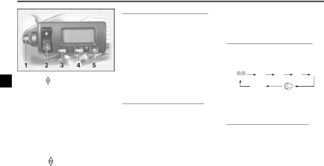
Control unit
Volume control knob
This knob adjusts the audio system vol-
ume, the CB radio reception volume,
and the CB squelch level.
Up/down (“ ”) switch
This switch is used to perform the fol-
lowing operations.
Short push (less than one second)
●Skipping songs on the cassette
tape
●Selecting a preset radio station
●Selecting a track on the optional
CD changer
●Selecting a CB channel
●Adjusting the CB squelch level
●Tuning in a radio station manually
●Adjusting the intercom volume
●Changing the settings in a mode
Long push (one second or more)
●Changing the cassette deck play
direction
●Tuning in a radio station automati-
cally
●Selecting a CD in the optional CD
changer
Audio system button “AUDIO”
This button is used to perform the fol-
lowing operations.
Short push (less than one second)
●Turning on the audio system
●Changing the audio source in the
following sequence
Long push (one second or more)
●Turning off the audio system
1. Volume control knob
2. Up/down (“ ”) switch
3. Audio system button “AUDIO”
4. Selection button “SELECT”
5. CB radio button “CB”
(Tape) FM1 FM2 FM3 AM
AUX (CD changer
*
)
(Auxiliary
audio source)
* The CD mode appears in the display only
when the optional CD changer is installed.
AUDIO SYSTEM AND CB RADIO
4-4
4
Selection button “SELECT”
This button is used to perform the fol-
lowing operations.
Short push (less than two seconds)
●Changing modes in the following
sequence
Audio system
CB radio
●Programming preset radio stations
Long push (two seconds or more)
●Selecting the preset radio station
programming mode
CB radio button “CB”
This button is used to perform the fol-
lowing operations.
Short push (less than one second)
●Turning on the CB radio
●Selecting the squelch level mode
Long push (one second or more)
●Turning off the CB radio
(Output) BASS TREB FAD
(Auto
volume) (Intercom
volume)
Radio
SP/HS (Treble)
frequency
(Fade )
1
2IC
AV
1
2
This mode does not appear in the display when
the headsets are selected as the output.
This mode appears in the display only when one
of the radio frequency bands is selected as the au-
dio source.
IC (Intercom volume)
RB: on/oF (Roger beep)
SP/HS
(Output)
AUDIO SYSTEM AND CB RADIO
4-5
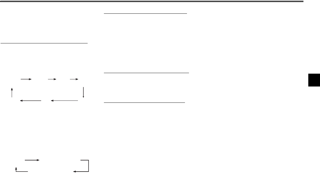
4Making basic settings
Turning on/off the audio system
To turn the power on
1. Make sure that the key is in the
“ACC” or “ON” position.
2. Push the “AUDIO” button once for
less than one second.
To turn the power off
Push the “AUDIO” button once for one
second or more.
Adjusting the audio system volume
Turn the volume control knob until the
desired audio system volume is dis-
played (e.g., “Vo:10”). The audio sys-
tem volume can be set between “0”
and “30”. After the adjustment is made,
the audio system returns to normal op-
eration and the current audio mode ap-
pears in the display.
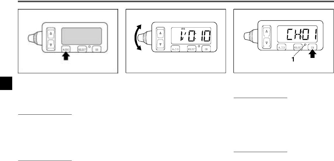
Turning on/off the CB radio
To turn the power on
1. Make sure that the key is in the
“ACC” or “ON” position.
2. Push the “CB” button once for less
than one second. The current CB
channel appears in the display.
To turn the power off
Push the “CB” button once for one sec-
ond or more. The CB indicator light will
go off.
1. CB radio indicator light
AUDIO SYSTEM AND CB RADIO
4-6
4
Adjusting the CB reception volume
Turn the control knob until the desired
CB reception volume is displayed (e.g.,
“Vo:10”). The CB reception volume can
be set between “0” and “20”. After the
adjustment is made, the CB radio re-
turns to normal operation and the CB
channel appears in the display.
Making mode settings
General procedure
The following setting procedure applies
to the audio system, CB radio, and op-
tional CD changer.
NOTE:
@
●In order to make settings in any of
the audio system modes, make
sure that the audio system is se-
lected. If necessary, push the
“AUDIO” button for less than one
second.
●In order to make settings in the CB
radio modes, make sure that the
CB radio is selected. If necessary,
push the “CB” button for less than
one second.
@
1. Repeatedly push the “SELECT”
button for less than one second
until the desired mode appears in
the display. With each press of the
button, the mode changes in the
following sequence.
Audio system
CB Radio
2. While the selected mode is dis-
played (for about five seconds),
repeatedly push either side of the
up/down switch for less than one
second until the desired setting is
displayed.
(Output) BASS TREB FAD
(Auto
volume) (Intercom
volume)
Radio
SP/HS (Treble)
frequency
(Fade )
1
2IC
AV
1
2
This mode does not appear in the display when
the headsets are selected as the output.
This mode appears in the display only when one
of the radio frequency bands is selected as the au
-
dio source.
IC (Intercom volume)
RB: on/oF (Roger beep)
SP/HS
(Output)
AUDIO SYSTEM AND CB RADIO
4-7
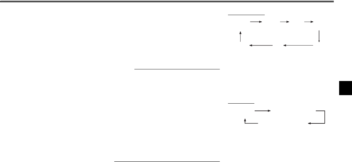
4Selecting the output (speakers or
headsets)
1. Repeatedly push the “SELECT”
button for less than one second
until either “SP” (speakers) or “HS”
and “ ” (headsets) appears in
the display.
2. Push either side of the up/down
switch for less than one second to
change the setting.
NOTE:
@
The speakers and headsets cannot be
used at the same time.
@
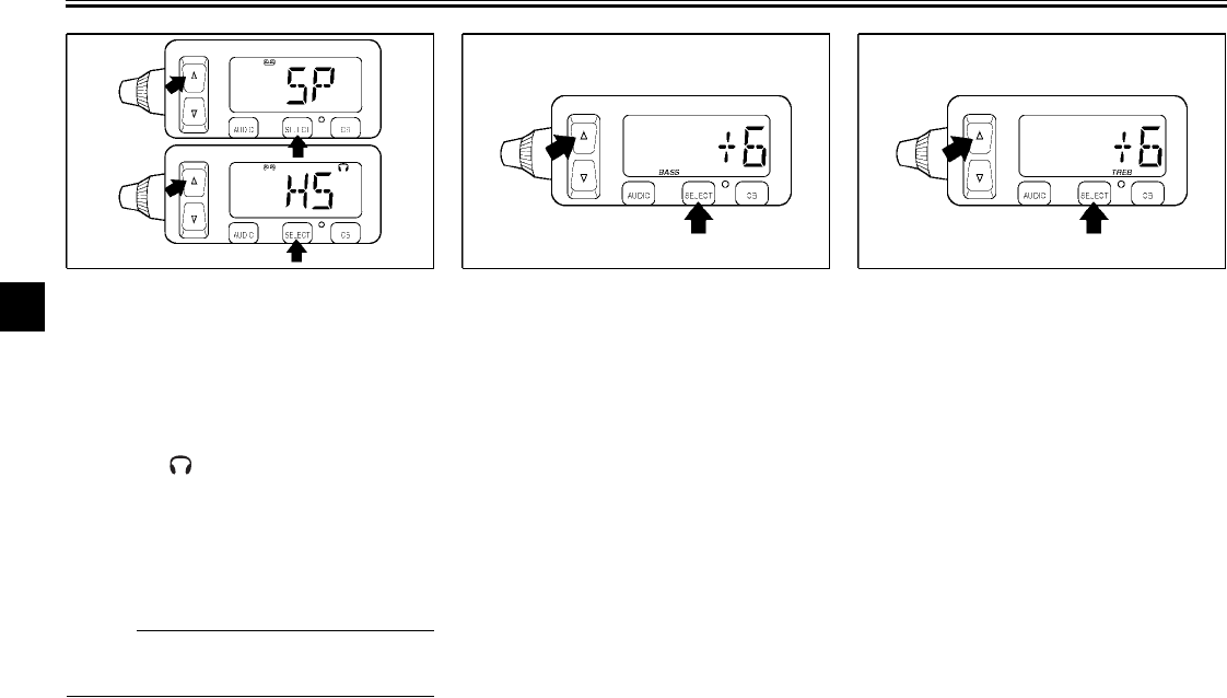
Adjusting the bass level
1. Repeatedly push the “SELECT”
button for less than one second
until “BASS” appears at the bot-
tom of the display.
2. Repeatedly push either side of the
up/down switch for less than one
second until the desired level is
displayed. The bass level can be
set between “–6” and “+6”.
Adjusting the treble level
1. Repeatedly push the “SELECT”
button for less than one second
until “TREB” appears at the bot-
tom of the display.
2. Repeatedly push either side of the
up/down switch for less than one
second until the desired level is
displayed. The treble level can be
set between “–6” and “+6”.
AUDIO SYSTEM AND CB RADIO
4-8
4
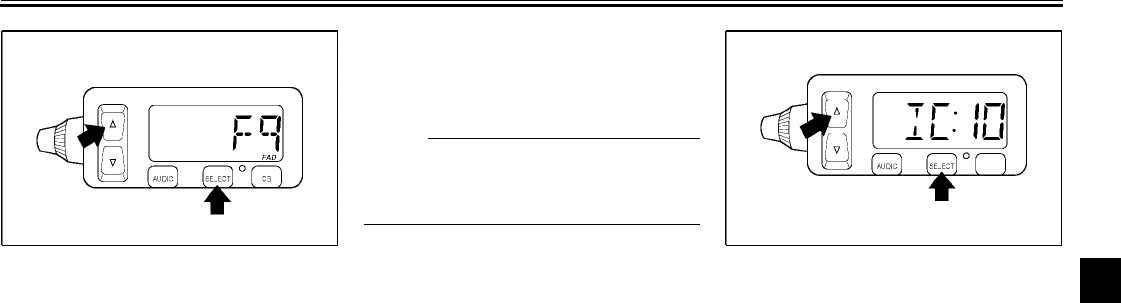
Adjusting the fade level (balance
between front and rear speakers)
1. Make sure that the speakers are
selected as the output source.
(See the “Selecting the output”
section on page 4-7 for selection
procedures.)
2. Repeatedly push the “SELECT”
button for less than one second
until “FAD” appears at the bottom
of the display.
3. Repeatedly push either side of the
up/down switch for less than one
second until the desired level is
displayed. The fade level can be
set between “F9” (front speakers
only) and “R9” (rear speakers
only).
NOTE:
@
When the fade level is set to “0”, the
front and rear speaker levels are the
same.
@
Adjusting the intercom volume
1. Repeatedly push the “SELECT”
button for less than one second
until the intercom volume (e.g.,
“IC:10”) appears in the display.
2. Repeatedly push either side of the
up/down switch for less than one
second until the desired volume is
displayed. The intercom volume
can be set between “0” and “20”.
AUDIO SYSTEM AND CB RADIO
4-9
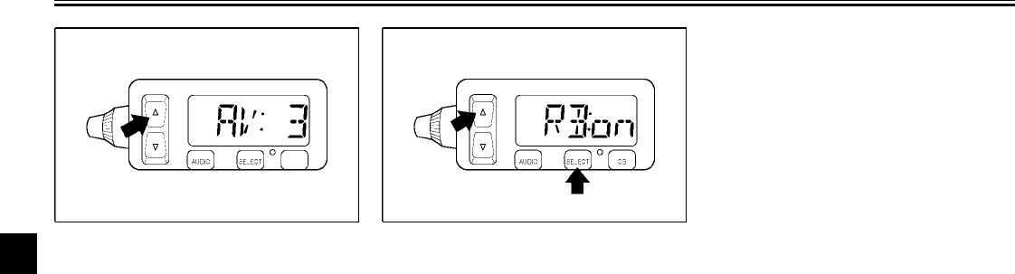
4Adjusting the auto volume
When riding the motorcycle, external
noise may override the audio system
output volume. The audio system fea-
tures an automatic volume control
function which compensates for exter-
nal noise.
1. Repeatedly push the “SELECT”
button for less than one second
until the auto volume (e.g.,
“AV: 3”) appears in the display.
2. Repeatedly push either side of the
up/down switch for less than one
second until the desired volume is
displayed. The auto volume can
be set between “0” and “5”.
Turning on/off the CB roger beep
1. Repeatedly push the “SELECT”
button for less than one second
until either “RB:on” (roger beep
on) or “RB:oF” (roger beep off) ap-
pears in the display.
2. Repeatedly push either side of the
up/down switch for less than one
second to change the setting.
Intercom operation
Provided both the rider and passenger
are wearing headsets, they can talk to
each other through the intercom at any
time. (See the “Adjusting the intercom
volume” section on page 4-8 for adjust-
ment procedures.)
AUDIO SYSTEM AND CB RADIO
4-10
4
Cassette deck operation
WARNING
@
●It is dangerous to operate the
cassette deck while riding. Nev-
er take your hands off the han-
dlebars while riding.
●Keep the volume at a low
enough level to be aware of traf-
fic conditions and ensure safe-
ty.
@
CAUTION:
@
●Keep the cassette deck lid
closed at all times, except when
inserting or removing a cas-
sette.
●Do not leave cassette tapes in
direct sunlight for a long period
of time.
●Do not allow the inside of the
cassette deck to get wet. If this
happens, keep the cassette
deck lid open and dry out the
deck in the shade.
●To clean the tape head, use a
de-magnetizing cleaning cas-
sette, but be sure to turn the
volume all the way down to
avoid speaker damage.
@
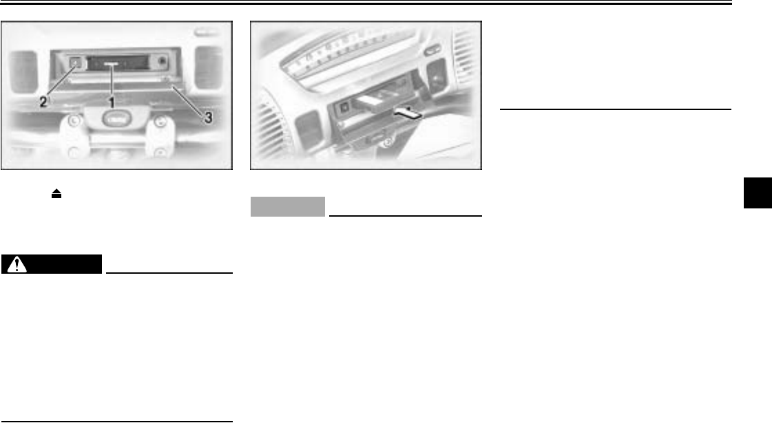
1. Cassette deck compartment
2. Eject (“ ”) button
3. Cassete deck lid
AUDIO SYSTEM AND CB RADIO
4-11
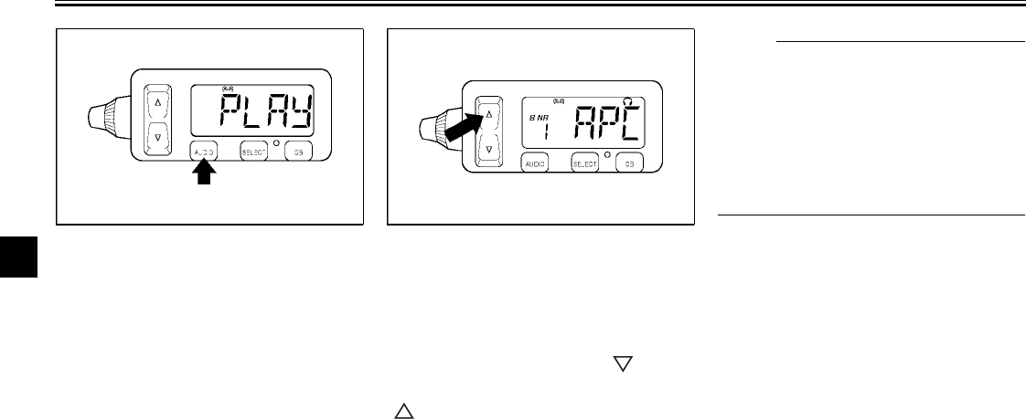
4Playing a cassette tape
1. Make sure that the audio system is
turned on. (See page 4-3.)
2. Insert a cassette tape into the cas-
sette compartment as shown.
“LOAD”, then “PLAY” appears in
the display. (If a cassette is al-
ready inserted, push the “AUDIO”
button until “PLAY” appears in the
display.) The tape starts playing.
Skipping songs
While a cassette tape is playing, push
either side of the up/down switch once
for less than one second for each song
to be skipped. Pushing “ ” skips
songs in the forward direction. Pushing
“” skips songs in the reverse direc-
tion. “APC” (auto program control) and
the number of songs to be skipped
(e.g., “3”) appear in the display. When
skipping songs in reverse, a minus sign
appears in front of the number of songs
to be skipped (e.g., “–2”). (“–1” indi-
cates that the current song will be
played again.)
NOTE:
@
●The maximum number of songs
that can be skipped in either direc-
tion is 9.
●To stop skipping songs, push the
up/down switch in the opposite di-
rection that songs are being
skipped.
@
AUDIO SYSTEM AND CB RADIO
4-12
4
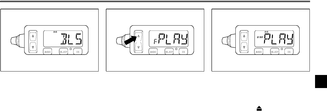
Skipping a blank
When there is a long blank portion of
tape on the cassette, “BLS” appears in
the display and the cassette deck auto-
matically fast-forwards the tape to the
next song.
Changing the tape play direction
While the cassette tape is playing,
push either side of the up/down switch
for more than one second to reverse
the play direction. “F” appears in the
display when the tape is played in the
forward direction. “R” appears in the
display when the tape is played in the
reverse direction.
Turning on/off the Dolby noise
reduction system
While the cassette tape is playing,
push the eject (“ ”) button for more
than two seconds to turn the Dolby B
noise reduction system on or off.
“B NR” appears in the display when the
noise reduction system is turned on.
AUDIO SYSTEM AND CB RADIO
4-13
4
NOTE:
@
●The Dolby noise reduction system
has been manufactured under li-
cense from Dolby Laboratories Li-
censing Corporation.
●Dolby and the double “D” symbol
are registered trademarks of Dol-
by Laboratories Licensing Corpo-
ration.
@
Ejecting the cassette tape
Push the eject (“ ”) button to eject the
tape from the cassette deck. “EJCT”
appears in the display, and then
“CASS” starts flashing.
Radio operation
WARNING
@
●It is dangerous to operate the
radio while riding. Never take
your hands off the handlebars
while riding.
●Keep the volume at a low
enough level to be aware of traf-
fic conditions and ensure safe-
ty.
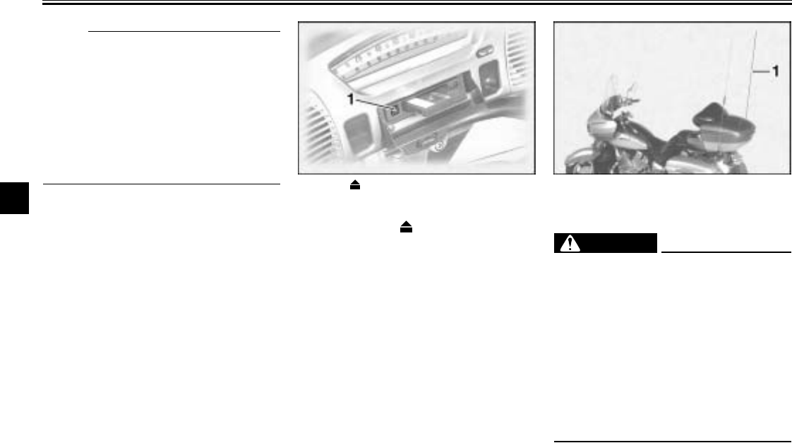
●Never ride the motorcycle with
the radio antenna folded down.
@
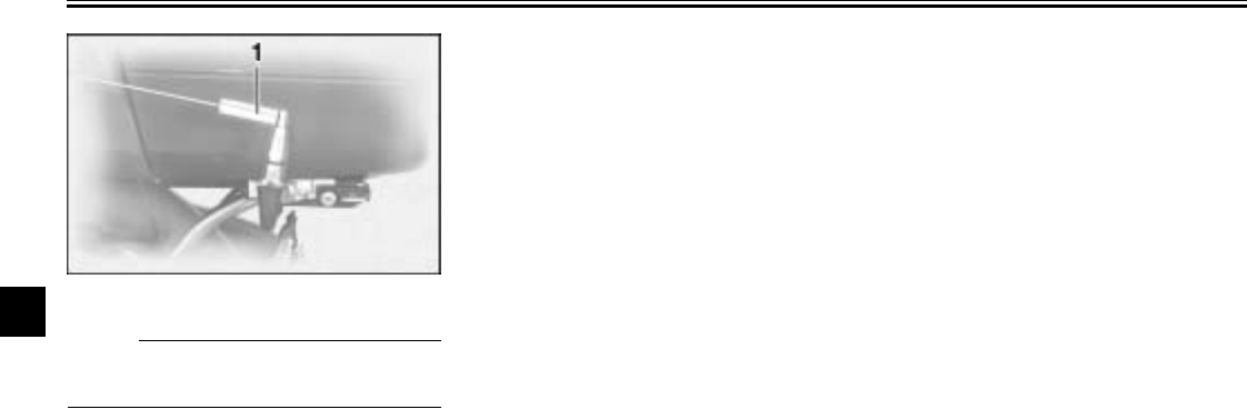
1. Eject (“ ”) button 1. Radio antenna
AUDIO SYSTEM AND CB RADIO
4-14
4
NOTE:
@
●The antenna can be folded down
after lifting the sleeve.
●Be sure to tighten the antenna nut
securely when putting the antenna
back to the original position.
@
Selecting a frequency band
This radio offers three FM bands and
one AM band. Since all three FM
bands cover the whole FM frequency
range, any one of them can be select-
ed for tuning in an FM station. These
three FM bands are useful for catego-
rizing FM preset stations. Repeatedly
push the “AUDIO” button for less than
one second until the desired frequency
band appears in the display.
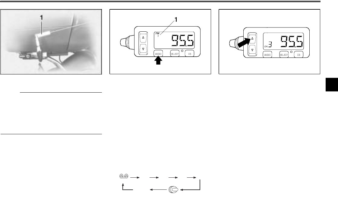
Tuning in a radio station automati-
cally
1. Select a frequency band.
2. Push either side of the up/down
switch once for one second or
more. The radio automatically
tunes in the first station that has a
strong enough signal to be re-
ceived.
1. Sleeve 1. Frequency band
(Tape) FM1 FM2 FM3 AM
AUX (CD changer
*
)
(Auxiliary
audio source)
* The CD mode appears in the display only
when the optional CD changer is installed.
AUDIO SYSTEM AND CB RADIO
4-15
4Tuning in a radio station manually
In order to tune in a particular radio sta-
tion (e.g., when the signal is too weak
for automatic tuning), the radio fre-
quency can be selected manually as
follows.
1. Select a frequency band. (See
page 4-14.)
2. Repeatedly push the “SELECT”
button for less than one second
until the currently selected radio
frequency appears in the display.
3. Push either side of the up/down
switch for less than one second
until the desired frequency is dis-
played. The frequency changes
in 0.2-MHz steps for FM and in
10-kHz steps for AM.
Tuning in a preset radio station
1. Select a frequency band. (See
page 4-14.)
2. Repeatedly push either side of the
up/down switch for less than one
second until the desired preset
station number is displayed.
NOTE:
@
To be able to tune in a preset radio sta-
tion, you must have previously pro-
grammed at least one. (See the
following sections.)
@
1. Preset station number
AUDIO SYSTEM AND CB RADIO
4-16
4
Programing preset radio stations
manually
Up to six stations can be programmed
for each frequency band (FM1, FM2,
FM3, and AM) using either manual or
automatic tuning.
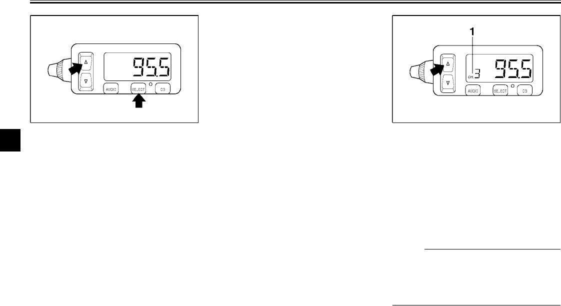
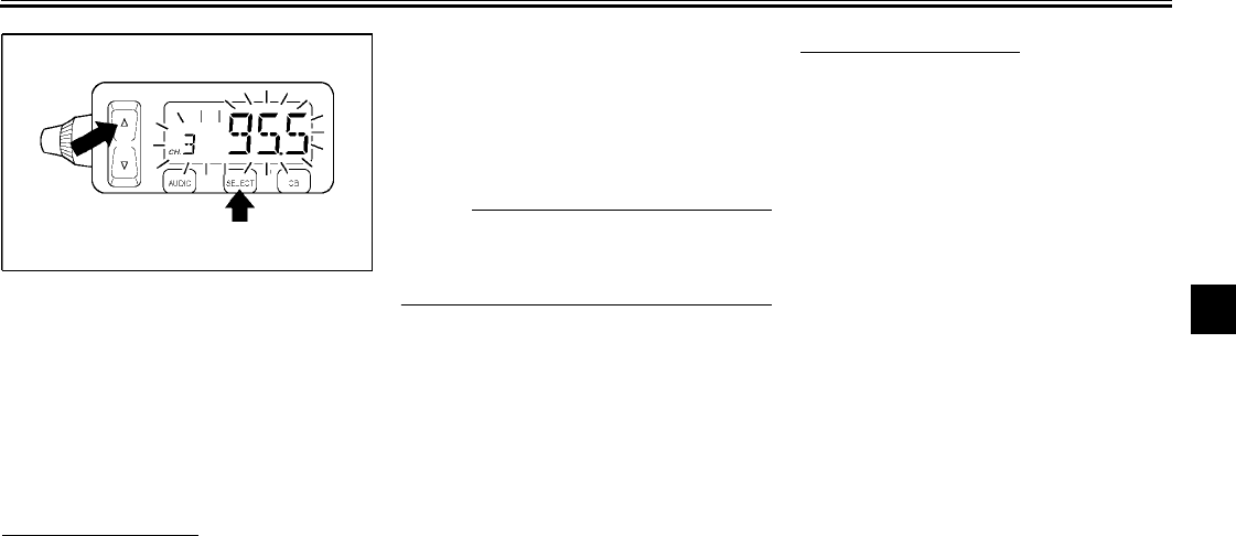
Using manual tuning
1. Manually tune in a radio station
that you wish to preset. (See page
4-15.)
2. Push the “SELECT” button once
for two seconds or more. The ra-
dio frequency and preset station
number “1” (to the right of “CH.”)
start flashing.
3. Repeatedly push either side of the
up/down switch for less than one
second until the desired preset
number (“1” through “6”) is dis-
played.
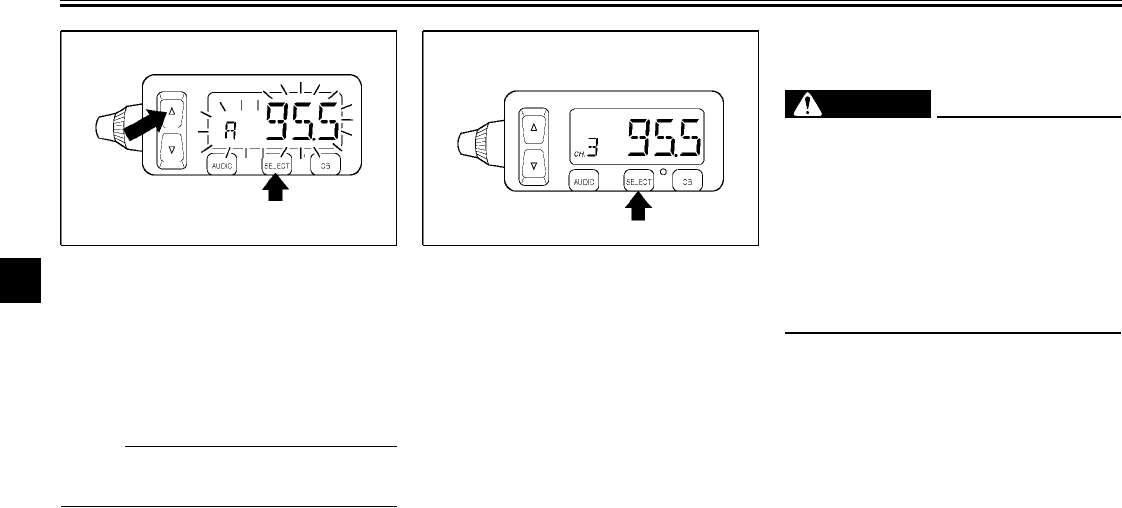
NOTE:
@
Selecting “A” will automatically pro-
gram the preset stations. See the fol-
lowing section.
@
4. Push the “SELECT” button once
for less than one second to store
the radio station selected in step 1
under the preset number selected
in step 3.
5. Repeat this procedure to preset
other radio stations.
Using automatic tuning
1. Select a frequency band. (See
page 4-14.)
2. Push the “SELECT” button once
for two seconds or more. The ra-
dio frequency and preset station
number “1” (to the right of “CH.”)
start flashing.
3. Push either side of the up/down
switch once for one second or
more to tune in a station automati-
cally.
4. Repeatedly push either side of the
up/down switch for less than one
second until the desired preset
number (“1” through “6”) is dis-
played.
5. Push the “SELECT” button once
for less than one second to store
the radio station selected in step 3
under the preset number selected
in step 4.
6. Repeat this procedure to preset
other radio stations.
AUDIO SYSTEM AND CB RADIO
4-17
4Programing preset radio stations
automatically
Up to six stations can be programmed
automatically for each frequency band
(FM1, FM2, FM3, and AM) as follows.
NOTE:
@
This function works best in areas with
strong radio signals.
@
1. Select a frequency band. (See
page 4-14.)
2. Push the “SELECT” button once
for two seconds or more. The ra-
dio frequency and preset station
number “1” (to the right of “CH.”)
start flashing.
3. Repeatedly push either side of the
up/down switch for less than one
second until “A” (automatic) ap-
pears in the display.
4. Push the “SELECT” button once
for less than one second to pro-
gram preset radio stations auto-
matically.
Optional CD changer
operation
WARNING
@
●It is dangerous to operate the
CD changer while riding. Never
take your hands off the handle-
bars while riding.
●Keep the volume at a low
enough level to be aware of traf-
fic conditions and ensure safe-
ty.
@
An optional six-disc CD changer can be
mounted in the travel trunk. Ask a
Yamaha dealer to install the genuine
Clarion CDC635 model.
AUDIO SYSTEM AND CB RADIO
4-18
4
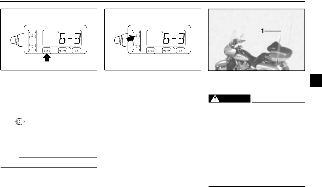
Playing a CD
1. Insert up to six CDs into the CD
changer. Follow the manufactur-
er’s directions.
2. Push the “AUDIO” button until
“” as well as the CD number
and track number (e.g., “6-3”) ap-
pear in the display. The CD starts
playing.
NOTE:
@
“6-3” indicates track no. 3 on CD no. 6.
@
Selecting a CD
Repeatedly push either side of the up/
down switch for one second or more
until the number for the desired CD ap-
pears in the display.
Selecting a CD track
Repeatedly push either side of the up/
down switch for less than one second
until the number for the desired CD
track appears in the display.
CB radio operation
WARNING
@
●It is dangerous to change CB ra-
dio channels or adjust the vol-
ume while riding. Never take
your hands off the handlebars
while riding.
●Keep the volume at a low
enough level to be aware of traf-
fic conditions and ensure safe-
ty.
●Never ride the motorcycle with
the CB antenna folded down.
@
1. CB antenna
AUDIO SYSTEM AND CB RADIO
4-19
4NOTE:
@
The antenna can be folded down after
lifting the sleeve.
@
This CB radio will operate on any of the
40 frequencies designated as Citizens
band channels by the Federal Commu-
nications Commission (F.C.C.). This
model features a frequency-synthesiz-
ing circuit with PHASE LOCK LOOP
technology to assure ultraprecise fre-
quency control. This radio has been
Type-Accepted and Type-Certified by
the F.C.C.
The Citizens Band Radio Service is
under the jurisdiction of the Feder-
al Communications Commission
(F.C.C.). Any adjustments or modi-
fications which would alter the per-
formance of the transceiver’s
original F.C.C. Type Acceptance or
which would change the frequen-
cy-determining method are strictly
prohibited. Replacement or substi-
tution of Crystals, Transistors, IC,
Regulator Diodes or any other part
of unique nature with parts other
than those recommended may
cause violation of the technical
regulation of Part 95 of the F.C.C.
Rules or Violation of Type Accep-
tance requirements of Part 2 of the
Rules.
Elimination of licensing
The Federal Communications Commis-
sion (F.C.C.) has ruled that Citizens
Band Radio Service Operators no long-
er are required to obtain an F.C.C. li-
cense to operate their CB equipment. In
doing so, the F.C.C. also decided to
permit CB station operation without sta-
tion identification. Elimination of individ-
ual station license results in no
lessening of the operating privileges or
responsibilities of CB users. An opera-
tor of a CB radio station is still required
to comply with the Communications Act
and with the rules of CB Radio Service.
CB radio functions
The CB radio is capable of the follow-
ing functions, which are further ex-
plained in the following sections:
●Selecting a CB channel for trans-
mitting or receiving
●Adjusting the squelch level
●Adjusting the receiving volume
level
●Transmitting and receiving
1. Sleeve
AUDIO SYSTEM AND CB RADIO
4-20
4
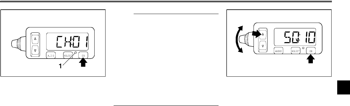
Selecting a CB channel
1. Make sure that the CB radio is
turned on and is selected. (See
pages 4-5 and 4-6.)
2. Repeatedly push either side of the
up/down switch for less than one
second until the desired CB chan-
nel (“Ch:01” through “Ch:40”) is
displayed.
NOTE:
@
All channels, except channel 9, may be
used for communications between sta-
tions operating under different licens-
es. Channel 9 has been reserved by
the F.C.C. for emergency communica-
tions involving the immediate safety of
individuals or immediate protection of
property. Channel 9 may also be used
to render assistance to a motorist. This
is an F.C.C. rule and applies to all oper-
ators of CB radios.
@
Adjusting the squelch level
The squelch is a noise suppresser de-
signed to reduce or eliminate back-
ground noise in the absence of an
incoming signal. The squelch level can
be adjusted as follows.
1. Push the “CB” button once for less
than one second. The squelch lev-
el appears in the display (e.g.,
“SQ:10”).
1. CB radio indicator light
AUDIO SYSTEM AND CB RADIO
4-21
4
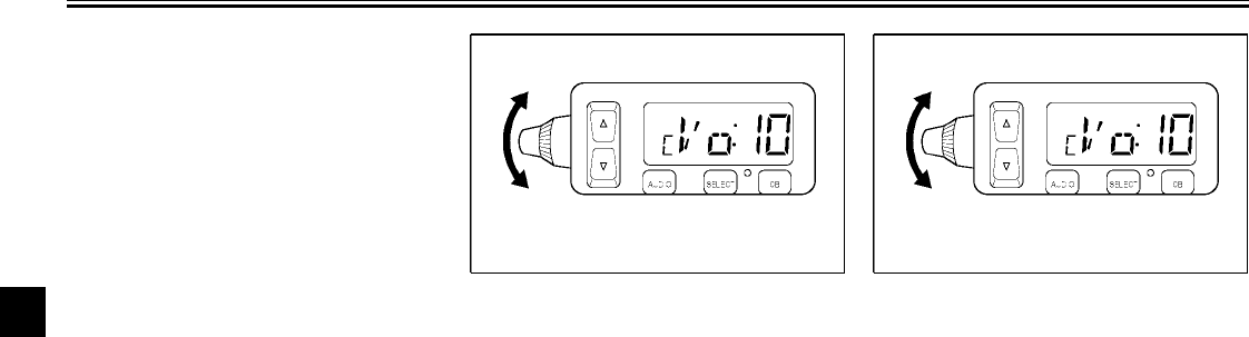
2. Repeatedly push either side of the
up/down switch for less than one
second or turn the control knob
until the desired squelch level is
displayed. The squelch level can
be set between “1” and “20”. After
the adjustment is made, the CB ra-
dio returns to normal operation
and the CB channel appears in the
display. For maximum reception sensitivity, the
squelch level should be set by turning
the control knob fully counterclockwise,
and then slowly turning it clockwise un-
til the background noise has been suffi-
ciently reduced. In order for an
incoming CB signal to be heard, it must
be stronger than the noise received.
Turning the control further clockwise
will increase the threshold level that a
signal must overcome in order to be
heard. Only strong signals will be heard
at the maximum setting.
Adjusting the receiving volume
Turn the volume control knob to
change the receiving volume level of
the CB radio After setting the level, the
display will automatically change back
to the “CB” mode and the channel will
appear. The volume level can be set
between “0” and “20”.
AUDIO SYSTEM AND CB RADIO
4-22
4
Channel information
NOTE:
@
This radio has been designed for operation in the 11-meter Citizens Band Radio Service. It uses a frequency-synthesizing
circuit with Phase-Locked Loop (PLL) technology to provide crystal-controlled transmit and receive operation on all 40 chan-
nels. The PLL circuitry assures ultraprecise frequency control and is designed to meet the Federal Communications Com-
mission requirements applicable to equipment operating in the Citizens Radio Service; it is not to be used for any other
purpose.
@
Channel Channel Frequency in MHz Channel Channel Frequency in MHz
126.965 21 27.215
226.975 22 27.225
336.985 23 27.235
427.005 24 27.245
527.015 25 27.255
627.025 26 27.265
727.035 27 27.275
827.055 28 27.285
927.065 29 27.295
10 27.075 30 27.305
11 27.085 31 27.315
12 27.105 32 27.325
13 27.115 33 27.335
14 27.125 34 27.345
15 27.135 35 27.355
16 27.155 36 27.365
17 27.165 37 27.375
18 27.175 38 27.385
19 27.185 39 27.395
20 27.205 40 27.405
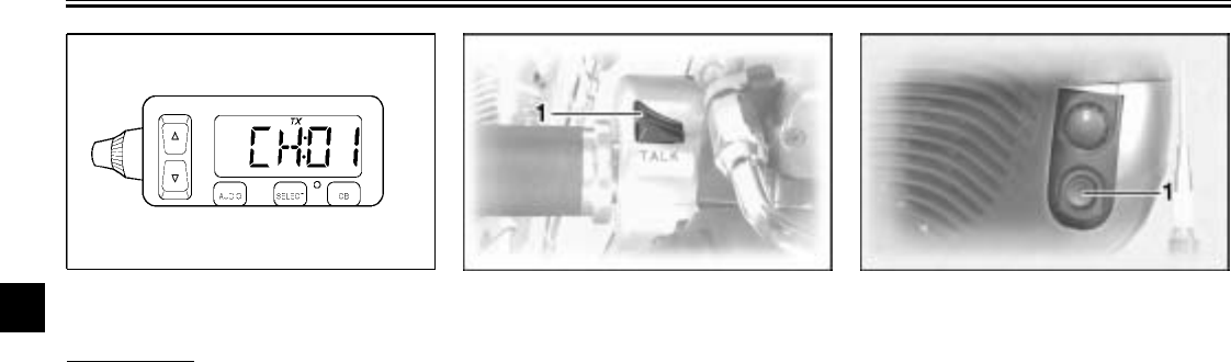
AUDIO SYSTEM AND CB RADIO
4-23
4Transmitting and receiving
Transmission
Push the rider “TALK” switch or the
passenger “TALK” button to transmit.
“TX” appears in the display.
1. “TALK” switch 1. Passenger “TALK” button
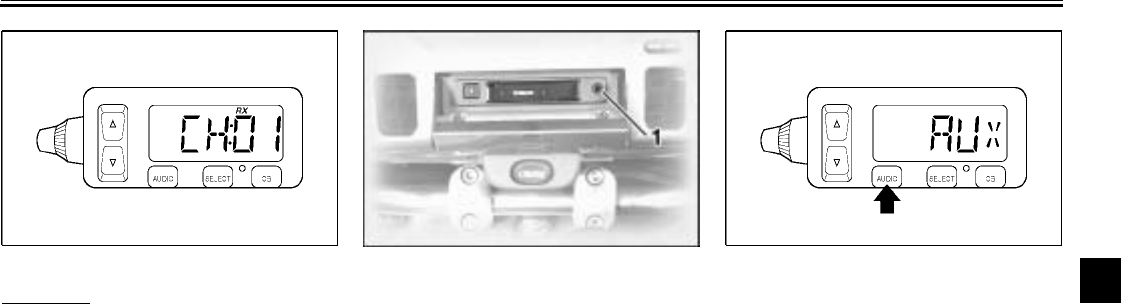
AUDIO SYSTEM AND CB RADIO
4-24
4
Reception
“RX” appears in the display when the
CB radio is receiving a signal.
Auxiliary audio source
operation
Auxiliary audio equipment can be con-
nected to, and played through, the au-
dio system.
1. Insert the output plug of the auxil-
iary equipment into the jack locat-
ed at the right of the cassette
deck.
2. Repeatedly push the “AUDIO” but-
ton for less than one second until
“AUX” appears in the display. The
auxiliary equipment can now be
played through the audio system.
1. Auxiliary audio input jack

PRE-OPERATION CHECKS
5
Pre-operation check list ..................................................................... 5-1
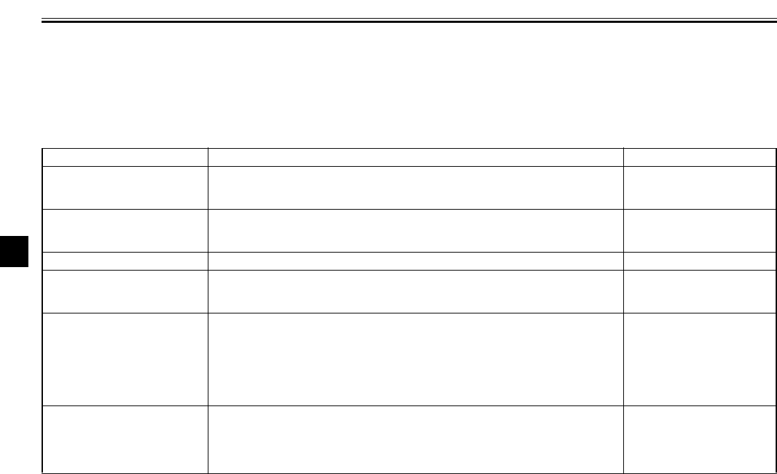
5-1
5
EAU01114
5-
PRE-OPERATION CHECKS
The condition of a vehicle is the owner’s responsibility. Vital components can start to deteriorate quickly and unexpectedly,
even if the vehicle remains unused (for example, as a result of exposure to the elements). Any damage, fluid leakage or loss
of tire air pressure could have serious consequences. Therefore, it is very important, in addition to a thorough visual inspec-
tion, to check the following points before each ride.
EAU03439
Pre-operation check list
ITEM CHECKS PAGE
Fuel •Check fuel level in fuel tank.
•Refuel if necessary.
•Check fuel line for leakage. 3-11
Engine oil •Check oil level in engine.
•If necessary, add recommended oil to specified level.
•Check vehicle for oil leakage. 7-13–7-16
Final gear oil •Check vehicle for oil leakage. 7-16
Coolant •Check coolant level in reservoir.
•If necessary, add recommended coolant to specified level.
•Check cooling system for leakage. 7-16–7-18
Front brake
•Check operation.
•If soft or spongy, have Yamaha dealer bleed hydraulic system.
•Check lever free play.
•Adjust if necessary.
•Check fluid level in reservoir.
•If necessary, add recommended brake fluid to specified level.
•Check hydraulic system for leakage.
7-26, 7-28–7-30
Rear brake
•Check operation.
•If soft or spongy, have Yamaha dealer bleed hydraulic system.
•Check fluid level in reservoir.
•If necessary, add recommended brake fluid to specified level.
•Check hydraulic system for leakage.
7-27–7-30
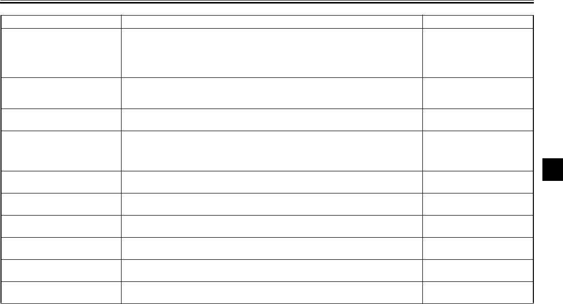
PRE-OPERATION CHECKS
5-2
5
Clutch
•Check operation.
•If soft or spongy, have Yamaha dealer bleed hydraulic system.
•Check fluid level in reservoir.
•If necessary, add recommended fluid to specified level.
•Check hydraulic system for leakage.
7-26, 7-29
Throttle grip •Make sure that operation is smooth.
•Check free play.
•If necessary, have Yamaha dealer make adjustment or lubricate. 7-21
Control cables •Make sure that operation is smooth.
•Lubricate if necessary. —
Wheels and tires
•Check for damage.
•Check tire condition and tread depth.
•Check air pressure.
•Correct if necessary.
7-21–7-25
Brake and shift pedals •Make sure that operation is smooth.
•Lubricate pedal pivoting points if necessary. 7-31
Brake and clutch levers •Make sure that operation is smooth.
•Lubricate lever pivoting points if necessary. 7-31
Sidestand •Make sure that operation is smooth.
•Lubricate pivot if necessary. 7-32
Chassis fasteners •Make sure that all nuts, bolts and screws are properly tightened.
•Tighten if necessary. —
Instruments, lights, signals
and switches •Check operation.
•Correct if necessary. 7-37–7-38
Sidestand switch •Check operation of ignition circuit cut-off system.
•If system is defective, have Yamaha dealer check vehicle. 3-19
ITEM CHECKS PAGE
PRE-OPERATION CHECKS
5-3
5
NOTE:
@
Pre-operation checks should be made each time the motorcycle is used. Such an inspection can be accomplished in a very
short time; and the added safety it assures is more than worth the time involved.
@
EWA00033
WARNING
@
If any item in the Pre-operation check list is not working properly, have it inspected and repaired before operating
the motorcycle.
@

OPERATION AND IMPORTANT RIDING POINTS
6
Starting and warming up a cold engine ............................................. 6-2
Starting a warm engine ..................................................................... 6-4
Shifting .............................................................................................. 6-4
Engine break-in ................................................................................. 6-6
Parking .............................................................................................. 6-7
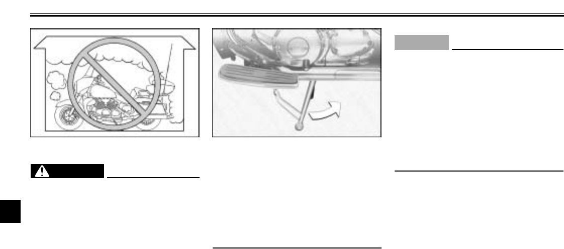
6-1
6
EAU00372
6-
OPERATION AND IMPORTANT RIDING POINTS
EAU00373
WARNING
@
●Become thoroughly familiar
with all operating controls and
their functions before riding.
Consult a Yamaha dealer re-
garding any control or function
that you do not thoroughly un-
derstand.
●Never start the engine or operate
it in a closed area for any length
of time. Exhaust fumes are poi-
sonous, and inhaling them can
cause loss of consciousness
and death within a short time. Al-
ways make sure that there is ad-
equate ventilation.
●Before starting out, make sure
that the sidestand is up. If the
sidestand is not raised com-
pletely, it could contact the
ground and distract the opera-
tor, resulting in a possible loss
of control.
@
EAU00376
CAUTION:
@
●Make sure not to store personal
items near the air cleaner in-
take, otherwise air intake will be
blocked and performance will
suffer.
●Make sure not to put anything
near the battery and its termi-
nals, otherwise electrical failure
and acid corrosion may result.
@
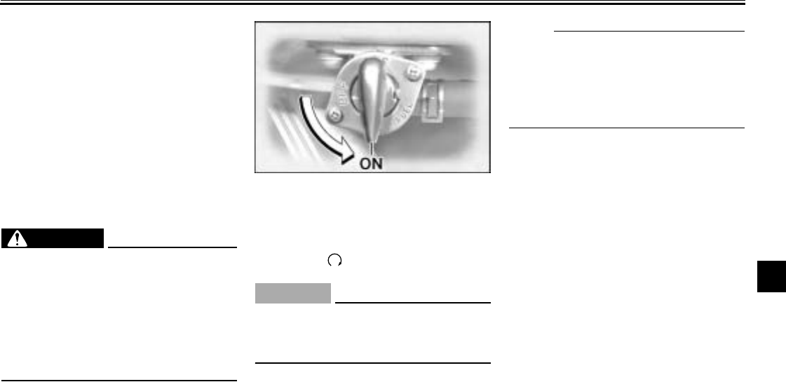
OPERATION AND IMPORTANT RIDING POINTS
6-2
6
EAU01789*
Starting and warming up a
cold engine
In order for the ignition circuit cut-off
system to enable starting, one of the
following conditions must be met:
●The transmission is in the neutral
position.
●The transmission is in gear with
the clutch lever pulled and the
sidestand up.
EW000054
WARNING
@
●Before starting the engine,
check the function of the igni-
tion circuit cut-off system ac-
cording to the procedure
described on page 3-21.
●Never ride with the sidestand
down.
@
1. Turn the fuel cock lever to “ON”.
2. Turn the key to “ON” and make
sure that the engine stop switch is
set to “ ”.
EC000035
CAUTION:
@
If the fuel level warning light comes
on, check the fuel level, and, if nec-
essary, refuel as soon as possible.
@
3. Shift the transmission into the neu-
tral position.
NOTE:
@
When the transmission is in the neutral
position, the neutral indicator light
should be on, otherwise have a
Yamaha dealer check the electrical cir-
cuit.
@
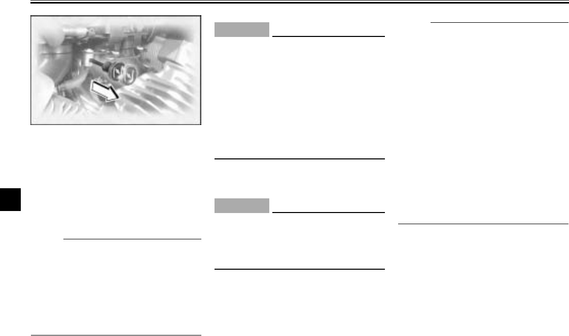
OPERATION AND IMPORTANT RIDING POINTS
6-3
6
4. Turn the starter (choke) on and
completely close the throttle. (See
page 3-13 for starter (choke) oper-
ation.)
5. Start the engine by pushing the
start switch.
NOTE:
@
If the engine fails to start, release the
start switch, wait a few seconds, and
then try again. Each starting attempt
should be as short as possible to pre-
serve the battery. Do not crank the en-
gine more than 10 seconds on any one
attempt.
@
ECA00031
CAUTION:
@
The engine trouble warning light
should come on when the start
switch is pushed, and it should go
off when the start switch is released.
If the engine trouble warning does
not come on when pushing the start
switch, or it remains on after start-
ing, have a Yamaha dealer check the
self-diagnosis device.
@
6. After starting the engine, move the
starter (choke) knob back halfway.
ECA00055
CAUTION:
@
For maximum engine life, always
warm the engine up before starting
off. Never accelerate hard when the
engine is cold!
@
7. When the engine is warm, turn the
starter (choke) off.
NOTE:
@
The engine is warm when it responds
normally to the throttle with the starter
(choke) turned off. To avoid the possi-
bility of excessive exhaust emissions,
never leave the starter (choke) on long-
er than necessary. The time necessary
for starter (choke) use depends upon
the ambient temperature. Tempera-
tures above 50°F (10°C) require about
7 seconds of starter (choke) use and
temperatures below 50°F (10°C) re-
quire about 35 seconds with the starter
(choke) turned on, then about 2.5 min-
utes with the starter (choke) in the half-
way position.
@
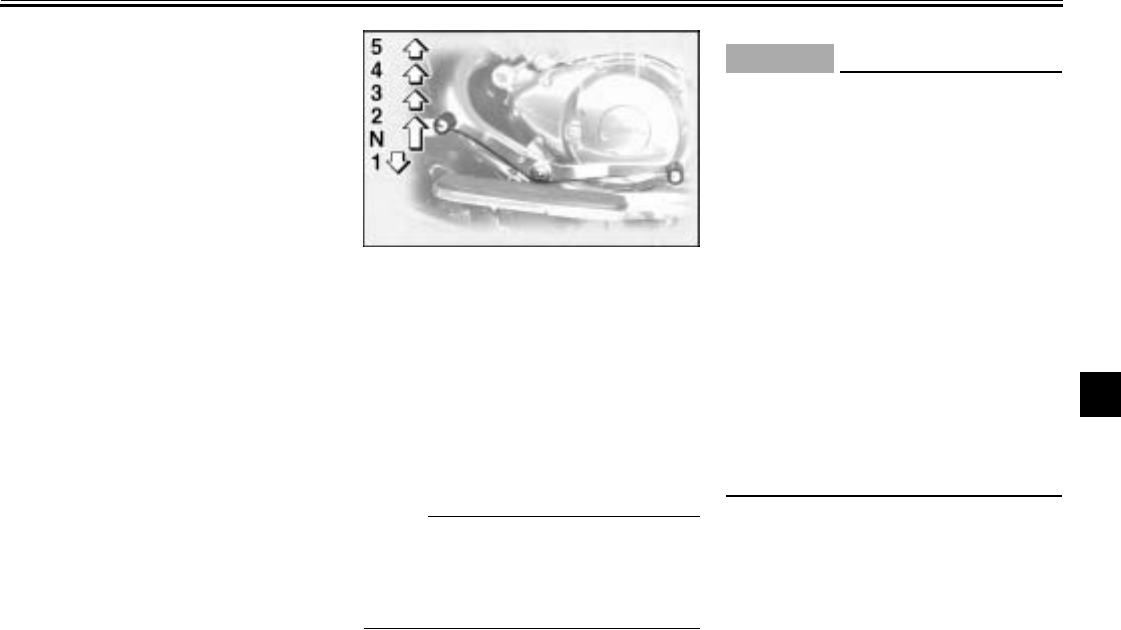
OPERATION AND IMPORTANT RIDING POINTS
6-4
6
EAU01258
Starting a warm engine
Follow the same procedure as for start-
ing a cold engine with the exception
that the starter (choke) is not required
when the engine is warm.
EAU00423
Shifting
Shifting gears lets you control the
amount of engine power available for
starting off, accelerating, climbing hills,
etc.
The gear positions are shown in the il-
lustration.
NOTE:
@
To shift the transmission into the neu-
tral position, press the shift pedal down
repeatedly until it reaches the end of its
travel, and then slightly raise it.
@
EC000048
CAUTION:
@
●Even with the transmission in
the neutral position, do not
coast for long periods of time
with the engine off, and do not
tow the motorcycle for long dis-
tances. The transmission is
properly lubricated only when
the engine is running. Inade-
quate lubrication may damage
the transmission.
●Always use the clutch while
changing gears to avoid dam-
aging the engine, transmission,
and drive train, which are not
designed to withstand the
shock of forced shifting.
@
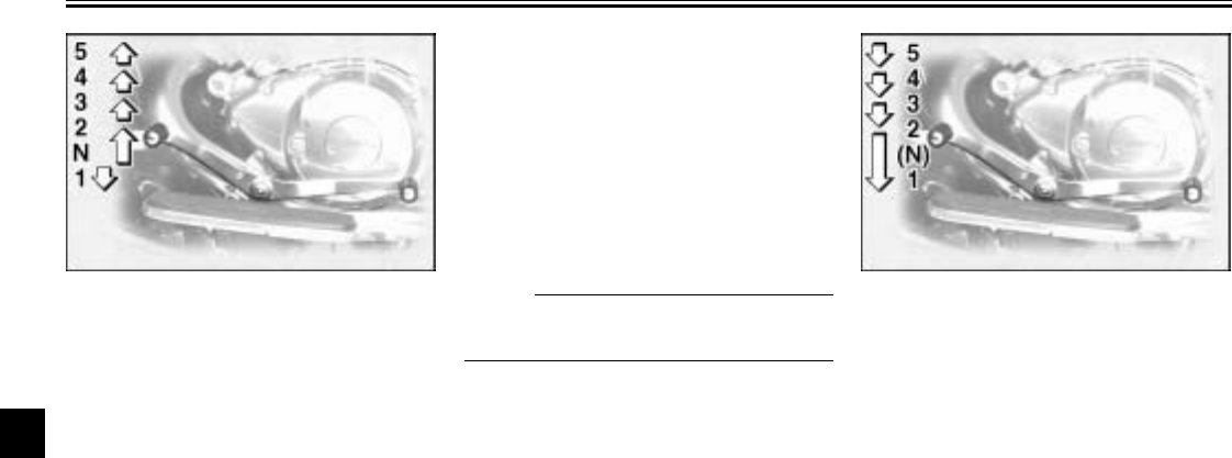
OPERATION AND IMPORTANT RIDING POINTS
6-5
6
EAU02988
To start out and accelerate
1. Pull the clutch lever to disengage
the clutch.
2. Shift the transmission into first
gear. The neutral indicator light
should go out.
3. Open the throttle gradually, and at
the same time, release the clutch
lever slowly.
4. At the recommended shift points
shown in the table on page 6-6,
close the throttle, and at the same
time, quickly pull the clutch lever
in.
5. Shift the transmission into second
gear. (Make sure not to shift the
transmission into the neutral posi-
tion.)
6. Open the throttle part way and
gradually release the clutch lever.
7. Follow the same procedure when
shifting to the next higher gear.
NOTE:
@
Always shift gears at the recommend-
ed shift points.
@
EAU00427
To decelerate
1. Apply both the front and the rear
brakes to slow the motorcycle.
2. Shift the transmission into first
gear when the motorcycle reaches
25 mi/h (16 km/h). If the engine is
about to stall or runs very roughly,
pull the clutch lever in and use the
brakes to stop the motorcycle.
3. Shift the transmission into the neu-
tral position when the motorcycle
is almost completely stopped. The
neutral indicator light should come
on.
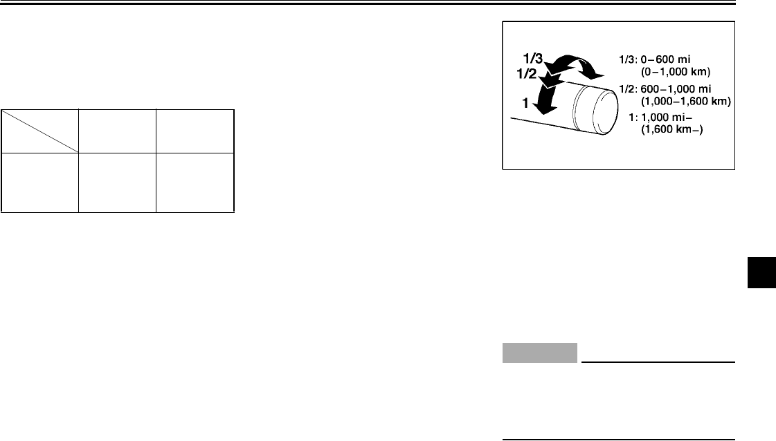
OPERATION AND IMPORTANT RIDING POINTS
6-6
6
EAU02974
Recommended shift points
The recommended shift points during
acceleration and deceleration are
shown in the table below.
CF-04E
EAU01128
Engine break-in
There is never a more important period
in the life of your engine than the period
between 0 and 1,000 mi (1,600 km).
For this reason, you should read the
following material carefully.
Since the engine is brand new, do not
put an excessive load on it for the first
1,000 mi (1,600 km). The various parts
in the engine wear and polish them-
selves to the correct operating clear-
ances. During this period, prolonged
full-throttle operation or any condition
that might result in engine overheating
must be avoided.
EAU01171*
0–600 mi (0–1,000 km)
Avoid prolonged operation above
1/3 throttle.
600–1,000 mi (1,000–1,600 km)
Avoid prolonged operation above
1/2 throttle.
EC000056*
CAUTION:
@
After 600 mi (1,000 km) of operation,
the engine oil and final gear oil must
be changed, and the oil filter car-
tridge replaced.
@
Acceleration
shift point
mi/h (km/h)
Deceleration
shift point
mi/h (km/h)
1st →2nd
2nd →3rd
3rd →4th
4th →5th
13 (20)
19 (30)
25 (40)
31 (50)
16 (25)
16 (25)
16 (25)
16 (25)

OPERATION AND IMPORTANT RIDING POINTS
6-7
6
1,000 mi (1,600 km) and beyond
The vehicle can now be operated nor-
mally.
EC000049
CAUTION:
@
If any engine trouble should occur
during the engine break-in period,
immediately have a Yamaha dealer
check the vehicle.
@
EAU00457
Parking
When parking, stop the engine, re-
move the key from the main switch,
and then turn the fuel cock lever to
“OFF”.
EW000058
WARNING
@
●Since the engine and exhaust
system can become very hot,
park in a place where pedestri-
ans or children are not likely to
touch them.
●Do not park on a slope or on
soft ground, otherwise the
motorcycle may overturn.
@

7
PERIODIC MAINTENANCE AND MINOR REPAIR
Periodic maintenance ..........................................7-1
Owner’s tool kit ....................................................7-2
Periodic maintenance chart for the emission
control system ...................................................7-3
General maintenance and lubrication chart .........7-4
Removing and installing cowlings and panels .....7-7
Checking the spark plugs ..................................7-11
Canister (for California only) ..............................7-13
Engine oil and oil filter cartridge ........................7-13
Final gear oil ......................................................7-16
Coolant ..............................................................7-16
Cleaning the air filter elements ...........................7-18
Adjusting the carburetors ...................................7-20
Adjusting the throttle cable free play ..................7-21
Adjusting the valve clearance ............................7-21
Tires ...................................................................7-21
Cast wheels .......................................................7-24
Accessories and replacement parts ..................7-25
Clutch lever free play .........................................7-26
Adjusting the brake lever free play .....................7-26
Adjusting the brake pedal position .....................7-27
Adjusting the rear brake light switch ..................7-27
Checking the front and rear brake pads ............ 7-28
Checking the brake and clutch fluid levels ........ 7-29
Changing the brake and clutch fluids ................ 7-30
Checking and lubricating the cables ................. 7-30
Checking and lubricating the throttle grip and
cable ............................................................... 7-30
Checking and lubricating the brake and
shift pedals ...................................................... 7-31
Checking and lubricating the brake and
clutch levers .................................................... 7-31
Checking and lubricating the sidestand ............ 7-32
Checking the front fork ...................................... 7-32
Checking the steering ....................................... 7-33
Checking the wheel bearings ............................ 7-34
Battery ............................................................... 7-34
Replacing the fuses .......................................... 7-35
Replacing the headlight bulb ............................. 7-37
Replacing a turn signal light bulb or
the tail/brake light bulb .................................... 7-38
Supporting the motorcycle ................................ 7-39
Troubleshooting ................................................. 7-39
Troubleshooting charts ...................................... 7-40
7-1
7
EAU00462
7-
PERIODIC MAINTENANCE AND MINOR REPAIR
EAU01790
Safety is an obligation of the owner.
Periodic inspection, adjustment and lu-
brication will keep your vehicle in the
safest and most efficient condition pos-
sible. The most important points of
motorcycle inspection, adjustment, and
lubrication are explained on the follow-
ing pages.
Maintenance, replacement, or repair
of the emission control devices and
systems may be performed by any
repair establishment or individual
that is certified (if applicable).
EW000060
WARNING
@
If you are not familiar with motor-
cycle maintenance work, have a
Yamaha dealer do it for you.
@
EAU00467
PERIODIC MAINTENANCE
PROPER PERIODIC MAINTENANCE
OF YOUR MOTORCYCLE IS IMPOR-
TANT IN ORDER TO ENJOY LONG,
PLEASURABLE SERVICE. ESPE-
CIALLY IMPORTANT ARE THE
MAINTENANCE SERVICES RELAT-
ED TO EMISSIONS CONTROL.
THESE CONTROLS NOT ONLY
FUNCTION TO ENSURE CLEANER
AIR, BUT ARE ALSO VITAL TO
PROPER ENGINE OPERATION AND
MAXIMUM PERFORMANCE. IN THE
FOLLOWING PERIODIC MAINTE-
NANCE CHARTS, THE SERVICES
RELATED TO EMISSIONS CON-
TROL ARE GROUPED SEPARATE-
LY. THESE SERVICES REQUIRE
SPECIALIZED DATA, KNOWLEDGE,
AND EQUIPMENT. YAMAHA DEAL-
ERS ARE TRAINED AND EQUIPPED
TO PERFORM THESE PARTICULAR
SERVICES.
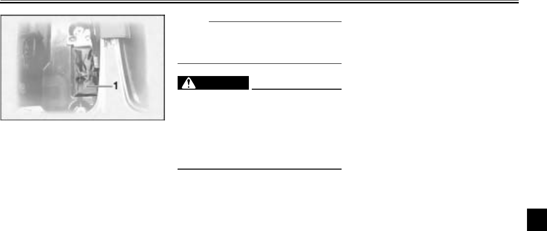
PERIODIC MAINTENANCE AND MINOR REPAIR
7-2
7
EAU03568
Owner’s tool kit
The owner’s tool kit is located inside
the right side case. (See page 3-15 for
side case opening procedures.)
The service information included in this
manual and the tools provided in the
owner’s tool kit are intended to assist
you in the performance of preventive
maintenance and minor repairs. How-
ever, additional tools such as a torque
wrench may be necessary to perform
certain maintenance work correctly.
NOTE:
@
If you do not have the tools or experi-
ence required for a particular job, have
a Yamaha dealer perform it for you.
@
EW000063
WARNING
@
Modifications not approved by
Yamaha may cause loss of perfor-
mance and render the vehicle un-
safe for use. Consult a Yamaha
dealer before attempting any chang-
es.
@
1. Owner’s tool kit
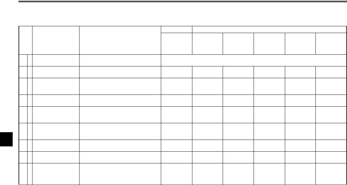
PERIODIC MAINTENANCE AND MINOR REPAIR
7-3
7
EAU00471
Periodic maintenance chart for the emission control system
*Since these items require special tools, data and technical skills, have a Yamaha dealer perform the service.
No. ITEM ROUTINE
INITIAL ODOMETER READINGS
600 mi
(1,000 km)
or
1 month
4,000 mi
(7,000 km)
or
6 months
8,000 mi
(13,000 km)
or
12 months
12,000 mi
(19,000 km)
or
18 months
16,000 mi
(25,000 km)
or
24 months
20,000 mi
(31,000 km)
or
30 months
1*Valve clearance •Check and adjust valve clearance when
engine is cold. Every 28,000 mi (43,000 km)
2Spark plug •Check condition.
•Adjust gap and clean. √Replace. √Replace. √
3*Crankcase
ventilation system
•Check ventilation hose for cracks or
damage.
•Replace if necessary. √√√√√
4*Fuel line •Check fuel hose for cracks or damage.
•Replace if necessary. √√√√√
5*Fuel filter •Replace initial 20,000 mi (31,000 km) or
30 months and thereafter every 20,000 mi
(31,000 km) or 30 months. Replace.
6*Exhaust system •Check for leakage.
•Retighten if necessary.
•Replace gasket(s) if necessary. √√√√√
7*Carburetor
synchronization •Adjust synchronization of carburetors. √√√√√√
8*Idle speed •Check and adjust engine idle speed.
•Adjust cable free play. √√√√√√
9*
Evaporative
Emission control
system (For
California only)
•Check control system for damage.
•Replace if necessary. √√
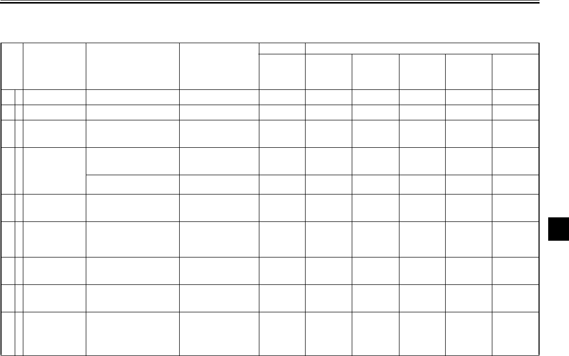
PERIODIC MAINTENANCE AND MINOR REPAIR
7-4
7
EAU00472
General maintenance and lubrication chart
No. ITEM ROUTINE TYPE
INITIAL ODOMETER READINGS
600 mi
(1,000 km)
or
1 month
4,000 mi
(7,000 km)
or
6 months
8,000 mi
(13,000 km)
or
12 months
12,000 mi
(19,000 km)
or
18 months
16,000 mi
(25,000 km)
or
24 months
20,000 mi
(31,000 km)
or
30 months
1Engine oil •Replace. See page 9-1. √√√
2*Oil filter •Replace. -√√√
3*Air filter
(See NOTE page
7-6.)
•Clean with compressed
air.
•Replace if necessary. -√√√√√
4*Cooling system
•Check hoses for cracks or
damage, replace if
necessary. -√√√√√
•Replace coolant every
24 months. Ethylene glycol
antifreeze coolant Replace.
5*Brake system
(See NOTE page
7-6.)
•Adjust free play.
•Check and replace pads if
necessary. -√√√√
Replace
brake fluid. √
6*Clutch
•Check operation and fluid
leakage. (See NOTE page
7-6.)
•Correct if necessary.
-√√√√√√
7*Final gear oil •Check vehicle for leakage.
•Replace every 16,000 mi
(25,000 km) or 24 months.
SAE 80 API “GL-4”
hypoid gear oil Replace. Check. Replace.
8*Control cable •Apply chain lube
thoroughly.
Yamaha chain and
cable lube or SAE
10W30 motor oil √√√√√√
9*Rear arm pivot
bearing
•Check bearing assembly
for looseness.
•Moderately repack every
16,000 mi (25,000 km) or
24 months.
Medium weight wheel
bearing grease √Repack.
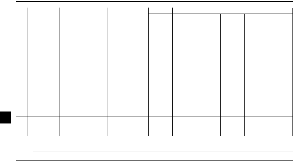
PERIODIC MAINTENANCE AND MINOR REPAIR
7-5
7
*Since these items require special tools, data and technical skills, have a Yamaha dealer perform the service.
EAU03907
NOTE:
_
From 24,000 mi (37,000 km) or 36 months, repeat the maintenance intervals starting from 4,000 mi (7,000 km) or 6 months.
_
10 Brake/
Clutch lever
pivot shaft •Apply chain lube lightly. Lithium-soap-based
grease
(all-purpose grease) √√√√√
11 Brake pedal
and shift
pedal shaft
•Lubricate
•Apply chain lube lightly.
Lithium-soap-based
grease
(all-purpose grease) √√√√√
12 *Sidestand pivot •Check operation and
lubricate.
•Apply chain lube lightly.
Lithium-soap-based
grease
(all-purpose grease) √√√√√
13 *Sidestand switch •Check and clean or
replace if necessary. -√√√√√√
14 *Front fork •Check operation and for
leakage. -√√√√√
15 *Steering
bearings
•Check bearing assembly
for looseness.
•Moderately repack every
16,000 mi (25,000 km) or
24 months.
Medium weight wheel
bearing grease. √√√
Repack. √
16 *Wheel bearings •Check bearings for
smooth rotation. -√√√√√
17 *Rear suspen-
sion link pivots •Apply grease lightly. Molybdenum disulfide
grease √
No. ITEM ROUTINE TYPE
INITIAL ODOMETER READINGS
600 mi
(1,000 km)
or
1 month
4,000 mi
(7,000 km)
or
6 months
8,000 mi
(13,000 km)
or
12 months
12,000 mi
(19,000 km)
or
18 months
16,000 mi
(25,000 km)
or
24 months
20,000 mi
(31,000 km)
or
30 months
PERIODIC MAINTENANCE AND MINOR REPAIR
7-6
7
EAU03892
NOTE:
_
●The air filter needs more frequent service if you are riding in unusually wet or dusty areas.
●Hydraulic brake and clutch systems
•After disassembling the brake or clutch master cylinders, caliper cylinders or clutch release cylinder, always change
the fluid. Regularly check the brake and clutch fluid levels and fill the reservoirs as required.
•Replace the oil seals on the inner parts of the brake or clutch master cylinders, caliper cylinders and clutch release
cylinder every two years.
•Replace the brake and clutch hoses every four years or if cracked or damaged.
_
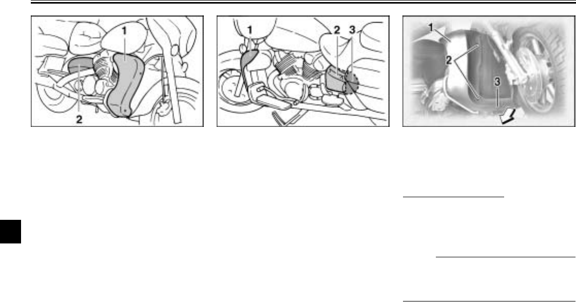
PERIODIC MAINTENANCE AND MINOR REPAIR
7-7
7
EAU01139
Removing and installing
cowlings and panels
The cowlings and panels shown above
need to be removed to perform some
of the maintenance jobs described in
this chapter. Refer to this section each
time a cowling or panel needs to be re-
moved and installed.
EAU04039
Cowling A
To remove the cowling
Remove the screws and the quick fas-
tener, and then pull the cowling off as
shown.
NOTE:
_
The quick fastener is removed by push-
ing the center pin in with a screwdriver,
then pulling the fastener out.
_
1. Cowling A
2. Panel A
1. Cowling B
2. Panel B
3. Panel C
1. Cowling A
2. Screw (× 2)
3. Quick fastener
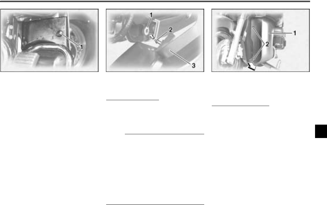
PERIODIC MAINTENANCE AND MINOR REPAIR
7-8
7
To install the cowling
Place the cowling in the original posi-
tion, and then install the screws and the
quick fastener.
NOTE:
_
●Make sure that the projection fits
into the grommet.
●To install the quick fastener, push
the center pin out so that it will pro-
trude from the fastener head, in-
sert the fastener into the cowling,
and then push the protruding pin in
until it is flush with the fastener
head.
_
EAU03634
Cowling B
To remove the cowling
1. Remove cowling A.
2. Remove the screws, and then pull
the cowling off as shown.
1. Screw 1. Grommet
2. Projection
3. Cowling A
1. Cowling B
2. Screw (× 2)
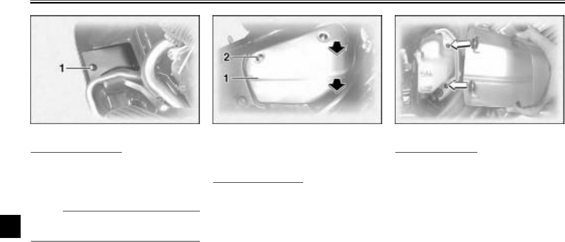
PERIODIC MAINTENANCE AND MINOR REPAIR
7-9
7
To install the cowling
1. Place the cowling in the original
position, and then install the
screws.
NOTE:
@
Make sure that the projection fits into
the grommet.
@
2. Install cowling A.
EAU00488
Panel A
To remove the panel
Remove the screw, and then pull the
panel off as shown.
To install the panel
Place the panel in the original position,
and then install the screw.
1. Screw 1. Panel A
2. Screw
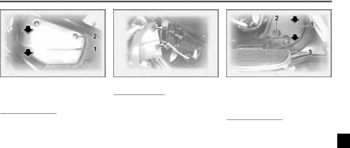
PERIODIC MAINTENANCE AND MINOR REPAIR
7-10
7
EAU00488
Panel B
To remove the panel
Remove the screw, and then pull the
panel off as shown.
To install the panel
Place the panel in the original position,
and then install the screw. EAU01795
Panel C
To remove the panel
1. Remove the left passenger foot-
rest by removing the bolts.
2. Remove the screw, and then pull
the panel off as shown.
1. Panel B
2. Screw
1. Panel C
2. Screw
3. Bolt (× 2)
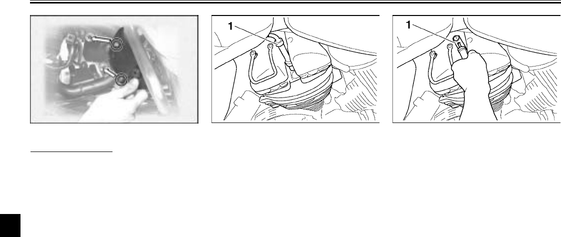
PERIODIC MAINTENANCE AND MINOR REPAIR
7-11
7
To install the panel
1. Place the panel in the original po-
sition, and then install the screw.
2. Install the passenger footrest by
installing the bolts.
EAU03329
Checking the spark plugs
The spark plugs are important engine
components, which are easy to check.
Since heat and deposits will cause any
spark plug to slowly erode, the spark
plugs should be removed and checked
in accordance with the periodic mainte-
nance and lubrication chart. In addition,
the condition of the spark plugs can re-
veal the condition of the engine.
To remove a spark plug
1. Remove the spark plug cap.
2. Remove the spark plug as shown,
with the spark plug wrench includ-
ed in the owner’s tool kit.
To check the spark plugs
1. Check that the porcelain insulator
around the center electrode on
each spark plug is a medium-to-
light tan (the ideal color when the
motorcycle is ridden normally).
2. Check that all spark plugs installed
in the engine have the same color.
1. Spark plug cap 1. Spark plug wrench
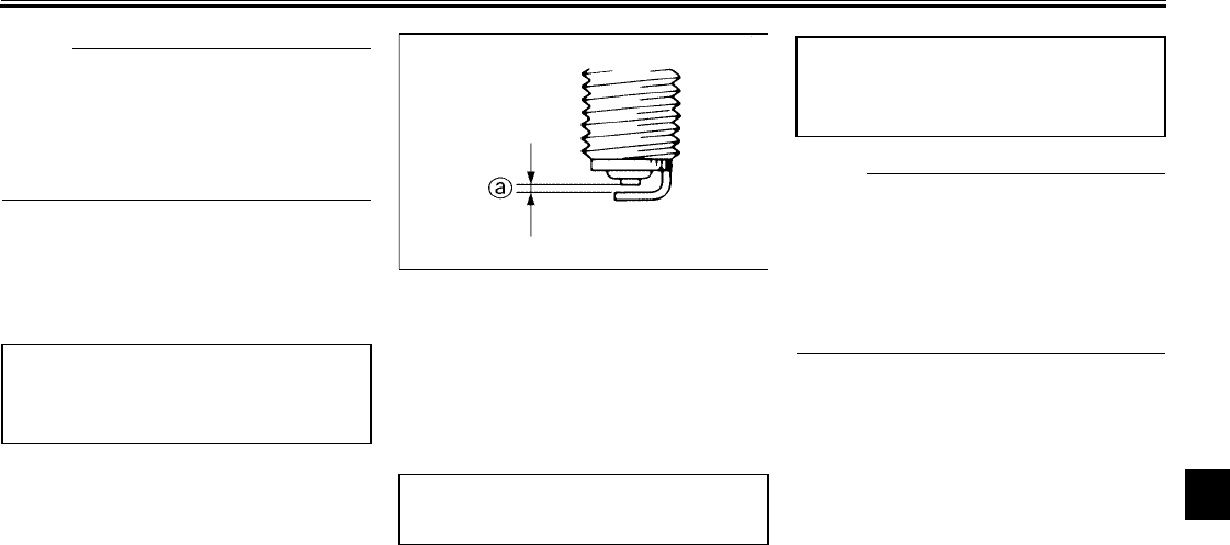
PERIODIC MAINTENANCE AND MINOR REPAIR
7-12
7
NOTE:
_
If any spark plug shows a distinctly dif-
ferent color, the engine could be defec-
tive. Do not attempt to diagnose such
problems yourself. Instead, have a
Yamaha dealer check the motorcycle.
_
3. Check each spark plug for elec-
trode erosion and excessive car-
bon or other deposits, and replace
it if necessary. To install a spark plug
1. Measure the spark plug gap with a
wire thickness gauge and, if nec-
essary, adjust the gap to specifica-
tion.
2. Clean the surface of the spark
plug gasket and its mating sur-
face, and then wipe off any grime
from the spark plug threads.
3. Install the spark plug with the
spark plug wrench, and then tight-
en it to the specified torque.
NOTE:
_
If a torque wrench is not available when
installing a spark plug, a good estimate
of the correct torque is 1/4–1/2 turn
past finger tight. However, the spark
plug should be tightened to the speci-
fied torque as soon as possible.
_
4. Install the spark plug cap.
Specified spark plug:
DPR8EA-9 (NGK) or
X24EPR-U9 (DENSO)
a. Spark plug gap
Spark plug gap:
0.03–0.04 mm (0.8–0.9 in)
Tightening torque:
Spark plug:
12.5 ft·lb (12.5 m·kgf, 17.5 Nm)
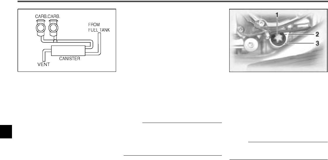
PERIODIC MAINTENANCE AND MINOR REPAIR
7-13
7
EAU01796
Canister (for California only)
This model is equipped with a canister
to prevent the discharging of fuel vapor
into the atmosphere.
●Check each hose connection.
●Check each hose and canister for
cracks or damage. Replace if
damaged.
●Make sure the vent hose is not
blocked. Clean it if necessary.
EAU04082
Engine oil and oil filter
cartridge
The engine oil level should be checked
before each ride. In addition, the oil
must be changed and the oil filter car-
tridge replaced at the intervals speci-
fied in the periodic maintenance and
lubrication chart.
To check the engine oil level
1. Place the motorcycle on a level
surface and hold it in an upright
position.
NOTE:
_
Make sure that the motorcycle is posi-
tioned straight up when checking the oil
level. A slight tilt to the side can result in
a false reading.
_
2. Start the engine, warm it up for
several minutes, and then turn it
off.
3. Wait a few minutes until the oil set-
tles, and then check the oil level
through the check window located
at the bottom-right side of the
crankcase.
NOTE:
_
The engine oil should be between the
minimum and maximum level marks.
_
4. If the engine oil is below the mini-
mum level mark, add sufficient oil
of the recommended type to raise
it to the correct level.
1. Engine oil level window
2. Maximum level mark
3. Minimum level mark
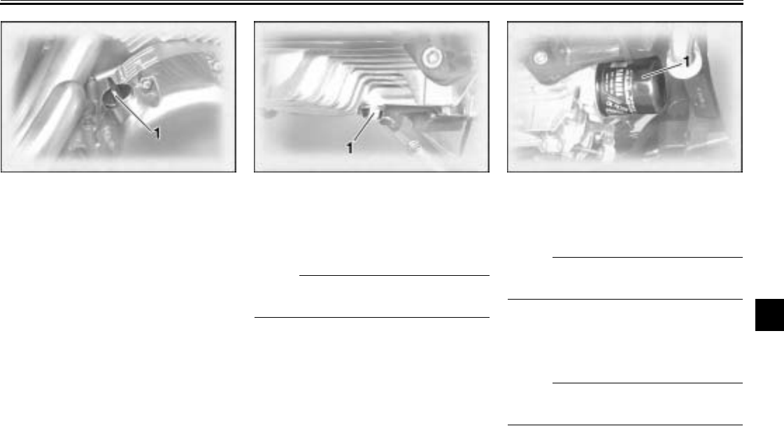
PERIODIC MAINTENANCE AND MINOR REPAIR
7-14
7
To change the engine oil
(with or without oil filter cartridge
replacement)
1. Start the engine, warm it up for
several minutes, and then turn it
off.
2. Place an oil pan under the engine
to collect the used oil.
3. Remove the engine oil filler cap
and drain bolt to drain the oil from
the crankcase.
NOTE:
_
Skip steps 4–6 if the oil filter cartridge is
not being replaced.
_
4. Remove the oil filter cartridge with
an oil filter wrench.
NOTE:
_
An oil filter wrench is available at a
Yamaha dealer.
_
5. Apply a thin coat of engine oil to
the O-ring of the new oil filter car-
tridge.
NOTE:
_
Make sure that the O-ring is properly
seated.
_
1. Engine oil filler cap 1. Engine oil drain bolt 1. Engine oil filter cartridge
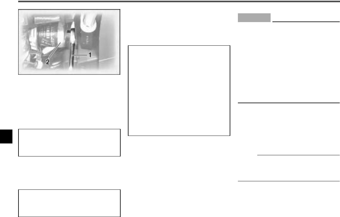
PERIODIC MAINTENANCE AND MINOR REPAIR
7-15
7
6. Install the new oil filter cartridge
with an oil filter wrench, and then
tighten it to the specified torque
with a torque wrench.
7. Install the engine oil drain bolt, and
then tighten it to the specified
torque.
8. Add the specified amount of the
recommended engine oil, and
then install and tighten the oil filler
cap.
EC000072
CAUTION:
_
●In order to prevent clutch slip-
page (since the engine oil also
lubricates the clutch), do not
mix any chemical additives with
the oil or use oils of a higher
grade than “CD”. In addition, do
not use oils labeled “ENERGY
CONSERVING II” or higher.
●Make sure that no foreign mate-
rial enters the crankcase.
_
9. Start the engine, and then let it idle
for several minutes while checking
it for oil leakage. If oil is leaking,
immediately turn the engine off
and check for the cause.
NOTE:
_
After the engine is started, the engine
oil level warning light should go off if the
oil level is sufficient.
_
1. Torque wrench
2. Oil filter wrench
Tightening torque:
Oil filter cartridge:
12 ft·lb (1.7 m·kgf, 17 Nm)
Tightening torque:
Engine oil drain bolt:
31 ft·lb (4.3 m·kgf, 43 Nm)
Recommended engine oil:
See page 9-1.
Oil quantity:
Without oil filter cartridge
replacement:
3.7 US qt (3.1 Imp qt, 3.5 L)
With oil filter cartridge
replacement:
3.9 US qt (3.3 Imp qt, 3.7 L)
Total amount (dry engine):
4.6 US qt (3.8 Imp qt, 4.3 L)
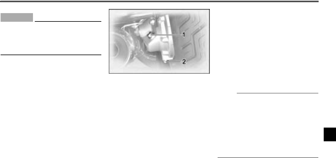
PERIODIC MAINTENANCE AND MINOR REPAIR
7-16
7
EC000067
CAUTION:
_
If the oil level warning light flickers
or remains on, immediately turn the
engine off and have a Yamaha deal-
er check the vehicle.
_
10. Turn the engine off, and then
check the oil level and correct it if
necessary.
EAU01220
Final gear oil
The final gear case must be checked
for oil leakage before each ride. If any
leakage is found, have a Yamaha deal-
er check and repair the motorcycle. In
addition, have a Yamaha dealer
change the final gear oil at the intervals
specified in the periodic maintenance
and lubrication chart.
EAU01797
Coolant
To check the coolant level
1. Place the motorcycle on a level
surface and hold it in an upright
position.
2. Remove panel A. (See page 7-9
for panel removal and installation
procedures.)
N
O
TE:
@
●The coolant level must be checked
on a cold engine since the level
varies with engine temperature.
●Make sure that the motorcycle is
positioned straight up when
checking the coolant level. A slight
tilt to the side can result in a false
reading.
@
1. Final gear oil filler bolt
2. Final gear oil drain bolt
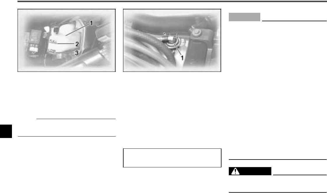
PERIODIC MAINTENANCE AND MINOR REPAIR
7-17
7
3. Check the coolant level in the
coolant reservoir.
NOTE:
@
The coolant should be between the
minimum and maximum level marks.
@
4. If the coolant is at or below the
minimum level mark, remove the
rider seat (See page 3-13 for rider
seat removal and installation pro-
cedures.), open the reservoir cap,
add coolant to the maximum level
mark, and then close the reservoir
cap and install the rider seat.
EC000080
CAUTION:
@
●If coolant is not available, use
distilled water or soft tap water
instead. Do not use hard water
or salt water since it is harmful
to the engine.
●If water has been used instead
of coolant, replace it with cool-
ant as soon as possible, other-
wise the engine may not be
sufficiently cooled and the cool-
ing system will not be protected
against frost and corrosion.
●If water has been added to the
coolant, have a Yamaha dealer
check the antifreeze content of
the coolant as soon as possible,
otherwise the effectiveness of
the coolant will be reduced.
@
EW000067
WARNING
@
Never attempt to remove the radia-
tor cap when the engine is hot.
@
5. Install the panel.
1. Coolant reservoir
2. Maximum level mark
3. Minimum level mark
1. Coolant reservoir cap
Coolant reservoir capacity:
0.89 US qt (0.74 Imp qt, 0.84 L)
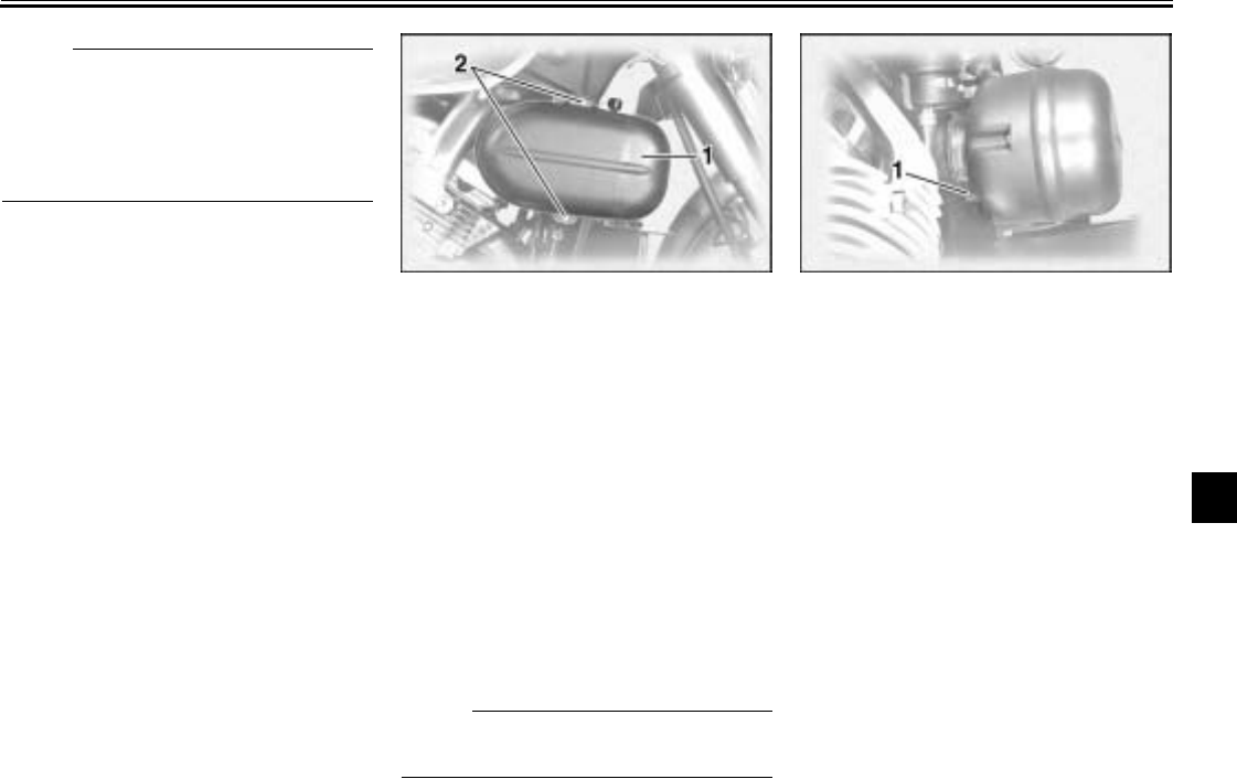
PERIODIC MAINTENANCE AND MINOR REPAIR
7-18
7
NOTE:
@
The radiator fan is automatically
switched on or off according to the
coolant temperature in the radiator. If
the engine overheats, see page 7-41
for further instructions.
@
EAU03569*
Cleaning the air filter
elements
The air filter elements should be
cleaned at the intervals specified in the
periodic maintenance and lubrication
chart. Clean the air filter elements more
frequently if you are riding in unusually
wet or dusty areas.
1. Remove cowlings A and B. (See
pages 7-7 and 7-8 for cowling re-
moval and installation procedures.)
NOTE:
@
Continue as follows for each air filter
element.
@
2. Remove the air filter case by re-
moving the bolts.
3. Loosen the air filter joint clamp
screw, and then pull the air filter
off.
1. Air filter case
2. Bolt (× 2)
1. Air filter joint clamp screw
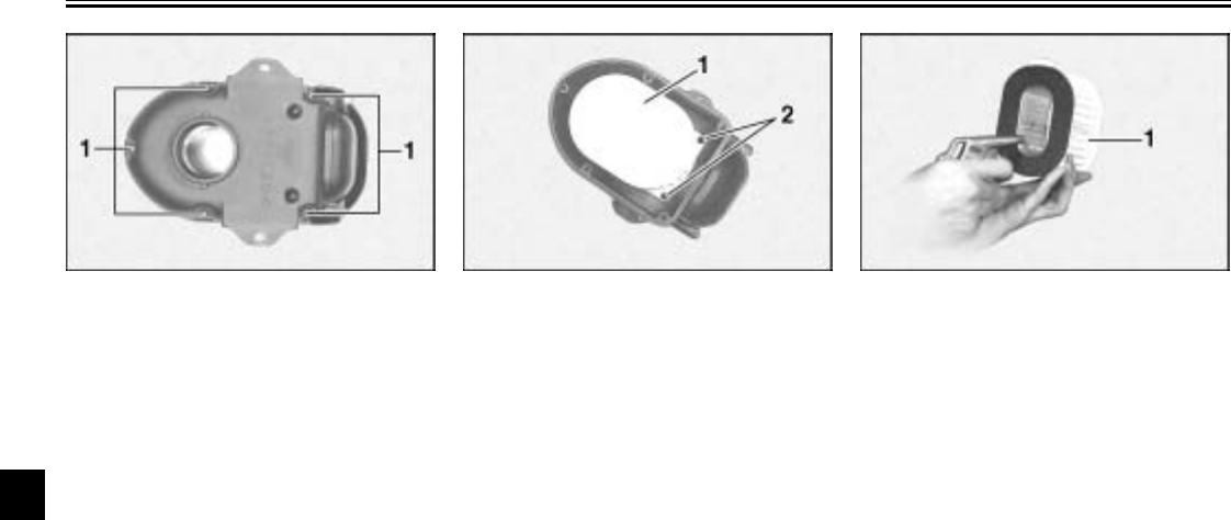
PERIODIC MAINTENANCE AND MINOR REPAIR
7-19
7
4. Remove the air filter case cover by
removing the bolts. 5. Remove the air filter element by
removing the screws.
6. Lightly tap the air filter element to
remove most of the dust and dirt,
and then blow the remaining dirt
out with compressed air as shown.
If the air filter element is damaged,
replace it.
1. Air filter case bolt (× 5) 1. Air filter element
2. Air filter element screw (× 2)
1. Air filter element
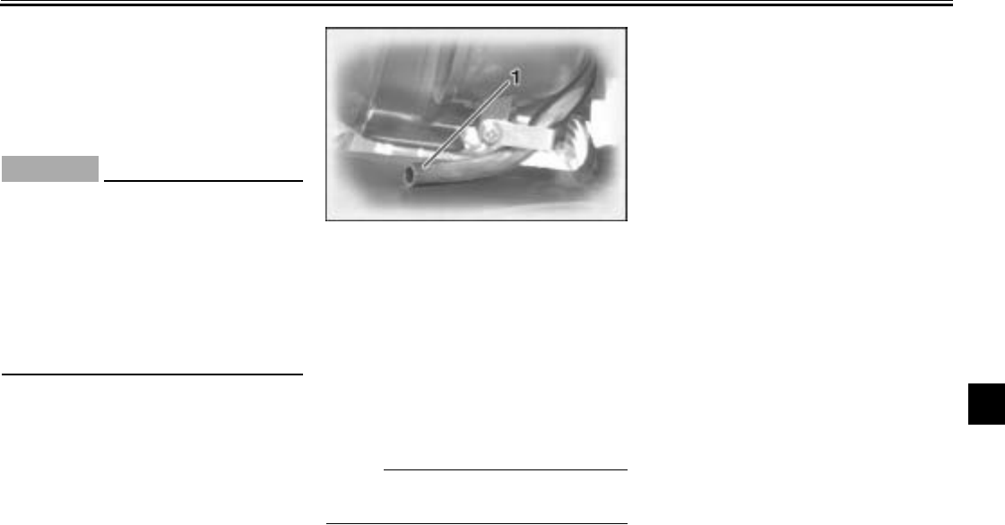
PERIODIC MAINTENANCE AND MINOR REPAIR
7-20
7
7. Install the air filter element by fit-
ting the projection on the air filter
element into the holder in the air
filter case, then tightening the
screws.
EC000082*
CAUTION:
@
●Make sure that the air filter ele-
ment is properly seated in the
air filter case.
●The engine should never be op-
erated without the air filter ele-
ment installed, otherwise the
pistons and/or cylinders may
become excessively worn.
@
8. Install the air filter case cover by
installing the bolts.
9. Install the air filter by pushing it
onto the air filter joint, then tighten-
ing the air filter joint clamp screw.
10. Install the air filter case by install-
ing the bolts.
11. Install the cowlings.
NOTE:
@
Make sure that the air filter case drain
hose is routed as shown.
@
EAU00628
Adjusting the carburetors
The carburetors are important parts of
the engine and emission control sys-
tem, which require very sophisticated
adjustment. Therefore, all carburetor
adjustments should be left to a
Yamaha dealer, who has the neces-
sary professional knowledge and expe-
rience.
1. Air filter case drain hose
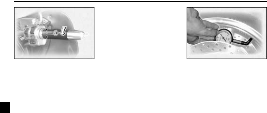
PERIODIC MAINTENANCE AND MINOR REPAIR
7-21
7
EAU00635
Adjusting the throttle cable
free play
The throttle cable free play should
measure 0.16–0.24 in (4–6 mm) at the
throttle grip. Periodically check the
throttle cable free play and, if neces-
sary, have a Yamaha dealer adjust it.
EAU00637
Adjusting the valve clearance
The valve clearance changes with use,
resulting in improper air-fuel mixture
and/or engine noise. To prevent this
from occurring, the valve clearance
must be adjusted by a Yamaha dealer
at the intervals specified in the periodic
maintenance and lubrication chart.
EAU03570
Tires
To maximize the performance, durabil-
ity, and safe operation of your motor-
cycle, note the following points
regarding the specified tires.
Tire air pressure
The tire air pressure should be
checked and, if necessary, adjusted
before each ride.
a. Throttle cable free play
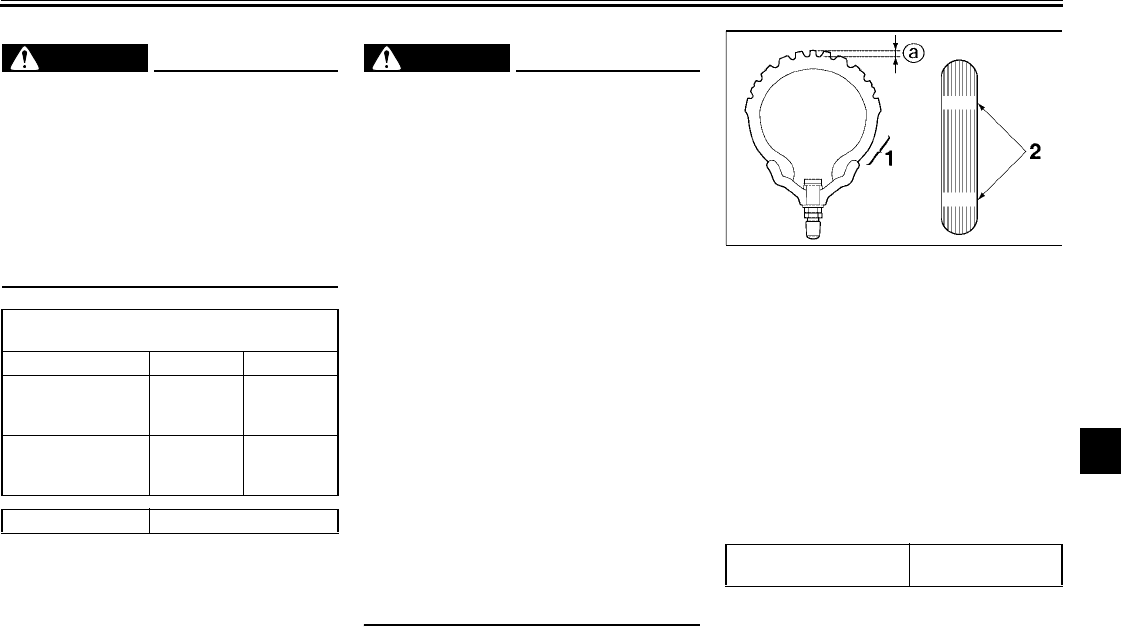
PERIODIC MAINTENANCE AND MINOR REPAIR
7-22
7
EWA00041
WARNING
@
Tire inflation pressure should be
checked and adjusted when the
temperature of the tire equals the
ambient air temperature. Tire infla-
tion pressure must be adjusted ac-
cording to total weight of cargo,
rider, passenger, and accessories
(cowling, side cases, etc.).
@
CE-05E
CE-16E
EWA00042
WARNING
@
Proper loading of your motorcycle
is important for several characteris-
tics of your motorcycle, such as
handling, braking, performance and
safety. Do not carry loosely packed
items that can shift. Securely pack
your heaviest items close to the
center of the motorcycle, and dis-
tribute the weight evenly from side
to side. Properly adjust the suspen-
sion for your load, and check the
condition and pressure of your tires.
NEVER OVERLOAD YOUR MOTOR-
CYCLE. Make sure the total weight
of the cargo, rider, passenger, and
accessories (cowling, side cases,
etc. if approved for this model) does
not exceed the maximum load of the
motorcycle. Operation of an over-
loaded motorcycle could cause tire
damage, an accident, or even injury.
@
Tire inspection
Always check the tires before operating
the motorcycle. If a tire tread shows
crosswise lines (minimum tread depth),
if the tire has a nail or glass fragments
in it, or if the side wall is cracked, con-
tact a Yamaha dealer immediately and
have the tire replaced.
CE-23E
Tire air pressure
(measured on cold tires)
Load* Front Rear
Up to 198 lb (90 kg)
250 kPa
2.50 kgf/cm2
36 psi
250 kPa
2.50 kgf/cm2
36 psi
198 lb (90 kg)–
maximum
250 kPa
2.50 kgf/cm2
36 psi
280 kPa
2.80 kgf/cm2
41 psi
Maximum load* 419 lb (190 kg)
*Total weight of rider, passenger, cargo and
accessories
1. Sidewall
2. Wear indicator
a. Tire tread depth
Minimum tire tread depth
(front and rear) 0.04 in (1.0 mm)
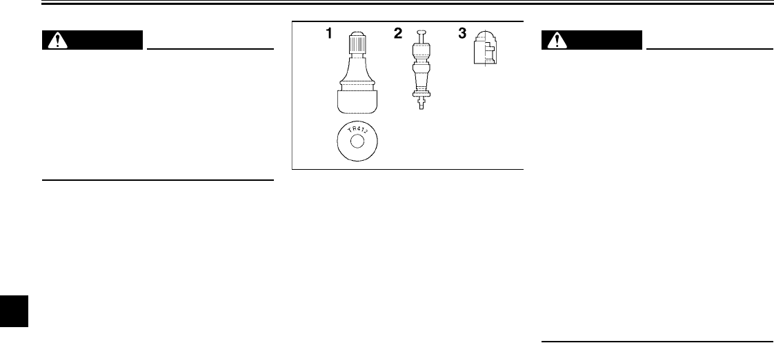
PERIODIC MAINTENANCE AND MINOR REPAIR
7-23
7
EW000085
WARNING
@
It is dangerous to ride with a worn-
out tire. When a tire tread begins to
show lines, have a Yamaha dealer
replace the tire immediately. Brakes,
tires and related wheel parts re-
placement should also be left to a
Yamaha dealer.
@
Tire information
This motorcycle is equipped with tube-
less tires, tire air valves and cast
wheels.
EW000132
WARNING
@
●The front and rear tires should
be of the same make and de-
sign, otherwise the handling
characteristics of the motor-
cycle cannot be guaranteed.
●After extensive tests, only the
tires listed below have been ap-
proved for this model by
Yamaha Motor Co., Ltd.
●Always make sure that the valve
caps are securely installed to
prevent air pressure leakage.
●Use only the tire valves and
valve cores listed below to
avoid tire deflation during a
ride.
@
1. Tire air valve
2. Valve core
3. Valve cap with seal
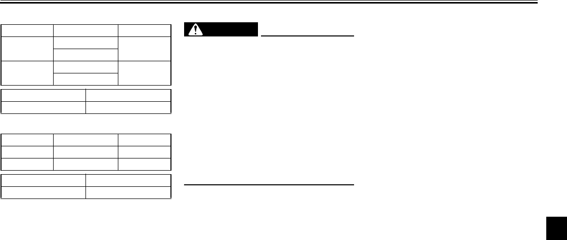
PERIODIC MAINTENANCE AND MINOR REPAIR
7-24
7
CE-11E
CE-12E
EAU00682
WARNING
_
●It is dangerous to ride with a
worn-out tire. When a tire tread
begins to show crosswise lines,
have a Yamaha dealer replace
the tire immediately.
●The replacement of all wheel-
and brake-related parts, includ-
ing the tires, should be left to a
Yamaha dealer, who has the
necessary professional knowl-
edge and experience.
_
EAU03763
Cast wheels
To maximize the performance, durabil-
ity, and safe operation of your motor-
cycle, note the following points
regarding the specified wheels.
●The wheel rims should be checked
for cracks, bends, warpage or
damage before each ride. If any
damage is found, have a Yamaha
dealer replace the wheel. Do not
attempt even the smallest repair to
the wheel. A deformed or cracked
wheel must be replaced.
●The wheel should be balanced
whenever either the tire or wheel
has been changed or replaced. An
unbalanced wheel can result in
poor performance, adverse han-
dling characteristics, and a short-
ened tire life.
●Ride at moderate speeds after
changing a tire since the tire sur-
face must first be “broken in” for it
to develop its optimal characteris-
tics.
FRONT
Manufacturer Size Type
Dunlop 150/80-16 71H D404F
150/80-16 M/C 71H
Bridgestone 150/80-16 71H G705
150/80-16 M/C 71H
Tire air valve TR412
Valve core #9000A
REAR
Manufacturer Size Type
Dunlop 150/90B 15M/C 74H D404
Bridgestone 150/90B 15M/C 74H G702
Tire air valve PVR59A
Valve core #9000
PERIODIC MAINTENANCE AND MINOR REPAIR
7-25
7
●After repairing or replacing the
rear tire, tighten the valve stem nut
and locknut to the specified
torques.
EAU00691
Accessories and replacement
parts
EW000098
WARNING
@
This motorcycle is not designed to
pull a trailer or to be attached to a
sidecar. The accessories or replace-
ment parts you choose for your
motorcycle should be designed spe-
cifically for this model, and they
must be securely mounted to main-
tain the inherent stability of the orig-
inal design. Genuine Yamaha Parts
and Accessories are designed and
tested to be compatible with your
motorcycle. Please consider Genu-
ine Yamaha Parts and Accessories
before making a purchase. Use of
non-Yamaha-approved accessories
or replacement parts may cause
loss of handling stability and riding
safety. Since Yamaha cannot con-
trol the quality of accessories or
parts manufactured by other com-
panies, Yamaha cannot be held lia-
ble for any consequences caused
by the use of items which have not
been approved by Yamaha.
@
Tightening torques:
Valve stem nut:
1.16 ft·lb (0.16 m·kgf, 1.6 Nm)
Valve stem locknut:
1.16 ft·lb (0.16 m·kgf, 1.6 Nm)
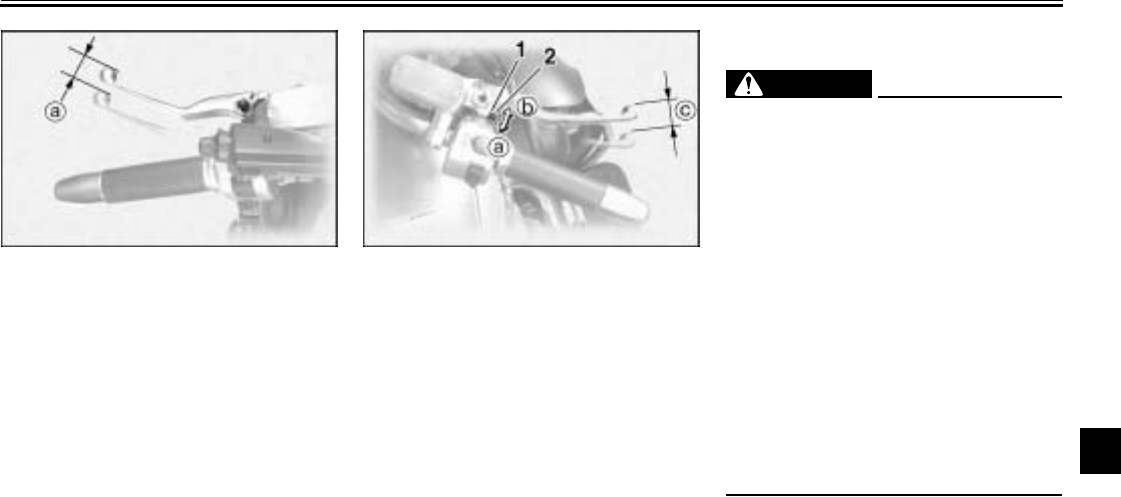
PERIODIC MAINTENANCE AND MINOR REPAIR
7-26
7
EAU00695
Clutch lever free play
Since this model is equipped with a hy-
draulic clutch, adjusting the clutch lever
free play is not needed. However, it is
necessary to check the clutch fluid lev-
el and check the hydraulic system for
leakage before each ride. If the clutch
lever free play does become exces-
sive, and shifting becomes rough or
clutch slippage occurs, causing poor
acceleration, there may be air in the
clutch system. If there is air in the hy-
draulic system, have a Yamaha dealer
bleed the system before operating the
motorcycle.
EAU00696
Adjusting the brake lever free
play
The brake lever free play should mea-
sure 0.08–0.2 in (2–5 mm) as shown.
Periodically check the brake lever free
play and, if necessary, adjust it as fol-
lows.
1. Loosen the locknut at the brake le-
ver.
2. To increase the brake lever free
play, turn the adjusting bolt in di-
rection a. To decrease the brake
lever free play, turn the adjusting
bolt in direction b.
3. Tighten the locknut.
EW000099
WARNING
@
●After adjusting the brake lever
free play, check the free play
and make sure that the brake is
working properly.
●A soft or spongy feeling in the
brake lever can indicate the
presence of air in the hydraulic
system. If there is air in the hy-
draulic system, have a Yamaha
dealer bleed the system before
operating the motorcycle. Air in
the hydraulic system will dimin-
ish the braking performance,
which may result in loss of con-
trol and an accident.
@
a. Clutch lever free play 1. Locknut
2. Adjusting bolt
c. Brake lever free play
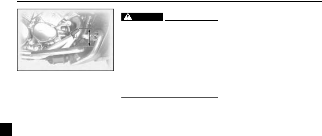
PERIODIC MAINTENANCE AND MINOR REPAIR
7-27
7
EAU01746
Adjusting the brake pedal
position
The top of the brake pedal should be
positioned approximately 3.9 in
(100 mm) above the top of the footrest
as shown. Periodically check the brake
pedal position and, if necessary, have
a Yamaha dealer adjust it.
EW000109
WARNING
@
A soft or spongy feeling in the brake
pedal can indicate the presence of
air in the hydraulic system. If there
is air in the hydraulic system, have a
Yamaha dealer bleed the system be-
fore operating the motorcycle. Air in
the hydraulic system will diminish
the braking performance, which
may result in loss of control and an
accident.
@
EAU01799
Adjusting the rear brake light
switch
The rear brake light switch, which is ac-
tivated by the brake pedal, is properly
adjusted when the brake light comes
on just before braking takes effect.
Since the brake light switch is a compo-
nent of the cruise control system, it
must be adjusted by a Yamaha dealer,
who has the necessary professional
knowledge and experience.
a. Distance between brake pedal and footrest
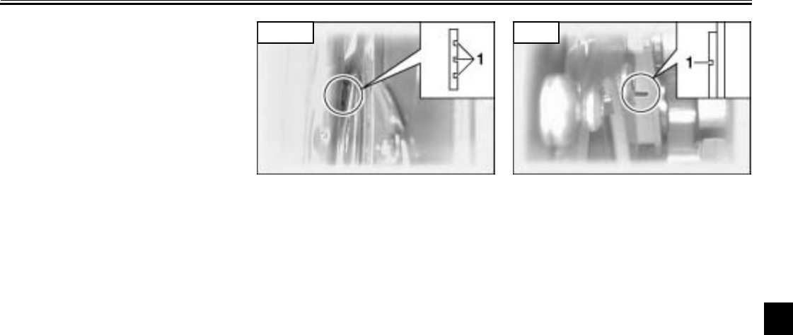
PERIODIC MAINTENANCE AND MINOR REPAIR
7-28
7
EAU00721
Checking the front and rear
brake pads
The front and rear brake pads must be
checked for wear at the intervals spec-
ified in the periodic maintenance and
lubrication chart.
EAU03938
Front brake pads
Each front brake pad is provided with
wear indicator grooves, which allow
you to check the brake pad wear with-
out having to disassemble the brake.
To check the brake pad wear, check
the wear indicator grooves. If a brake
pad has worn to the point that the wear
indicator grooves have almost disap-
peared, have a Yamaha dealer replace
the brake pads as a set.
EAU03939
Rear brake pads
Each rear brake pad is provided with a
wear indicator groove, which allows
you to check the brake pad wear with-
out having to disassemble the brake.
To check the brake pad wear, check
the wear indicator groove. If a brake
pad has worn to the point that the wear
indicator groove has almost disap-
peared, have a Yamaha dealer replace
the brake pads as a set.
1. Wear indicator groove (× 3)
Front
1. Wear indicator groove
Rear
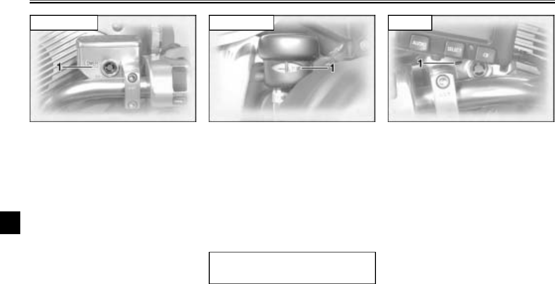
PERIODIC MAINTENANCE AND MINOR REPAIR
7-29
7
EAU03914
Checking the brake and clutch
fluid levels
Insufficient brake or clutch fluid may al-
low air to enter the brake or clutch sys-
tems, possibly causing them to
become ineffective.
Before riding, check that the brake and
clutch fluids are above the minimum
level marks and replenish if necessary.
A low brake or clutch fluid level may in-
dicate brake or clutch system leakage
and/or worn brake pads. If the brake or
clutch levels are low, be sure to check
the brake or clutch systems for leakage
and the brake pads for wear.
Observe these precautions:
●When checking the brake and
clutch fluid levels, make sure that
the top of each reservoir is level.
●Use only the recommended quali-
ty brake fluid, otherwise the rubber
seals may deteriorate, causing
leakage and poor braking or clutch
performance.
●Refill with the same type of brake
fluid. Mixing fluids may result in a
harmful chemical reaction and
lead to poor braking or clutch per-
formance.
●Be careful that water does not en-
ter the brake or clutch fluid reser-
voir when refilling. Water will
significantly lower the boiling point
of the fluid and may result in vapor
lock.
●Brake fluid may deteriorate paint-
ed surfaces or plastic parts. Al-
ways clean up spilled fluid
immediately.
●As the brake pads wear, it is nor-
mal for the brake fluid level to
gradually go down. However, if the
brake fluid level goes down sud-
denly, have a Yamaha dealer
check the cause.
1. Minimum level mark
Front brake
1. Minimum level mark
Recommended brake and
clutch fluid: DOT 4 brake fluid
Rear brake
1. Minimum level mark
Clutch
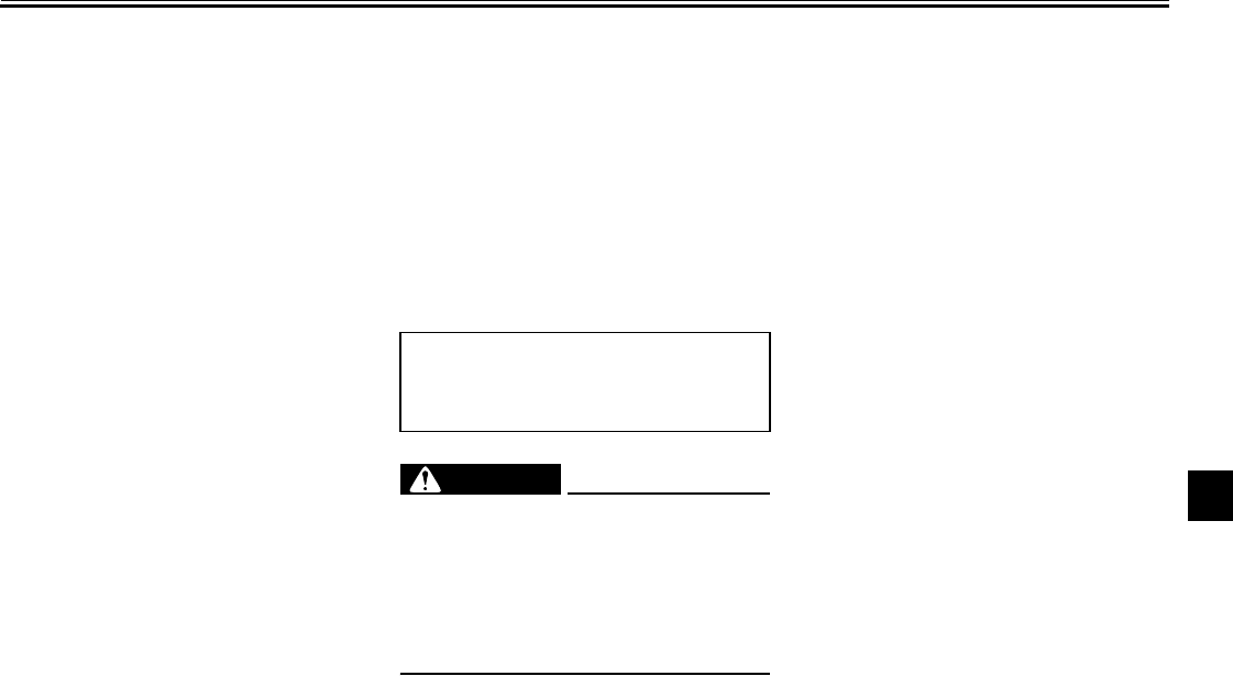
PERIODIC MAINTENANCE AND MINOR REPAIR
7-30
7
EAU03984
Changing the brake and
clutch fluids
Have a Yamaha dealer change the
brake and clutch fluids at the intervals
specified in the NOTE after the periodic
maintenance and lubrication chart. In
addition, have the oil seals of the brake
and clutch master cylinders and cali-
pers as well as the brake and clutch
hoses replaced at the intervals listed
below or whenever they are damaged
or leaking.
●Oil seals: Replace every two
years.
●Brake and clutch hoses: Replace
every four years.
EAU03297
Checking and lubricating the
cables
The operation of all control cables and
the condition of the cables should be
checked before each ride, and the ca-
bles and cable ends should be lubricat-
ed if necessary. If a cable is damaged
or does not move smoothly, have a
Yamaha dealer check or replace it.
EW000111
WARNING
_
Damage to the outer housing of ca-
bles may result in internal rusting
and cause interference with cable
movement. Replace damaged ca-
bles as soon as possible to prevent
unsafe conditions.
_
EAU04034
Checking and lubricating the
throttle grip and cable
The operation of the throttle grip should
be checked before each ride. In addi-
tion, the cable should be lubricated or
replaced at the intervals specified in
the periodic maintenance chart.
Recommended lubricant:
Yamaha Chain and Cable Lube or
engine oil SAE 10W-30 (API SE)
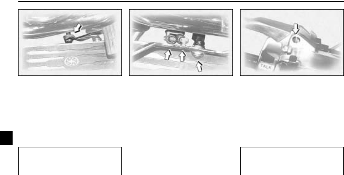
PERIODIC MAINTENANCE AND MINOR REPAIR
7-31
7
EAU03370
Checking and lubricating the
brake and shift pedals
The operation of the brake and shift
pedals should be checked before each
ride, and the pedal pivots should be lu-
bricated if necessary.
EAU03164
Checking and lubricating the
brake and clutch levers
The operation of the brake and clutch
levers should be checked before each
ride, and the lever pivots should be lu-
bricated if necessary.
Recommended lubricant:
Lithium-soap-based grease
(all-purpose grease)
Recommended lubricant:
Lithium-soap-based grease
(all-purpose grease)
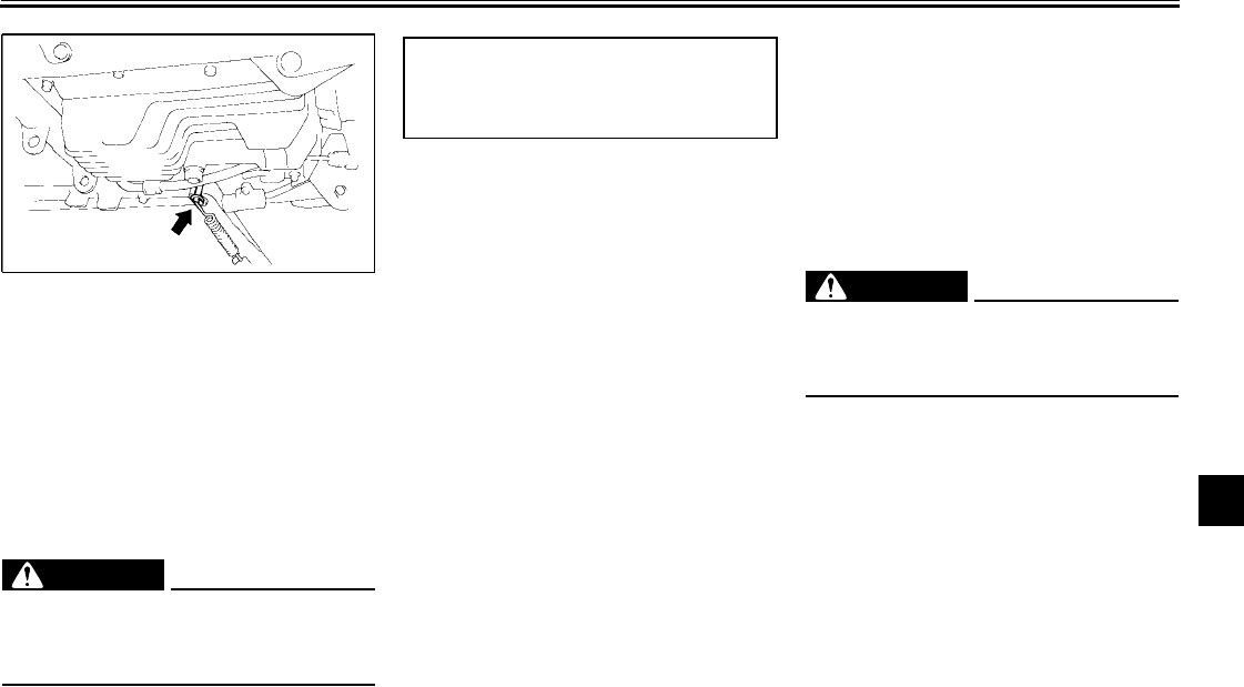
PERIODIC MAINTENANCE AND MINOR REPAIR
7-32
7
EAU03165
Checking and lubricating the
sidestand
The operation of the sidestand should
be checked before each ride, and the
sidestand pivot and metal-to-metal
contact surfaces should be lubricated if
necessary.
EW000113
WARNING
@
If the sidestand does not move up
and down smoothly, have a Yamaha
dealer check or repair it.
@
EAU02939
Checking the front fork
The condition and operation of the front
fork must be checked as follows at the
intervals specified in the periodic main-
tenance and lubrication chart.
To check the condition
EW000115
WARNING
@
Securely support the motorcycle so
that there is no danger of it falling
over.
@
Check the inner tubes for scratches,
damage and excessive oil leakage.
Recommended lubricant:
Lithium-soap-based grease
(all-purpose grease)
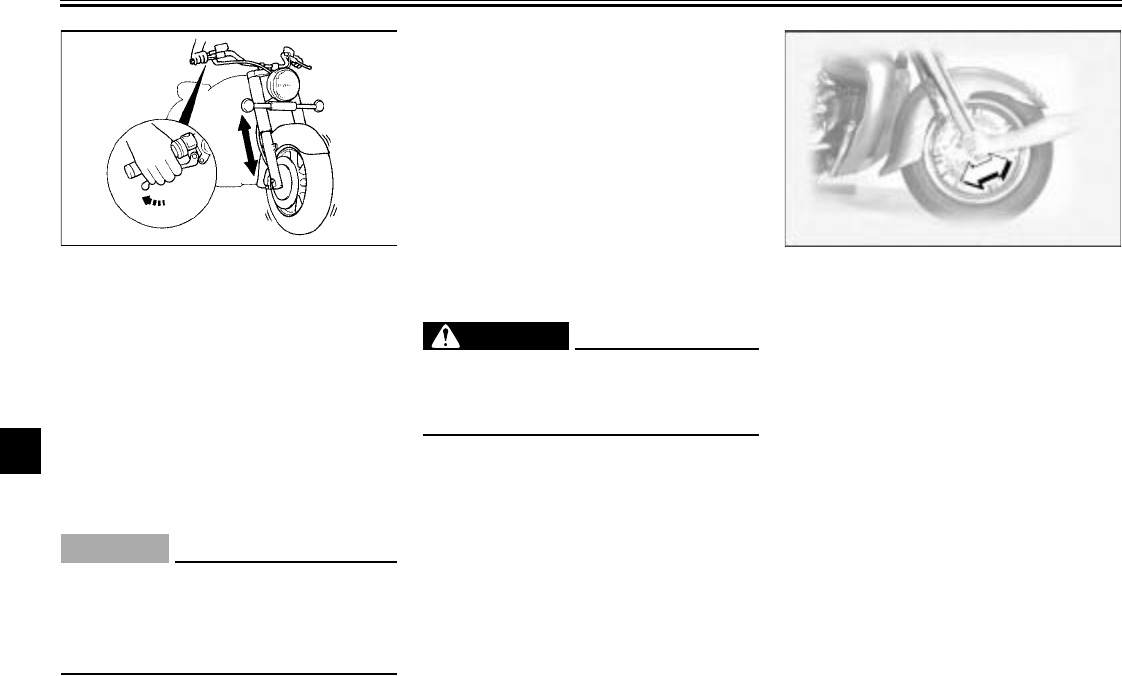
PERIODIC MAINTENANCE AND MINOR REPAIR
7-33
7
To check the operation
1. Place the motorcycle on a level
surface and hold it in an upright
position.
2. While applying the front brake,
push down hard on the handle-
bars several times to check if the
front fork compresses and re-
bounds smoothly.
EC000098
CAUTION:
@
If any damage is found or the front
fork does not operate smoothly,
have a Yamaha dealer check or re-
pair it.
@
EAU00794
Checking the steering
Worn or loose steering bearings may
cause danger. Therefore, the operation
of the steering must be checked as fol-
lows at the intervals specified in the pe-
riodic maintenance and lubrication
chart.
1. Place a stand under the engine to
raise the front wheel off the
ground.
EW000115
WARNING
@
Securely support the motorcycle so
that there is no danger of it falling
over.
@
2. Hold the lower ends of the front
fork legs and try to move them for-
ward and backward. If any free
play can be felt, have a Yamaha
dealer check or repair the steer-
ing.
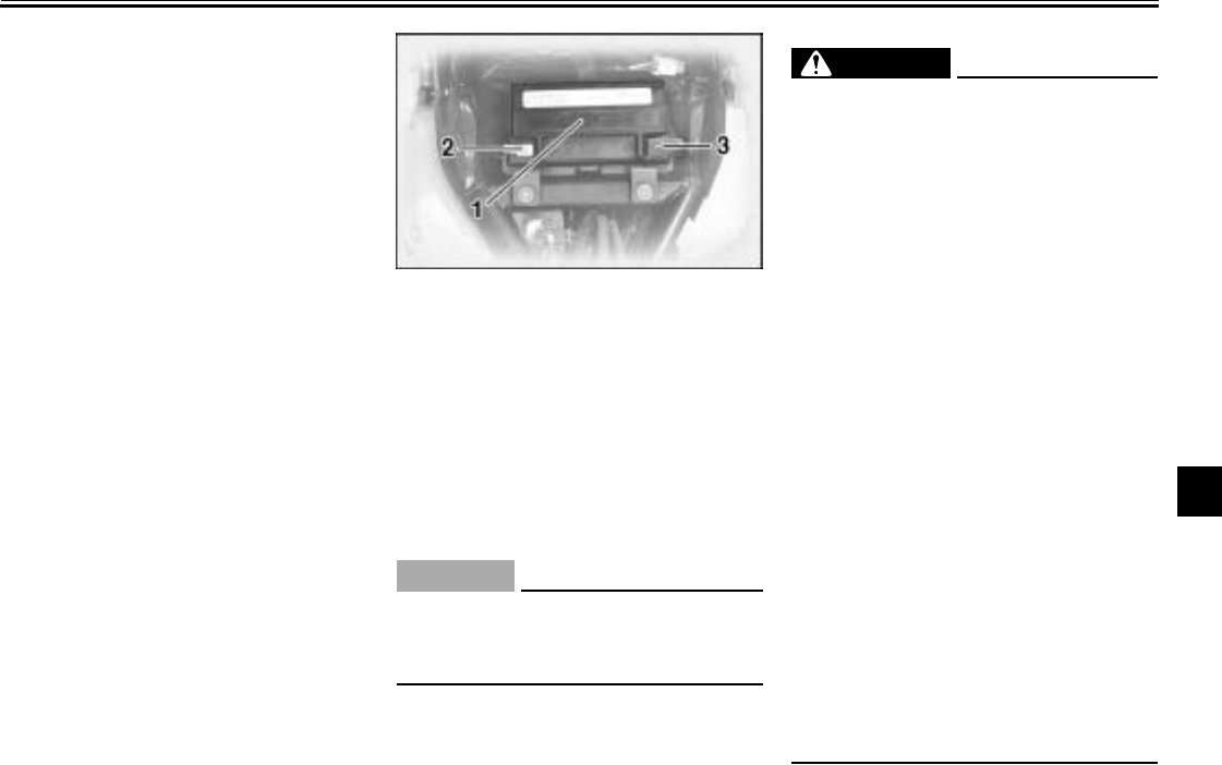
PERIODIC MAINTENANCE AND MINOR REPAIR
7-34
7
EAU01144
Checking the wheel bearings
The front and rear wheel bearings must
be checked at the intervals specified in
the periodic maintenance and lubrica-
tion chart. If there is play in the wheel
hub or if the wheel does not turn
smoothly, have a Yamaha dealer
check the wheel bearings.
EAU00800
Battery
This motorcycle is equipped with a
sealed-type (MF) battery, which does
not require any maintenance. There is
no need to check the electrolyte or to
add distilled water.
EC000101
CAUTION:
@
Never attempt to remove the battery
cell seals, as this would permanent-
ly damage the battery.
@
EW000116
WARNING
@
●Electrolyte is poisonous and
dangerous since it contains sul-
furic acid, which causes severe
burns. Avoid any contact with
skin, eyes or clothing and al-
ways shield your eyes when
working near batteries. In case
of contact, administer the fol-
lowing FIRST AID.
•EXTERNAL: Flush with plenty
of water.
•INTERNAL: Drink large quan-
tities of water or milk and im-
mediately call a physician.
•EYES: Flush with water for
15 minutes and seek prompt
medical attention.
●Batteries produce explosive hy-
drogen gas. Therefore, keep
sparks, flames, cigarettes, etc.,
away from the battery and pro-
vide sufficient ventilation when
charging it in an enclosed
space.
●KEEP THIS AND ALL BATTER-
IES OUT OF THE REACH OF
CHILDREN.
@
1. Battery
2. Negative terminal
3. Positive terminal
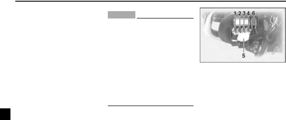
PERIODIC MAINTENANCE AND MINOR REPAIR
7-35
7
To charge the battery
Have a Yamaha dealer charge the bat-
tery as soon as possible if it seems to
have discharged. Keep in mind that the
battery tends to discharge more quickly
if the motorcycle is equipped with op-
tional electrical accessories.
To store the battery
1. If the motorcycle will not be used
for more than one month, remove
the battery, fully charge it, and
then place it in a cool, dry place.
2. If the battery will be stored for
more than two months, check it at
least once a month and fully
charge it if necessary.
3. Fully charge the battery before in-
stallation.
4. After installation, make sure that
the battery leads are properly con-
nected to the battery terminals.
EC000102
CAUTION:
@
●Always keep the battery
charged. Storing a discharged
battery can cause permanent
battery damage.
●To charge a sealed-type (MF)
battery, a special (constant-
voltage) battery charger is re-
quired. Using a conventional
battery charger will damage the
battery. If you do not have ac-
cess to a sealed-type (MF) bat-
tery charger, have a Yamaha
dealer charge your battery.
@
EAU01801
Replacing the fuses
The main fuse box is located behind
panel C. (See page 7-10 for panel re-
moval and installation procedures.)
Fuse box 1 is located behind cowling A.
(See page 7-7 for cowling removal and
installation procedures.)
1. Cruise control fuse
2. Carburetor heater fuse
3. Auxiliary DC terminal fuse
4. Auxiliary DC jack fuse
5. Audio system fuse
6. Spare fuse (× 2)
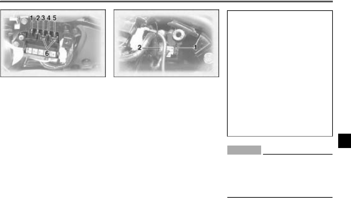
PERIODIC MAINTENANCE AND MINOR REPAIR
7-36
7
Fuse box 2 is located behind panel B.
(See page 7-8 for panel removal and
installation procedures.)
If a fuse is blown, replace it as follows.
1. Turn the key to “OFF” and turn off
the electrical circuit in question.
2. Remove the blown fuse, and then
install a new fuse of the specified
amperage. EC000103
CAUTION:
@
Do not use a fuse of a higher amper-
age rating than recommended to
avoid causing extensive damage to
the electrical system and possibly a
fire.
@
1. Odometer fuse
2. Radiator fan fuse
3. Headlight fuse
4. Signaling system fuse
5. Ignition fuse
6. Spare fuse (× 2)
1. Main fuse
2. Spare main fuse
Specified fuses:
Fuse box 1
Cruise control fuse: 10 A
Carburetor heater fuse: 10 A
Auxiliary DC terminal
fuse: 5 A
Auxiliary DC jack fuse: 5 A
Audio system fuse: 10 A
Fuse box 2
Ignition fuse: 10 A
Signaling system fuse: 15 A
Headlight fuse: 15 A
Radiator fan fuse: 10 A
Odometer fuse: 10 A
Main fuse: 30 A
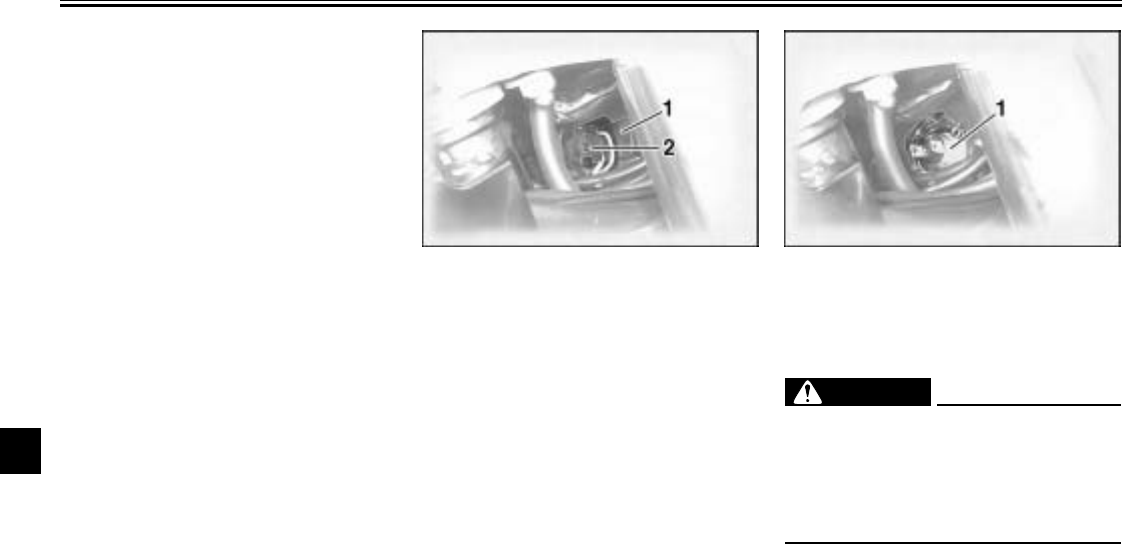
PERIODIC MAINTENANCE AND MINOR REPAIR
7-37
7
3. Turn the key to “ON” and turn on
the electrical circuit in question to
check if the device operates.
4. If the fuse immediately blows
again, have a Yamaha dealer
check the electrical system.
EAU01802
Replacing the headlight bulb
This motorcycle is equipped with a
quartz bulb headlight. If the headlight
bulb burns out, replace it as follows.
1. Disconnect the headlight coupler,
and then remove the headlight
bulb cover.
2. Remove the headlight bulb holder
by turning it counterclockwise, and
then remove the defective bulb.
EW000119
WARNING
@
Headlight bulbs get very hot. There-
fore, keep flammable products away
from a lit headlight bulb, and do not
touch the bulb until it has cooled
down.
@
3. Place a new bulb into position, and
then secure it with the bulb holder.
1. Bulb cover
2. Headlight coupler
1. Bulb holder
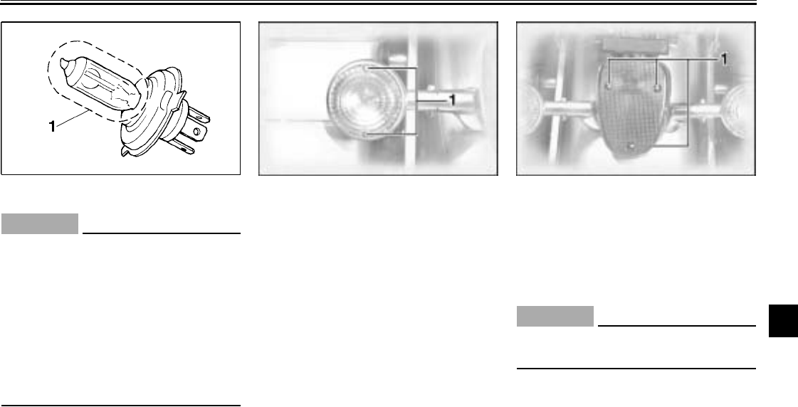
PERIODIC MAINTENANCE AND MINOR REPAIR
7-38
7
EC000105
CAUTION:
@
Do not touch the glass part of the
headlight bulb to keep it free from
oil, otherwise the transparency of
the glass, the luminosity of the bulb,
and the bulb life will be adversely af-
fected. Thoroughly clean off any dirt
and fingerprints on the headlight
bulb using a cloth moistened with
alcohol or thinner.
@
4. Install the bulb cover, and then
connect the coupler.
5. Have a Yamaha dealer adjust the
headlight beam if necessary.
EAU00855
Replacing a turn signal light
bulb or the tail/brake light
bulb
1. Remove the lens by removing the
screws.
2. Remove the defective bulb by
pushing it in and turning it counter-
clockwise.
3. Insert a new bulb into the socket,
push it in, and then turn it clock-
wise until it stops.
4. Install the lens by installing the
screws.
EC000108
CAUTION:
@
Do not overtighten the screws, oth-
erwise the lens may break.
@
1. Do not touch this area. 1. Screw (× 2) 1. Screw (× 3)

PERIODIC MAINTENANCE AND MINOR REPAIR
7-39
7
EAU01579
Supporting the motorcycle
Since this model is not equipped with a
centerstand, follow these precautions
when removing the front and rear
wheel or performing other mainte-
nance requiring the motorcycle to
stand upright. Check that the motor-
cycle is in a stable and level position
before starting any maintenance. A
strong wooden box can be placed un-
der the engine for added stability.
To service the front wheel
1. Stabilize the rear of the motorcycle
by using a motorcycle stand or, if
an additional motorcycle stand is
not available, by placing a jack un-
der the frame in front of the rear
wheel.
2. Raise the front wheel off the
ground by using a motorcycle
stand.
To service the rear wheel
Raise the rear wheel off the ground by
using a motorcycle stand or, if a motor-
cycle stand is not available, by placing
a jack either under each side of the
frame in front of the rear wheel or under
each side of the swingarm.
EAU03087
Troubleshooting
Although Yamaha motorcycles receive
a thorough inspection before shipment
from the factory, trouble may occur dur-
ing operation. Any problem in the fuel,
compression, or ignition systems, for
example, can cause poor starting and
loss of power.
The following troubleshooting charts
represent quick and easy procedures
for checking these vital systems your-
self. However, should your motorcycle
require any repair, take it to a Yamaha
dealer, whose skilled technicians have
the necessary tools, experience, and
know-how to service the motorcycle
properly.
Use only genuine Yamaha replace-
ment parts. Imitation parts may look
like Yamaha parts, but they are often
inferior, have a shorter service life and
can lead to expensive repair bills.
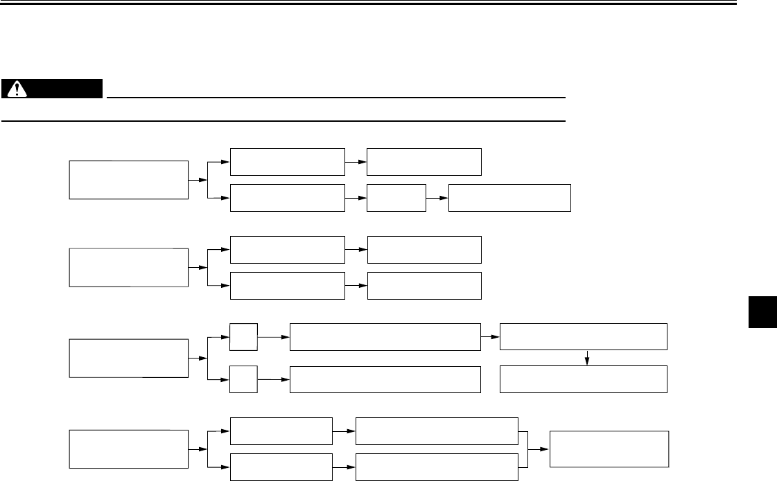
PERIODIC MAINTENANCE AND MINOR REPAIR
7-40
7
EAU02990
Troubleshooting charts
Starting problems or poor engine performance
EW000125
WARNING
@
Keep away open flames and do not smoke while checking or working on the fuel system.
@
Check the fuel level in
the fuel tank.
1. Fuel There is enough fuel.
There is no fuel.
Check the compression.
Supply fuel. The engine does not start.
Check the compression.
Operate the electric starter.
2. Compression There is compression.
There is no compression.
Check the ignition.
Have a Yamaha dealer
check the vehicle.
Remove the spark plugs
and check the electrodes.
3. Ignition Wipe off with a dry cloth and correct the
spark plug gaps, or replace the spark plugs.
Have a Yamaha dealer check the vehicle.
The engine does not start.
Have a Yamaha dealer
check the vehicle.
Operate the electric starter.
4. Battery The engine turns over
quickly.
The engine turns over
slowly.
Dry
Wet
The engine does not start.
Check the battery.
Open the throttle halfway and operate
the electric starter.
The battery is good.
Check the battery lead connections,
and charge the battery if necessary.
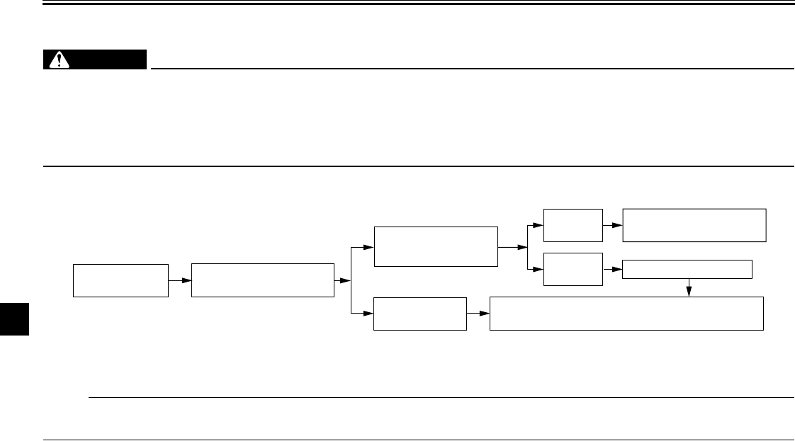
PERIODIC MAINTENANCE AND MINOR REPAIR
7-41
7
Engine overheating
EW000070
WARNING
@
●Do not remove the radiator cap when the engine and radiator are hot. Scalding hot fluid and steam may be
blown out under pressure, which could cause serious injury. Be sure to wait until the engine has cooled.
●After removing the radiator cap retaining bolt, place a thick rag, like a towel, over the radiator cap, and then
slowly rotate the cap counterclockwise to the detent to allow any residual pressure to escape. When the hiss-
ing sound has stopped, press down on the cap while turning it counterclockwise, and then remove the cap.
@
NOTE:
@
If coolant is not available, tap water can be temporarily used instead, provided that it is changed to the recommended coolant
as soon as possible.
@
Wait until the
engine has cooled. Check the coolant level in the
reservoir and radiator.
The coolant level
is OK.
The coolant level is low.
Check the cooling system
for leakage.
Have a Yamaha dealer check
and repair the cooling system.
Add coolant. (See NOTE.)
Start the engine. If the engine overheats again, have a
Yamaha dealer check
and repair the cooling system.
There is
leakage.
There is
no leakage.

CLEANING AND STORAGE
8
Cleaning ............................................................................................ 8-1
Storage .............................................................................................. 8-3
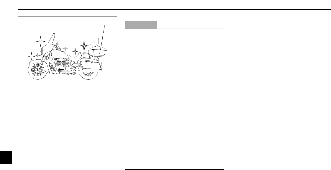
8-1
8
EAU01010
8-
CLEANING AND STORAGE
EAU03333
Cleaning
Frequent, thorough cleaning of your
motorcycle not only enhances its ap-
pearance, but also improves its perfor-
mance and extends its life.
ECA00001
CAUTION:
@
●Improper cleaning can damage
the windshield, cowlings, pan-
els and other plastic parts. Use
only a soft, clean cloth or
sponge with mild detergent and
water to clean plastic. If the
windshield is scratched, use a
quality plastic polishing com-
pound after washing.
●Do not use any harsh chemical
products on plastic parts. Make
sure to avoid using cloths or
sponges which have been in
contact with strong or abrasive
cleaning products, solvent or
thinner, fuel (gasoline), rust re-
movers or inhibitors, brake flu-
id, antifreeze or electrolyte.
@
Before cleaning the motorcycle
1. Cover the muffler outlets, to pre-
vent water entry, with plastic bags
and strong rubber bands.
2. Make sure that the spark plugs
and all caps and covers are prop-
erly installed.
3. Apply Yamaha Mud and Grease
Release or another high-quality
degreaser to the crankcase, to re-
move any excessive grease, with
a paintbrush. Do not apply de-
greaser to the wheel axles.
CLEANING AND STORAGE
8-2
8
Cleaning the motorcycle
1. Rinse any dirt and degreaser off
with a garden hose, using only
enough pressure to do the job.
ECA00032
CAUTION:
@
●Do not use high-pressure wash-
ers, since excessive high pres-
sure may cause water seepage
and deterioration of wheel bear-
ings, the front fork, brakes,
transmission seals, audio sys-
tem, speakers, saddlebags,
travel trunk and electrical parts.
●Many expensive repair bills
have resulted from improper
high-pressure washer applica-
tions, such as those available at
coin-operated car washers.
@
2. Once the majority of the dirt has
been hosed off, wash all surfaces
with warm water and a mild deter-
gent. Use a toothbrush or bottle-
brush to get into those hard-to-
reach places.
3. Rinse the motorcycle off immedi-
ately with clean water and dry all
surfaces with a chamois, clean
towel, or soft absorbent cloth.
4. Clean the seat with Yamaha Pro-
tectant or another high-quality vi-
nyl upholstery cleaner to keep the
cover pliable and glossy.
Cleaning the windshield
Avoid using any alkaline or strong acid
cleaner, gasoline, brake fluid, or any
other solvent. Clean the windshield
with a cloth or sponge dampened with
a mild detergent, and then wash it off
thoroughly with water. For additional
cleaning, use Yamaha Windshield
Cleaner or another high-quality wind-
shield cleaner. Some cleaning com-
pounds for plastics may leave
scratches on the windshield. Before us-
ing such cleaners, test an area of the
windshield which does not affect your
visibility and which cannot be easily
recognized.
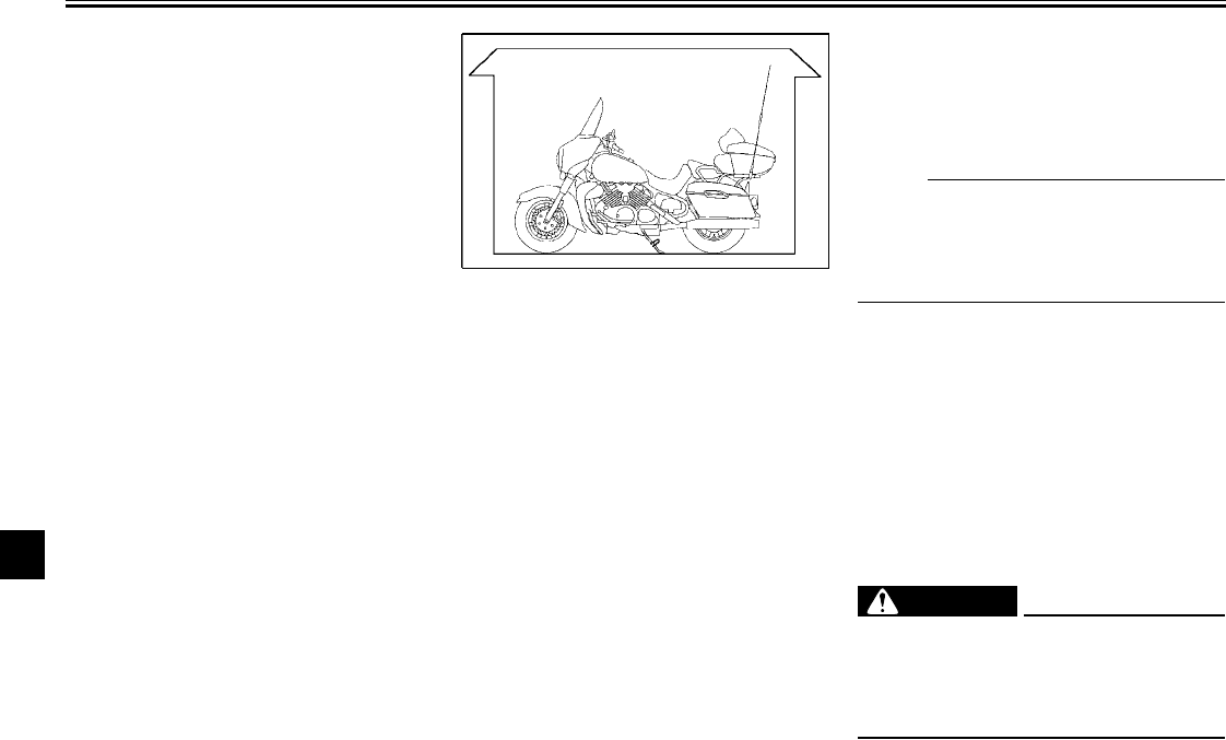
CLEANING AND STORAGE
8-3
8
After cleaning the motorcycle
Apply Yamaha Silicone Wax or another
high-quality automotive-type wax on all
painted and chrome-plated surfaces.
Avoid combination cleaner-waxes,
since many contain abrasives that may
mar the paint or protective finish. When
finished, start the engine and let it idle
for several minutes.
EAU03722
Storage
Long term storage (60 days or more) of
your motorcycle will require some pre-
ventive measures to guard against de-
terioration. After the motorcycle has
been thoroughly cleaned, prepare it for
storage as follows:
1. Fill the fuel tank with fresh fuel and
add the following amount of
Yamaha Fuel Conditioner and
Stabilizer or another high-quality
fuel stabilizer:
1 fluid oz per gallon or 7.5 ml per li-
ter
Operate the engine for several
minutes to insure the newly condi-
tioned fuel enters the entire fuel
system and carburetors.
NOTE:
_
Use of Yamaha Fuel Conditioner and
Stabilizer eliminates the need to drain
the fuel system. If necessary, have a
Yamaha dealer drain the fuel system.
_
2. Remove the spark plugs and pour
about one tablespoon of SAE
10W-30 or SAE 20W-40 engine oil
in each spark plug bore. Install the
spark plugs and ground the spark
plug leads to prevent sparking
while turning the engine over
several times to coat the cylinder
walls with oil.
EW000127
WARNING
_
To prevent sparking, make sure to
remove the spark plug leads and
ground them before using the
starter motor to crank the engine.
_
3. Lubricate all control cables.
CLEANING AND STORAGE
8-4
8
NOTE:
_
Use a Yamaha Power Cable Luber and
Yamaha Lube Zall or another high-
quality equivalent to pressure-lubricate
the cables and to purge out any mois-
ture between the inner and outer ca-
bles.
_
4. Block the frame up so that both of
its wheels are off the ground.
5. Cover the exhaust pipes with plas-
tic bags to prevent moisture from
entering them.
6. If storing in a humid or salt-air at-
mosphere, coat all exposed metal
surfaces with a light film of oil. Do
not apply oil to any rubber parts or
the seat cover.
7. Remove the battery and fully
charge it. Store it in a cool, dry
place and charge it once a month.
Do not store the battery in an ex-
cessively cold or warm place [less
than 30 °F (0 °C) or more than
90 °F (30 °C)]. For more informa-
tion on storing the battery, see
page 7-34.
NOTE:
_
If necessary, make repairs before stor-
ing the motorcycle.
_

SPECIFICATIONS
9
Specifications .................................................................................... 9-1
9-1
9
EAU01038
9-
SPECIFICATIONS
Specifications
CS-01E
Model XVZ13TF(C)
Dimensions
Overall length 104.5 in (2,655 mm)
Overall width 35.4 in (900 mm)
Overall height 61.6 in (1,565 mm)
Seat height 29.5 in (750 mm)
Wheelbase 67.1 in (1,705 mm)
Minimum ground clearance 6.1 in (155 mm)
Minimum turning radius 137.8 in (3,500 mm)
Basic weight (with oil and full
fuel tank) 869 lb (394 kg)
Engine
Engine type Liquid cooled 4-stroke, DOHC
Cylinder arrangement V-type, 4-cylinder
Displacement 1,294 cm3
Bore × stroke 3.11 × 2.60 in (79 × 66 mm)
Compression ratio 10:1
Starting system Electric starter
Lubrication system Wet sump
Engine oil
Type
Recommended engine oil
classification API Service SE, SF, SG type or
higher
Quantity
Without oil filter cartridge
replacement
3.7 US qt (3.1 lmp qt, 3.5 L)
With oil filter cartridge
replacement
3.9 US qt (3.3 lmp qt, 3.7 L)
Total amount (dry engine) 4.6 US qt (3.8 lmp qt, 4.3 L)
010 30 50 70 90 110 130 ˚
F
YAMALUBE 4 (20W-40)
or SAE 20W-40
-20 -10 010 20 30 40 50 ˚C
YAMALUBE 4 (10W-30)
or SAE 10W-30
CAUTION:
Be sure to use motor oils that do not contain anti-friction
modifiers. Passenger car motor oils (often labeled
“ENERGY CONSERVING II”) contain anti-friction additives
which will cause clutch and/or starter clutch slippage, result-
ing in reduced component life and poor engine performance.

SPECIFICATIONS
9-2
9
Final gear oil
Type SAE80API “GL-4” Hypoid Gear
Oil
Quantity 0.21 US qt (0.18 lmp qt, 0.2 L)
Cooling system capacity
(total amount) 3.7 US qt (3.1 lmp qt, 3.5 L)
Air filter Dry type element
Fuel
Type UNLEADED GASOLINE ONLY
Fuel tank capacity 5.9 US gal (5.0 lmp gal, 22.5 L)
Reserve amount 0.9 US gal (0.8 lmp gal, 3.5 L)
Carburetor
Manufacturer MIKUNI
Model × quantity BDSR32 × 4
Spark plug
Manufacturer/model NGK / DPR8EA-9 or
DENSO / X24EPR-U9
Gap 0.03–0.04 in (0.8–0.9 mm)
Clutch type Wet, multiple-disc
Transmission
Primary reduction system Spur gear
Primary reduction ratio 1.776
Secondary reduction system Shaft drive
Secondary reduction ratio 2.567
Transmission type Constant-mesh 5-speed
Operation Left foot
Gear ratio
1st 2.529
2nd 1.632
3rd 1.200
4th 0.960
5th 0.786
Chassis
Frame type Double cradle
Caster angle 29.17°
Trail 5.98 in (152 mm)
Tire
Front
Type Tubeless
Size 150/80-16 71H
150/80-16 M/C 71H
Manufacturer /
model Dunlop / D404F
Bridgestone / G705
Rear
Type Tubeless
Size 150/90B15M/C 74H
Manufacturer /
model Dunlop / D404
Bridgestone / G702

SPECIFICATIONS
9-3
9
Maximum load* 419 lb (190 kg)
Tire air pressure
(measured on cold tires)
Up to 198 lb (90 kg)
Front 36 psi (2.50 kgf/cm2, 250 kPa)
Rear 36 psi (2.50 kgf/cm2, 250 kPa)
198 lb (90 kg) -maximum*
Front 36 psi (2.50 kgf/cm2, 250 kPa)
Rear 41 psi (2.80 kgf/cm2, 280 kPa)
*Total weight of rider, passenger, cargo and accessories.
Wheels
Front
Type Cast wheel
Size 16 × MT 3.50
16 M/C × MT 3.50
Rear
Type C ast wheel
Size 15M/C × MT 4.00
Brakes
Front
Type Dual disc brake
Operation Right hand
Fluid DOT 4
Rear
Type S i ngle disc brake
Operation Right foot
Fluid DOT 4
Suspension
Front Telescopic fork
Rear Swingarm (link suspension)
Spring/shock absorber
Front Coil-air spring / oil damper
Rear Coil-air spring / oil damper
Wheel travel
Front 5.51 in (140 mm)
Rear 4.13 in (105 mm)
Electrical
Ignition system Transistorized coil ignition (digi-
tal)
Charging system
Ty p e A . C. magneto
Standard output 14 V, 29 A @ 5,000 r/min
Battery
Model YTX20L-BS
Voltage, capacity 12 V, 18 Ah
Headlight type Quartz bulb (halogen)

SPECIFICATIONS
9-4
9
Bulb voltage, wattage × quantity
Headlight 12 V, 60/55 W × 1
Tail/brake light 12 V, 8/27 W × 1
Front turn signal/position light 12 V, 27/8 W × 2
Rear turn signal light 12 V, 27 W × 2
Neutral indicator light 12 V, 1.7 W × 1
High beam indicator light 12 V, 1.7 W × 1
Oil level warning light 12 V, 1.7 W × 1
Turn signal indicator light 12 V, 1.7 W × 2
Fuel level warning light 14 V, 3 W × 1
Coolant temperature warning
light 12 V, 1.7 W × 1
Overdrive indicator light/
Engine trouble warning light 12 V, 1.7 W × 2
Cruise control “SET” indicator
light 12 V, 1.7 W × 1
Cruise control “RES” indicator
light 12 V, 1.7 W × 1
Cruise control “ON” indicator
light 12 V, 1.7 W × 1
Audio system amplifier
Output power
Speaker 14 W × 4
Headset 1 W × 2
Auto-volume range 5 steps
Output impedance
Speaker 4 Ω
Headset 8 Ω–16 Ω
Fuses
Main fuse 30 A
Headlight fuse 15 A
Signaling system fuse 15 A
Ignition fuse 10 A
Radiator fan fuse 10 A
Odometer fuse 10 A
Cruise control fuse 10 A
Carburetor heater fuse 10 A
Audio system fuse 10 A
Auxiliary DC jack fuse 5 A
Auxiliary DC terminal fuse 5 A

CONSUMER INFORMATION
10
Identification numbers ..................................................................... 10-1
Key identification number ................................................................ 10-1
Vehicle identification number ........................................................... 10-1
Model label ...................................................................................... 10-2
Reporting safety defects ................................................................. 10-3
Motorcycle noise regulation ............................................................ 10-4
Maintenance record ........................................................................ 10-5
YAM AHA MOTOR CORPORARION, U.S.A.
ROYAL STAR™ VENTURE® LIMITED WARRANTY .................... 10-7
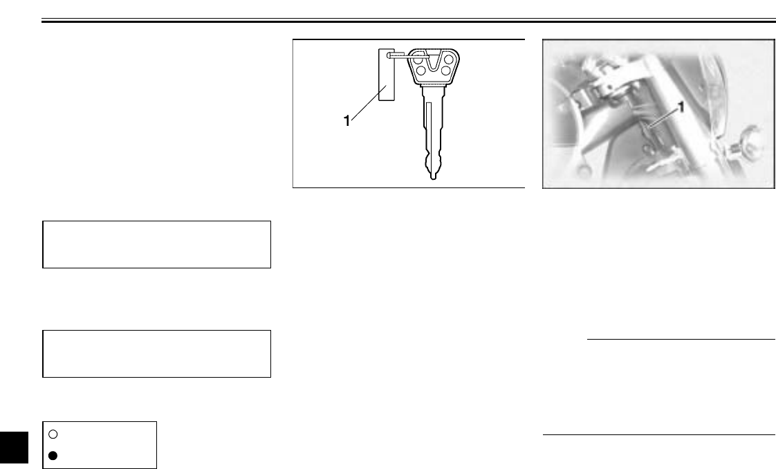
10-1
10
EAU01039
10-
CONSUMER INFORMATION
EAU02944
Identification numbers
Record the key identification number,
vehicle identification number and mod-
el label information in the spaces pro-
vided below for assistance when
ordering spare parts from a Yamaha
dealer or for reference in case the vehi-
cle is stolen.
1. KEY IDENTIFICATION NUMBER:
CA-02E
2. VEHICLE IDENTIFICATION
NUMBER:
CA-02E
3. MODEL LABEL INFORMATION:
CA-01E
EAU01041
Key identification number
The key identification number is
stamped into the key tag. Record this
number in the space provided and use
it for reference when ordering a new
key.
EAU01043
Vehicle identification number
The vehicle identification number is
stamped into the steering head pipe.
Record this number in the space pro-
vided.
NOTE:
@
The vehicle identification number is
used to identify your motorcycle and
may be used to register your motor-
cycle with the licensing authority in
your area.
@
1. Key identification number 1. Vehicle identification number
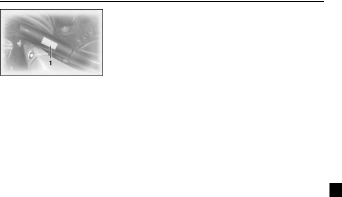
CONSUMER INFORMATION
10-2
10
EAU01804
Model label
The model label is affixed to the frame
under the rider seat. (See page 3-13 for
rider seat removal and installation pro-
cedures.) Record the information on
this label in the space provided. This in-
formation will be needed when ordering
spare parts from a Yamaha dealer.
1. Model label

CONSUMER INFORMATION
10-3
10
EAU01051
Reporting safety defects
If you believe that your vehicle has a defect which could cause a crash or could cause injury or death, you should immedi-
ately inform the National Highway Traffic Safety Administration (NHTSA) in addition to notifying Yamaha Motor Corporation,
U.S.A. If NHTSA receives similar complaints, it may open an investigation, and if it finds that a safety defect exists in a group
of vehicles, it may order a recall and remedy campaign. However, NHTSA cannot become involved in individual problems
between you, your dealer, or Yamaha Motor Corporation, U.S.A.
To contact NHTSA, you may either call the Auto Safety Hotline toll-free at 1-800-424-9393 (or 366-0123 in Washington, D.C.
area) or write to: NHTSA, U.S. Department of Transportation, Washington, D.C. 20590. You can also obtain other informa-
tion about motor vehicle safety from the Hotline.
CONSUMER INFORMATION
10-4
10
EAU01053
Motorcycle noise regulation
TAMPERING WITH NOISE CONTROL SYSTEM PROHIBITED:
Federal law prohibits the following acts or the causing thereof: (1) The removal or rendering inoperative by any person other
than for purposes of maintenance, repair, or replacement of any device or element of design incorporated into any new ve-
hicle for the purpose of noise control prior to its sale or delivery to the ultimate purchaser or while it is in use or (2) the use of
the vehicle after such device or element of design has been removed or rendered inoperative by any person.
“AMONG THOSE ACTS PRESUMED TO CONSTITUTE TAMPERING ARE THE ACTS LISTED BELOW”.
These acts include tampering with the following systems; i.e., modification, removal, etc.
CL-01E
Exhaust system
Muffler
Exhaust pipe
Silencer
Intake system
Air cleaner case
Air cleaner element
Intake duct
CONSUMER INFORMATION
10-5
10
EAU01874
Maintenance record
Copies of work orders and/or receipts for parts purchased and installed on your motorcycle will be required to document that
maintenance has been completed in accordance with the emissions warranty. The chart below is printed only as a reminder
that maintenance work is required. It is not acceptable proof of maintenance work.
CL-04E
Maintenance
interval Date of
service Mileage Servicing dealer
name and address Remarks
600 mi
(1,000 km) or
1 month
4,000 mi
( 7,000 km) or
6 months
8,000 mi
(13,000 km) or
12 months
12,000 mi
(19,000 km) or
18 months
16,000 mi
(25,000 km) or
24 months
20,000 mi
(31,000 km) or
30 months
24,000 mi
(37,000 km) or
36 months
CONSUMER INFORMATION
10-6
10
28,000 mi
(43,000 km) or
42 months
32,000 mi
(49,000 km) or
48 months
36,000 mi
(55,000 km) or
54 months
40,000 mi
(61,000 km) or
60 months
Maintenance
interval Date of
service Mileage Servicing dealer
name and address Remarks
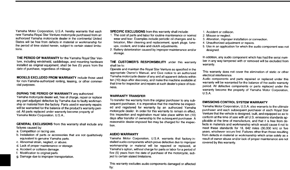
CONSUMER INFORMATION
10-7
10
EAU03066
YAMAHA MOTOR CORPORARION, U.S.A.
ROYAL STAR™ VENTURE® LIMITED WARRANTY
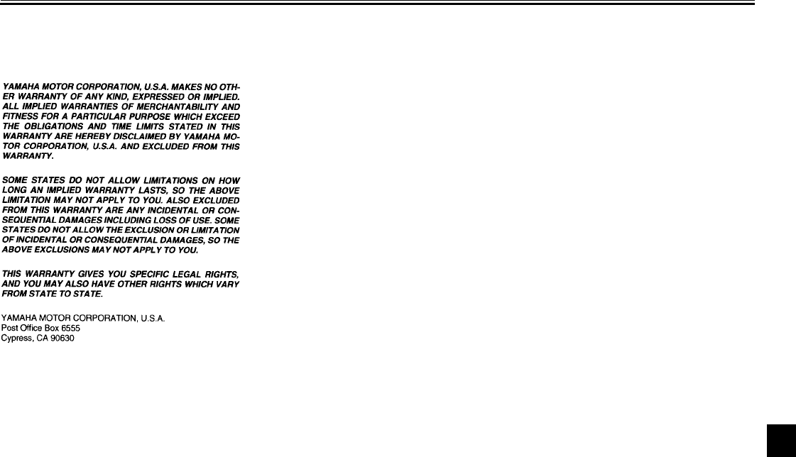
CONSUMER INFORMATION
10-8
10
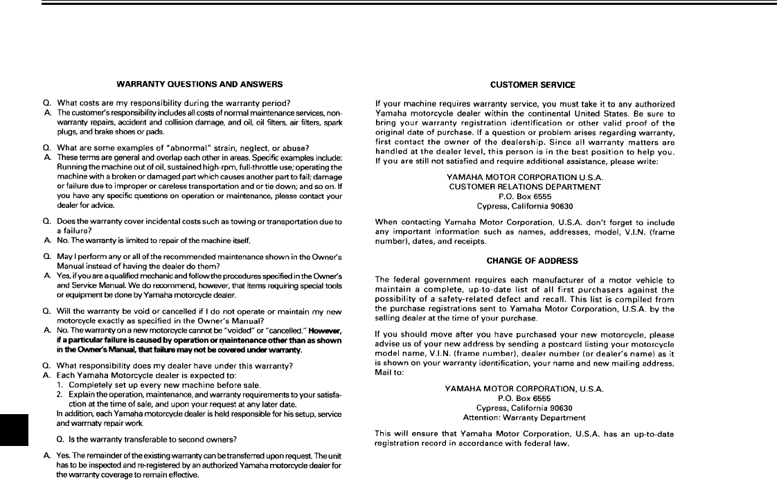
CONSUMER INFORMATION
10-9
10
11-
INDEX
A
Accessories and replacement parts .......7-25
Air filter elements, cleaning ....................7-18
Audio settings (basic)...............................4-5
Audio settings (modes) ............................4-6
Audio system ...........................................4-1
Auxiliary audio source............................4-24
Auxiliary DC jack and terminals..............3-22
B
Battery ...................................................7-34
Brake and clutch fluid levels, checking...7-29
Brake and clutch fluids, changing...........7-30
Brake and clutch levers, checking and
lubricating............................................7-31
Brake and shift pedals, checking and
lubricating............................................7-31
Brake lever...............................................3-9
Brake lever free play, adjusting ..............7-26
Brake light switch (rear), adjusting .........7-27
Brake pads, checking.............................7-28
Brake pedal............................................3-10
Brake pedal position, adjusting ..............7-27
C
Cables, checking and lubricating............7-30
Canister (for California only)...................7-13
Carburetors, adjusting............................7-20
Cassette deck operation ........................4-10
CB radio operation.................................4-18
CD changer operation............................4-17
Cleaning ..................................................8-1
Clutch lever..............................................3-9
Clutch lever free play .............................7-26
Coolant.................................................. 7-16
Checking.......................................... 7-16
Coolant temperature warning light ........... 3-4
Cowlings and panels, removing and
installing................................................ 7-7
Cruise control indicator lights................... 3-3
Cruise control switches............................ 3-8
Cruise control system.............................. 3-5
D
Dimmer switch......................................... 3-7
E
Engine break-in ....................................... 6-6
Engine oil and oil filter cartridge ............. 7-13
Engine stop switch................................... 3-8
F
Final gear oil.......................................... 7-16
Front fork, adjusting............................... 3-17
Front fork, checking ............................... 7-32
Fuel....................................................... 3-11
Fuel cock............................................... 3-12
Fuel gauge .............................................. 3-7
Fuel level warning light ............................ 3-3
Fuel tank cap......................................... 3-10
Fuses, replacing.................................... 7-35
H
Handlebar switches ................................. 3-7
Hazard switch.......................................... 3-8
Headlight bulb, replacing ....................... 7-37
Headsets................................................. 4-2
Helmet holders ...................................... 3-14
High beam indicator light ......................... 3-2
Horn switch ..............................................3-8
I
Identification numbers............................10-1
Ignition circuit cut-off system ..................3-20
Indicator and warning lights......................3-2
K
Key identification number.......................10-1
L
Labels, location........................................1-7
Locks for optional side cases and travel trunk
3-19
M
Main switch/steering lock .........................3-1
Maintenance and lubrication, periodic ......7-4
Maintenance, emission control system.....7-3
Maintenance, periodic..............................7-1
Maintenance record ...............................10-5
Model label ............................................10-2
N
Neutral indicator light ...............................3-3
Noise regulation.....................................10-4
O
Oil level warning light ...............................3-2
Overdrive indicator light/Engine trouble
warning light ..........................................3-3
P
Parking.....................................................6-7
Part locations ...........................................2-1
Parts, location of ......................................4-1
INDEX
Pre-operation check list ........................... 5-1
R
Radio operation .....................................4-13
Rider seat.............................................. 3-13
S
Safety defects, reporting........................ 10-3
Safety information....................................1-1
Shifting .................................................... 6-4
Decelerating.......................................6-5
Shift points ......................................... 6-6
Starting out and accelerating..............6-5
Shift pedal ............................................... 3-9
Shock absorber assembly, adjusting ..... 3-18
Side cases and travel trunk.................... 3-15
Sidestand ..............................................3-19
Sidestand, checking and lubricating....... 7-32
Sound control unit.................................... 4-3
Spark plugs, checking ........................... 7-11
Specifications ..........................................9-1
Speedometer unit ....................................3-4
Starter (choke) knob.............................. 3-13
Starting and warming up a cold engine....6-2
Starting a warm engine............................6-4
Start switch.............................................. 3-8
Steering, checking................................. 7-33
Steering, locking with a padlock............. 3-13
Storage....................................................8-3
Supporting the motorcycle..................... 7-39
T
Talk switch............................................... 3-7
Throttle cable free play, adjusting .......... 7-21
Throttle grip and cable, checking and
lubricating........................................... 7-30
Tires...................................................... 7-21
Tool kit .................................................... 7-2
Troubleshooting .................................... 7-39
Troubleshooting charts.......................... 7-40
Turn signal indicator lights....................... 3-2
Turn signal light or tail/brake light bulb,
replacing ............................................. 7-38
Turn signal switch ................................... 3-8
V
Valve clearance, adjusting .................... 7-21
Vehicle identification number................. 10-1
W
Warranty, limited ................................... 10-7
Wheel bearings, checking ..................... 7-34
Wheels.................................................. 7-24
PROTECT YOUR INVESTMENT
Use Genuine YAMAHA parts and Accessories.
See your Authorized YAMAHA Dealer for a Genuine YAMAHA Service Manual.
Printed on recycled paper
LIT-11626-15-33
(4XY-28199-13)
PRINTED IN JAPAN
2001 . 7 - 0.5 ×1CR
(E)
